

Page 1

Installation
Operation
Maintenance
Model: ECCO-C
Electric Full Size Convection Oven
Lang Manufacturing Company 6500 Merrill Creek Parkway Everett, WA 98203
Part Number 60800-02 Revision B Phone: 425-349-2400 Fax: 425-349-2483 July 1995
Page 2

TABLE OF CONTENTS
TABLE OF CONTENTS..............................................................................................................................1
INSTALLATION................................................................................................................... ....................... 1
RECEIVING THE OVEN....................................................................................................................... 1
DATA PLATE INFORMATION............................................................................................................ 1
CLEARANCES....................................................................................................................................... 1
LEGS....................................................................................................................................................... 1
STACKING THE OVENS...................................................................................................................... 2
ELECTRICAL CONNECTION.............................................................................................................. 2
OPERATION................................................................................................................................................ 4
GENERAL............................................................................................................................................... 4
CONTROL PANEL................................................................................................................................. 4
STATUS READOUT DISPLAY ............................................................................................................5
PRODUCT AND SHELF BUTTONS..................................................................................................... 5
PRODUCT CHANGING............................................................................................................... ....... 6
TIME RECALL..................................................................................................................................... 6
CANCEL SHELF.................................................................................................................................. 6
MANUAL PROGRAMMING................................................................................................................. 6
TEMPERATURE RECALL BUTTON................................................................................................... 7
READ/CLEAR BUTTON....................................................................................................................... 7
MANUAL CONTROL OVERRIDE....................................................................................................... 7
MAINTENANCE .......................................................................................................................................... 8
CLEANING............................................................................................................................................. 8
DOOR CHAIN ADJUSTMENT ............................................................................................................. 8
SERVICE....................................................................................................................................................... 9
CALIBRATION......................................................................................................................................9
CONTROL PANEL REMOVAL............................................................................................................ 9
ELEMENT REMOVAL.......................................................................................................................... 9
MOTOR REMOVAL.............................................................................................................................. 9
SAFETY THERMOSTAT REMOVAL................................................................................................ 10
PARTS......................................................................................................................................................... 11
CONTROL PANEL LAYOUT ............................................................................................................. 11
PARTS LIST ......................................................................................................................................... 12
WIRING DIAGRAMS ............................................................................................................................... 13
208 /240 VOLT ..................................................................................................................................... 13
480 VOLT OVEN .................................................................................................................................14
Lang Manufactur ing Company 800-224-5264
6500 Merrill Creek Parkway Fax: 425-349-2733
Everett, WA 98203
USA Copyright 1995
Page 3

INSTALLATION
RECEIVING THE OVEN
Upon receipt, check for freight damage, both
visible and concealed. Visible damage should be
noted on the freight bill at the time of delivery
and signed by the carrier's agent. Concealed loss
or damage means loss or damage which does not
become apparent until the merchandise has been
unpacked. If concealed loss or damage is
discovered upon unpacking, make a written
request for inspection by the carrier's agent
within 15 days of delivery. All packing material
should be kept for inspection. Do not return
damaged merchandise to Lang Manufacturing
Company. File your claim with the carrier.
Uncrate the appliance as near its intended
location as practical. The crating will help
protect the unit from the physical damage
normally associated with moving it through
hallways and doorways.
The installation of any components such as vent
hood, grease extractors, fire extinguisher
systems, must conform to their applicable
nationally recognized installation standards.
CLEARANCES
Standard minimum clearance from
construction is as follows:
2 inches from sides
4 inches from back
6 inches from floor
If the oven is set without legs on a
noncombustable
a 4 inch back clearance.
If the oven is set directly against a
noncombustible
clearance to the floor.
Do not
from an uncontrolled heat source, such as open
flame burners or char broilers, on the right side
(control side) unless a
installed. With the spacer installed the distance
to an uncontrolled heat source can be reduced to
3 inches.
Do not
another oven on the right hand side (control
side).
install the oven closer than 12 inches
install the oven closer than 3 inches from
floor or a curbed base maintain
back wall maintain a 6 inch
Hi Temperature Spacer
combustible
is
DATA PLATE INFORMATION
A data plate is located inside the control
compartment above the control. Look through
the perforated opening above the control panel
and to the left to view the data plate. A flashlight
my be helpful.
The oven voltage, wattage, serial number, wire
size, and clearance specifications are on the data
plate.
This information should be carefully read and
understood before proceeding with the
installation.
The oven is field settable for voltages 208 and
240. 480 volt ovens require being manufactured
for 480 volt. The phase of the oven is field
settable for single and three phase.
Refer to the ELECTRICAL section for the
instructions on setting voltage and phase.
LEGS
Legs are available for both the single and double
deck installations. Single deck installations
require a 27 inch leg. Double deck installations
require a 6 inch leg or caster.
To install the 27 inch legs, place some cardboard
on the floor and gently tip the oven onto its back.
Fasten two legs to the oven's front corners using
the four 5/16 inch bolts provided in the leg kit.
Lift the oven onto its front legs and block the
back up using one o f the 27 inch legs set upside
down in the center rear of the oven body. Install
the last 27 inch leg onto the oven body on the
control side rear. Gently lift the oven rear,
remove the leg set to support the oven center and
install it on the last rear corner.
To install the 6 inch legs or casters, attach the leg
or caster to the leg supports supplied in the oven
by following the instructions in the box, then
attach the leg support to the oven.
1
Page 4

The adjustable feet on the bottom of each leg
may be screwed in or out as necessary to level
the oven.
A spirit level placed on an oven rack will assist
in leveling the oven.
ELECTRICAL CONNECTION
The electrical connection must be made in
accordance with local codes or in the absence of
local codes with NFPA No. 70 latest edition (in
Canada use: CSA STD. C22.1)
STACKING THE OVENS
Remove all the plug buttons from the top of the
lower oven.
Remove the stacking kit from the oven
compartment of one oven and install the 1 1/4
inch plastic bushing into the top of the lower
oven.
Tip the top oven backwards and install two 3/8
inch socket head bolts, found in the stacking kit,
into the two front leg holes that match the holes
in the top of the lower oven. Install the socket
head bolts with the heads of the bolt pointing
away from the oven.
Lift the top oven and gently set on top of the
lower oven so that the heads of the socket head
bolts nest into the holes in the top of the lower
oven.
IMPORTANT
IF THE SERVICE CONNECTION IS TO BE
MADE AT THE FRONT OF THE OVEN, BE
SURE TO FEED THE TOP OVENS
SUPPLY WIRES DOWN THROUGH THE
BUSHING INSTALLED IN THE TOP OF
THE LOWER OVEN. ALL THE WIRES
SHOULD THEN TERMINATE NEAR THE
CIRCUIT BREAKERS OF THE LOWER
OVEN.
The ovens may now be set into position. Be
careful if sliding the ovens, they were not
designed to slide over cracks or obstructions in
the floor.
The electrical service entrance is provided by a 1
1/4 inch knockout in the bottom right front
corner of each oven, or at the oven back directly
behind the co ntr o l co mpa rt ment. G ro und ing lugs
are provided at both the front and rear service
entrances.
The 208/240 volt oven is a dual voltage oven and
is shipped from the factory as 208 volt. The
oven must be field converted to operate on a 240
volt power supply.
To convert the oven to 240 volt, remove the
jumper wire located on a terminal strip located
inside the lower portion to the control
compartment.
With 480 volt installations check to be sure that
the motor rotates in a clockwise direction as
viewed from the front of the oven.
To reverse the motor rotation, switch any two
incoming power supply leads and recheck the
rotation.
Supply wire size must be large enough to carry
the amperage load for the number of ovens being
installed. Wire size information can be found on
the oven DATA PLATE.
This oven can be installed on both single and
three phase supplies and is shipped from the
factory unphased .
To phase the oven to match the power supply,
follow the charts below for proper wire size and
grouping.
2
Page 5
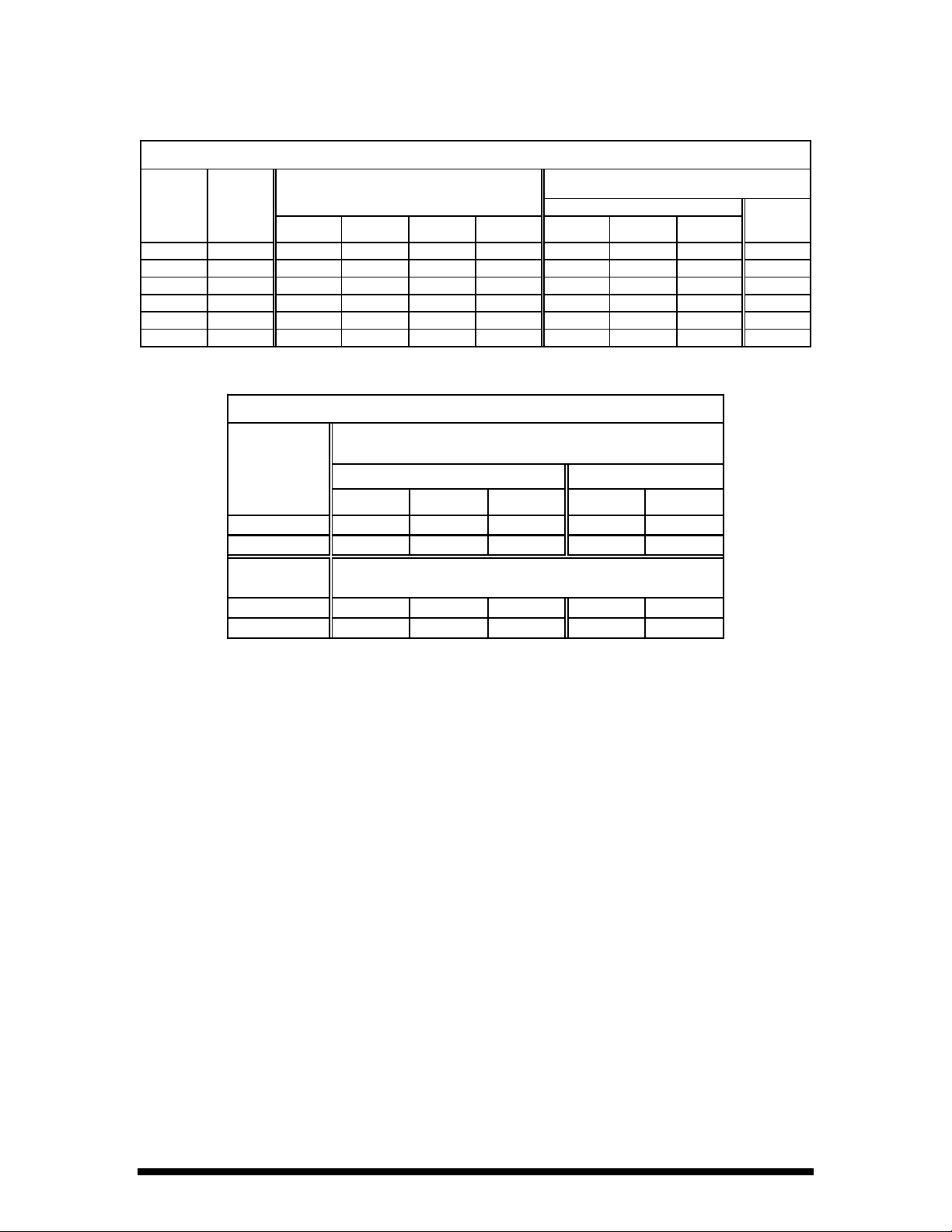
AMPERAGE AND KW CHART
MODEL VOLT KW AMPERAGE
3 PHASE 1 PHASE
L1 TO L2 L2 TO L3 L3 TO L1 TOTAL LINE 1 LINE 2 LINE 3
1 OVEN 208 6.0 2.7 2.7 11.5 36.5 36.5 22.9 55.3
1 OVEN 240 4.2 3.7 3.7 11.5 28.3 28.3 26.5 47.9
1 OVEN 480 6.0 2.7 2.7 11.5 15.6 15.6 10.5 N/A
2 OVENS 208 8.8 8.8 5.5 23.0 59.4 72.9 59.4 110.6
2 OVENS 240 7.8 7.8 7.3 23.0 54.8 56.6 54.8 95.8
2 OVENS 480 8.8 8.8 5.5 23.0 25.5 31.2 25.5 N/A
SERVICE CONNECTION
MODEL FRONT CONNECTION WIRE NUMBERS
3 PHASE 1 PHASE
LINE 1 LINE 2 LINE 3 LINE 1 LINE 2
1 OVEN 1,4 2 3 1,3 2,4
2 OVENS 1,4,7 2,5,8 3,6 1,3,5,7 2,4,6,8
REAR CONNECTION WIRE NUMBERS
1ST OVEN 5,8 6 7 5,7 6,8
2ND OVEN 7 5,8 6 5,7,5,7 6,8,6,8
3
Page 6

GENERAL
OPERATION
Convection ovens constantly circulate air over
and around the product. This strips away the thin
layer of moisture and cool air from around the
product allowing heat to penetrate more quickly.
Cooking times can be shortened and cooking
temperatures can be reduced.
To convert standard deck oven recipes, reduce
the temperature 50 degrees and the time by 25%.
Make minor adjust ments a s necessary.
The lower the oven temperature the more even
the bake.
Check the product near the end of the initial
cooking cycle by turning on the oven light and
looking through t he oven door windows.
CONTROL PANEL
The control panel consist of the following items:
LIGHT SWITCH
POWER SWITCH
STATUS READOUT
Turns the oven interior lights on and off.
Turns the oven on and off.
Displays the oven status (
timer.
Do not open the oven doors during baking as this
will change the baking characteristics of the oven
and make it difficult to determine a final
program.
If the product is overdone on the outside and
underdone on the inside, reduce the baking
temperature.
If the product is pulling away from the edge of
the pan, the temperature is too high or the
cooking time too long.
Load each shelf evenly. Spaces should be
maintained equally between the pan and oven
walls, front and back.
For best baking results, load the oven from the
top to the bottom during random loading.
etc.) and is the count down
TIER LIGHTS
PRODUCT BUTTONS
SHELF BUTTONS
"MAN PROG"
"TEMP"
"READ/CLEA R"
Displays the tier that the program is running, mainly used during
programming.
Numbered 0 to 9 these buttons contain the programs that, when selected,
will run the oven.
Labeled A to E these buttons indicate which shelf the product is placed
on, A being the top shelf.
Short for Manual Program, this button allows the operator to enter a time
and temperature without being required to enter the programming code.
The program is lost once the oven is turned off.
When pushed this button will display the current operating temperature of
the oven in the STATUS READOUT.
Pressing this button twice then pressing a Product button instructs the
oven to "read back" the times and temperatures for that product button in
the STATUS READOUT. It will also switch the oven from a running
program to "
STATUS READOUT
" when pressed and held until " " appears in the
4
Page 7

MANUAL OVERRIDE
Located below the control panel, behind the louvered access door. In the
event of a computer failure, this switch takes control of the oven away
from the computer and directs the temperature control to a manual
thermostat located next to the switch.
BACK-UP THERMOSTAT
Activated when the MANUAL OVERRIDE switch it set to ON. This
thermostat controls the oven temperature in the event of a computer
failure.
STATUS READOUT DISPLAY
The STATUS READOUT informs the operator
of the oven's status.
It can be used as a countdown timer, shelf in use
or internal oven temperature display during the
cooking cycle (see seperate PROGRAMMING
instructions).
"
" The oven is energized and ready for an operator command.
" Stands for PREHEAT. A product has been selected and the oven is
"
heating to the set temperature.
"
" The oven's internal temperature is below what is programmed.
" A product change has been made and the oven's internal temperature is
"
above what is programmed.
"
" A product selection has been made after the oven has preheated and the
computer is asking which shelf the product is placed on.
" " There is a fault in the control system, the computer will not operate until
service is performed.
The STATUS READOUT display informs the
operator when the oven is ready to bake, or if the
oven is above or below the progroammed
temperature.
Below is a list of displays and their definitions:
" " Stands for CONTINOUS. The oven has been programmed without a time
being entered. The oven will operate continuously at the programmed
temperature.
" An entry has been made during the programming which is outside the
"
parametes of the computer.
PRODUCT AND SHELF BUTTONS
Once the PRODUCT BUTTONS are
programmed, all of the oven's operation is
controlled by the computer.
To select a product simply push any of the
programmed PRODUCT BUTTONS which is
labeled for the product you wish to cook.
Once a product button is selected, the oven will
preheat to the preprogrammed temperature.
The control will not allow the operator to select a
shelf until it has reached its programmed
temperature.
Once the programmed temperature is reached the
STATUS READOUT will display "
the beeper will sound briefly.
Only the PRODUCT BUTTONS programmed at
the oven's temperature will now be activated (the
button lamp will be on).
To cook, place the product into the oven cavity
and shut the oven doors. Select the PRODUCT
BUTTON labeled for that product.
" and
5
Page 8

The STATUS READOUT will then display
"
", at that time press the SHELF
BUTTON(S) that match the shelf position(s) the
product was placed on (A equals the top shelf, E
equals the bottom shelf).
If the product program is a MULTIPLE TIERED
program, the operator has only one opportunity
to enter a PRODUCT and SHELF selection. The
computer will not allow a second selection
during the cooking cycle (see seperate
PROGRAMMING instructions).
When the product is done the STATUS
READOUT will display "
sound, and a SHELF BUTTON will flash
indicating which product has finished baking.
Pressing the SHELF BUTTON will turn off the
beeper and allow the oven to continue baking or
go to stand-by with the STATUS READOUT
displaying "
PRODUCT CHANGING
If you wish to change to a product which is
programmed at a different temperature you must
first press the
"
" is displayed in the STATUS
READOUT. Release the
and the STATUS READOUT will display
"
" and allow the selection of the new
product.
When a product which is programmed at a
different temperature is selected, the STATUS
READOUT will display "
oven has reached the programmed temperature.
The computer will not allow a shelf selection
until the STATUS READOUT displays "
Once the computer reaches the programmed
temperature the beeper will sound briefly and the
STATUS READOUT will display "
When the STATUS READOUT displays "
any PRODUCT BUTTON which is programmed
at the same temperature will also light up.
When a PRODUCT button is selected, that
button will flash slowly, indicating which product
is being baked.
".
READ/CLEAR
", the beeper will
button until
READ/CLEAR
" or " " until the
"
button
".
CANCEL SHELF
Press the
the shelf to be canceled. The STATUS
READOUT will display
the next to time to done.
READ/CLEAR
button twice then press
or the time for
MANUAL PROGRAMMING
The button on the control panel labeled
PROG
is the MANUAL PROGRAM button.
The MANUAL PROGRAM (MAN PROG)
button allows the operator in create a short-term
program for one time products.
The program will be erased when the oven is
turned off or the
pushed.
The MANUAL PROGRAM button is active only
when the STATUS READOUT displays "
To operate the MANUAL PROGRAM feature
press the
The STATUS READOUT will display "
Select the desired temperature using the
PRODUCT buttons 0 through 9 to a maximum
of 450 degrees.
Once a temperature is entered the STATUS
READOUT will display "
asking for a co oking time input.
Enter the desired cooking time using the
PRODUCT buttons 0 through 9 to a maximum
of 9:59:59.
If the program does not require a time, press the
flashing E button when the STATUS READOUT
displays "
continuously at the programmed temperature
with the STATUS READOUT displaying "
"
No other buttons will be activated until the oven
has reached the programmed temperature.
Once the oven has reached the programmed
temperature the STATUS READOUT will
display "
all PRODUCT buttons which are programmed at
the same temperature will also flash.
MAN PROG
READ/CLEAR
button.
". The control is
". The oven will run
", the buzzer will sound briefly and
MAN
button is
".
".
".
TIME RECALL
To check the remaining cook time on a product
that is baking, press the corresponding SHELF
button, the STATUS READOUT will display the
remaining time on the cook cycle.
To run the MANUAL PROGRAM, load the
product to be baked.
Press the
READOUT will display "
lights will flash.
MAN PROG
button, the STATUS
" and the shelf
6
Page 9

Press the SHELF button(s) which correspond to
where the product is loaded in the oven (A equals
the top shelf).
When the product is finished baking the beeper
will sound continuously, the STATUS
READOUT will display "
button will flash indicating which shelf is to be
removed from the oven.
", and a SHELF
The STATUS READOUT will scroll through the
product program one entry at a time.
Always start the "read" sequence with the
STATUS READOUT displaying "
It is used during the initial programming to back
up a step if an error is made during the
programming sequence.
".
Press the flashing SHELF button to turn the
beeper off.
To erase a MANUAL PROGRAM press and
hold the
STATUS READOUT displays "
release.
READ/CLEAR
button until the
" then
TEMPERATURE RECALL BUTTON
When pressed, the
actual oven temperature in the STATUS
READOUT.
During the preheat cycle the
cannot be used .
TEMP
button will display the
TEMP
button
READ/CLEAR BUTTON
READ/CLEAR
The
from a run mode to "
operator to select another product which is
programmed at a different temperature.
To change from "
running program, push and hold the
READ/CLEAR
the STATUS READOUT then release the button.
The STATUS READOUT will display "
and the control is ready to accept a new operator
command.
The READ/CLEAR button can also be used to
"read" and existing program.
button will change the oven
", allowing the
" to " " or cancel a
button until "
" appears in
MANUAL CONTROL OVERRIDE
Should the computer control system develop a
fault causing it not to function, the MANUAL
OVERRIDE switch, when energized, will bypass
the computer and change the oven control to a
mechanical thermostat allowing the oven to
continue to operate in a manual mode until
service can be performed on the computer.
The MANUAL OVERRIDE control can also be
used to run the oven until the computer is
programmed.
The switch for the MANUAL OVERRIDE is
located behind the louvered door, below the
control panel.
With the switch in the Off (down) position the
oven is operated by the computer.
With the switch in the On (up) position the oven
is operated by the mechanical thermostat located
just to the left of the switch.
Rotate the thermostat knob clockwise until the
desired temperature appears at the top of the
knob.
When the MANUAL OVERRIDE switch is
"
energized, the computer control panel will turn
off all displays and will not time the product.
If service is required on the Lang computer, refer
to the Lang Authorized Service Agency
Directory for the nearest repair agency.
To "read" and existing program, press the
READ/CLEAR
PRODUCT button to be read.
button twice and then press the
7
Page 10

CLEANING
MAINTENANCE
Always start with a cold oven.
The porcelain or stainless interiors can easily be
cleaned using most domestic or commercial oven
cleaners.
Follow the manufacturer's instructions when
using any cleaner.
Care should be taken to prevent caustic cleaning
compounds from coming in contact with the
blower wheel or the aluminized steel panel
located directly behind the fan baffle.
The oven racks and rack slides may be cleaned
by removing them from the oven and soaking
them in a solution of ammonia and water.
The stainless steel door liners and oven front
should normally be cleaned with a soap and
water solution.
The painted surfaces should also be cleaned with
a mild soap and water solution.
Discoloration or heat tint may be removed with
any of the following cleaners: Penny Brite
Copper Brite
Steel
, Du-Bois Temp, or Past Nu-
.
Always apply these cleaners when the oven is
cold and rub in the direction of the metal's grain.
DOOR CHAIN ADJUSTMENT
WARNING
DISCONNECT THE OVEN FROM POWER
The door chain assembly is located directly
beneath the oven doors, inside the lower trim
piece.
To reach the door chain assembly remove the
three screws holding the bottom trim piece in
place.
Pull the trim piece forward off of the oven.
Adjustment to the door chain assembly is made
by loosening the lock nut on the turnbuckle then
turning the turnbuckle until the door chain is
,
tight and the door without the handle closes just
ahead of the door with the handle.
8
Page 11

SERVICE
WARNING
SERVICE ON THIS, OR ANY OTHER, LANG APPLIANCE MUST BE PERFORMED BY
QUALIFIED PERSONNEL ONLY. CONSULT YOUR AUTHORIZED SERVICE STATION
DIRECTORY OR CALL THE FACTORY AT 206-881-7569 FOR THE SERVICE STATION
NEAREST YOU.
CALIBRATION
The Lang Computerized Convection Oven is
electronically controlled. Calibration of the
control is not necessary nor is it available.
CONTROL PANEL REMOVAL
WARNING
DISCONNECT THE OVEN FROM POWER
Remove the two sheet metal screws going
vertically into the top of the control panel.
Open the oven doors and remove the two screws
holding the lower trim piece in place.
Remove the one sheet metal screw holding the
bottom of the control panel to the lower trim
piece.
Remove the lower trim piece from the oven.
Remove the one sheet metal screw from the
lower right cor ner o f the c o ntr ol p a nel b e hind the
trim piece.
ELEMENT REMOVAL
WARNING
DISCONNECT THE OVEN FROM POWER
Remove the oven racks and rack slides from the
oven cavity.
Remove the four thumb screws located at the
corners of the fan baffle. Remove the fan baffle
from the oven.
Remove the six sheet metal screws holding the
element plate to the back oven wall.
Grasp the oven element and pull the element
forward into the oven cavity.
Remove the wires from the element terminals.
Be sure to note the wire color for proper
replacement on the element.
Reverse the above procedures for installation.
MOTOR REMOVAL
Grasp the control panel assembly and gently pull
it forward on its slide until access is gained to the
control components.
Take care when sliding the control assembly in
or out so as not to snag any wires or kink the
manual thermostat capillary tube.
Reverse the above procedure for installation.
WARNING
DISCONNECT THE OVEN FROM POWER
Remove the oven racks and rack slides from the
oven cavity.
Remove the four thumb screws located at the
corners of the fan baffle. Remove the fan baffle
from the oven.
Remove the eight 1/4 X 20 bolts from the motor
plate located behind the blower wheel.
Grasp the motor plate and slide the entire motor
assembly into the oven compartment.
9
Page 12

Remove the wires from the motor and safety
thermostat. Be sure to mark the wires for proper
replacement.
Loosen the set screws holding the blower fan to
the motor shaft.
Remove the oven racks and rack slides from the
oven cavity.
Remove the four thumb screws located at the
corners of the fan baffle. Remove the fan baffle
from the oven.
Using a three finger wheel puller, grasp the
puller ring on the blower wheel hub and tighten
the puller until the blower comes off of the motor
shaft.
Remove the four 5/16 bolts holding the motor to
the motor mount.
Reverse the above procedure for replacement.
IMPORTANT NOTE
When replacing the blower wheel onto the motor
shaft, locate the blower so the blower hub is flush
with the end of the motor shaft. Adjust the motor
so the blower spins straight with the motor plate
before tightening the motor to the motor mount.
SAFETY THERMOSTAT REMOVAL
WARNING
DISCONNECT THE OVEN FROM POWER
Remove the eight 1/4 X 20 bolts from the motor
plate located behind the blower wheel.
Grasp the motor plate and slide the entire motor
assembly into the oven compartment.
Remove the wires from the safety thermostat. Be
sure to mark the wires for proper replacement.
Remove the screws holding the safety thermostat
bracket to the motor plate.
Remove the safety thermostat bracket from the
motor plate.
Remove the screws holding the safety thermostat
to the bracket.
Remove the safety thermostat from the bracket.
Reverse the above procedure for replacement.
10
Page 13

PARTS
CONTROL PANEL LAYOUT
ITEM NO. DESCRIPTION ITEM NO. DESCRIPTION
1 Touch control panel 6 Manual override switch
G - Temperature sensor connection
H - Output to contactors 8 Heat contactor
2 Microprocessor 9 Motor contactor
A - 12 volt supply 10 Manual override relay
B - Ribbon connectors 11 Terminal block
3 Beeper board 12 12 volt transformer
4 Power switch 13 24 volt transformer
5 Manual override thermostat 14 Light switch
11
Page 14

PARTS LIST
DESCRIPTION PART #
Bulb Socket: Oven Lamp 31602-04
Bulb: Oven Lamp 31603-04
Circuit Board Assembly: Buzzer 40102-10
Circuit Board Assembly: Front Panel 40102-08
Circuit Board Assembly: Microprocessor 40102-11
Circuit Breaker: 1 Pole 31800-01
Circuit Breaker: 3 Pole (480 Volt Units Only) 31800-04
Contactor: 2 Pole, 24 Volt Coil, 2 Speed Motor 30701-05
Contactor: 3 Pole, 24 Volt Coil, Motor/Element 30700-06
Element: Oven Heating, 208/240 Volt 11090-16
Element: Oven Heating, 480 Volt 11090-18
Fan: Convection Blower 71500-05
Fuse Holder: 15 Amp Fuse 30901-08
Fuse: Control, 15 Amp 30900-10
Handle: Oven Door 70603-15
Knob: Damper 70701-25
Knob: Manual Override Thermostat 70701-19
Motor: Convection Fan, 208/240 Volt 30200-17
Motor: Convection Fan, 480 Volt 30200-16
Rack Slide: Oven Interior 50200-32
Rack: Oven Interior 50200-59
Relay: Manual Override 30600-02
Sensor: Oven Temperature 41100-08
Switch: Micro, Oven Door 30301-02
Switch: Toggle, On-Off 30303-06
Switch: Toggle, Oven Lights 30303-07
Switch: Toggle, Manual Override 30303-06
Thermostat: Hi Limit 30401-09
Thermostat: Manual Override 30402-27
Transformer: 240/12 31400-12
Transformer: 240/24 31400-10
Transformer: 480/240 (480 Volt Units Only) 31400-04
Window: Oven Door 71301-04
12
Page 15

208 /240 VOLT
WIRING DIAGRAMS
13
Page 16

480 VOLT OVEN
14
 Loading...