

Page 1
Installation, Operation, Maintenance, & Troubleshooting
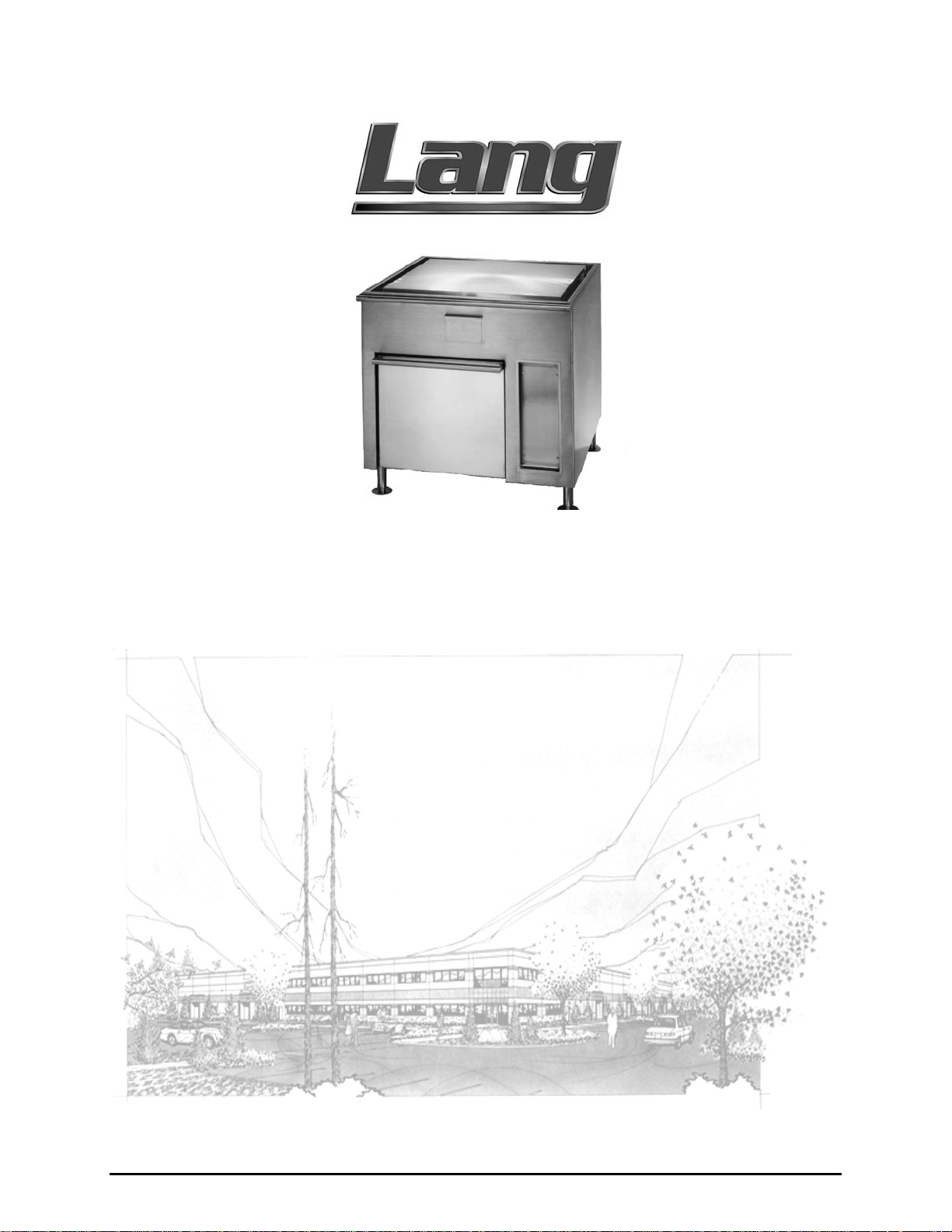
Model: CLR36R-GB-S
Overhead Switchbox
Serial:
Electric Cruise Line Grooved Griddle Range with an
Lang Manufacturing Company 6500 Merrill Creek Parkway Everett, WA 98203
Phone: 425-349-2400 Fax: 425-349-2733
WWW.LANGWORLD.COM © Copyright 2000
Page 2

THIS MANUAL MUST BE RETAINED FOR FUTURE REFERENCE.
READ, UNDERSTAND AND FOLLOW THE INSTRUCTIONS AND
WARNINGS CONTAINED IN THIS MANUAL.
FOR YOUR SAFETY
DO NOT STORE OR USE GASOLINE OR OTHER FLAMMABLE
VAPORS AND LIQUIDS IN THE VICINITY OF THIS OR ANY
OTHER APPLIANCE.
WARNING: IMPROPER INSTALLATION, ADJUSTMENT,
ALTERATION, SERVICE OR MAINTENANCE CAN CAUSE
PROPERTY DAMAGE, INJURY OR DEATH. READ THE
INSTALLATION, OPERATING AND MAINTENANCE
INSTRUCTIONS THOROUGHLY BEFORE INSTALLING OR
SERVICING THIS EQUIPMENT.
NOTICE:
VESSELS GREATER THAN 65 FEET IN LENGTH, IN ACCORDANCE WITH
USCG REGULATIONS IN TITLE 46 CFR 110-113. ANY WIRING USED IN
THE INSTALLATION OF THIS APPLAINCE MUST BE STRANDED COPPER.
THIS EQUIPMENT IS APPROVED FOR INSTALLATION ONLY ON
2
Page 3

TABLE OF CONTENTS
CHAPTER PAGE
1. TABLE OF CONTENTS................................................................................3
2. READ FIRST..................................................................................................4
3. UNPACKING.................................................................................................6
4. INSTALLATION............................................................................................7
5. INITIAL START-UP......................................................................................8
6. OPERATION..................................................................................................9
7. CLEANING.................................................................................................... 10
8. TROUBLESHOOTING..................................................................................11
9. PARTS LISTS.................................................................................................13
10. EXPLODED VIEWS......................................................................................15
11. WIRING DIAGRAMS....................................................................................21
12. WARRANTY..................................................................................................22
3
Page 4
IMPORTANT READ FIRST IMPORTANT
CAUTION:
CAUTION:
DANGER:
.
WARNING:
NOTICE:
THE RANGE WEIGHS 600 LBS. (272.16 KILOGRAMS).
FOR SAFE HANDLING, INSTALLER SHOULD OBTAIN
HELP AS NEEDED, OR EMPLOY APPROPR IATE
MATERIALS HANDLING EQUIPMENT (SUCH AS A
FORKLIFT, DOLLY, OR PALLET JACK) TO REMOVE
THE UNIT FROM THE SKID AND MOVE IT TO THE
PLACE OF INSTALLATION.
ANY STAND, COUNTER OR OTHER DEVICE ON
WHICH RANGE WILL BE LOCATED MUST BE
DESIGNED TO SUPPORT THE WEIGHT OF THE
RANGE (600 LBS.).
THIS APPLIANCE MUST BE GROUNDED AT THE
TERMINAL PROVIDED. FAILURE TO GROUND THE
APPLIANCE COULD RESULT IN ELECTROCUTION
AND DEATH.
INSTALLATION OF THE UNIT MUST BE DONE BY
PERSONNEL QUALIFIED TO WORK WITH
ELECTRICITY. IMPROPER INSTALLATION CAN
CAUSE INJURY TO PERSONNEL AND/OR DAMAGE
TO EQUIPMENT. UNIT MUST BE INSTALLED IN
ACCORDANCE WITH ALL APPLICABLE CODES.
The data plate is located behind the access cover to
the right of the oven door. The range voltage,
wattage, serial number, wire size, and clearance
specifications are on the data plate. This information
should be carefully read and understood before
proceeding with the installation.
NOTICE:
CAUTION:
CAUTION:
The installation of any components such as a vent
hood, grease extractors, fire extinguisher systems,
must conform to their applicable National, State and
locally recognized installation standards.
ALWAYS KEEP THE AREA NEAR THE APPLIANCE
FREE FROM COMBUSTIBLE MATERIALS.
KEEP FLOOR IN FRONT OF EQUIPMENT CLEAN
AND DRY. IF SPILLS OCCUR, CLEAN IMMEDIATELY,
TO AVOID THE DANGER OF SLIPS OR FALLS.
4
Page 5
IMPORTANT READ FIRST IMPORTANT
WARNING:
CAUTION:
NOTICE:
WARNING:
CAUTION:
KEEP WATER AND SOLUTIONS OUT OF CONTROLS.
NEVER SPRAY OR HOSE CONTROL CONSOLE,
ELECTRICAL CONNECTIONS, ETC.
MOST CLEANERS ARE HARMFUL TO THE SKIN, EYES,
MUCOUS MEMBRANES AND CLOTHING.
PRECAUTIONS SHOULD BE TAKEN TO WEAR RUBBER
GLOVES, GOGGLES OR FACE SHIELD AND
PROTECTIVE CLOTHING. CAREFULLY READ THE
WARNING AND FOLLOW THE DIRECTIONS ON THE
LABEL OF THE CLEANER TO BE USED.
Service on this, or any other, LANG appliance must be
performed by qualified personnel only. Consult your
authorized service station directory or call the factory at
1-800-224-LANG (5264), or WWW.LANGWORLD.COM for
the service station nearest you.
BOTH HIGH AND LOW VOLTAGES ARE PRESENT
INSIDE THIS APPLIANCE WHEN THE UNIT IS
PLUGGED/WIRED INTO A LIVE RECEPTACLE. BEFORE
REPLACING ANY PARTS, DISCONNECT THE UNIT
FROM THE ELECTRIC POWER SUPPLY.
USE OF ANY REPLACEMENT PARTS OTHER THAN
THOSE SUPPLIED BY LANG OR THEIR AUTHORIZED
DISTRIBUTORS CAN CAUSE BODILY INJURY TO THE
OPERATOR AND DAMAGE TO THE EQUIPMENT AND
WILL VOID ALL WARRANTIES.
5
Page 6

3.1 Receiving the Range
Upon receipt, check for freight damage, both visible and concealed. Visible
damage should be noted on the freight bill at the time of delivery and signed by the
carrier's agent. Concealed loss or damage means loss or damage, which does not
become apparent until the merchandise has been unpacked. If concealed loss or
damage is discovered upon unpacking, make a written request for inspection by the
carrier's agent within 15 days of delivery. All packing material should be kept for
inspection. Do not return damaged merchandise to Lang Manufacturing Company.
File your claim with the carrier.
3.2 Location
Prior to un-crating, move the range as near its intended location as practical. The
crating will help protect the unit from the physical damage normally associated
with moving it through hallways and doorways.
3.3 Un-crating
Uncrate range as close to installation location as possible. The range is packaged
on a pallet, wrapped in plastic to protect the unit from moisture and surrounded by
a wooden frame. Remove the wood crating carefully. Improper use of tools can
result in damage to the equipment. Remove and discard the plastic wrap.
Desiccant bags on top of the range should also be discarded. Protective paper on
top of the range may be left until the installation is complete.
UNPACKING
The range is raised on blocks to enable ease of handling when removing from pallet
with forklift or straps. Use extreme care regardless of method used and be aware of
gravity center, especially with banks of multiple units.
PLEASE NOTE:
Legs, manuals, racks, rack slides, griddle cleaning tools, fryer smother covers and
remote overhead switch boxes, where applicable, are packed inside the oven cavity
and should remain there until the unit is at the final installation location.
Desiccant bags have been placed inside electrical cavity and must be removed
before operation.
CAUTION:
CAUTION:
RANGE WEIGHS 600 LBS (272.16 kilograms). FOR
SAFE HANDLING, INSTALLER SHOULD OBTAIN HELP
AS NEEDED, OR EMPLOY APPROPRIATE MATERIALS
HANDLING EQUIPMENT (SUCH AS A FORKLIFT,
DOLLY, OR PALLET JACK) TO REMOVE THE UNIT
FROM THE SKID AND MOVE IT TO THE PLACE OF
INSTALLATION.
ANY STAND, COUNTER OR OTHER DEVICE ON WHICH
RANGE WILL BE LOCATED MUST BE DESIGNED TO
SUPPORT THE WEIGHT OF THE RANGE (600 LBS.).
6
Page 7
INSTALLATION
DANGER:
WARNING:
NOTICE:
NOTICE:
THIS APPLIANCE MUST BE GROUNDED AT THE
TERMINAL PROVIDED. FAILURE TO GROUND THE
APPLIANCE COULD RESULT IN ELECTROCUTION AND
DEATH.
INSTALLATION OF THE UNIT MUST BE DONE BY
PERSONNEL QUALIFIED TO WORK WITH ELECTRICITY.
IMPROPER INSTALLATION CAN CAUSE INJURY TO
PERSONNEL AND/OR DAMAGE TO EQUIPMENT. UNIT
MUST BE INSTALLED IN ACCORDANCE WITH ALL
APPLICABLE CODES.
The data plate is located behind the access cover to the
right of the oven door. The range voltage, wattage, serial
number, wire size, and clearance specifications are on the
data plate. This information should be carefully read and
understood before proceeding with the installation.
The installation of any components such as a vent hood,
grease extractors, fire extinguisher systems, must
conform to their applicable National, State and locally
recognized installation standards.
4.1 Electrical Connection with an Overhead Switch Box
Electrical connection must be accomplished with 3 separate connections on remote
switch box, and 2 connections on the range. Connection #1 is for incoming power.
Connection #2 is for wires connecting switch box to range. Connection #3 is for
probe wires only. The probe wires must be connected from the range to the switch
box with a shielded cable. Grounded at one end only, running in a separate
conduit. Connections for the range are made on the terminal block located behind
an access panel to the right of the oven door. Recommend conduit be hooked into
the bottom front, below the terminal block, or at the right back of the unit behind
the terminal block.
4.2 Overhead Switch Box
The overhead switch box can be mounted anywhere above the range. The
electrical service connection can by made anywhere on the body of the switch box.
4.3 Range Voltage
The Lang Model CLR36R-GB-S can be operated on 440 Volts.
7
Page 8

5.1 PRE-POWER ON
Initial Start-up
Before the initial use of the range, the oven must be thoroughly allowed to dry
itself out. This is done be setting the thermostat to 350°. Allow the range oven to
heat until all vapor and condensation has been eliminated. For best results allow
the oven to thoroughly dry out. Allow 8 to 12 hours for this process. Clean top
plates thoroughly. Apply salad oil. Turn each plate thermostat to a low position
and allow plate to heat for three hours.
INITIAL START UP
NOTICE:
Somewhere along the rising temperature curve between
200
and 300
°°°°
in and around the Range. The smoke may be repeated
somewhere around 350
accumulated during manufacturing may be coming off as
smoke in these temperature ranges. Do no be alarmed.
a moderate amount of smoke may issue from
°°°°
. Preservation oils and oil
°°°°
5.2 Season the Grill
The cooking surface must be "seasoned" in order to reduce product sticking.
To season, heat the griddle to 250 degrees.
Once at 250 degrees, coat the cooking surface with a non-salted vegetable oil.
Allow the griddle to stand at 250 degrees until the cooking surface looks dry then
coat it again.
Heat the griddle to 350 degrees and repeat the procedure.
The griddle may emit a small amount of smoke as the cooking surface passes the
350° point. Do not be alarmed as oils associated with the manufacturing process
may cause smoke and will stop when the griddle reaches 350 degrees.
8
Page 9

OPERATION
CAUTION:
CAUTION:
ALWAYS KEEP THE AREA NEAR THE APPLIANCE
FREE FROM COMBUSTIBLE MATERIALS.
KEEP FLOOR IN FRONT OF EQUIPMENT CLEAN AND
DRY. IF SPILLS OCCUR, CLEAN IMMEDIATELY, TO
AVOID THE DANGER OF SLIPS OR FALLS.
6.1 Range Controls with a Overhead Switch Box
Turn the griddle thermostat dial to the desired temperature setting. The power
switch, located on the control box on the right of the switch box, energizes the
control circuits. When this switch is on, the “power” pilot lamp will be illuminated.
This control is located to the left of the power switch, the left most knob is the left
side of the griddle, and the right one is the right side of the griddle. The “heat” pilot
lamp will illuminate indicating power is applied to the heating elements.
6.2 Oven Controls
The oven must be thoroughly preheated before satisfactory baking can be done.
The oven will not bake uniformly if not sufficiently preheated. After preheating let
the oven cycle 2 or 3 times to ensure complete heating of the entire oven cavity.
The “Roasting and Baking” oven is equipped with a removable rack. For baking
pies, bread, or for roasting operations, the rack may be placed directly on the metal
deck and the pans placed on the rack. For baking cakes or pastries the rack should
be located in the lower position provided by the rack supports at the sides of the
range and the pans placed on the rack in this lower position.
NOTE: Always place the pans symmetrically on the rack for best results. Keep the
oven door closed as much as possible. Excessive door opening will cool the front
section of the oven and products placed near the front are likely to bake slower. It
is desirable to keep the front edge of the pans at least several inches back from the
inside of the door (when closed). Do not permit air from a window or fan to blow
into the oven; it will cause uneven heating.
9
Page 10

WARNING: KEEP WATER AND SOLUTIONS OUT OF CONTROLS.
NEVER SPRAY OR HOSE CONTROL CONSOLE,
ELECTRICAL CONNECTIONS, ETC.
CLEANING
CAUTION:
MOST CLEANERS ARE HARMFUL TO THE SKIN,
EYES, MUCOUS MEMBRANES AND CLOTHING.
PRECAUTIONS SHOULD BE TAKEN TO WEAR
RUBBER GLOVES, GOGGLES OR FACE SHIELD AND
PROTECTIVE CLOTHING. CAREFULLY READ THE
WARNING AND FOLLOW THE DIRECTIONS ON THE
LABEL OF THE CLEANER TO BE USED.
7.1 After each meal Cleaning
Empty the grease drawer often or whenever it is 3/4 full. Remove the grease drawer
after each meal and wash the inside and outside of the drawer.
Keep the griddle surface clean. After each cooking load, scrape the griddle surface
with the grooved griddle cleaning tool to remove any carbonized grease.
The griddle surface should be cleaned and re-seasoned. Use a griddle stone,
griddle pad, or liquid cleaner. Rub with the grain of the metal, being careful not to
scrape the splashguard.
Clean the exterior of the appliance with a hot water and chlorine solution to
maintain a gleaming appearance.
Be sure to rinse thoroughly and coat the cooking surface with a thin film of oil to
prevent rusting.
Re-season the griddle plate after each cleaning (refer to page 8).
7.2 Daily
The range should be thoroughly cleaned at least once a day in addition to the
normal after meal cleaning to insure against the accumulation of foreign material.
Keep the inside of the oven and metal deck clean, particularly around door
opening, door edges and at bottom of door opening so that the door may close
tightly.
10
Page 11

TROUBLESHOOTING
9.1 Symptoms
What follows is a chart of Symptoms and Possible Causes to aid in diagnosing
faults with the oven.
Refer to the Symptoms column to locate the type of failure then to the Possible
Cause for the items to be checked.
To test for a possible cause, refer to the TEST section and locate the Possible Cause
then refer to test to identify test procedures.
SYMPTOM POSSIBLE CAUSE
Indicator is not lit.
Range will not heat
Product burning
Product under done
•
No power to unit
•
Failed switch
•
Failed pilot light
•
Failed element
•
Switch is not ON
•
Failed contactor
•
Failed thermostat/circuit board
•
Failed transformer
•
Open in wiring between switch box and
range
•
Open in terminal block
•
Product is cooked too long
•
Failed thermostat/circuit board
•
Failed contactor
•
Failed temperature sensor
•
Failed circuit board/thermostat
•
Failed temperature selector
11
Page 12

TROUBLESHOOTING CONT’D
9.2 TESTS
NOTICE:
WARNING:
If an item on the list is followed by an asterisk (*), the work should be done by a factory
authorized service representative.
Service on this, or any other, LANG appliance must be
performed by qualified personnel only. Consult your
authorized service station directory or call the factory
at 1-800-224-LANG (5264), or WWW.LANGWORLD.COM
for the service station nearest you.
BOTH HIGH AND LOW VOLTAGES ARE PRESENT
INSIDE THIS APPLIANCE WHEN THE UNIT IS
PLUGGED/WIRED INTO A LIVE RECEPTACLE.
BEFORE REPLACING ANY PARTS, DISCONNECT THE
UNIT FROM THE ELECTRIC POWER SUPPLY.
Possible Cause TEST
Product is cooked too long
Failed thermostat
Failed element
Failed heat contactor
Failed temperature sensor
Failed pilot light
Failed transformer
CAUTION:
USE OF ANY REPLACEMENT PARTS OTHER THAN
THOSE SUPPLIED BY LANG OR THEIR AUTHORIZED
DISTRIBUTORS CAN CAUSE BODILY INJURY TO THE
OPERATOR AND DAMAGE TO THE EQUIPMENT AND
WILL VOID ALL WARRANTIES.
•
No test available, operational condition
•
Check poles on thermostat for continuity
•
Remove the wires and check for continuity
across the element
•
Remove the wires from the contactor coil and
check for continuity across the contactor coil
connection
•
Ensure the contactor moveable points move
freely up and down
•
Check for 24 volts at the contactor coil when
the computer is running
•
Check resistance of sensor for accuracy
•
Check light for resistance
•
Check coils on transformer for correct
resistance
*
12
Page 13

CLR36R-G-S
PARTS LIST
Item # Description
Part
Number
1 Body CLR-003 1
2 Vent Back CLR-529 1
3 Grease Bucket Assembly CLR-500 1
4 Can Assembly CLR-001 1
5 Heat Shield CLR-440 1
6 Door Assembly CLR-002 1
7 Stainless Steel Jam Nut, 5/8-18 20303-14 2
8 CLR Top Element, 440V, 1500W 11045-06 1
9 Probe Shield CLR-424 1
10 CLR Bottom Element, 440V 11045-07 1
11 Element Cover CLR-447 1
12 Element Channel CLR-444 3
13 Spring Tube Cover CLR-484-1 1
14 12 1/4” Stainless Steel Hex Head Cap Screw, 3/8-16 20104-53 1
15 Spring Piston XLHCL-119 1
Qty
16 Hood Type Compression Spring 51002-01 1
17 Spring Tube Assembly CLR-480 1
18 Spring Tube Cap and Bearing Retainer CLR-482 1
19 Door Spring CLR-490 1
20 Door Lever and Shaft CLR-460 1
21 6 1/2” Stainless Steel Hex Head Cap Screw, 1/4-20 20903-03 1
22 Stainless Steel Washer, 1 OD X .638 ID X .125 Thick 20203-09 2
23 Flanged Bronze Bushing, 5/8 ID X 3/4 OD X 5/8 Long 70201-06 2
24 Blank Switch Panel CLR-530 1
25 Oven Element Cover CLR-273 1
26 Cover CLR-272 1
27 Temperature Probe 41100-08 1
28 1 3/8” Heyco Bushing 70801-02 1
29 Overhead Switch Box Assembly OSB-200 1
13
Page 14

PARTS LIST CONT’D
CLR36R-G-S
30 Component Mount OSB-209 1
31 10 Pole Terminal Strip, 30A, 600V 30500-04 4
32 2 Pole Contactor, 30A, 24VAC 30701-04 1
33 Transformer, 480/24 VAC 31400-15 1
34 Black Knob 70701-28 5
35 Pilot Light 31601-07 1
36 Contact Block 30304-31 1
37 2 Position Rotary Switch 30304-30 1
38 Selectronic Probe 41100-17 2
39 3 Heat Rotary Switch, 240/480VAC, 15A 30304-06 4
40 Griddle Control Panel OSB-235 1
41 Griddle Plate – specify top grooves location if desired CLR-520 1
42 Element Pan CLR-513 4
43 Inner Element, 440V, 1850W 11045-09 4
44 Outer Element, 440V, 1650W 11045-08 4
45 Element Plate CLR-511 4
46 Element Plate Support CLR-512 12
47 Element Plate Spacer CLR-514 24
48 Insulation Kit 60106-45 1
49 2 Pole Terminal Strip, 30A, 300V 30500-01 2
50 Trimlock CLR-542 2
51 Two Hole Grounding Lug 31200-08 1
52 Oven Harness CLR-552 1
53 Jumper CLR-553 4
54 Griddle Element Harness for OSB unit CLR-554 2
55 Griddle Oven Control Harness for OSB CLR-556 1
56 Griddle Power Harness for OSB CLR-558 1
57 Temperature Control Circuit Board 40101-18 3
14
Page 15

15161718192021
Page 16

Page 17

Page 18

Page 19

Page 20

Page 21

WIRING DIAGRAM
Page 22

Lang Manufacturing Limited Warranty
to Cruise Line Purchasers
WARRANTY
Lang Manufacturing Equipment (“Lang
Equipment”) has been skillfully manufactured,
carefully inspected and packaged to meet rigid
standards of excellence. Lang warrants its
Equipment to be free from defects in material and
material-related workmanship for (13) thirteen
consecutive months from the date of initial
shipboard installation or (18) eighteen consecutive
months from date of initial factory shipment, which
ever comes first. The aforementioned warranty
statement is subject to the following conditions and
limitations.
I. This warranty is limited to the provision of
replacement components for Product sold by Lang to
a joiner company for installation aboard a cruise
ship, or a cruise ship company for installation aboard
its own ship. The provision of replacement
components to affect Product repairs will be on a nocharge basis during the term of the warranty.
Replacement components will be sent to the address
required within 48 hours of Lang receiving written
notification of the description of the defect and the
model and serial number of the Product affected by
the repair.
Quartz elements are warranted for ninety (90) days
from the date of installation.
II. Damage during shipment is to be reported to the
carrier, is not covered under this warranty, and is the
sole responsibility of purchaser/user.
III. Replacement components will be shipped
F.O.B. factory with freight prepaid.
Replacement component damage related to
shipment is not covered under this warranty.
IV. This warranty does not co ver consumable
parts such as quartz elements, and does not
cover defects caused by improper installation,
abuse, careless operation, or improper
maintenance of Product.
V. All warranties are conditioned upon
Lang’s receipt of written notice of any defect
prior to the end of the applicable warranty
period.
VI.
THIS WARRANTY IS EXCLUSIVE AND IS
IN LIEU OF ALL OTHER WARRANTIES,
EXPRESSED OR IMPLIED, INCLUDING ANY
IMPLIED WARRANTY OF
MERCHANTABILITY OR FITNESS FOR A
PARTICULAR PURPOSE, EACH OF WHICH IS
HEREBY EXPRESSLY DISCLAIMED. THE
REMEDIES DESCRIBED ABOVE ARE
EXCLUSIVE AND IN NO EVENT SHALL LANG
BE LIABLE FOR SPECIAL, CONSEQUENTIAL
OR INCIDENTAL DAMAGES FOR THE
BREACH OR DELAY IN PERFORMANCE OF
THIS WARRANTY.
VII. Lang Equipment is for cruise line use only. If
sold as a component of another (OEM)
manufacturer’s equipment, or if used as a consumer
product, such Equipment is sold AS IS and without
any wa r ranty.
19
 Loading...