

Page 1
Installation, Operation, Maintenance, & Troubleshooting
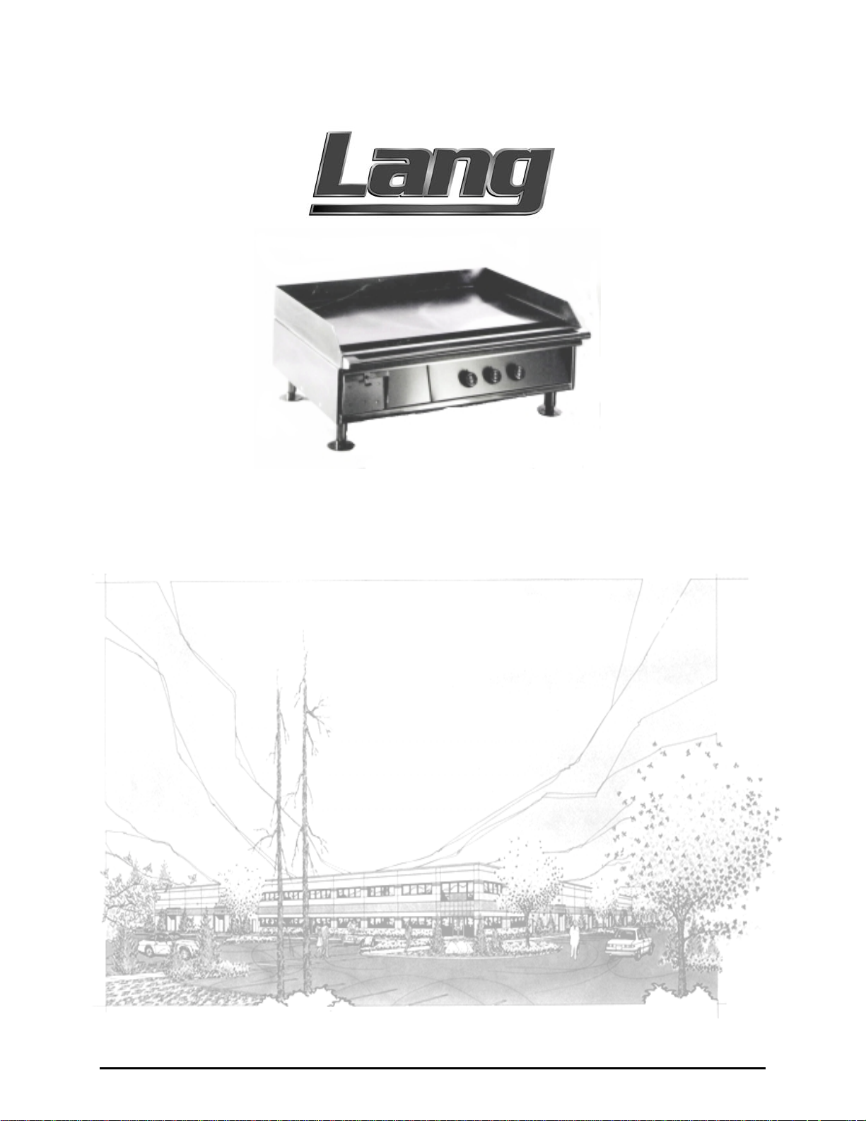
Model: CLG-36-S
Serial:
Electric Cruise Line Griddle
Lang Manufacturing Company 6500 Merrill Creek Parkway Everett, WA 98203
Phone: 425-349-2400 Fax: 425-349-2733
WWW.LANGWORLD.COM © Copyright 2000
Page 2

THIS MANUAL MUST BE RETAINED FOR FUTURE REFERENCE.
READ, UNDERSTAND AND FOLLOW THE INSTRUCTIONS AND
WARNINGS CONTAINED IN THIS MANUAL.
FOR YOUR SAFETY
DO NOT STORE OR USE GASOLINE OR OTHER FLAMMABLE
VAPORS AND LIQUIDS IN THE VICINITY OF THIS OR ANY
OTHER APPLIANCE.
WARNING: IMPROPER INSTALLATION, ADJUSTMENT,
ALTERATION, SERVICE OR MAINTENANCE CAN CAUSE
PROPERTY DAMAGE, INJURY OR DEATH. READ THE
INSTALLATION, OPERATING AND MAINTENANCE
INSTRUCTIONS THOROUGHLY BEFORE INSTALLING OR
SERVICING THIS EQUIPMENT.
NOTICE:
THIS EQUIPMENT IS APPROVED FOR INSTALLATION ONLY ON
VESSELS GREATER THAN 65 FEET IN LENGTH, IN
ACCORDANCE WITH USCG REGULATIONS IN TITLE 46 CFR
110-113. ANY WIRING USED IN THE INSTALLATION OF THIS
APPLAINCE MUST BE STRANDED COPPER.
2
Page 3

TABLE OF CONTENTS
CHAPTER PAGE
1. TABLE OF CONTENTS................................................................................3
2. READ FIRST..................................................................................................4
3. UNPACKING.................................................................................................6
4. INSTALLATION............................................................................................7
5. INITIAL START-UP......................................................................................8
6. OPERATION..................................................................................................9
7. MAINTENANCE & CLEANING PROCEDURES......................................10
8. TROUBLESHOOTING..................................................................................11
9. PARTS LIST...................................................................................................13
10. EXPLODED VIEWS......................................................................................14
11. WIRING DIAGRAM......................................................................................18
12. WARRANTY..................................................................................................19
3
Page 4
IMPORTANT READ FIRST IMPORTANT
CAUTION:
CAUTION:
CAUTION:
DANGER:
WARNING:
GRIDDLE WEIGHS 405 lbs (183.71 kg) . FOR SAFE
HANDLING, INSTALLER SHOULD OBTAIN HELP AS
NEEDED, OR EMPLOY APPROPRIATE MATERIALS
HANDLING EQUIPMENT (SUCH AS A FORKLIFT,
DOLLY, OR PALLET JACK) TO REMOVE THE UNIT
FROM THE SKID AND MOVE IT TO THE PLACE OF
INSTALLATION.
ANY STAND, COUNTER OR OTHER DEVICE ON
WHICH GRIDDLE WILL BE LOCATED MUST BE
DESIGNED TO SUPPORT THE WEIGHT OF THE
GRIDDLE.
SHIPPING STRAPS ARE UNDER TENSION AND CAN
SNAP BACK WHEN CUT.
THIS APPLIANCE MUST BE GROUNDED AT THE
TERMINAL PROVIDED. FAILURE TO GROUND THE
APPLIANCE COULD RESULT IN ELECTROCUTION
AND DEATH.
INSTALLATION OF THE UNIT MUST BE DONE BY
PERSONNEL QUALIFIED TO WORK WITH
ELECTRICITY. IMPROPER INSTALLATION CAN
CAUSE INJURY TO PERSONNEL AND/OR DAMAGE
TO EQUIPMENT. UNIT MUST BE INSTALLED IN
ACCORDANCE WITH ALL APPLICABLE CODES.
NOTICE:
NOTICE:
CAUTION:
CAUTION:
The data plate is located behind the access panel in
the back of the griddle. The griddle voltage, wattage,
serial number, wire size, and clearance specifications
are on the data plate. This information should be
carefully read and understood before proceeding
with the installation.
The installation of any components such as a vent
hood, grease extractors, fire extinguisher systems,
must conform to their applicable National, State and
locally recognized installation standards.
ALWAYS KEEP THE AREA NEAR THE APPLIANCE
FREE FROM COMBUSTIBLE MATERIALS.
KEEP FLOOR IN FRONT OF EQUIPMENT CLEAN
AND DRY. IF SPILLS OCCUR, CLEAN IMMEDIATELY,
TO AVOID THE DANGER OF SLIPS OR FALLS.
4
Page 5
IMPORTANT READ FIRST IMPORTANT
WARNING:
CAUTION:
NOTICE:
WARNING:
CAUTION:
KEEP WATER AND SOLUTIONS OUT OF CONTROLS.
NEVER SPRAY OR HOSE CONTROL CONSOLE,
ELECTRICAL CONNECTIONS, ETC.
MOST CLEANERS ARE HARMFUL TO THE SKIN, EYES,
MUCOUS MEMBRANES AND CLOTHING.
PRECAUTIONS SHOULD BE TAKEN TO WEAR RUBBER
GLOVES, GOGGLES OR FACE SHIELD AND
PROTECTIVE CLOTHING. CAREFULLY READ THE
WARNING AND FOLLOW THE DIRECTIONS ON THE
LABEL OF THE CLEANER TO BE USED.
Service on this, or any other, LANG appliance must be
performed by qualified personnel only. Consult your
authorized service station directory or call the factory at
1-800-224-LANG (5264), or
for the service station nearest you.
BOTH HIGH AND LOW VOLTAGES ARE PRESENT
INSIDE THIS APPLIANCE WHEN THE UNIT IS
PLUGGED/WIRED INTO A LIVE RECEPTACLE. BEFORE
REPLACING ANY PARTS, DISCONNECT THE UNIT
FROM THE ELECTRIC POWER SUPPLY.
USE OF ANY REPLACEMENT PARTS OTHER THAN
THOSE SUPPLIED BY LANG OR THEIR AUTHORIZED
DISTRIBUTORS CAN CAUSE BODILY INJURY TO THE
OPERATOR AND DAMAGE TO THE EQUIPMENT AND
WILL VOID ALL WARRANTIES.
WWW.LANGWORLD.COM
5
Page 6
3.1 Receiving the Griddle
Upon receipt, check for freight damage, both visible and concealed. Visible
damage should be noted on the freight bill at the time of delivery and signed by the
carrier's agent. Concealed loss or damage means loss or damage which does not
become apparent until the merchandise has been unpacked. If concealed loss or
damage is discovered upon unpacking, make a written request for inspection by the
carrier's agent within 15 days of delivery. All packing material should be kept for
inspection. Do not return damaged merchandise to Lang Manufacturing Company.
File your claim with the carrier.
3.2 Location
Prior to un-crating, move the griddle as near its intended location as practical. The
crating will help protect the unit from the physical damage normally associated
with moving it through hallways and doorways.
3.3 Un-crating
The griddle will arrive completely assembled inside a wood frame covered by
cardboard box and strapped to a skid.
straps and remove the wood frame.
Remove the cardboard cover, cut the
UNPACKING
CAUTION:
CAUTION:
CAUTION:
Remove griddle from skid and place in intended location.
GRIDDLE WEIGHS 405 lbs (183.71 kg). FOR SAFE
HANDLING, INSTALLER SHOULD OBTAIN HELP AS
NEEDED, OR EMPLOY APPROPRIATE MATERIALS
HANDLING EQUIPMENT (SUCH AS A FORKLIFT,
DOLLY, OR PALLET JACK) TO REMOVE THE UNIT
FROM THE SKID AND MOVE IT TO THE PLACE OF
INSTALLATION.
ANY STAND, COUNTER OR OTHER DEVICE ON WHICH
GRIDDLE WILL BE LOCATED MUST BE DESIGNED TO
SUPPORT THE WEIGHT OF THE GRIDDLE.
SHIPPING STRAPS ARE UNDER TENSION AND CAN
SNAP BACK WHEN CUT.
6
Page 7

INSTALLATION
DANGER:
WARNING:
NOTICE:
NOTICE:
THIS APPLIANCE MUST BE GROUNDED AT THE
TERMINAL PROVIDED. FAILURE TO GROUND THE
APPLIANCE COULD RESULT IN ELECTROCUTION AND
DEATH.
INSTALLATION OF THE UNIT MUST BE DONE BY
PERSONNEL QUALIFIED TO WORK WITH ELECTRICITY.
IMPROPER INSTALLATION CAN CAUSE INJURY TO
PERSONNEL AND/OR DAMAGE TO EQUIPMENT. UNIT
MUST BE INSTALLED IN ACCORDANCE WITH ALL
APPLICABLE CODES.
The data plate is located behind the access panel in the
back of the grill. The griddle voltage, wattage, serial
number, wire size, and clearance specifications are on the
data plate. This information should be carefully read and
understood before proceeding with the installation.
The installation of any components such as a vent hood,
grease extractors, fire extinguisher systems, must
conform to their applicable National, State and locally
recognized installation standards.
4.1 Electrical Connection
There is one power supply connection on 2, 3 and 4 foot griddles. Refer to the
power supply chart on the next page for proper power supply size.
There is (1) one 1 1/4 inch conduit knockout on the griddle located at the rear of
the griddle, through the back and the bottom of the griddle body. Use a supply
wire suitable for at least 90° C.
4.2 Griddle Voltage
The model CLG-36-S griddle is shipped from the factory wired for 440 volts.
4.3 Phasing
All griddles are shipped from the factory set up for a
three phase
service.
GRIDDLE SPECIFICATIONS
NOMINAL AMPS PER LINE WEIGHT
MODEL
NUMBER
CLG-36-S 18.0 21.7 21.7 21.7 405 lbs.
TOTAL
kW
LINE 1 LINE 2 LINE 3
THREE PHASE
440 VOLT
7
Page 8

5.1 Initial Start Up
Before starting the griddle for the first time, clean the griddle body and cooking
surface with a mild soap and water solution then rinse with clear water and dry.
Set the main power switch, located at the far left of the control panel, to the "ON"
(up) position.
Set the temperature dials to 200 degrees.
Heat the griddle at 200 degrees for 2 hours to evaporate any moisture that may be
in the elements.
After 2 hours at 200 degrees, proceed with "SEASON THE COOKING
SURFACE".
5.2 Season the Grill
The cooking surface must be "seasoned" in order to reduce product sticking.
To season, heat the griddle to 250 degrees.
Once at 250 degrees, coat the cooking surface with a non-salted vegetable oil.
Allow the griddle to stand at 250 degrees until the cooking surface looks dry then
coat it again.
INITIAL START UP
Heat the griddle to 350 degrees and repeat the procedure.
The griddle may emit a small amount of smoke as the cooking surface passes the
350° point. Do not be alarmed as oils associated with the manufacturing process
may cause smoke and will stop when the griddle reaches 350 degrees.
8
Page 9

OPERATION
CAUTION:
CAUTION:
ALWAYS KEEP THE AREA NEAR THE APPLIANCE
FREE FROM COMBUSTIBLE MATERIALS.
KEEP FLOOR IN FRONT OF EQUIPMENT CLEAN AND
DRY. IF SPILLS OCCUR, CLEAN IMMEDIATELY, TO
AVOID THE DANGER OF SLIPS OR FALLS.
6.1 Setting the Temperature
If different temperature settings across the same griddle are to be used, select one
side of the griddle and run that at the lowest temperature. Adjoining sections
should be set at progressively higher temperatures. Do not try to run end sections
hot and center sections cool.
6.2 Loading the Grill
An understanding of how the griddle sections are controlled will be a valuable aid
in loading your griddle.
A thermostat independently controls each 12-inch section. The sensor for each is
mounted under the griddle plate in the center of each cooking section.
If product is loaded directly over the temperature sensor, that section will turn on
and the element will heat the entire cooking section. If the product is loaded to the
side, front or back of the temperature sensor, the controller will react to the
temperature change of the entire section instead of just one product.
During slow periods minimal loads, do not load directly over the temperature
sensors as this will unnecessarily turn the elements on and over heat the reminder
of the section not being utilized.
During busy periods, a systematic approach should be utilized in loading the
griddle. Load the entire section from rear to front and continue cooking to the next
section if necessary.
Turn the product and continue cooking until it has reached its desired degree of
doneness.
Remove the product from the griddle.
When reloading the griddle, first use the griddle surface on which a previous load
was not placed. This will ensure the proper griddle temperature.
9
Page 10

WARNING: KEEP WATER AND SOLUTIONS OUT OF CONTROLS.
NEVER SPRAY OR HOSE CONTROL CONSOLE,
ELECTRICAL CONNECTIONS, ETC.
CLEANING
CAUTION:
MOST CLEANERS ARE HARMFUL TO THE SKIN,
EYES, MUCOUS MEMBRANES AND CLOTHING.
PRECAUTIONS SHOULD BE TAKEN TO WEAR
RUBBER GLOVES, GOGGLES OR FACE SHIELD AND
PROTECTIVE CLOTHING. CAREFULLY READ THE
WARNING AND FOLLOW THE DIRECTIONS ON THE
LABEL OF THE CLEANER TO BE USED.
7.1 Daily Cleaning (after each meal)
Empty the grease drawer often or whenever it is 3/4 full. Remove the grease drawer
after each meal and wash the inside and outside of the drawer.
Keep the griddle surface clean. After each cooking load, scrape the griddle surface
with a griddle scraper to remove any carbonized grease.
The griddle surface should be cleaned and re-seasoned. Use a griddle stone,
griddle pad, or liquid cleaner. Rub with the grain of the metal, being careful not to
scrape the splashguard.
Clean the exterior of the appliance with a hot water and chlorine solution to
maintain a gleaming appearance.
Be sure to rinse thoroughly and coat the cooking surface with a thin film of oil to
prevent rusting.
Re-season the griddle plate after each cleaning (refer to page 8).
10
Page 11

TROUBLESHOOTING
9.1 Symptoms
What follows is a chart of Symptoms and Possible Causes to aid in diagnosing
faults with the oven.
Refer to the Symptoms column to locate the type of failure then to the Possible
Cause for the items to be checked.
To test for a possible cause, refer to the TEST section and locate the Possible Cause
then refer to test to identify test procedures.
SYMPTOM POSSIBLE CAUSE
Griddle will not heat
Product burning
Product under done
•
Failed element
•
Failed thermostat
•
No power to cord outlet
•
Open wire
•
Product is cooked too long
•
Failed thermostat
•
Failed thermostat
11
Page 12

TROUBLESHOOTING CONT’D
9.2 TESTS
NOTICE:
WARNING:
If an item on the list is followed by an asterisk (*), the work should be done by a factory
authorized service representative.
Service on this, or any other, LANG appliance must be
performed by qualified personnel only. Consult your
authorized service station directory or call the factory
at 1-800-224-LANG (5264), or
For the service station nearest you.
BOTH HIGH AND LOW VOLTAGES ARE PRESENT
INSIDE THIS APPLIANCE WHEN THE UNIT IS
PLUGGED/WIRED INTO A LIVE RECEPTACLE.
BEFORE REPLACING ANY PARTS, DISCONNECT THE
UNIT FROM THE ELECTRIC POWER SUPPLY.
WWW.LANGWORLD.COM
Possible Cause TEST
Product is cooked too long
Failed thermostat
Failed element
CAUTION:
USE OF ANY REPLACEMENT PARTS OTHER THAN
THOSE SUPPLIED BY LANG OR THEIR AUTHORIZED
DISTRIBUTORS CAN CAUSE BODILY INJURY TO THE
OPERATOR AND DAMAGE TO THE EQUIPMENT AND
WILL VOID ALL WARRANTIES.
•
No test available, operational condition
•
Check thermostat for continuity, or that it is
cycling on & off
•
Remove the wires and check for proper
resistance across the element
12
Page 13

PARTS LIST
Item # Description Part Number Qty
1 Griddle Plate 3 Foot Smooth LGCL-723-3 1
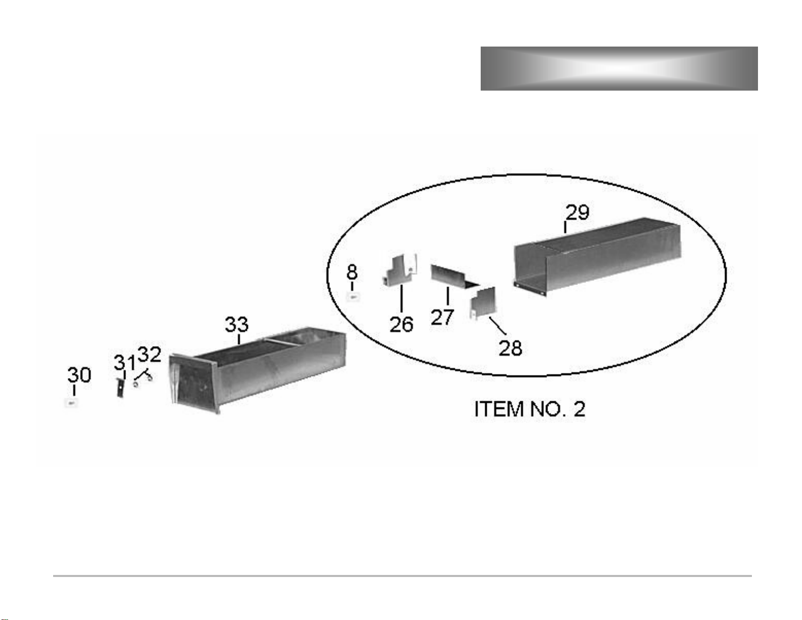
2 Grease Drawer Slide Assembly See Page 17 1
3 Control Box See Page 16 1
4 Griddle Body N/A 1
5 Access Panel LGCL-422 1
6 Leg, 4” with Round Adjustable Toe 72500-12 4
7 Supply Wire Baffle LGCL-227 1
8 Screw Stainless Steel 10-32 x 1/2” Hex Head Cap 20111-09 19
9 Rear Cover LGCL-507 1
10 Ground Wire 24” LGCL-770 4
11 Wire Harness LGCL-585 1
12 Terminal Block 2 Pole, Large 175 Amp 30500-11 2
13
14
15 Element Box LGCL-725
16 Snap Bushing 1 3/8” SB1375-16 Black 70801-02 2
Thermostat, Griddle, 550°F
Knob, Thermostat, 550°F
30402-07 3
70701-19 3
17 Electric Box Cover LGCL-524 1
18 Element, Griddle 440 Volt 5991 Watts 11030-48 3
19 Nut, Hex, Stainless Steel, 10-32 20303-02 6
20 Element Pan, Zig-Zag LGCL-439 3
21 Element Pan, Insulation XL-424 3
22 Element Pan LGCL- 434 3
23 Washer, Stainless Steel, Flat 20203-05 18
24 Nut, Hex, Stainless Steel, 5/16-18 20303-07 18
25 Thermostat Holder LGCL-504 3
26 Grease Snout Guard, Left Hand LGCL-100-1 1
27 Grease Snout Guard, Rear LGCL-100-2 1
28 Grease Snout Guard, Right Hand LGCL-100 1
29 Grease Drawer Slide LGCL-228 1
30 Screw, Stainless Steel, 1/4-20 x 5/8 Hex Head Cap 20111-03 2
31 Grease Drawer Stop LGCL-234-1 1
32 Nut, Hex Stainless Steel, 1/4-20 20303-01 4
33 Grease Drawer LGCL-235 1
13
Page 14

EXPLODED VIEW
14
Page 15

EXPLODED VIEW CONT’D
15
Page 16

EXPLODED VIEW CONT’D
16
Page 17
EXPLODED VIEW CONT’D
17
Page 18

WIRING DIAGRAM
18
Page 19

Lang Manufacturing Limited Warranty
to Cruise Line Purchasers
WARRANTY
Lang Manufacturing Equipment (“Lang
Equipment”) has been skillfully manufactured,
carefully inspected and packaged to meet rigid
standards of excellence. Lang warrants its
Equipment to be free from defects in material and
material-related workmanship for (13) thirteen
consecutive months from the date of initial
shipboard installation or (18) eighteen consecutive
months from date of initial factory shipment, which
ever comes first. The aforementioned warranty
statement is subject to the following conditions and
limitations.
I. This warranty is limited to the provision of
replacement components for Product sold by Lang to
a joiner company for installation aboard a cruise
ship, or a cruise ship company for installation aboard
its own ship. The provision of replacement
components to affect Product repairs will be on a nocharge basis during the term of the warranty.
Replacement components will be sent to the address
required within 48 hours of Lang receiving written
notification of the description of the defect and the
model and serial number of the Product affected by
the repair.
Quartz elements are warranted for ninety (90) days
from the date of installation.
III. Replacement components will be shipped
F.O.B. factory with freight prepaid.
Replacement component damage related to
shipment is not covered under this warranty.
IV. This warranty does not co ver consumable
parts such as quartz elements, and does not
cover defects caused by improper installation,
abuse, careless operation, or improper
maintenance of Product.
V. All warranties are conditioned upon Lang’s
receipt of written notice of any defect prior to the
end of the applicable warranty period.
VI.
THIS WARRANTY IS EXCLUSIVE AND IS
IN LIEU OF ALL OTHER WARRANTIES,
EXPRESSED OR IMPLIED, INCLUDING ANY
IMPLIED WARRANTY OF
MERCHANTABILITY OR FITNESS FOR A
PARTICULAR PURPOSE, EACH OF WHICH IS
HEREBY EXPRESSLY DISCLAIMED. THE
REMEDIES DESCRIBED ABOVE ARE
EXCLUSIVE AND IN NO EVENT SHALL LANG
BE LIABLE FOR SPECIAL, CONSEQUENTIAL
OR INCIDENTAL DAMAGES FOR THE
BREACH OR DELAY IN PERFORMANCE OF
THIS WARRANTY.
II. Damage during shipment is to be reported to the
carrier, is not covered under this warranty, and is the
sole responsibility of purchaser/user.
VII. Lang Equipment is for cruise line use only. If
sold as a component of another (OEM)
manufacturer’s equipment, or if used as a consumer
product, such Equipment is sold AS IS and without
any wa r ranty.
19
 Loading...