

Page 1
Contact Clamshell
Owner’s Manual
Models
CCSE12
This manual includes material related to installation,
use , cleaning, and care. Exploded view(s), as well
as any available parts list(s) and wiring diagram(s)
pertaining to the unit(s) covered by this manual are
also included.
This manual must be read and understood by all
persons using or installing this appliance. Contact
your Lang dealer if you have any questions concerning
installation, use, or maintenance of this equipment.
DO NOT DISCARD THIS MANUAL.
One [1] CCSE12
contact clamshells
mounted on
a 24-inch
griddle.
2M-W2121 • Rev. Q • 10.2018
Page 2

LIMITED EQUIPMENT WARRANTY
Lang Manufacturing [as well as its subsidiaries] warranties new products
to be free from defects in material and/or workmanship for a period
of one [1] year from the date of original installation, except as noted
below. Defects that occur as a result of normal use, within the time period
and limitations defined in this warranty, will at Lang’s discretion have the
parts replaced or repaired by Lang or a Lang-authorized service agency.
THIS WARRANTY IS SUBJECT TO ALL LISTED CONDITIONS.
Repairs performed under this warranty are to be performed by a Langauthorized service agency. Lang will not be responsible for charges
incurred or service performed by non-authorized repair agencies.
In all cases, the nearest Lang-authorized service agency must be used.
Lang will be responsible for normal labor charges incurred in the repair or
replacement of a warrantied product within 50 miles (80.5 km) of
an authorized service agency. Time and expense charges for anything
beyond that distance will be the responsibility of the owner. All labor
will need to be performed during regular service hours. Any overtime
premium will be charged to the owner. For all shipments outside the
U.S.A. and Canada, please see the International Warranty for specific
details.
It is the responsibility of the owner to inspect and report any shipping
damage claims, hidden or otherwise, promptly following delivery.
No mileage or travel charges will be honored on any equipment that is
deemed portable. In general, equipment with a cord and plug weighing
less than 50 lb. (22.7 kg) is considered portable and should be taken or
shipped to the closest authorized service agency, transportation
prepaid .
CONTACT
Should you require any assistance regarding the operation or
maintenance of any Lang equipment; write, phone, fax or email
our service department. In all correspondence mention the
model number and the serial number of your unit, as well as the
voltage or type of gas you are using.
Business hours are 8:00 a.m. to 4:30 p.m. Central Standard Time
Telephone 314.678.6315
Fax 314.781.2714
Email customerservice@star-mfg.com
www.langworld.com
WARRANTY EXCLUSIONS
THE FOLLOWING WILL NOT BE COVERED UNDER WARRANTY.
• Any product which has not been used, cleaned, maintained,
or installed in accordance with the directions published in the
appropriate installation sheet and/or owner's manual as well
as national and local codes, including incorrect gas, electrical,
or water connection. Lang is not liable for any unit which has been
mishandled, abused, misapplied, subjected to chlorides, harsh
chemicals, or caustic cleaners, damaged from exposure
to hard water, modified by unauthorized personnel, damaged
by flood, fire, or other acts of nature [or God], or which have
an altered or missing serial number.
• Installation, labor, and job checkouts, calibration of heat controls,
air and gas burner/bypass/pilot adjustments, gas or electrical
system checks, voltage and phase conversions, cleaning
of equipment, or seasoning of griddle surface.
• Replacement of fuses or resetting of circuit breakers, safety
controls, or reset buttons.
• Replacement of broken or damaged glass components, quartz
heating elements, and light bulbs.
• Labor charges for all removable parts in gas charbroilers and
hotplates, including but not limited to burners, grates, and radiants.
• Any labor charges incurred by delays, waiting time, or operating
restrictions that hinder a service technician’s ability to perform
service.
• Parts that fail or are damaged due to normal wear or labor for
replacement of Items that can easily be replaced during a daily
cleaning routine. such as but not limited to silicone belts, PTFE
non-stick sheets, knobs, control labels, bulbs, fuses, quartz
heating elements, baskets, racks, and grease drawers.
• Components that should be replaced when damaged or worn,
but have been field-repaired instead [eg. field-welded fry pots]
• Any loss of business or profits.
ADDITIONAL WARRANTIES
Specialty/chain specific versions may also have additional
and/or extended warranties.
PRODUCTS PARTS LABOR
Lang Chef-Series™
convection ovens
Lang Strato-Series™
convection ovens
Lang convection oven doors
[excluding hardware]
2 years 2 years
2 years 2 years
lifetime
2 years
Lang griddles and charbroilers
chrome griddle surfaces [against
original Lang parts sold to repair
The fore going warrant y is in lieu of any and a ll other warranti es expresse d or implied and c onstitutes the e ntire warranty.
peeling]
cast iron grates, burners,
and burner shields
Lang equipment
Service First 1 year
2M-Z22519 • Rev - • 02.2018
2 years 2 years
5 years
180 days
90 days
Page 3

TABLE OF CONTENTS
Warranty
cifications
Spe
General Information and Installation
Control Box Wiring
Daily Operation / Cleaning
Troubleshooting
Wiring Diagram
Parts List
Exploded Views
PTFE Sheet Installation
i
iii
1–2
3
4
5
6
7
8–9
10
2M-W2121 Rev. Q Owner's Manual for CCSE12 Contact Clamshell
Page 4
SPECIFICATIONS
SAFETY SYMBOLS
These symbols are intended to alert the user to the
presence of important operating and maintenance
instructions in the manual accompanying the appliance.
THOROUGHLY INSPECT YOUR UNIT ON ARRIVAL
This unit has been tested for proper operation before leaving our plant to ensure delivery of your unit
in perfect condition. However, there are instances in which the unit may be damaged in transit. In the
event you discover any type of damage to your product upon receipt, you must immediately contact
the transportation company who delivered the item to you and initiate your claim with that company.
If this procedure is not followed, it may affect the warranty status of the unit. If damage or loss is not
apparent until after equipment is unpacked, a request for inspection of concealed damage must be
made with carrier within 15 days. Please record the model number, serial number, voltage, and purchase
date in the area below at the time of receipt..
Model Number
Serial Number
Voltage
Purchase Date
MAINTENANCE AND REPAIRS
Contact your local authorized service agent for service or required maintenance. Please have the
information in the above fields ready when you call to ensure a faster service.
Using any part other than genuine Star factory supplied parts relieves the manufacturer of all liability.
Due to periodic changes in designs, methods, procedures, policies, and regulations, the specifications
contained in this document are subject to change without notice. Star reserves the right to change
product specifications and design without notice. In regards to previously purchased equipment,
such revisions do not entitle the buyer to corresponding changes, improvements, additions or
replacements. While Star International Holdings Inc. exercises good faith efforts to provide information
that is accurate, we are not responsible for errors or omissions in information provided or conclusions
reached as a result of using the specifications. By using the information provided, the user assumes
all risks in connection with such use. When performing maintenance, power to the unit should be
unplugged or turned off.
PLEASE REFER TO THE WARRANTY PAGE FOR SPECIFIC WARRANTY INFORMATION.
AUTHORIZED SERVICE AGENT LISTING
Reference the listing provided with the unit or for an updated listing go to the website or call customer
service to find an agent.
Business hours: 8:00 a.m. to 4:30 p.m. Central Standard Time
Telephone: 314-678-6303
Fax: 314-781-2714
Email: customerservice@star-mfg.com
Website: www.langworld.com
Please visit www.starwebconnect.com/manuals.aspx for digital versions of any documents associated
with this unit.
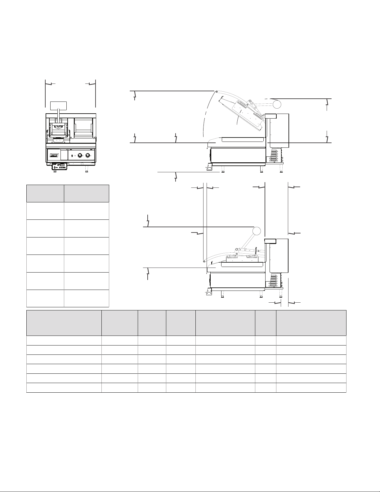
Two [2] CCSE12 mounted on
124THE griddle shown.
24.1 in.
(612 mm)
[no change]
NUMBER
OF HOODS
1
2
3
4
5
6
NUMBER OF
HOODS PER
CONNECTOR BOX
ADDITIONAL
WEIGHT
(36.3 kg)
(70.3 kg)
(106.6 kg)
(140.6 kg)
(176.9 kg)
(210.9 kg)
1 208, 1Φ 20.2 4.2 12 60 6-30P
2 208, 1Φ 40.4 8.4 8 60 6-50P
1 240, 1Φ 17.5 4.2 14 60 6-30P
2 240, 1Φ 35 8.4 8 60 6-50P
1 480, 1Φ 8.8 4.2 14 60 N/A
2 480, 1Φ 17.6 8.4 12 60 N /A
80 lb.
155 lb.
235 lb.
310 lb.
390 lb.
465 lb.
ADDITIONAL INSTALLATION INFORMATION
Dimensions are expected changes when mounted to griddle. For information on griddle
dimensions, refer to the spec sheet for that griddle. A griddle will support one [1] hood
per foot of griddle width. Up to two [2] hoods can use one [1] electrical connector box—
setups with more than two hoods will use additional electrical connector boxes.
24.8 in.
(630 mm)
[typical additional height
from griddle plate]
0.75 in.
(19 mm)
[added to platen height]
(41 mm)
[added to
griddle depth]
19.6 in.
(498 m m)
[typical additional height
from griddle plate]
VOLTAGE,
PHASE
AMPS TOTAL
1.6 in.
KW
MINIMUM SUPPLY
WIRE GAUGE
fully opened dimensions
21.1 in.
(536 mm)
fully closed dimensions
11.1 in.
(282 mm)
[added to
griddle depth]
40.9 in.
(1.04 m)
3.6 in.
(91 mm)
[additional foot
for stability]
HZ RECOMMENDED
NEMA PLUG
[NO PLUG INCLUDED]
iii
Page 5

SAFETY SYMBOLS
These symbols are intended to alert the user to the
presence of important operating and maintenance
instructions in the manual accompanying the appliance.
THOROUGHLY INSPECT YOUR UNIT ON ARRIVAL
This unit has been tested for proper operation before leaving our plant to ensure delivery of your unit
in perfect condition. However, there are instances in which the unit may be damaged in transit. In the
event you discover any type of damage to your product upon receipt, you must immediately contact
the transportation company who delivered the item to you and initiate your claim with that company.
If this procedure is not followed, it may aff ect the warranty status of the unit. If damage or loss is not
apparent until after equipment is unpacked, a request for inspection of concealed damage must be
made with carrier within 15 days. Please record the model number, serial number, voltage, and purchase
date in the area below at the time of receipt..
Model Number
Serial Number
Voltage
Purchase Date
MAINTENANCE AND REPAIRS
Contact your local authorized service agent for service or required maintenance. Please have the
information in the above fi elds ready when you call to ensure a faster service.
Using any part other than genuine Star factory supplied parts relieves the manufacturer of all liability.
Due to periodic changes in designs, methods, procedures, policies, and regulations, the specifi cations
contained in this document are subject to change without notice. Star reserves the right to change
product specifi cations and design without notice. In regards to previously purchased equipment,
such revisions do not entitle the buyer to corresponding changes, improvements, additions or
replacements. While Star International Holdings Inc. exercises good faith eff orts to provide information
that is accurate, we are not responsible for errors or omissions in information provided or conclusions
reached as a result of using the specifi cations. By using the information provided, the user assumes
all risks in connection with such use. When performing maintenance, power to the unit should be
unplugged or turned off .
PLEASE REFER TO THE WARRANTY PAGE FOR SPECIFIC WARRANTY INFORMATION.
AUTHORIZED SERVICE AGENT LISTING
Reference the listing provided with the unit or for an updated listing go to the website or call customer
service to fi nd an agent.
Business hours: 8:00 a.m. to 4:30 p.m. Central Standard Time
Telephone: 314-678-6303
Fax: 314-781-2714
Email: customerservice@star-mfg.com
Website: www.langworld.com
Please visit www.starwebconnect.com/manuals.aspx for digital versions of any documents associated
with this unit.
1
2M-W2121 Rev. Q Owner's Manual for CCSE12 Contact Clamshell
Page 6

THE NAMEPLATE IS LOCATED BEHIND THE CLAMSHELL BETWEEN THE TWO PIVOT ARMS.
THE CLAMSHELL VOLTAGES, WATTAGE, SERIAL NUMBER, WIRE SIZE, AND CLEARANCE
SPECIFICATIONS ARE ON THE DATA PLATE. CAREFULLY READ AND UNDERSTAND THIS
INFORMATION BEFORE PROCEEDING WITH THE INSTALLATION.
GENERAL SAFETY INFORMATION
This equipment is designed and sold for commercial use only, and is intended for use by personnel
trained and experienced in its operation. This is not sold for consumer use in and around the home
nor for use directly by the general public in food service locations.
Before using your new equipment, read and understand all the instructions and labels associated
with the unit prior to putting it into operation. The presence of safety equipment and components
cannot, in and of themselves, assure absolute safety of operation. Diligent, capable, well-trained
operators and maintenance personnel, as well as proper programs of operation and maintenance,
are essential to the safe and reliable operation of this unit.
Lang manufacturing is not responsible for injury, damage, loss or other claim that may occur to person
or property from improper alteration, modification, addition, operation, maintenance or service, whether
it be mechanical, electrical, or otherwise, which may occur from such improper alteration, modification,
addition, operation, maintenance or service to this piece of equipment.
GENERAL INSTALLATION INFORMATION
The unit is shipped fully assembled. It will be shipped in a crate, and on a skid. The unit as a whole is very
heavy and should be moved carefully to avoid damage or injury. Make certain any counter or stand the
unit is being installed upon is rated to hold the total weight of the unit. Do not remove the crating until
the unit is as close as possible to the final install location. When removing crating, be careful of cutting
shipping straps as they are under tension and can snap back when cut.
Make certain to observe the minimal clearances recorded on the nameplate of the unit when installing.
If operated improperly, damage to persons or property may result. Installation of extractor or suppression
systems must conform to applicable national, state, and locally recognized installation standards.
Before using the unit for the first time, ensure to clean and season the griddle and clean the clamshell
properly.
ELECTRICAL CONNECTION
Electrical installation must only be performed by a certified electrical technician. The clamshell comes
in a 208 V, 240 V, or 480 V version, which must be specified at the time of ordering. The units
are shipped being set up for 3-phase, but can be converted to single phase in the field. Before making
any electrical connection to this unit, check that the power supply is adequate for the voltage, amperage,
and requirements stated on the rating plate. Start by ensuring the griddle has been correctly installed.
Do not connect equipment to power without proper ground connections. Improper grounding may
result in personal injury or fatality. Proceed to connecting electrical service to the box[es].
Make certain to disconnect the unit from the power source before installing or removing any parts.
BLK
RED
L3 L2 L1
WHT
GRN
BLK
WHT
2
Page 7

CONTROL BOX WIRING
1. Run the control box wiring through the tray.
The end of the control box wire with the circular
connector should extend from the rear side.
2. Loosen the two bolts under the griddle on the
stabilizer that line up with the slots in the tray.
Slide the tray into place and tighten bolts.
3A. Remove the bolt [1 of 2]
holding the connection box
to the stabilizer.
3B. Remove the bolt [2 of 2]
holding the connection box
to the stabilizer.
4. Slide the connection box back until the
wiring block can be accessed. Connect wiring
and reinstall box.
3
2M-W2121 Rev. Q Owner's Manual for CCSE12 Contact Clamshell
Page 8

LOCKOUT PROCEDURE
USE THIS PROCEDURE WHEN PERFORMING ANY
SERVICE OR REPAIR TO ENSURE THE SAFETY OF
ALL PERSONNEL ON SITE.
i. Announce the lockout to other personnel.
ii. Turn the power o at the main panel.
iii. Test lockout by turning power switch on and
observing if the elements come on.
iv. Check the heater circuit with a voltmeter.
v. Perform necessary repairs or tests.
vi. Clear the unit of personnel before starting
the griddle.
vii. Turn power on at main panel
viii. Announce unit is “on” to other personnel.
OPERATION
CERTAIN SURFACES ARE EXTREMELY HOT DURING
OPERATION AND CARE SHOULD BE TAKEN WHILE
USING THIS UNIT.
DO NOT LEAVE THE UNIT IN OPERATION WITHOUT
AN ATTENDANT.
DO NOT LEAVE THE UNIT AT HIGH TEMPERATURE
WHEN NOT IN USE OR DURING IDLE PERIODS.
ALWAYS KEEP THE AREA NEAR THE APPLIANCE
FREE FROM COMBUSTIBLE MATERIALS.
KEEP FLOOR IN FRONT OF EQUIPMENT CLEAN
AND DRY. IF A SPILL OCCURS, CLEAN IMMEDIATELY
TO AVOID THE DANGER OF SLIPS OR FALLS.
INITIAL START UP
Each unit is tested and calibrated at the factory prior
to shipment. Due to temperature and climate changes
during shipment the unit can absorb moisture. Check
for moisture and allow the unit to dry before placing
the unit into full operation. Prior to putting any unit
into full-time operation at normal cooking temperatures,
it must be thoroughly dried out. Moisture absorption
in closed spaces— like the insulation and even inside
the heating elements—can cause future trouble if not
properly treated. Make certain to pre-heat the griddle
for one hour, if the unit has been out of service for three
days or more, especially when exposed to high humidity
and/or cool temperatures.
During the first few hours of operation, you may notice
a small amount of smoke and a faint odor from the
smoke. This is normal for a new unit and will disappear
after the first few hours of use.
DA ILY USE
The unit should be allowed to preheat for approximately
30 minutes in the up position prior to use. After this period,
the unit will be ready for use until powered down.
LEVELING ADJUSTMENT
The adjusting knob, centered above the clamshell body,
can be turned clockwise to raise the back and lower the
front of the unit and counterclockwise to raise the front
and lower the back of the unit.
CLEANING
Refer to your griddle’s manual for maintenance and
cleaning information regarding the griddle itself.
The clamshell hood should be wiped down daily with
cleaner to remove any excess grease or residue on the
exterior surfaces. DO NOT SUBMERGE THE UNIT OR
ALLOW FLUID TO PENETRATE THE REAR HOUSING.
If fluid is allowed to enter the rear housing, it will clean
away the permanent lubricant neccesary for quiet,
smooth operation of the clamshell. Do not allow excess
moisture to come in contact with the control for the
clamshell, mounted on the lower front of the griddle.
Once a week, with a cold griddle, lower the clamshell
hood and allow to heat for 30 minutes [or more if
necessary] to burn o excess carbon and baked-on
grease.
ADJUSTING TIME AND TEMPERATURE
EACH CLAMSHELL WILL HAVE ITS OWN INDEPENDENT
CONTROL BOX.
i. Press and hold “TEMP” [actual temperature displays].
ii. While holding “TEMP” press and hold any program
button on the for three seconds. The LED above the
program number will light and the display will read
“_ _ _ _”. Enter the four-digit security code sequence
4, 3, 2, 1. Once the sequence has been successfully
entered, the preset time will be displayed and the
LED for that program will begin to flash.
iii. Set the desired time with the “3/+” to increase time
or “4/-” to decrease time. Press the “TEMP” button
to save changes.
iv. The temperature setting will now be displayed and
can be programmed. Set the desired temperature
with the “3/+” to increase the temperature or “4/-”
to decrease temperature. Press the “TEMP” button
again to save changes.
v. Press any other program button within 15 seconds
to continue programming without re-entering the
security code.
4
Page 9

TROUBLESHOOTING
ERROR CODES
The con
diagnosis is still required as these codes are meant to show how or where a malfunction has been
detected, not necessarily what is causing the malfunction.
i. PRO1—If the control board detects that the temperature probe has an open or shorted circuit,
ii. RELY— If the unit is powered on and either remains below 150° F (66° C) for 30 minutes, or exceeds
trol can display codes based on perceived faults in the system. It should be noted, proper
this error code will display on the screen. Whenever this code is displayed, power will
be cut to the relay.
640° F (338° C), this error code will display on the screen. Whenever this code is displayed,
power will be cut to the relay.
CALIBRATION CHECK
BE EXTREMEL
Y CAREFUL WHEN WORKING ON THE UNIT WHEN IT IS WARM.
DIRECT CONTACT WITH THE COOKING SURFACE CAN RESULT IN SEVERE BURNS.
SUGGESTED EQUIPMENT
i. K-type thermocouple thermometer with a surface probe, rated to at least 500° F (260° C).
CLAMSHELL
The clamshell should be set at 350° F (177° C) to ensure accuracy. Refer to the owner’s manual
for instructions on how to set temperature.
i. Allow the unit to remain in the up position, with the power on, for 30 minutes.
ii. Place the thermocouple probe 15.75 in. (40 cm) from the front of the platen surface, centered
from left to right.
iii. If the temperature is set as directed above, the probe should read ±15° F (8° C) from the set
temperature.
iv. If the test does not fall within the given parameter, the temperature oset in the control
programming may be adjusted to compensate by authorized personnel or technician.
TEMPERATURE OFFSET ADJUSTMENT
A. To adjust the the temperature oset, press and hold the “TEMP” button and switches
“3” and “4” for 2–4 seconds. Release the buttons as soon as the oset value is displayed.
B. Increase the oset by pressing switch “3” or decrease the oset by pressing switch “4”
in order to adjust for the dierence in desired and observed temperatures. Increases and
decreases shall be in 1° F or 1° C increments depending on the unit’s current settings.
C. Once the desired oset is displayed, press the “TEMP” switch.
D. The current TCTD setting will be displayed. This value should not be adjusted during this
process. Press the “TEMP” switch to exit programming.
E. Perform step i–iii [above] again to confirm the change has had the desired result. If not,
repeat steps A–E.
5
2M-W2121 Rev. Q Owner's Manual for CCSE12 Contact Clamshell
Page 10

WIRING DIAGRAM
6
Page 11
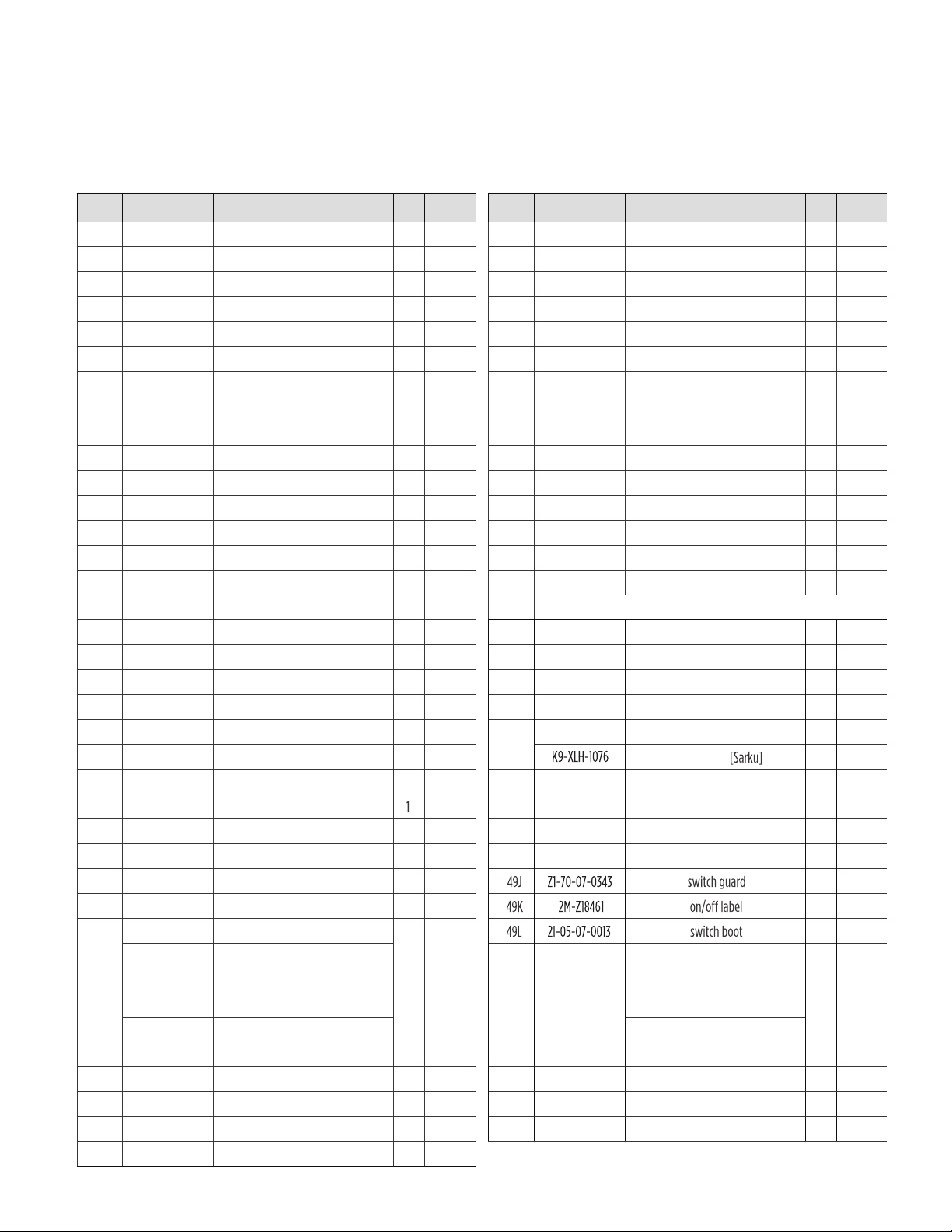
PARTS LIST
Side references are from the operator's point-of-view—from the front of the unit. Items labeled “NS”
are non-serviceable. Items labeled “NP” are not pictured. All quantities are per single clamshell hood
or per electrical connection in the case of parts 50, 51, 53, and 54. Other parts, such as a mounting frame,
will need to be purchased with the griddle and clamshell also.
REF NO PART NUMBER DESCRIPTION QTY PAGE NO
1 2V-XLH-901 counterweight 1
2 2V-XLH-890 rear leveling link bracket 1
3 2A-XLH-889 rear leveling link pivot shaft 1
4 2V-XLH-1010 rear section, leveling link 1
5 2F-XLH-1011 center section, leveling link 1
6 2V-XLH-1009 front section, leveling link 1
7 2V-XLH-917 upper leveling block base 2
8 2V-XLH-916 lower leveling block base 2
9 K9-XLH-1025 non-stick sheet clip 5
10 2V-XLH-866 leveling hinge block 2
11 2M-60301-W2 clamshell logo 1
12 2C-20111-09 #10-32 x 0.5-inch screw 8
13 2C-20602-04 tinnerman nut 2
14 K9-XLH-1023 conduit mounting bracket 1
15 K9-XLH-1022 conduit end seat 1
16 2C-20201-07 0.25-inch ID flat washer 14
17 2C-20202-05 0.25-inch ID split lock washer 10
18 2C-20111-03 1/4-20 x 0.625-inch screw 8
19 2C-20102-12 #10-32 x 0.375-inch screw 24
20 2C-302520 5/16-18 acorn nut 6
21 2C-20201-06 5/16 ID flat washer 18
22
2T-30401-35
fixed thermostat 1
23 2C-20102-08 8-32 x 0.375-inch screw
24 K9-XLH-929 bracket
25 K9-XLH-928 element hold-down bracket 1
26 K9-XLH-1035 element pan cover 1
27 K9-XLH-1037 element plate 1
28 K9-XLH-826 insulation 1
8
8
8
8
8
8
8
8
8
8
8
8
8
8
8
8
8
8
8, 9
8
8
8
4 8
8
8
8
8
8
2N-11060-35 208 V inner element
29 2N-11060-39 240 V inner element 1
8
2N-11060-41 480 V inner element
2N-11060-34 208 V outer element
1
30 2N-11060-38
240 V outer element
8
2N-11060-40 480 V outer element
31 2C-20301-13 1/4-20 nut 14
32 2V-XLH-866 hinge block 1
33 2E-Z20781 RTD probe 1
34 K9-XLH-920 weld plate 1
8
8
8
8
REF NO PART NUMBER DESCRIPTION QTY PAGE NO
35 2C-20106-14 shoulder screw 2
36 2A-XLH-854 handle 1
37 2C-20105-22 3/8-16 x 3-inch set screw 4
38 2A-5401 0.09735-inch x 0.75-inch cotter pin 2
39 2V-XLH-893 spring shaft key 2
40 K9-XLH-875 right outside pivot bracket 1
41 K9-XLH-853 right arm 1
42 2K-XLH-915 aluminum bushing 2
43 2P-51001-42 spring, right 1
44 2A-XLH-876 shaft collar 1
45 2P-51001-43 spring, left 1
46 2V-XLH-888 spring shaft 1
47 K9-XLH-852 left arm 1
48 K9-XLH-874 left outside pivot bracket 1
49 K9-XLH-959 control box 1
9
9
9
9
9
9
9
9
9
9
9
9
9
9
9
THE BELOW PARTS [49A–49L] ARE PART OF THIS ASSEMBLY [49]
49A K9-XLH-962 control box front 1
49B 2E-Z12020 toggle switch 1
49C 2M-60301-187 control box overlay 1
49D 2A-20504-12 nylon spacer 4
49E
2J-Z17605
control board 1
control board
49F 2C-20301-11 #8-32 nut 4
49G K9-XLH-964 control box rear 1
49H K9-XLH-961 control box top 1
49I K9-XLH-960 control box bottom 1
9
9
9
9
9
1
9
9
9
9
9
NP
1
NP
1
NP
1
50 2E-30900-30 60 amp fuse 2 NP
51
52 1 NP
2E-30901-15 fuse block 1
2E-30600-15 208 V/240 V relay
2E-30600-16
480 V relay
53 2E-31200-02 lug ground 1
NP
NP
54 2E-Z15018 transformer 1 NP
54
55
K9-XLH-734 conduit assembly
K9-XLH-1132 bracket, high limit mount
1 NP
1 8
7
2M-W2121 Rev. Q Owner's Manual for CCSE12 Contact Clamshell
Page 12

MAIN BODY
1
2
3
4
5
6
7
9
8
15
14
16
17
18
19
55
22
23
Models After 10/2018
11
10
12
C
13
20
21
26
31
31
B
24
21
21
27
25
19
12
28
29
30
31
17
16
32
33
A
34
8
Page 13

HANDLE/ARMS
and CONTROLLER
35
36
35
38
39
40
41
42
43
44
37
45
42
46
47
48
39
49L
49K
49J
49B
49A
49C
49I
49D
49E
49F
49H
49G
19
9
2M-W2121 Rev. Q Owner's Manual for CCSE12 Contact Clamshell
Page 14

CCSE12 Contact Clamshell
PTFE Non-Stick Sheet Kit CCSE12C-10NS
PTFE Non-Stick Sheet Installation
BE CAREFUL DURING INSTALLATION. IF THE GRIDDLE AND/OR CLAMSHELL HAVE BEEN
IN OPERATION, THEY AS WELL AS THE MOUNTING CLIPS FOR THE PTFE WILL BE VERY
HOT AND SHOULD BE HANDLED/TOUCHED WITH CAUTION AND PROPER PROTECTION.
i. Insert the rod into the eyelet that runs through the rear of sheet.
ii. Line the rod up and set the ends into the two rear channels [one on each side].
iii. Tuck the back of the PTFE sheet up against the back splashguard and along griddle surface,
making a soft 90 degree fold where the two meet.
iv. Gently lower the clamshell onto the PTFE sheet making certain the flaps on both sides and
front are clear of the clamshell.
v. Fold the front flap up and around the top of the front tab and place a clamp over the top to
hold it in place. [labeled CF]
vi. Repeat the same process on the right and left, which will have two clips each. [labeled CS]
vii. Raise the clamshell and check to make sure PTFE is flush running the length of the clamshell.
There should still be a small amount of slack to allow for slight movement when raising and
lowering the clamshell.
Installation Instructions
CS
CF
PTFE NON-STICK SHEET
[all clips are identical, positions are simply labeled
dierently to relate to specific steps]
CS
CS
CS
CLIP
10
Page 15

NOTES
11
Page 16

LANG MANUFACTURING
•
www.langworld.com
265 Hobson St. • Smithville, Tennessee 37166
Telephone 314 678 6315 • Fax 314 781 3636
Printed in the U.S.A. • 2M-W2121 • Rev. Q • 10.2018
Specifications are subject to change without notice.
 Loading...