

Page 1
Laney
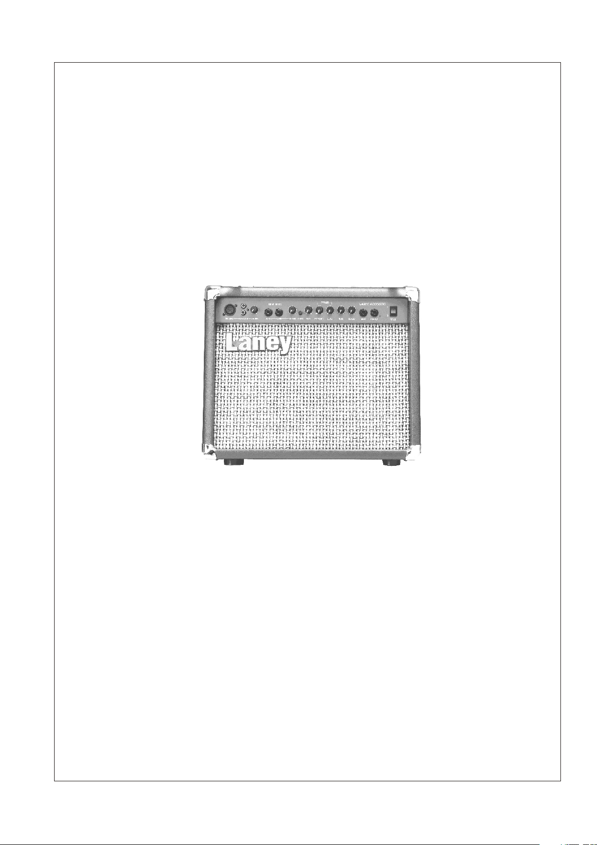
LA30, LA30C & LA60C
USER MANUAL
Page 2

Laney
INTRODUCTION
Congratulations on your decision to purchase a Laney amplifier.
Laney products are designed with ease of operation as a primary objective, however to ensure you derive the best
from your new amplifier, it is important you take time to read this user manual and to familiarise yourself with the
control functions and facilities available.
BEFORE
SWITCHING ON
After unpacking your amplifier check that it is factory fitted with a three pin 'grounded' (or earthed) plug.
Before plugging into the power supply ensure you are connecting to a grounded earth outlet.
If you should wish to change the factory fitted plug yourself, ensure that the wiring convention applicable to
the country where the amplifier is to be used is strictly conformed to. As an example in the United Kingdom
the cable colour code for connections are as follows;
EARTH OR GROUND - GREEN/YELLOW
NEUTRAL - BLUE
LIVE - BROWN
11
This manual has been written for easy access of information. The front and rear panels of each unit are
graphically illustrated, with each control and feature numbered. For a description of the function of each
control feature, simply check the number with the explanations adjacent to each panel.
Your Laney dedicated ACOUSTIC amplifier has undergone a thorough two stage, pre-delivery inspection,
involving actual play testing, as well as burn in.
When you first receive your Laney dedicated ACOUSTIC amplifier, follow these simple procedures:
(I) Ensure that the amplifier is set at the correct voltage for the country it is to be used in.
(ii) Connect your instrument with a high quality shielded instrument cable. Use of cheap cables will
compromise the sound of your instrument and your amplifier.
If there is a problem with your Laney amplifier
DON'T
DO
PHONE YOUR DEALER!
Care of your Laney amplifier will prolong it's life.....and yours!.
ACOUSTIC
Page 3

Laney
LA30C front panel
MIC INPUT
TAPE /
CD IN
654
3
2
1
10
0
VOLUME
GUITAR INPUTS
7
8
9
ACTIVE
PASSIVE
2
3
1
VOLUME
22
PARAMID
500
-0+
1
2
3
4
5
1K
LEVEL
-0+
1
1
1
3
2
2
2
3
3
3
2
4
4
4
5
TREBLE
1
5
5
CHORUS
-0+
1
1
2
2
3
33
4
4
5
5
100
FREQUENCY
BASS
654
7
8
9
0
10
0
REVERB
654
10
LA30C ACOUSTICLA30C ACOUSTIC
7
8
9
INSERT
LINE OUT
1
0
POWER
1
2 3
4
6
5
7 8
9
10 11
12
13
* Front panel diagrams show LA30C front panel. LA30 features are identical apart from Reverb & Chorus
1. Mic Input:
The input socket has been designed to accept both balanced and unbalanced signals from
microphones with an XLR input connector. Good quality low impedance condensor or
dynamic mics should preferably be used for best results, these will ensure the best possible
results from hand-held instruments or closely mic'd instruments.
2. Tape/CD input:
3. Volume:
4. Guitar Inputs:
Phono (RCA) sockets are provided for the connection of tape/CD machines.
Controls the overall listening level of the mic and the tape/CD auxiliary inputs.
Active and Passive/Active inputs are provided for connection of guitars. Guitars with active
circuitry should be connected via the Active socket. Non-active guitars should be connected
using the Passive input. Incidentally, guitars with active circuitry could be placed in the
Active input if pre-amp overloading is desired.
5. Volume:
6. Chorus:
7. Bass:
8. Paramid Frequency:
Controls the overall listening volume of the guitar inputs.
Enables the onboard chorus.
Controls the low frequency response of the pre-amplifier.
Selects the frequency at which the cut or boost selected by the paramid level control (9)
acts; to access LO mid frequencies turn the frequency control anti-clockwise, to access HI
mid frequencies turn the frequency control clockwise.
9. Paramid-Level:
10. Treble:
11. Reverb:
12. Insert:
13. Line Out:
LA30C rear panel
14. Fuse Holder:
Sets the level of boost or cut applied to the frequency set by control 8: for frequency boost,
turn the control clockwise; for frequency cut, turn the frequency control anti-clockwise.
Controls the high frequency response of the amplifier.
Controls the level of reverb on the channel.
Socket provided for accepting the signal from another amplifier, see 13
Socket provided for sending signal to another amplifier or mixing desk. Connecting an LA30C
to another non chorus amp, such as an LA30 via the Line out socket to an insert sock will
produce a dramatic stereo chorus effect between the two amplifier.
CAUTION
REPLACE ONLY WITH
SAME TYPE AND RATING
WARNING
THIS APPARATUS
MUST BE EARTHED
POWER FUSE
T250mA T500 mA
SUPPLY VOLTAGE
~230V ~115V
MAXIMUM POWER
CONSUMPTION
50 WATTS ~50-60Hz
SERIAL No.
MODEL No.HC25
CAUTION
TO REDUCE THE RISK OF
ELECTRIC
SHOCK DO NOT REMOVE
WARNING
TO REDUCE THE RISK
OF FIRE
OR ELECTRIC SHOCK
MADE IN THE U.K. BY BLT INDUSTRIES LTD.
14
Power fuse. This fuse protects the AC power of the overall amplifier. Use only the correct
size and rating
ACOUSTIC
Page 4

Laney
LA60C front panel
3
5
4 6
3
2
1
0
MIC INPUT TAPE/CD IN POWERPASSIVEVOLUME VOLUME PHASE RATE DEPTH BASS
1
2 3
1. Mic Input:
GUITAR INPUTS
7
8
9
10
ACTIVE
4
The input socket has been designed to accept both balanced and unbalanced signals from
2
3
1
4 6
0
5
5
7
8
9
10
CHORUS
5
4 6
3
2
1
9
10
0
16
6
microphones with an XLR input connector. Good quality low impedance condensor or
dynamic mics should preferably be used for best results, these will ensure the best possible
results from hand-held instruments or closely mic'd instruments.
2. Tape/CD input:
3. Volume:
4. Guitar Inputs:
Phono (RCA) sockets are provided for the connection of tape/CD machines.
Controls the overall listening level of the mic and the tape/CD auxiliary inputs.
Active and Passive/Active inputs are provided for connection of guitars. Guitars with active
circuitry should be connected via the Active socket. Non-active guitars should be connected
using the Passive input. Incidentally, guitars with active circuitry could be placed in the
Active input if pre-amp overloading is desired.
5. Volume:
6. Chorus:
Controls the overall listening volume of the guitar inputs.
Enables the onboard chorus.
5
4 6
3
7
8
2
1
0
-
1 1
2
7
8
3
4
9
10
5
7 8
1715
PARAMID
500
+0
2
3
4
5
1 1
2
3
4
1K
100
5
-
-
LEVEL TREBLE REVERB INSERTFREQUENCY
9
+0
+0
1 1
2
2
2
3
3
3
4
4
4
5
5
5
10
LA60C ACOUSTIC
5
4 6
3
7
8
2
1
9
10
0
11
12
1
0
LINE OUT
13
7. Bass:
8. Paramid Frequency:
9. Paramid-Level:
10. Treble:
11. Reverb:
12. Insert:
13. Line Out:
LA30/C/LA60C rear panel
Controls the low frequency response of the pre-amplifier.
Selects the frequency at which the cut or boost selected by the paramid level control (9)
acts; to access LO mid frequencies turn the frequency control anti-clockwise, to access HI
mid frequencies turn the frequency control clockwise.
Sets the level of boost or cut applied to the frequency set by control 8: for frequency boost,
turn the control clockwise; for frequency cut, turn the frequency control anti-clockwise.
Controls the high frequency response of the amplifier.
Controls the level of reverb on the channel.
Socket provided for accepting the signal from another amplifier, see 13
Socket provided for sending signal to another amplifier or mixing desk. Connecting an LA30C
to another non chorus amp, such as an LA30 via the Line out socket to an insert sock will
produce a dramatic stereo chorus effect between the two amplifier.
CAUTION
REPLACE ONLY WITH
SAME TYPE AND RATING
WARNING
THIS APPARATUS
MUST BE EARTHED
POWER FUSE
T250mA T500 mA
SUPPLY VOLTAGE
~230V ~115V
MAXIMUM POWER
CONSUMPTION
50 WATTS ~50-60Hz
SERIAL No.
MODEL No.HC25
CAUTION
TO REDUCE THE RISK OF
ELECTRIC
SHOCK DO NOT REMOVE
WARNING
TO REDUCE THE RISK
OF FIRE
OR ELECTRIC SHOCK
MADE IN THE U.K. BY BLT INDUSTRIES LTD.
14. Fuse Holder:
14
Power fuse. This fuse protects the AC power of the overall amplifier. Use only the correct
size and rating
ACOUSTIC
Page 5

Laney
LA60C front panel
4
5
4 6
3
2
1
0
MIC INPUT TAPE/CD IN POWERPASSIVEVOLUME VOLUME PHASE RATE DEPTH BASS
1
2 3
14. Phase Switch:
GUITAR INPUTS
7
8
9
10
ACTIVE
4
Phase switch assists in the cancellation of low frequency oscillation which are associated
2
3
1
4 6
0
5
5
7
8
9
10
CHORUS
4 6
3
2
1
0
16
6
with acoustic guitar feedback.
15. Chorus Rate:
Allows the rate of chorus sweep to be selected. Should be used in conjunction with 16 in
order to achieve the desired chorus effect.
16. Chorus Depth:
Determines the depth of the chorus sweep to be selected. Should be used in conjunction
with 15 in order to achieve the desired chorus effect.
5
5
4 6
3
7
8
2
1
9
10
0
-
1 1
2
7
8
3
4
9
10
5
PARAMID
500
+0
2
3
4
5
1 1
2
3
4
1K
100
5
-
-
+0
+0
1 1
2
2
2
3
3
3
4
4
4
5
5
5
LEVEL TREBLE REVERB INSERTFREQUENCY
7 8
1715
10
9
LA60C ACOUSTIC
5
4 6
3
7
8
2
1
9
10
0
11
12
1
0
LINE OUT
13
ACOUSTIC
Page 6

1.
BLT Industries LTD.,
Newlyn Road
Cradley Heath
West Midlands
B64 6BE
Tel: (00 44) (0)1384 633821
Fax: (00 44) (0)1384 639186
Web Site http:/www.laney.co.uk
In the interest of continuing product development BLT Industries reserves the right to change specification without prior notice.
 Loading...