

Page 1

EtherTel
10/100Base-T/ E1 Converter TM-78
Operating Manual
IOA78-1C
January 2005
LANEX S.A., 8 Ceramiczna Street, 20-150 Lublin POLAND service phone no.
+48 81 443 96 39
Page 2

10Base-T/100Base-TX/E1 Converter
Table of Contents
1. GENERAL DESCRIPTION ......................................................................................... 1
1.1. Designed use .............................................................................................................................. 1
1.2. Sample applications ..................................................................................................................2
1.3. Integration with other manufacturers’ equipment................................................................ 3
1.4. Labeling ..................................................................................................................................... 3
2. CONNECTORS AND LED INDICATORS ..................................................................... 4
2.1. Front panel ................................................................................................................................ 4
2.2. Rear panel..................................................................................................................................5
2.3. Description of connectors......................................................................................................... 6
3. FUNCTIONAL DESCRIPTION..................................................................................... 7
3.1. Rule of operation....................................................................................................................... 7
3.2. Clock .......................................................................................................................................... 7
3.3. Diagnostic and signaling systems............................................................................................. 7
3.4. Test loops ................................................................................................................................... 8
3.5. Quality management...............................................................................................................10
3.6. Event log .................................................................................................................................. 11
3.7. Service channels ...................................................................................................................... 11
4. INSTALLATION & OPERATION ............................................................................... 12
4.1. Introduction.............................................................................................................................12
4.2. Working conditions.................................................................................................................12
4.3. Power Supply ..........................................................................................................................12
4.4. Connecting connection cables ................................................................................................ 13
4.4.1. Ethernet interface ................................................................................................................. 13
4.4.2. E1/G.703 line interface ........................................................................................................ 13
4.5. Attachment of surveillance cables ......................................................................................... 14
4.6. Clock setup .............................................................................................................................. 15
4.7. Configuration of the E1 G.703 interface............................................................................... 15
Operating Manual
5. CONVERTER SETUP WITH LANWIN SOFTWARE ...................................................... 16
5.1. Global setup............................................................................................................................. 16
5.1.1. Device Name........................................................................................................................ 17
5.1.2. Date and time setting............................................................................................................ 17
5.1.3. Additional information......................................................................................................... 17
5.2. Interfaces .................................................................................................................................18
5.2.1. E1, Setup tab ........................................................................................................................ 18
5.3. Global clock............................................................................................................................. 23
5.4. Log............................................................................................................................................ 24
5.4.1. Event log tab ........................................................................................................................ 24
5.4.2. Event log tab, event log filters .............................................................................................25
5.5. G.826 statistics......................................................................................................................... 28
5.5.1. G.826 statistics, Counters tab............................................................................................... 28
6. TECHNICAL SPECIFICATION .................................................................................. 32
6.1. Electrical characteristics ........................................................................................................ 32
6.1.1. Ethernet interface ................................................................................................................. 32
6.1.2. E1/G.703 line interface ........................................................................................................ 32
6.2. Mechanical parameters .......................................................................................................... 32
6.3. Environmental requirements................................................................................................. 33
6.3.1. Operation.............................................................................................................................. 33
6.3.2. Transport.............................................................................................................................. 33
6.3.3. Storage ................................................................................................................................. 33
6.4. Electromagnetic compatibility............................................................................................... 33
6.5. Power Supply ..........................................................................................................................33
7. PRODUCT ELEMENTS AND ACCESSORIES.............................................................. 34
IOA78-1C I January 2005
Page 3

10Base-T/100Base-TX/E1 Converter
Drawings
Figure 1-2: Example application II. ............................................................................... 2
Figure 1-3: Example application III............................................................................... 3
Figure 2-1: Layout and description of the front panel. .................................................. 4
Figure 2-2: Layout and description of the rear panel..................................................... 5
Figure 2-3: RJ-45 surveillance connector ...................................................................... 6
Figure 2-4: E1/G.703. interface connector..................................................................... 6
Figure 2-5: Ethernet MDI interface connector - port 1 and 2. ....................................... 6
Figure 2-6: MDIX Ethernet interface connector - port 2. .............................................. 6
Figure 3-1: Rules of introducing and using the LOOP1 local loop. .............................. 9
Figure 3-2: Rules of introducing and using the LOOP2 remote loop. ........................... 9
Figure 3-3: Device unavailability................................................................................. 11
Figure 4-1: Ethernet interface RJ-45 male connector. ................................................. 13
Figure 4-2: Method of connecting crossed cable. ........................................................ 13
Figure 4-3. E1/G.703. interface RJ-45 male connector. .............................................. 13
Figure 4-4: RS-232 cable with DB-9 RJ-45 pins.................................................... 14
Figure 5-1: Global setup............................................................................................... 16
Figure 5-2: Device Name. ............................................................................................ 17
Figure 5-3: Date and time setting................................................................................. 17
Figure 5-4: Additional information.............................................................................. 17
Figure 5-5: Interfaces - E1, Setup. ............................................................................... 18
Figure 5-6: Interfaces - E1, Loops. .............................................................................. 19
Figure 5-7: Interfaces - E1, Monitoring. ...................................................................... 20
Figure 5-8: Interfaces - Ethernet, Setup. ...................................................................... 21
Figure 5-9: Interfaces - Ethernet, Monitoring. ............................................................. 22
Figure 5-10: Global clock. ........................................................................................... 23
Figure 5-11: Log - Event log........................................................................................ 24
Figure 5-12: Log - Event log filters. ............................................................................ 25
Figure 5-13. Event log filter – Date. ............................................................................ 26
Figure 5-14. Event log filter – UAL/NUAL. ............................................................... 27
Figure 5-15. G.826 statistics – 15-minute counters. .................................................... 29
Figure 5-16. G.826 statistics – 24-hour counters. ........................................................ 29
Figure 5-17. G.826 statistics – Time periods. .............................................................. 30
Figure 5-18. Count initialization time.......................................................................... 30
Figure 5-19. Ranges. .................................................................................................... 30
Figure 5-20. Alarm on thresholds. ............................................................................... 31
Figure 5-21. Alarms hierarchy. .................................................................................... 31
Operating Manual
IOA78-1C II January 2005
Page 4

10Base-T/100Base-TX/E1 Converter
Operating Manual
Abbreviations
AIS Alarm Indication Signal
NUAL Non-urgent Alarm
UAL Urgent Alarm
ES Errored Seconds
ES15 15-minute Errored Seconds Counter ES
ES24 24-hour Errored Seconds Counter ES
HDLC High Level Data Link Control
IEEE Institute of Electrical and Electronics Engineers
ITU-T International Telecommunication Union – Telecommunication
Standardization Sector
LOF Loss Of Frame
LOS Loss Of Signal
MDI Medium Dependent Interface
MII Medium Independent Interface
SES Severely Errored Second
SES15 15-minute Severely Errored Seconds Counter SES
SES24 24-hour Severely Errored Seconds Counter SES
LOF Loss of Frame
IOA78-1C III January 2005
Page 5

10Base-T/100Base-TX/E1 Converter
Operating Manual
Operating Safety
The EtherTel TM-78 converter has been designed and tested in the range of safety and
operation in accordance with the PN-EN-60950 standards. It conforms to Class I safety
requirements.
! The earthing clamp located on the rear wall of the device should be connected
to earth.
! The device is not provided with an integrated tripping system. Such system
should be located outside the device.
The manufacturer shall not be held liable for use of the device contrary to this
operating manual.
The operating manual is a part of supply and is delivered to users together with
the device.
IOA78-1C IV January 2005
Page 6

10Base-T/100Base-TX/E1 converter
Operating Manual
1. GENERAL DESCRIPTION
1.1. Designed use
EtherTel TM-78 is a converter that enables connecting independent segments of local
area networks in Ethernet 10BASE-T and 100BASE-TX standard, using SDH or PDH
telecommunication network, on the basis of framed signal with transmission rate of 2048 kbit/s,
structure specified in guideline G.704, interface according to guideline G.703. Data transmission
rate can be one of n x 64 kbit/s, where n = 1 ÷ 31. Operation in non-framed mode is also possible
at full speed of 2048 kbit/s.
Each Ethernet package has a destination address field, determining the destination for
transmitted data. EtherTel receives the incoming package and verifies its destination address,
then compares the address with source addresses collected from previous frames and decides
whether the frame should be sent to a second port or not. Therefore, network segments can be
isolated and network capacity can be increased. Flow control, compliant with IEEE802.3x,
determines the method of sending the frames in full duplex mode so that to avoid overloading the
converter.
EtherTel converter also transparently transfers Ethernet frames longer than 1522
bytes, belonging to virtual networks according to IEEE 802.1Q standard, or to setting priorities
IEEE 802.1p.
_______________________________________________________________________________
IOA78-1C 1 January 2005
Page 7
10Base-T/100Base-TX/E1 converter
K
A
T
K
A
2
A
T
A
2
l
A
T
2
l
A
T
2
l
A
T
2
l
A
T
2
l
A
2
l
A
2
l
A
2
l
A
2
Operating Manual
1.2. Sample applications
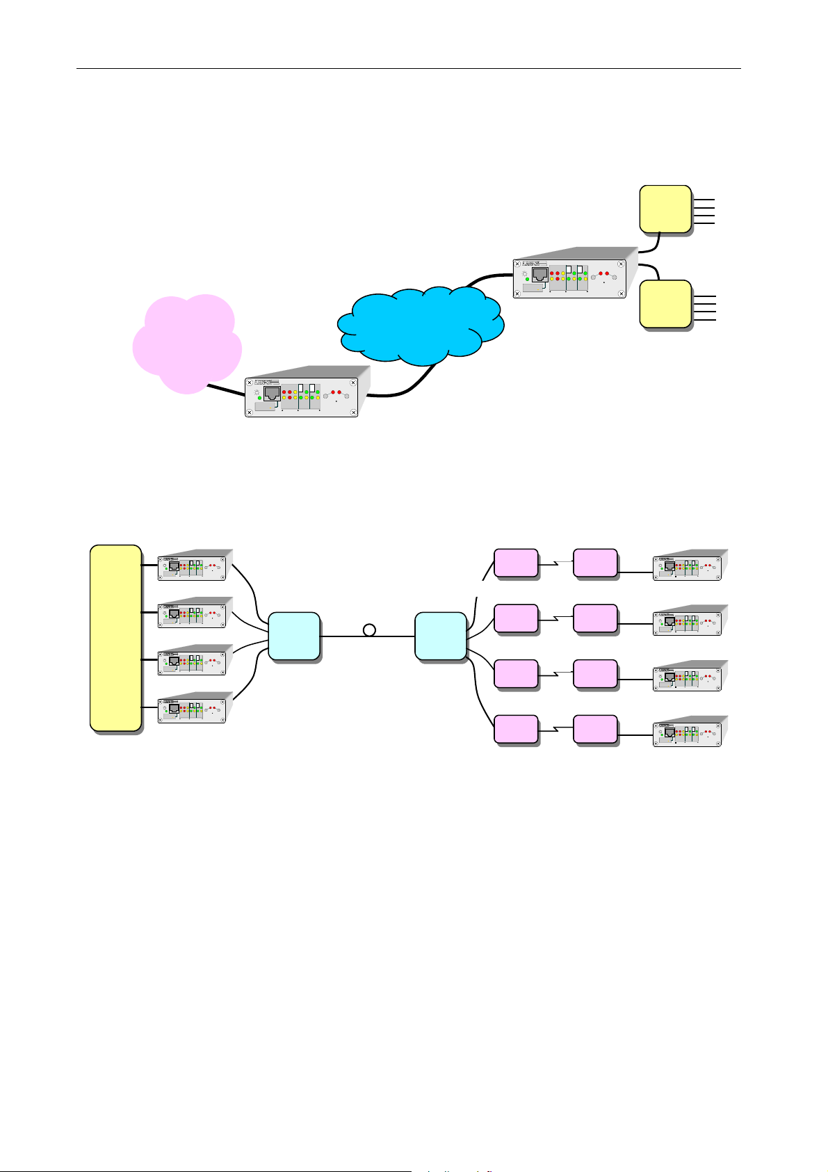
One of the simplest applications is the possibility of providing Internet access service using
telecommunication network with transmission speed gradation n x 64 kbit/s. The service operator
may freely switch the range, depending on the user’s requirements and capacity (Figure 1-1).
Internet
LOS
IS
4-SG
RS-232
5-RxD
DCE
6-TxD
MENAGEMENT
EtherTel
C
1
LOF
LN
TXD
ERR
RXD
10/100
10/100
FD/COL
10/100BASE-T
E1
10/100BASE-T/E1 CO NVERTER
EtherTel
ACT
LN
LOOP1
FD/COL
Telecommunication
LOOP2
E1/G.703
network
E1/G.703
4-SG
RS-232
5-RxD
DCE
6-TxD
MENAGEMENT
EtherTel
1
LOS
LOF
LNK
TXD
IS
ERR
RXD
10/100
10/100BASE-T
E1
10/100BASE-T/E1 CONVERTER
EtherTel
CT
AC
LNK
LOOP2
LOOP1
10/100
FD/COL
FD/COL
Switch
Ethernet
Switch
Ethernrt
Figure 1-1: Example application I.
Figure 1-2 presents network configuration enabling cooperation of four workgroups in
remote locations. Fibre optic and copper lines are used, with the SHDSL technology.
E1
E1
E1
E1
Location 1
LOS
LOF
TXD
AIS
4-SG
ERR
RXD
RS-232
5-RxD
DCE
6-TxD
E1
MENAGEMENT
EtherTel
Location 2
LOS
LOF
TXD
AIS
4-SG
ERR
RXD
RS-232
5-RxD
DCE
6-TxD
E1
MENAGEMENT
EtherTel
Location 3
LOS
LOF
TXD
AIS
4-SG
ERR
RXD
RS-232
5-RxD
DCE
6-TxD
E1
MENAGEMENT
EtherTel
Location 4
LOS
LOF
TXD
AIS
4-SG
ERR
RXD
RS-232
5-RxD
DCE
6-TxD
E1
MENAGEMENT
EtherTel
EtherTe
CT
1
ACT
LNK
LNK
LOOP1
10/100
10/100
FD/COL
FD/COL
10/100BASE-T
10/100BASE-T/E1 CONVERTER
EtherTe
CT
1
ACT
LNK
LNK
LOOP1
10/100
10/100
FD/COL
FD/COL
10/100BASE-T
10/100BASE-T/E1 CONVERTER
EtherTe
CT
1
ACT
LNK
LNK
LOOP1
10/100
10/100
FD/COL
FD/COL
10/100BASE-T
10/100BASE-T/E1 CONVERTER
EtherTe
CT
1
ACT
LNK
LNK
LOOP1
10/100
10/100
FD/COL
FD/COL
10/100BASE-T
10/100BASE-T/E1 CONVERTER
LOOP2
LOOP2
LOOP2
LOOP2
Switch
Ethernet
1
LOS
LOF
TXD
AIS
4-SG
ERR
RXD
RS-232
10/100
5-RxD
DCE
6-TxD
10/100BASE-T
E1
MENAGEMENT
10/100BASE-T/E1 CONVERTER
EtherTel
1
LOS
LOF
TXD
AIS
4-SG
ERR
RXD
RS-232
10/100
5-RxD
DCE
6-TxD
10/100BASE-T
E1
MENAGEMENT
10/100BASE-T/E1 CONVERTER
EtherTel
1
LOS
LOF
TXD
AIS
4-SG
ERR
RXD
RS-232
10/100
5-RxD
DCE
6-TxD
10/100BASE-T
E1
MENAGEMENT
10/100BASE-T/E1 CONVERTER
EtherTel
1
LOS
LOF
TXD
AIS
4-SG
ERR
RXD
RS-232
10/100
5-RxD
DCE
6-TxD
10/100BASE-T
E1
MENAGEMENT
10/100BASE-T/E1 CONVERTER
EtherTel
EtherTe
C
ACT
LNK
LNK
4xE1/G.703
LOOP2
LOOP1
10/100
FD/COL
FD/COL
EtherTe
C
ACT
LNK
LNK
LOOP2
LOOP1
10/100
FD/COL
FD/COL
Fiber optic line
TM-44
EtherTe
C
ACT
LNK
LNK
LOOP2
LOOP1
10/100
FD/COL
FD/COL
EtherTe
C
ACT
LNK
LNK
LOOP2
LOOP1
10/100
FD/COL
FD/COL
4xE1/G.703
TM-44
TM-75
TM-75
TM-75
TM-75
SHDSL
SHDSL
SHDSL
SHDSL
TM-75
TM-75
TM-75
TM-75
Figure 1-2: Example application II.
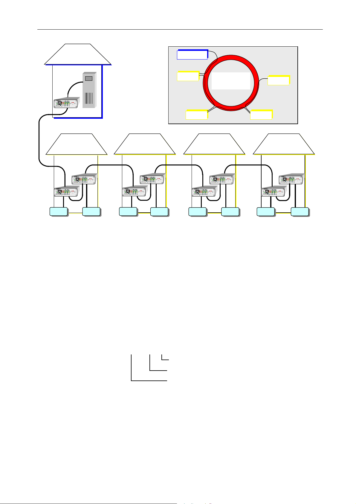
Figure 1-3 presents the option of applying EtherTel converters in network
management, supervision, configuration or monitoring applications. Using a single 2048 kbit/s
stream in SDH network, we can control devices located in remote facilities, distributed across a
large area. The host is connected via the converter to SDH network. There are two EtherTel
converters in each remote facility, connected to local Ethernet. One of the converters receives host
data via SDH network and transmits it to local area network, while the other converter transmits
the local area network data via SDH to consecutive facilities. In this configuration, two converters
perform the Add/Drop function for signal E1/G.703.
_______________________________________________________________________________
IOA78-1C 2 January 2005
Page 8
10Base-T/100Base-TX/E1 converter
l
A
ACTA
2
l
A
ACTA
2
l
A
T
A
l
A
l
A
R
l
A
R
l
A
R
2
2
MANAGEMENT
CENTER
Host
Ethernet
EtherTel
EtherTe
CT
1
LOS
LOF
LNK
LNK
TXD
LOOP2
IS
LOOP1
4-SG
ERR
RXD
RS-232
10/100
10/100
5-RxD
FD/COL
FD/COL
DCE
6-TxD
10/100BASE-T
E1
MENAGEMENT
10/100BASE-T/E1 CONVERTER
E1/G.703
2048kbit/s
Operating Manual
MANAGEMENT
CENTER
OBJECT 1
OBJECT 2 OBJECT 3
SDH RING
OBject 4
Object 1
EtherTe
C
21
ACT
LOS
LOF
LNK
LNK
TXD
LOOP2
IS
LOOP1
4-SG
ERR
RXD
RS-232
10/100
10/100
5-RxD
FD/COL
FD/COL
DCE
6-TxD
10/100BASE-T
E1
MENAGEMENT
10/100BASE-T/E1 CONVERTER
EtherTe
CT
1
LNK
LOS
LOF
LNK
TXD
LOOP2
IS
LOOP1
4-SG
ERR
RXD
RS-232
10/100
10/100
5-RxD
FD/COL
FD/COL
DCE
6-TxD
10/100BASE-T
E1
MENAGEMENT
10/100BASE-T/E1 CONVERTER
Ethernet
Switch Switch
E1/G.703
2048kbit/s
Object 2 Object 3 Object 4
E1/G.703
2048kbit/s 2048kbit/s
EtherTe
CT
21
ACT
LNK
LOS
LOF
LNK
TXD
LOOP2
LOOP1
AIS
4-SG
RXD
ER
RS-232
10/100
10/100
5-RxD
FD/COL
FD/COL
DCE
6-TxD
10/100BASE-T
E1
MENAGEMENT
10/100BASE-T/E1 CONVERTER
EtherTe
CT
21
ACT
LNK
LOS
LOF
LNK
TXD
LOOP2
LOOP1
AIS
4-SG
ERR
RXD
RS-232
10/100
10/100
5-RxD
FD/COL
FD/COL
DCE
6-TxD
10/100BASE-T
E1
MENAGEMENT
10/100BASE-T/E1 CONVERTER
CT
LOS
LOF
LNK
TXD
AIS
4-SG
RXD
ER
RS-232
10/100
5-RxD
FD/COL
DCE
6-TxD
10/100BASE-T
E1
MENAGEMENT
10/100BASE-T/E1 CONVERTER
Ethernet Ethernet
Switch
Switch Switch Switch Switch Switch
EtherTe
21
ACT
LNK
LOOP1
10/100
FD/COL
Ethernet
21
LOS
LOF
ACTLNK
TXD
LNK
AIS
ERR
RXD
4-SG
RS-232
10/100
10/100
5-RxD
FD/COL
DCE
6-TxD
10/100BASE-TE1
MENAGEMENT
10/100BASE-T/E1 CONVERTER
LOOP2
E1/G.703
EtherTel
ACT
LOOP2
LOOP1
FD/COL
EtherTel
1
LOS
LOF
ACTLNK
ACT
TXD
LNK
LOOP2
LOOP1
AIS
ERR
RXD
4-SG
RS-232
10/100
10/100
5-RxD
FD/COL
FD/COL
DCE
6-TxD
10/100BASE-TE1
MENAGEMENT
10/100BASE-T/E1 CONVERTER
EtherTe
CT
1
ACT
LNK
LOS
LOF
LNK
TXD
LOOP2
LOOP1
AIS
4-SG
RXD
ER
RS-232
10/100
10/100
5-RxD
FD/COL
FD/COL
DCE
6-TxD
10/100BASE-T
E1
MENAGEMENT
10/100BASE-T/E1 CONVERTER
Figure 1-3: Example application III.
1.3. Integration with other manufacturers’ equipment
From the E1/G.703 interface, the converter may work with other manufacturers’
equipment if they use HDLC (High Level Data Link Control) bit transmission protocol for
transport of Ethernet frames.
From the Ethernet interface, the converter may work with any equipment conforming to
10BASE-T and 100BASE-TX standard.
1.4. Labeling
Device:
TM-78.1
Device version
Device type
Telecommunication device
_______________________________________________________________________________
IOA78-1C 3 January 2005
Page 9
10Base-T/100Base-TX/E1 converter
A
A
2
Operating Manual
2. CONNECTORS AND LED INDICATORS
2.1. Front panel
LOS
LOF
TXD
EtherTel
1
CT
LNK
CT
LNK
LOOP1
FD/COL
RS-232
MENAGEMENT
1
4-SG
5-Rx
6-Tx
2
AIS
E1
ERR
RXD
10/100
FD/COL
10/100BASE-T
10/100
10/100BASE-T/E1 CONVERTER
3
4
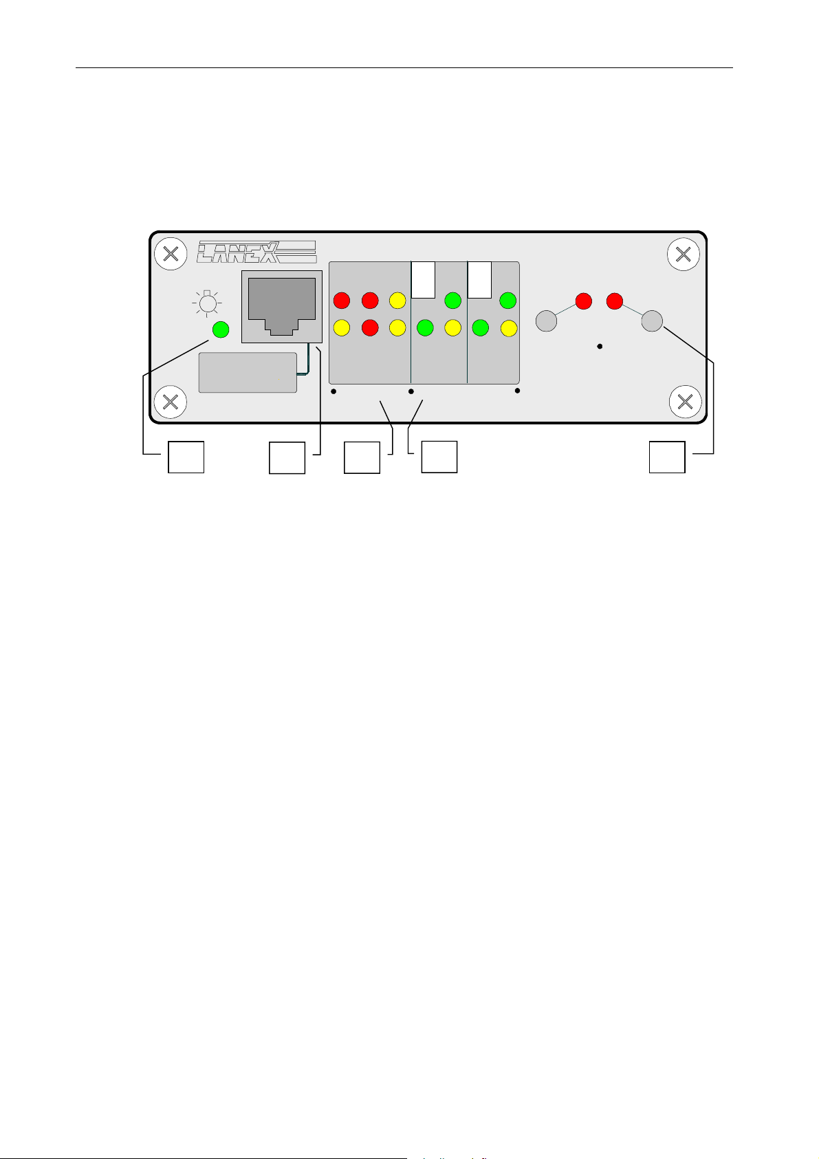
Figure 2-1: Layout and description of the front panel.
1. Power supply status LED
2. Monitoring and surveillance connector RS-232
3. Group of LEDs signaling conditions detected by the E1 local interface:
• LOS – Loss of Signal
• LOF – Loss of Frame
•
ERR – excess of errors rate 10
-5
and 10
-3
• AIS – Alarm Indication Signal
• TXD – Transmit Data to WAN
• TXD – Receive Data from WAN
4. Group of LEDs signaling conditions detected by Ethernet interfaces:
LOOP2
5
• LNK/ACT – loss of received signal/line activity; the LED is lit if no Ethernet signal is
lost, or blinks when data is being transmitted
• 10/100 – 10BaseT/100BaseTX; the LED is lit for 100Base-TX
• FD/COL – full duplex/half-duplex (collision signaling); the LED is on for full duplex
and blinks in case of collision
5. Group of switches and LEDs signaling closing of test loops:
• LOOP1 – local analog loop (rules of application specified under 3.4)
• LOOP2 – remote digital loop (rules of application specified under 3.4)
_______________________________________________________________________________
IOA78-1C 4 January 2005
Page 10
10Base-T/100Base-TX/E1 converter
2.2. Rear panel
Operating Manual
5V
MDI 1 MDI 2 MDIX 2
10/100BASE-T
1 2 3 4 5
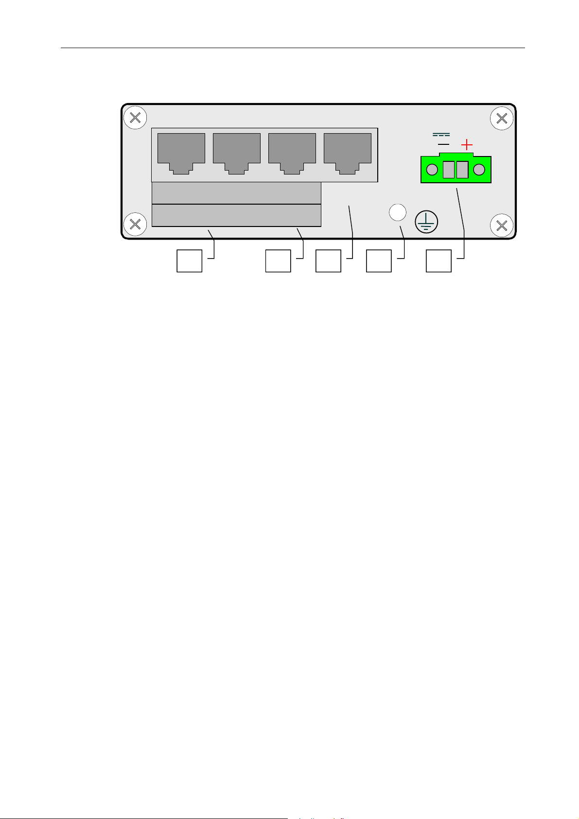
Figure 2-2: Layout and description of the rear panel.
1. Ethernet interface jacks port 1 and 2 MDI
2. Ethernet interface jack port 2 MDIX
3. E1/G.703 interface jack 120 Ω - RJ-45
4. Earthing clamp
5. Power supply connector
E1
_______________________________________________________________________________
IOA78-1C 5 January 2005
Page 11
10Base-T/100Base-TX/E1 converter
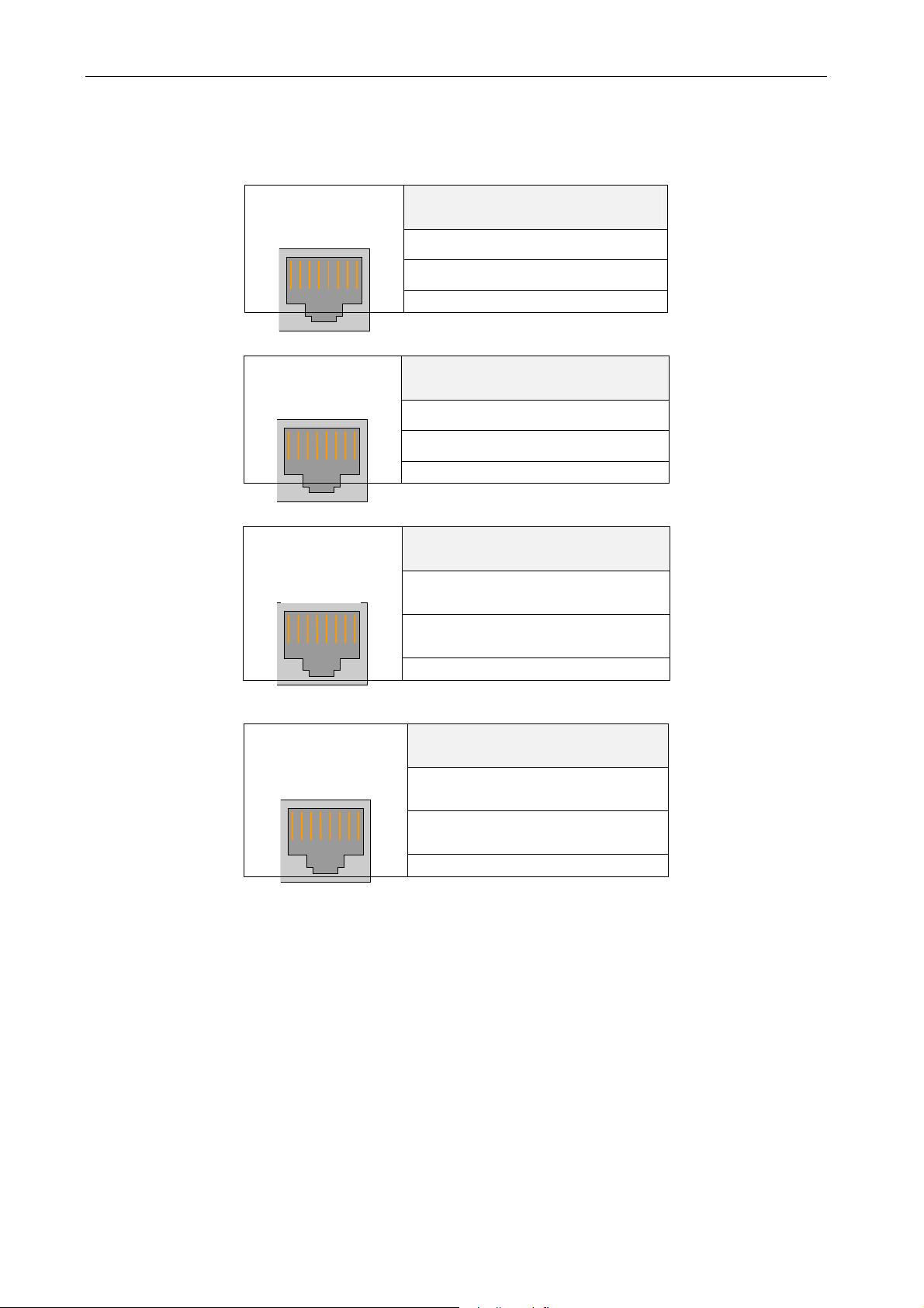
2.3. Description of connectors
1
Figure 2-3: RJ-45 surveillance connector
1
Figure 2-4: E1/G.703. interface connector
1
Figure 2-5: Ethernet MDI interface connector - port 1 and 2.
1
Figure 2-6: MDIX Ethernet interface connector - port 2.
8
8
8
8
Operating Manual
Description of RJ-45
connector
4 – Supply common
5 – RXD
6 – TXD
Description of RJ-45
connector
1,2 – E1/G.703 signal input
3,6 – E1/G.703 signal output
Description of RJ-45
connector
1 - + Ethernet signal input
2 - - Ethernet signal input
3 - + Ethernet signal output
6 - - Ethernet signal output
Description of RJ-45
connector
1 - + Ethernet signal output
2 - - Ethernet signal output
3 - + Ethernet signal input
6 - - Ethernet signal input
_______________________________________________________________________________
IOA78-1C 6 January 2005
Page 12

10Base-T/100Base-TX/E1 converter
Operating Manual
3. FUNCTIONAL DESCRIPTION
3.1. Rule of operation
The converter is equipped with 3 ports. Two ports are used for connecting external
network segments. One port is equipped with an MDI output jack and the other has two output
jacks, an MDI and an MDIX (switched transmission and reception signals cables). The Ethernet
segment can only be connected in the second port to one of the MDI or MDIX jacks. Regardless
of the device connected (NIC, hub, switch), ‘straight’ cable can always be used for that port. The
third port is used for connecting E1/G.703 line.
Ethernet frame received from any port, located in time slots of G.704 frame in the form of
digital channel n x 64 kbit/s, n from 1 to 31 and sent to PDH or SDH telecommunication network
through G.703 interface. To the opposite direction of transmission, G.704 frame is received from
the telecommunication network, Ethernet frame is extracted and sent to a relevant port of the
switch, depending on where the connected station is located. The device filters local traffic within
Ethernet network connected to switch ports and only retransmits inter-network traffic to remote
network segments. Device configuration and operation status monitoring, as well as operation of
the managing application with LNMP protocol is performed through RS-232 electrical interface.
The Ethernet interface serves two implementations of the physical layer, rated 10 Mbit/s
and 100 Mbit/s, with an option of automatic negotiation, which ensures connection at a maximum
available rate – Table 3-1. The mode of connection is signaled by LEDs on the front wall.
Table 3-1. Sequence of connection choice in automatic negotiation
Sequence Connection mode
1 100BASE-TX full-duplex
2 100BASE-TX
3 10BASE-T full-duplex
4 10BASE-T
The converter regularly reviews the stored addresses in the MAC source address table,
deleting the ones residing there for over 300 seconds.
3.2. Clock
The converter may send data to transmission direction E1/G.703 with a clock from two
sources:
• from internal quartz generator, frequency 2.048 MHz ±50 ppm, operating in MASTER
mode
• from clock retrieval systems of opposite direction of transmission E1/G.703, operating in
SLAVE mode
3.3. Diagnostic and signaling systems
The converter automatically checks the parameters of line interface E1/G.703 and Ethernet
interface signal. It detects and signals the following conditions and volumes:
E1/G.703, G.704 line interface:
• loss of signal at interface input
• loss of frame
• excess of error rate (violation of HDB3 code) 1x10
-3
and 1x10
-5
in incoming signal
• AIS signal receipt
• receipt of alarm bit from remote device in zero slot of G.704 frame
_______________________________________________________________________________
IOA78-1C 7 January 2005
Page 13

10Base-T/100Base-TX/E1 converter
Operating Manual
Ethernet interface:
• loss of connection
• packets transmission
• port configuration following automatic negotiation
Alarm conditions are signaled through:
• relevant LED of E1 line interface being lit: LOS, LOF, ERR, AIS,
• relevant LED of Ethernet interface not being lit: LNK/ACT
Table 3-2. Detected emergency conditions and accompanying actions.
L
E
D
L
L
E
E
D
D
L
L
O
O
S
F
None
Emergency condition
Ethernet interface Loss of connection integrity signal
Loss of signal Setting of A bit in TS0
1)
-5
-3
Line interface
E1
G.703, G.704
Remote device
Loss of frame
Errors rate > 10
Errors rate > 10
Occurrence of bit A in TS0 from remote
device
L
N
K
/
A
C
K
☼
Setting of A bit in TS0
Setting of A bit in TS0
L
L
E
E
D
D
E
A
R
I
R
S
None
2)
Action taken
None
– the LED is lit
☼ - the LED is off
1)
– urgent alarm is not generated when loss of frame is caused by receipt of AIS signal
2)
– LED blinks
3.4. Test loops
The converter enables activation of two types of test loops:
• Local analog loop marked as LOOP1
• Remote digital loop marked as LOOP2
Activation and deactivation of test loops from E1 interface is possible using:
• buttons on the front panel of the device: Figure 2-1
• dedicated application on Windows 9x/2000/NT.
The LOOP2 remote loop may only be activated when the E1 interface is configured in framed
mode, when a service channel exists between the two devices.
_______________________________________________________________________________
IOA78-1C 8 January 2005
Page 14
10Base-T/100Base-TX/E1 converter
A
A
2
A
A
2
l
A
K
A
2
l
K
A
A
2
l
K
A
A
2
Operating Manual
Use of diagnostic loops is only justified during installation of devices, for
testing tract E1/G.703.
The loops may not be activated during normal operation with other
Ethernet devices connected.
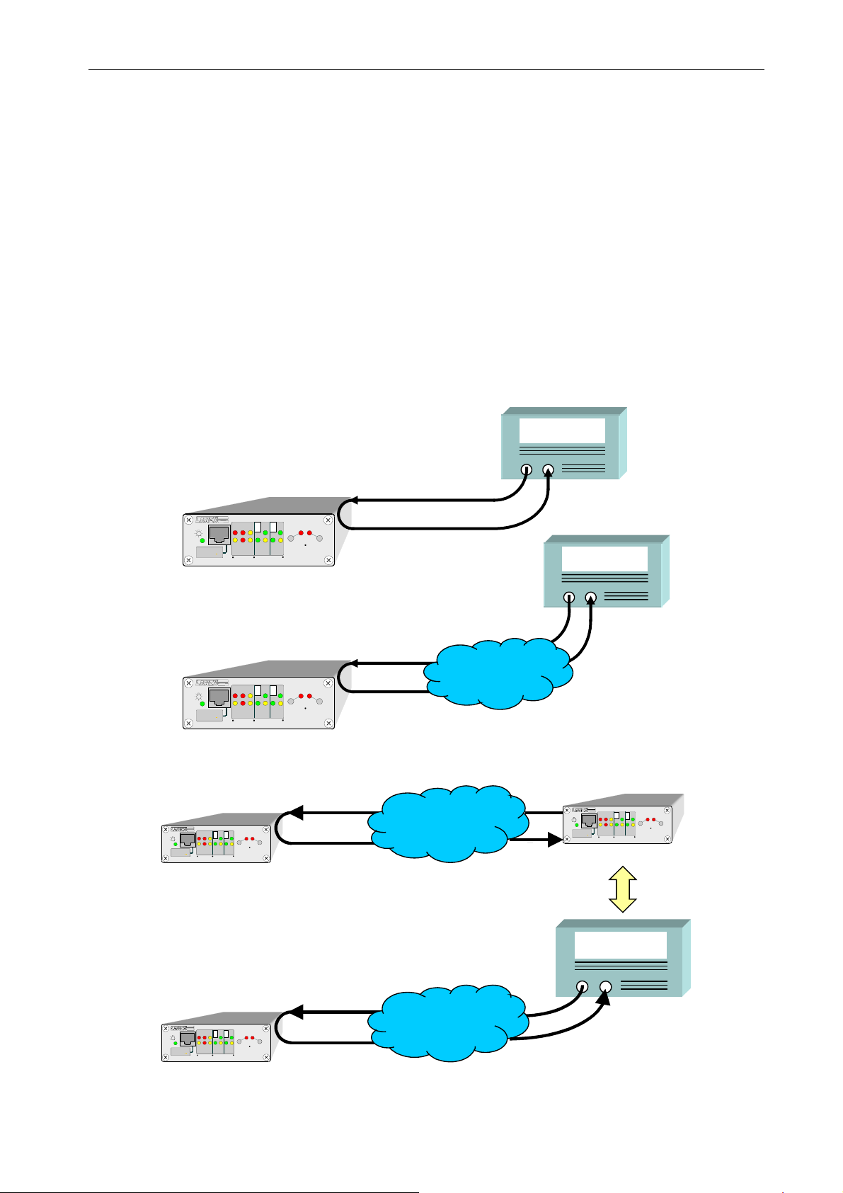
The use of the LOOP1 local loop is only allowed for the purpose of checking correctness
of connections of the telecommunication route using PCM transmission analyzer. It may not be
switched on if
3-1.
The rules of using the LOOP2 remote loop are the same as for LOOP1. To use the remote
loop, G.703 interfaces of the converters should be connected to line and the loop should be closed.
On Figure 3-2 converter 2 activates the remote loop in converter 1.
Then it is disconnected and a PCM transmission analyzer can be connected in its place to
take measurements of the route. The time between disconnecting the converter and connecting the
analyzer may not exceed 10 s, as after that time the loop disconnects automatically.
EtherTel devices are connected on both ends of the telecommunication line. Figure
PCM TRANSMISSION
ANALYZER
E1/G.703
PCM TRANSMISSION
ANALYZER
RS-232
DCE
MENAGEMENT
LOF
LNK
LNK
TXD
ERR
RXD
10/100
10/100
FD/COL
10/100BASE-T
E1
10/100BASE-T/E1 CONVERTER
ACT
LOOP2
LOOP1
FD/COL
LOS
IS
4-SG
5-RxD
6-TxD
EtherTel
CT
1
EtherTel
LOS
IS
4-SG
RS-232
5-RxD
DCE
6-TxD
MENAGEMENT
E1
EtherTel
CT
1
ACT
LOF
LNK
LNK
TXD
ERR
RXD
10/100
10/100
FD/COL
FD/COL
10/100BASE-T
10/100BASE-T/E1 CONVERTER
EtherTel
LOOP2
LOOP1
Telecommunication
E1/G.703
network
Figure 3-1: Rules of introducing and using the LOOP1 local loop.
LOS
LOF
IS
4-SG
ERR
RS-232
5-RxD
DCE
6-TxD
E1
MENAGEMENT
EtherTel 2
EtherTe
CT
1
ACT
LNK
TXD
LN
LOOP1
RXD
10/100
10/100
FD/COL
FD/COL
10/100BASE-T
10/100BASE-T/E1 CONVERTER
Telecommunication
E1/G.703
LOOP2
network
4-SG
RS-232
5-RxD
DCE
6-TxD
MENAGEMENT
EtherTel 1
CT
1
LOS
LOF
TXD
LN
IS
ERR
RXD
10/100
FD/COL
10/100BASE-T
E1
10/100BASE-T/E1 CONVERTER
LNK
10/100
EtherTe
ACT
LOOP1
FD/COL
LOOP2
PCM TRANSMISSION
ANALYZER
Telecommunication
LOS
LOF
IS
4-SG
ERR
RS-232
5-RxD
DCE
6-TxD
E1
MENAGEMENT
EtherTel 2
EtherTe
CT
1
ACT
LN
LNK
TXD
LOOP1
RXD
10/100
10/100
FD/COL
FD/COL
10/100BASE-T
10/100BASE-T/E1 CONVERTER
E1/G.703
LOOP2
network
Figure 3-2: Rules of introducing and using the LOOP2 remote loop.
_______________________________________________________________________________
IOA78-1C 9 January 2005
Page 15

10Base-T/100Base-TX/E1 converter
Operating Manual
3.5. Quality management
Quality management refers to surveillance of transmissoin quality in line G.703/E1
ensured by the device, and to package transmission between LAN and WAN ports.
Quality surveillance between LAN and WAN ports consists in monitoring the transmitted
packages and registration of bad packages. Transmission quality assessment is the proportion of
the number of bad packages to all packages transmitted in the given time.
Quality surveillance of line E1/G.703 consists in recording quality-related transmission
events that can be used for assessing transmission and service quality according to G.826. The
following should be used as a basis of quality assessment:
• number of errored seconds - ES
• number of severely errored seconds - SES
• number of errored blocks – EB
• proportion of errored seconds to all seconds when the device is available – ESR [%]
• proportion of severely errored seconds to all seconds when the device is available – SESR [%]
• proportion of errored blocks to all blocks when the device is available – BBER [%]
• number of device availability seconds - AS
• number of device unavailability seconds – UAS, 10 consecutive SES change the line status to
unavailable, 10 seconds without SES restores the availability status
• total number of seconds of operations from the point of switching on the device – TS
AS value = TS – UAS
Table 3-3. Event table. specifies the manner of interpretation of events from the receiving
direction for 2048 kbit/s signal.
Table 3-3. Event table.
Type of event per 1 second
Interpretatio
n
1 LOS - loss of signal at input ES + SES
1 HDB3 code error ES
1 LOF – loss of frame ES + SES
1 AIS – alarm indication signal ES + SES
10-6 – error rate ES
10-3 – error rate SES
1 FAS – errors in synchronization pattern ES
28 FAS ES + SES
1 CRC-4 – control sequence ES
805 CRC-4 ES + SES
The number of events related to quality of threshold excess is counted in 15-minute and
24-hour cycles in registries located in the device.
The 15-minute logs form a stack of at least 16 logs of past periods. When all logs are full,
the contents of the oldest 15-minute cycle logs can be lost.
The operator can read and set thresholds for 15-minute and 24-hour logs. Quality
thresholds for a 15-minute cycle should be set in a range from 1 to 900, with the following
recommended default values: 120 for ES and 15 for SES. No threshold values are specified in
standards for the 24-hour cycle. Quality thresholds for the 24 h cycle should be set within a range
from 0 to 86400.
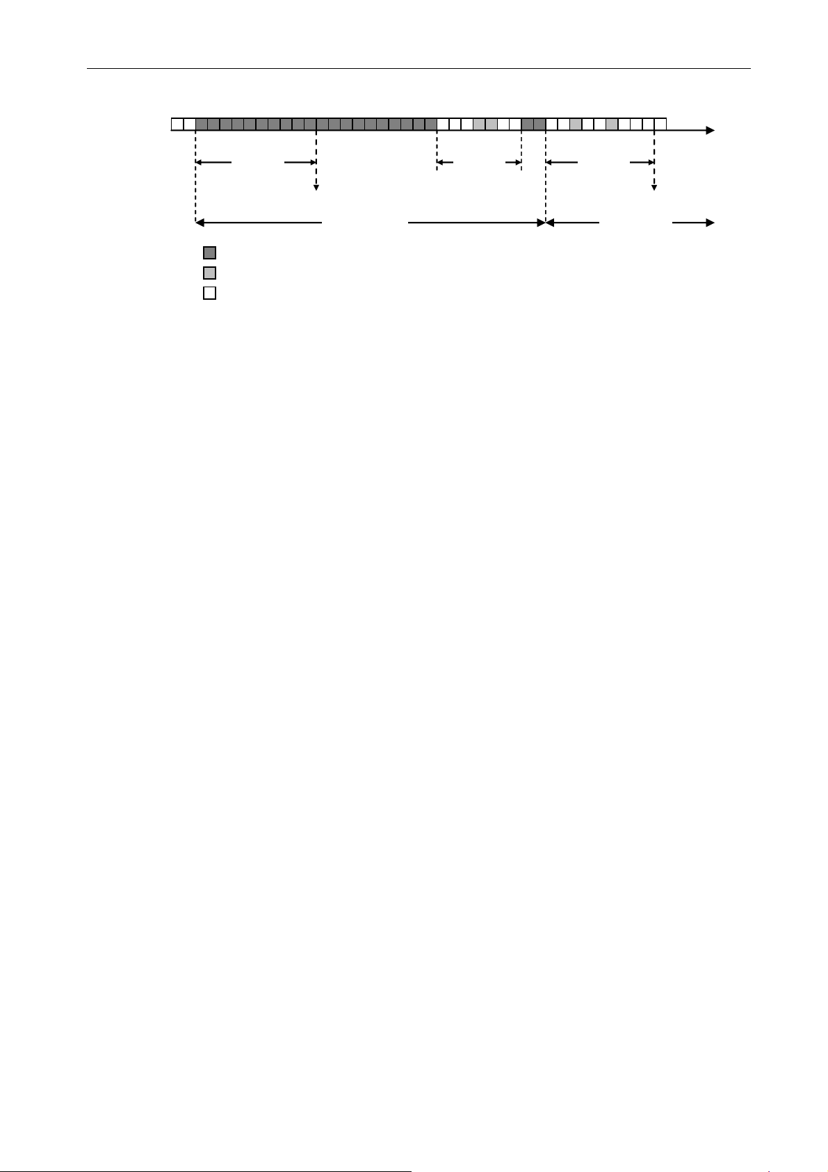
Device unavailability definitions are presented in Figure 3-3.
_______________________________________________________________________________
IOA78-1C 10 January 2005
Page 16
10Base-T/100Base-TX/E1 converter
A
A
Operating Manual
10 seconds 10 seconds 10 seconds
Unavailability detection
Unavailable period
Severely errored second
Errored second, no SES
Unerrored second
vailability detection
vailable period
Time
Figure 3-3: Device unavailability.
3.6. Event log
The converter has a function of registering the time and date of occurrence of an event with
a specified criteria. The following types of events are included here:
• occurrence or loss of signal at input of the E1 line interface
• synchronization or loss of synchronization of E1 connection
• synchronization or loss of synchronization of E1 frame
• excess or below threshold value of block error rate of 10
-3
of signal received from E1 line
interface
• excess or below threshold value of block error rate of 10
-5
of signal received from E1 line
interface
• excess or below user-defined threshold value of counts of the 15-minute ES counter
(ES15)
• excess or below user-defined threshold value of counts of the 24-hour ES counter (ES24)
• excess or below user-defined threshold value of counts of the 15-minute SES counter
(SES15)
• excess or below user-defined threshold value of counts of the 24-hour SES counter
(SES24)
• connection or disconnection of test loops
• approval of change in device configuration
• attempt at unauthorized access to device configuration system using VT-100 terminal
emulator in case of password protection
Viewing and clearing the event log, as well as defining maximum and minimum threshold
values for the ES15, ES24 and SES15, SES24 counters of the E1 interface is possible using the
LanWin application, described in chapter 5.
3.7. Service channels
Managing applications developed for the converter enable managing the local device, as
well as the remote device using service channels. These are dedicated Windows 9x/2000/NT
platform applications LanWin and VT-100 terminal emulator software, enabling only local device
management.
In the case of G.703 interface, such channel can be created on any single slot of the G.704
stream with a flow capacity of 64 kbit/s. A channel may also be created on slot 0 (TS0), while it
should be noted that the flow capacity of such service channel will be only 20 kbit/s. A slot for a
service channel of the E1 interface can be selected from the managing application level.
In case of E1 interface configuration into non-framed mode, converters can no longer
manage the remote device connected on the side of the E1 interface. This is due to their inability
to select the surveillance slot.
_______________________________________________________________________________
IOA78-1C 11 January 2005
Page 17

10Base-T/100Base-TX/E1 converter
Operating Manual
4. INSTALLATION & OPERATION
4.1. Introduction
Proper installation and configuration of the device in accordance with guidelines contained in
the following sections of this manual is required before commencement of operation.
4.2. Working conditions
The converter may work in continuous mode indoors, in conditions specified in Technical
Data
. It should not be exposed to direct sunlight. The device should not be placed on heat sources,
although it may be put on another device of the same type or on a rack with other operating
devices. In this latter case, free air circulation or forced ventilation when necessary should be
provided.
4.3. Power Supply
The converter is supplied with the following voltage: 4.5 – 5.5 VAC. Supply voltage with
proper polarization must be provided. The converter is supplied with 4,5
polarization on the supply connection. Power supply should be connected to the jack with external
bolted clamps. Polarity of supply voltage is described on the rear plate Figure 2-2.
Earth should be connected to the earthing clamp on the housing. The earthing wire should
be of low impedance type for high frequencies.
Proper power supply is signaled with a green LED lit on the front panel of the device.
A Mascot power supply unit type 5015, 230VAC/4,5VDC is recommended for supplying 230
VAC from the power network, with marked polarization cable. Grey, white or red color on one of
the cores means „
Optionally, ECD1-R2-48s05 type power supply by Merawex can be used, which enables
supplying the converter from 48 VDC. The power supply unit can be mounted to the DIN rail or
to a flat area with a velcro. The power supply unit is equipped with clamped connections. To
attach a cable, insert a screwdriver in one of the openings, causing the clamps to open, then insert
a cable in the other opening and remove the screwdriver. Properly fixed cable should not slip
away from the connector. Polarity of the
on the housing. Connect „
The scope of delivery contains two-core cable with polarity marking for simple connection of
power supply, one core being red and black, the other being black.
The manufacturer guarantees conformity with safety and electromagnetic compatibility
standards for operation with such power supply units.
+”, all black core means „-”.
+48 V input voltage and +5 V output voltage is described
+” of the power supply unit with „+” of the converter and „-” with „-”.
÷5,5 VDC, maintaining
! The device is not provided with an integrated tripping system. Therefore, an easily
available tripping system should be mounted in fixed cabling.
_______________________________________________________________________________
IOA78-1C 12 January 2005
Page 18
10Base-T/100Base-TX/E1 converter
4.4. Connecting connection cables
4.4.1. Ethernet interface
Operating Manual
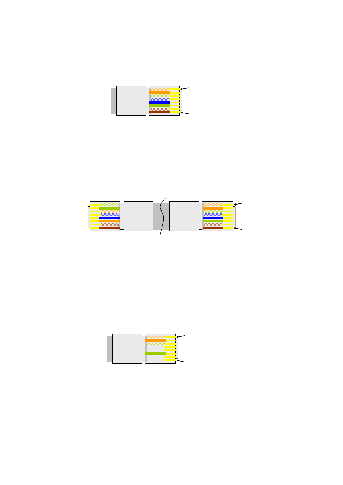
Pin1
Pin8
1 White-orange
2 Orange
3 White-green
4 White-blue
5 Blue
6 Green
7 White-brown
8 Brown
Figure 4-1: Ethernet interface RJ-45 male connector.
Connecting cable connectors Figure 4-1 should be terminated in the same way on both
ends, spiral colors must be clamped on the same appropriate pins in case of straight cable. Straight
cable is used for connecting network interface cards with converter MDI ports and for connecting
switches or hubs with MDI-X port. Crossed cable can be used for connecting network interface
cards with the MDI-X port of the converter and for connecting switches or hubs with MDI ports.
Crossed cable is shown on Figure 4-2. .
1 White-green
2 Green
3 White-orange
4 White-blue
5 Blue
6 Orange
7 White-brown
8 Brown
Pin1
Pin8
1 White-orange
2 Orange
3 White-green
4 White-blue
5 Blue
6 Green
7 White-brown
8 Brown
Figure 4-2: Method of connecting crossed cable.
4.4.2. E1/G.703 line interface
Input and output signals of the E1/G.703 interface should be supplied by two symmetrical
screening cables, impedance 120
Ω, or by one double screening cable with the same impedance
value. The input signal should be supplied to pins 1 and 2, while output signal should be led out of
pins 3 and 6 (Figure 4-3). To meet disturbance emission requirements, the following rules should
be obeyed. Symmetrical cables should be connected with an RJ-45 pin equipped with metal or
metallized casing (tubing). Cable screen should connect to the casing.
Pin1
Pin8
1 White-orange
2 Orange
3 White-green
4 Not connected
5 Not connected
6 Green
7 Not connected
8 Not connected
Figure 4-3. E1/G.703. interface RJ-45 male connector.
Description of terminals on E1/G.703 line interface connector is presented on Figure 4-2.
_______________________________________________________________________________
IOA78-1C 13 January 2005
Page 19
10Base-T/100Base-TX/E1 converter
Operating Manual
4.5. Attachment of surveillance cables
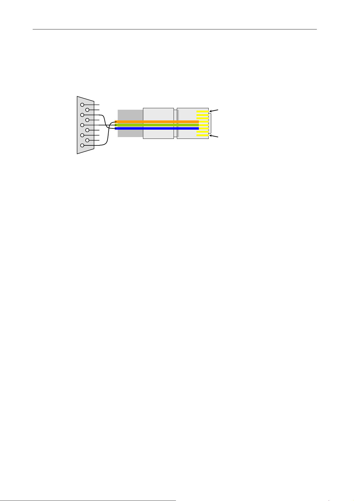
So that management of devices is possible, the monitored device must be connected with a
PC with LanWin software or VT-100 terminal emulator installed. Connection shall be made with
RS-232 cable, specification as provided on Figure 4-4.
1
6
2
7
3
8
4
9
5
Pin1
Pin8
1 Not connected
2 Not connected
3 Not connected
4 GND
5 RXD
6 TXD
7 Not connected
8 Not connected
Figure 4-4: RS-232 cable with DB-9
RJ-45 pins.
_______________________________________________________________________________
IOA78-1C 14 January 2005
Page 20

10Base-T/100Base-TX/E1 converter
Operating Manual
4.6. Clock setup
Three variants of converter operation are possible. The converters may transmit data,
depending on conditions and capacity of the telecommunication network, in the following layouts:
• MASTER-MASTER
• MASTER-SLAVE
• SLAVE-SLAVE
The converter operates in MASTER mode when the clock source for data transmitted to
the E1/G.703 interface is the clock from internal quartz generator. In
SLAVE mode, clock source
for data transmitted to the E1/G.703 interface is the clock retrieved from the opposite direction of
transmission.
MASTER-MASTER mode, both converters work with their own internal clocks –
In
plesiochronous transmission. Possible work with PDH and SDH systems configured in
asynchronous mode.
MASTER-SLAVE mode, the master works with internal clock and the slave works with
In
retrieved clock – synchronous transmission. Possible work with PDH and SDH systems
configured in asynchronous mode.
SLAVE-SLAVE mode, both converters work with retrieved clocks – synchronous
In
transmission. This configuration is only possible if the converters are connected to SDH
telecommunication network and the network operates in synchronous mode. Work with PDH
systems is not possible.
4.7. Configuration of the E1 G.703 interface
The converter has the following E1 G.703 interface configuration functions:
• CRC option available only in framing mode on
o switching this option on enables achieving proper integration with equipment that
requires transmission of the remainder of CRC division in zero slot C1-C4 bits
o switching this option off results in setting C bits of the zero slot in ‘1’ position
• Framing
o switching this option on enables proper integration with equipment operating with
G.704 framed signal and allows selection of a block of slots for transmission. In
addition, this option enables communication with the remote device on the side of
the E1 interface.
o option off results in blocked selection of slots, surveillance slot and CRC setting.
When the framing option is off, E1 stream is transmitted transparently. Therefore,
data can be transmitted at full speed of 2048 kbit/s.
• Multiframe
o Switching this option on enables proper integration with operating equipment that
uses the sixteenth slot for signals transmission.
o In this option, the sixteenth slot may not be used for data transmission
• Choice of surveillance slot number, to be used for managing the remote device connected
on the side of the E1 interface, option available only if framing is on.
_______________________________________________________________________________
IOA78-1C 15 January 2005
Page 21
10Base-T/100Base-TX/E1 converter
Operating Manual
5. CONVERTER SETUP WITH LANWIN SOFTWARE
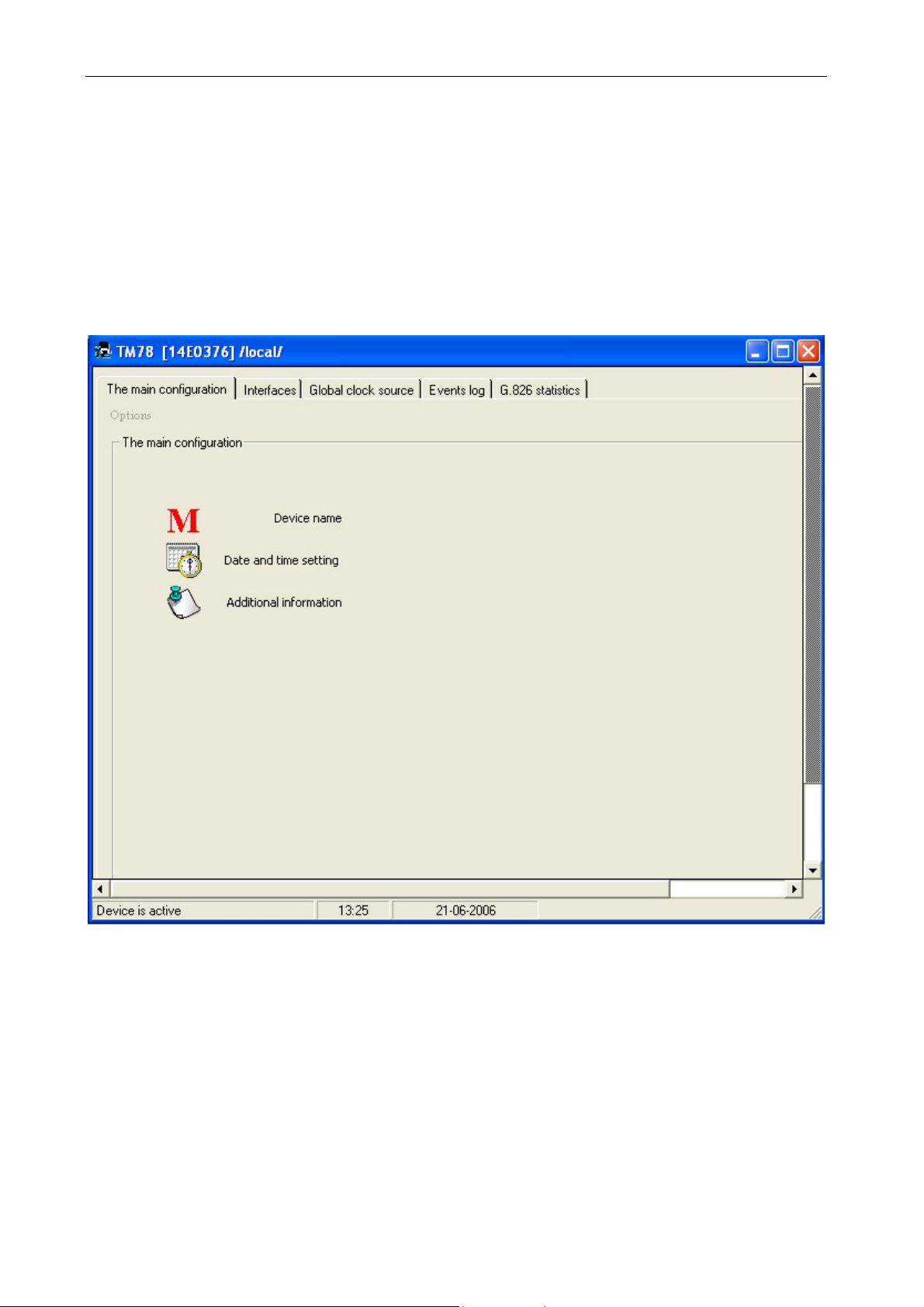
The LanWin application in its local version enables surveillance and monitoring of the TM-78
converter. Description of computer connection is contained in section 4.5.
5.1. Global setup
You can enter device name, set system date and time, or view additional information about the
equipment in this tab.
Figure 5-1: Global setup.
_______________________________________________________________________________
IOA78-1C 16 January 2005
Page 22
10Base-T/100Base-TX/E1 converter
Operating Manual
5.1.1. Device Name
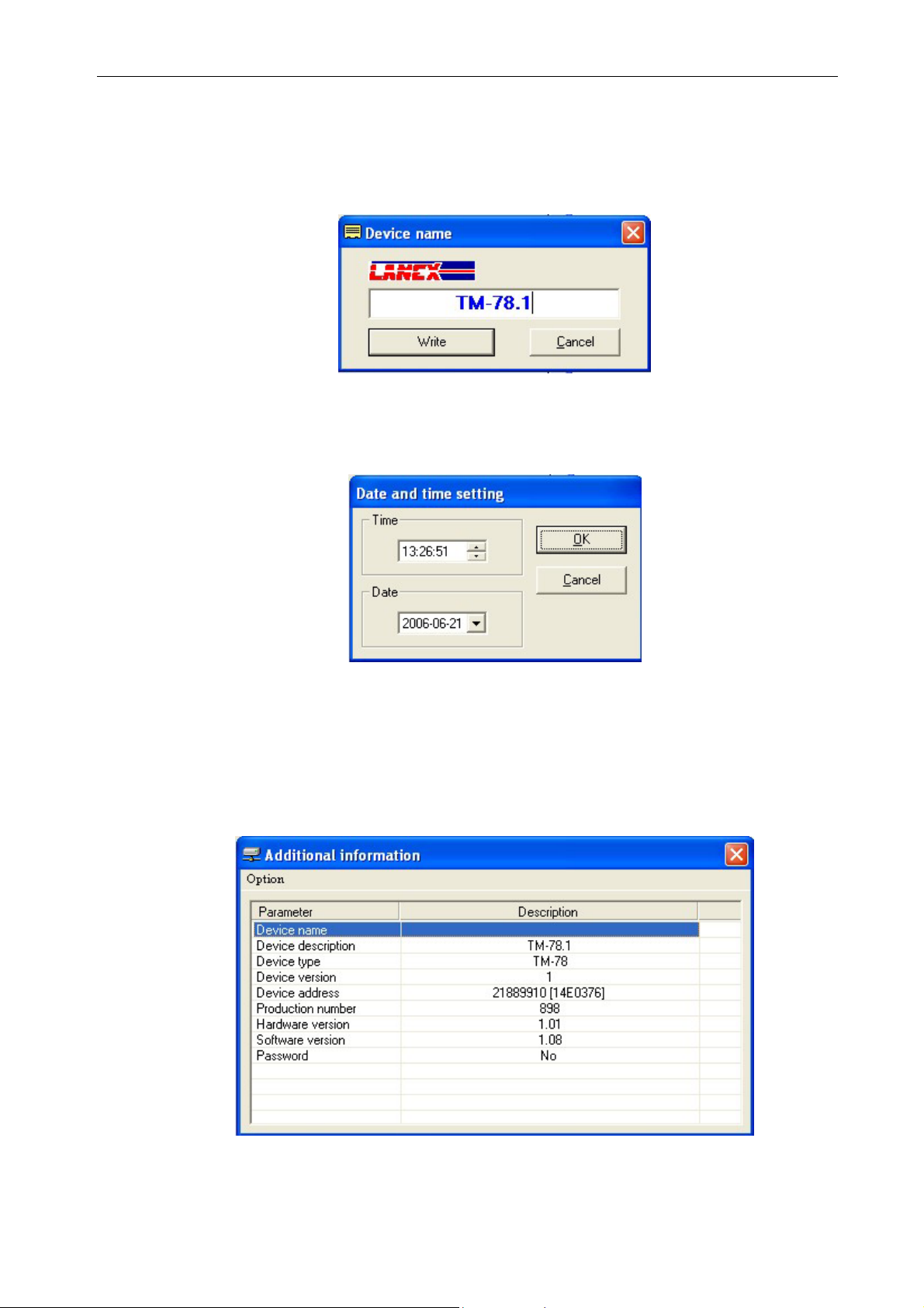
After you press the Device Name button, a window will open for entering the name.
During work with the device, the name entered here will appear in active devices window and in
the device window whose name was changed.
Figure 5-2: Device Name.
5.1.2. Date and time setting
When you press Time and date setting, the following window will be displayed.
Figure 5-3: Date and time setting
When you have made your changes and press
OK, they will be updated in the device.
5.1.3. Additional information
When you press Additional information, a window will be displayed containing additional
information about the connected device.
Figure 5-4: Additional information.
_______________________________________________________________________________
IOA78-1C 17 January 2005
Page 23
10Base-T/100Base-TX/E1 converter
Operating Manual
5.2. Interfaces
The Interfaces tab is designed for managing E1 and Ethernet interfaces. It contains
subtabs of the above interfaces. Each subtab enables independent configuration of work
parameters, monitoring and creating test loops.
5.2.1. E1, Setup tab
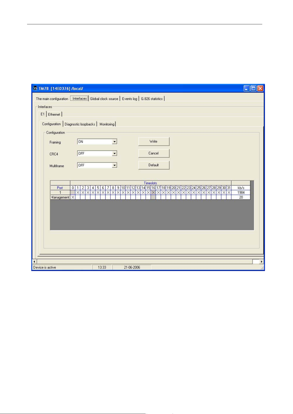
Figure 5-5: Interfaces - E1, Setup.
This module tab enables specifying mode of operation of the E1 interface, selecting
number of slots designed for transmission and determining location of the surveillance slot.
Selectable settings:
FRAMING ON-OFF
CRC ON-OFF
MULTIFRAME ON-OFF
A specific slot can be selected through checking a relevant box and saving the setting.
_______________________________________________________________________________
IOA78-1C 18 January 2005
Page 24
10Base-T/100Base-TX/E1 converter
5.2.1.1. E1, Loops tab
Operating Manual
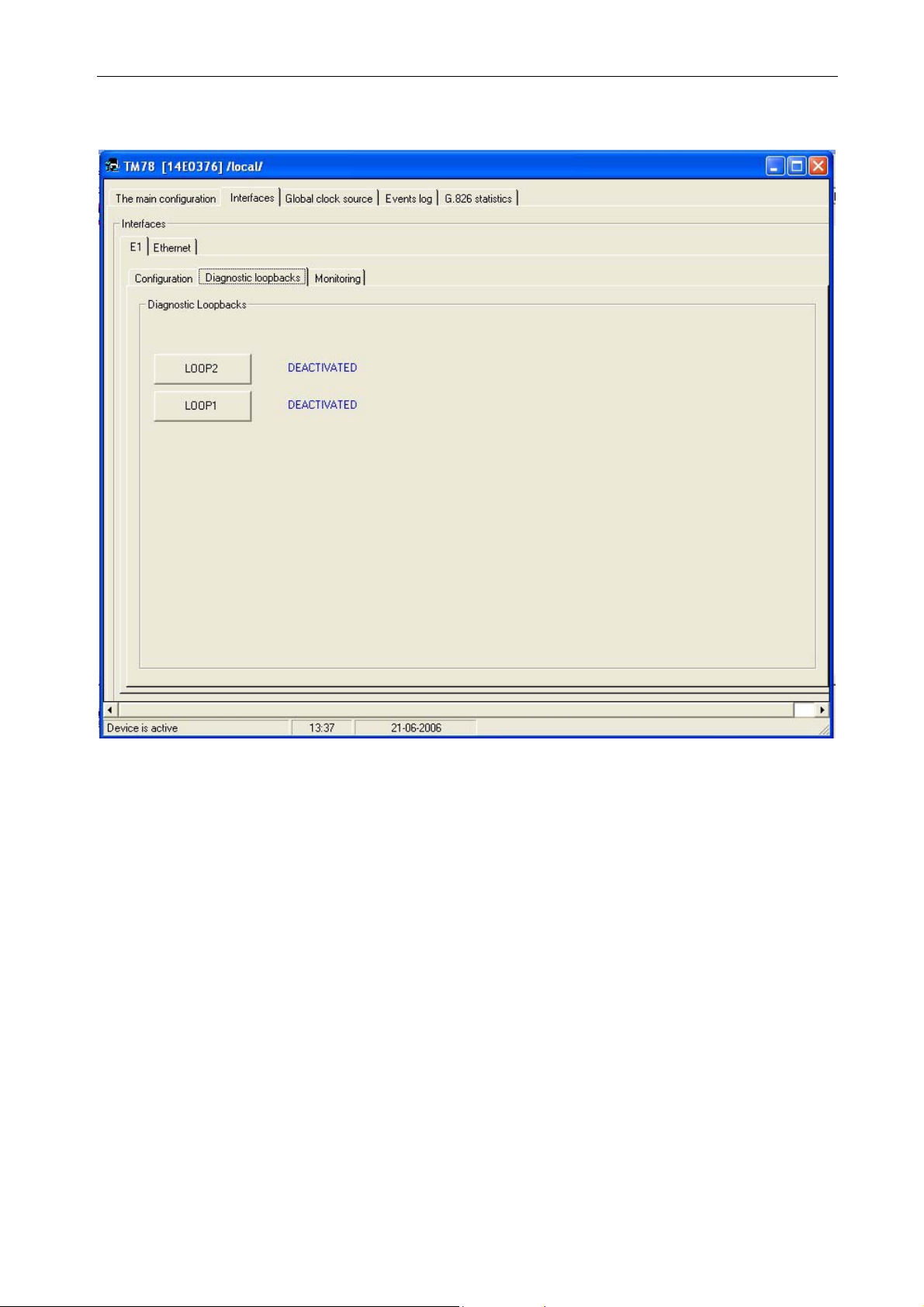
Figure 5-6: Interfaces - E1, Loops.
This tab allows activation of the following loops on the side of the E1 interface:
• local LOOP1
• remote LOOP2
The LOOP2 remote loop may only be activated when the E1 interface is configured in framed
mode, when a service channel exists between the two devices.
Use of diagnostic loops is only justified during installation of devices, for
testing tract E1/G.703.
The loops may not be activated during normal operation with other
Ethernet devices connected. Rules of application – see section 3.4.
_______________________________________________________________________________
IOA78-1C 19 January 2005
Page 25
10Base-T/100Base-TX/E1 converter
5.2.1.2. E1, Monitoring tab.
Operating Manual
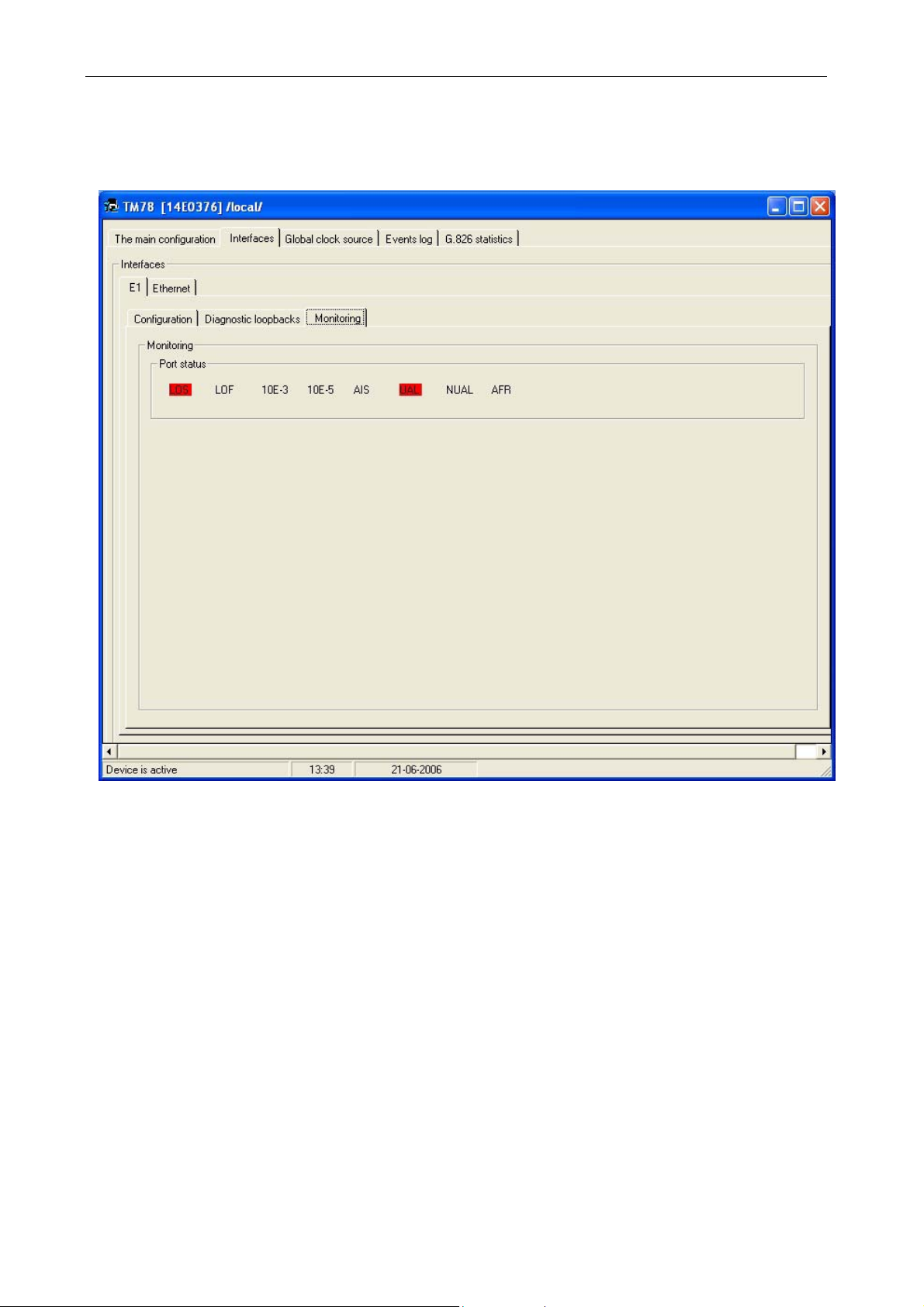
This tab enables viewing the E1 interface signaling. An event is signaled through
highlighting in red:
LOS - loss of signal
LOF - loss of frame,
10E-3 - excess of errors rate 10
10E-5 - excess of errors rate 10
AIS - Alarm Indication Signal
UAL - Urgent Alarm
NUAL - Non-urgent Alarm
RAL - Alarm from Remote Device
Figure 5-7: Interfaces - E1, Monitoring.
-3
-5
_______________________________________________________________________________
IOA78-1C 20 January 2005
Page 26
10Base-T/100Base-TX/E1 converter
5.2.1.3. Ethernet, Setup tab
Operating Manual
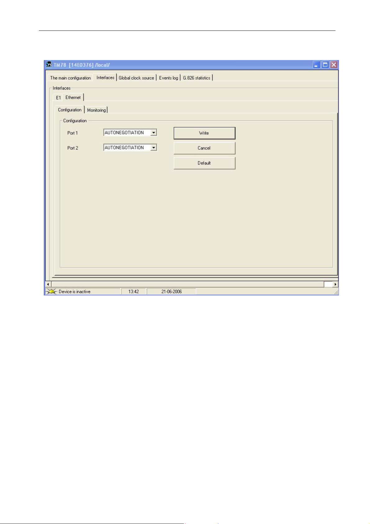
Figure 5-8: Interfaces - Ethernet, Setup.
In this tab, you can change transmission parameters of Ethernet interfaces. The following
modes of operation are available:
AUTONEGOTIATION – determining highest combined transmission rate
100Mbit/s – full duplex – enforced full duplex operation 100Mbit/s
100Mbit/s – half duplex – enforced half duplex operation 100Mbit/s
10Mbit/s – full duplex – enforced full duplex operation 10Mbit/s
10Mbit/s – half duplex – enforced half duplex operation 10Mbit/s
_______________________________________________________________________________
IOA78-1C 21 January 2005
Page 27
10Base-T/100Base-TX/E1 converter
5.2.1.4. Ethernet, Monitoring tab.
Operating Manual
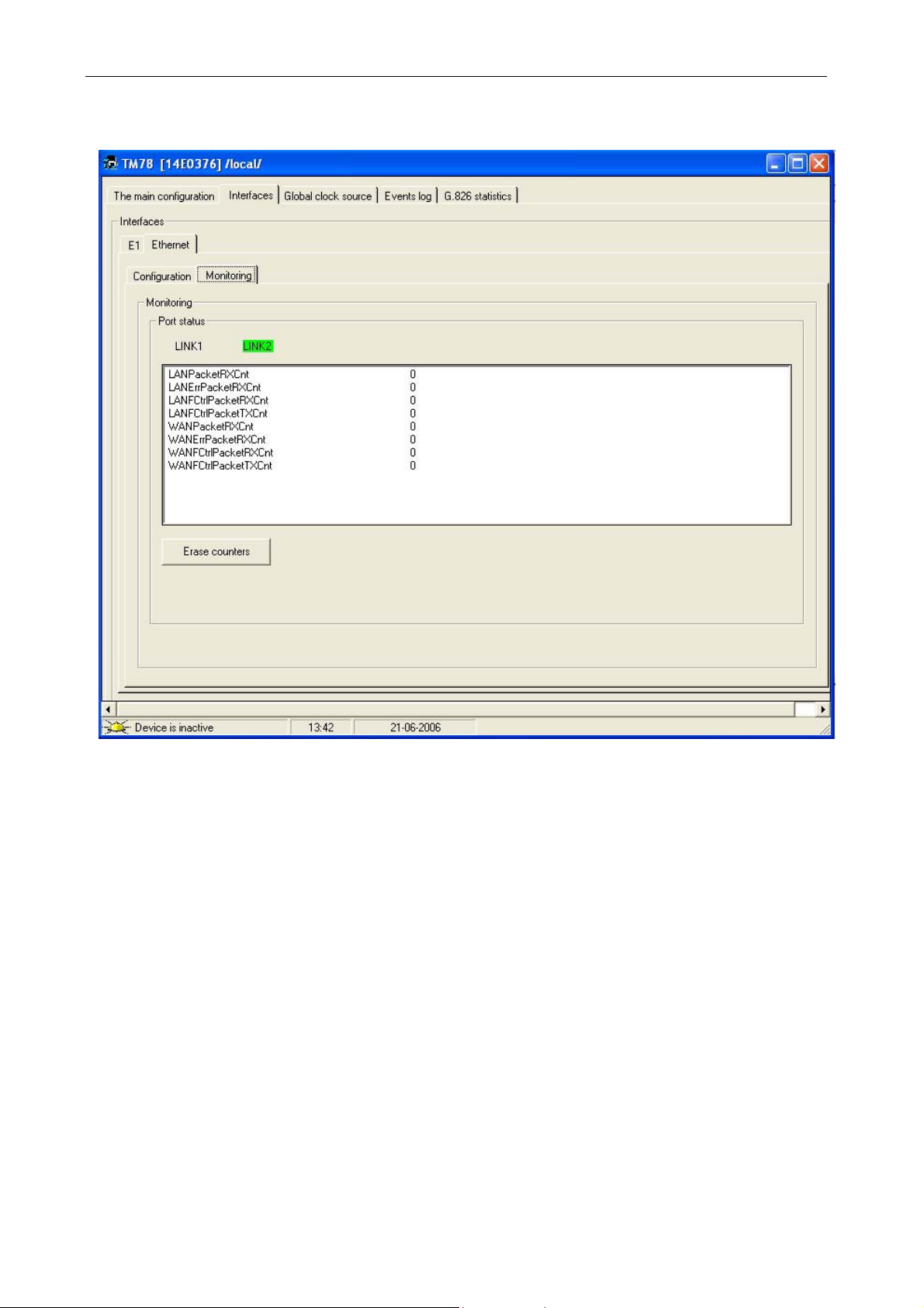
Figure 5-9: Interfaces - Ethernet, Monitoring.
In this tab, you can view the Ethernet interface signaling. The following parameters are
monitored:
LINK1 – loss of signal on port 1
LINK2 – loss of signal on port 2
LANPacketRXCnt – number of packets received from the Ethernet interface
LANErrPacketRXCnt – number of errored packets received from the Ethernet interface
LANFCtrlPacketRXCnt – number of flow-controlled packets received from the Ethernet
interface
LANFCtrlPacketTXCnt – number of flow-controlled packets transmitted to the Ethernet
interface
WANPacketRXCnt – number of packets received from E1
WANErrPacketRXCnt – number of errored packets received from E1
WANFCtrlPacketRXCnt – number of flow-controlled packets received from the E1 interface
WANFCtrlPacketTXCnt – number of flow-controlled packets transmitted to the E1 interface
_______________________________________________________________________________
IOA78-1C 22 January 2005
Page 28
10Base-T/100Base-TX/E1 converter
5.3. Global clock
Operating Manual
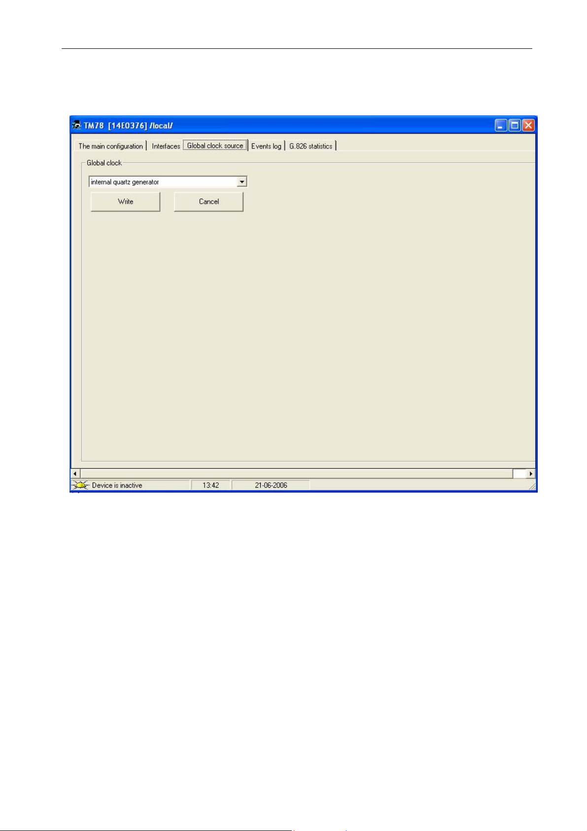
Figure 5-10: Global clock.
In this tab you can select clock source for data transmitted in the direction of E1/G.703 line
interface. The clock can be selected from two sources:
• from internal quartz generator, frequency 2.048 MHz ±50 ppm, operating in MASTER
mode
• from clock retrieval systems of opposite direction of transmission E1/G.703, operating in
SLAVE mode
_______________________________________________________________________________
IOA78-1C 23 January 2005
Page 29
10Base-T/100Base-TX/E1 converter
5.4. Log
5.4.1. Event log tab
Operating Manual
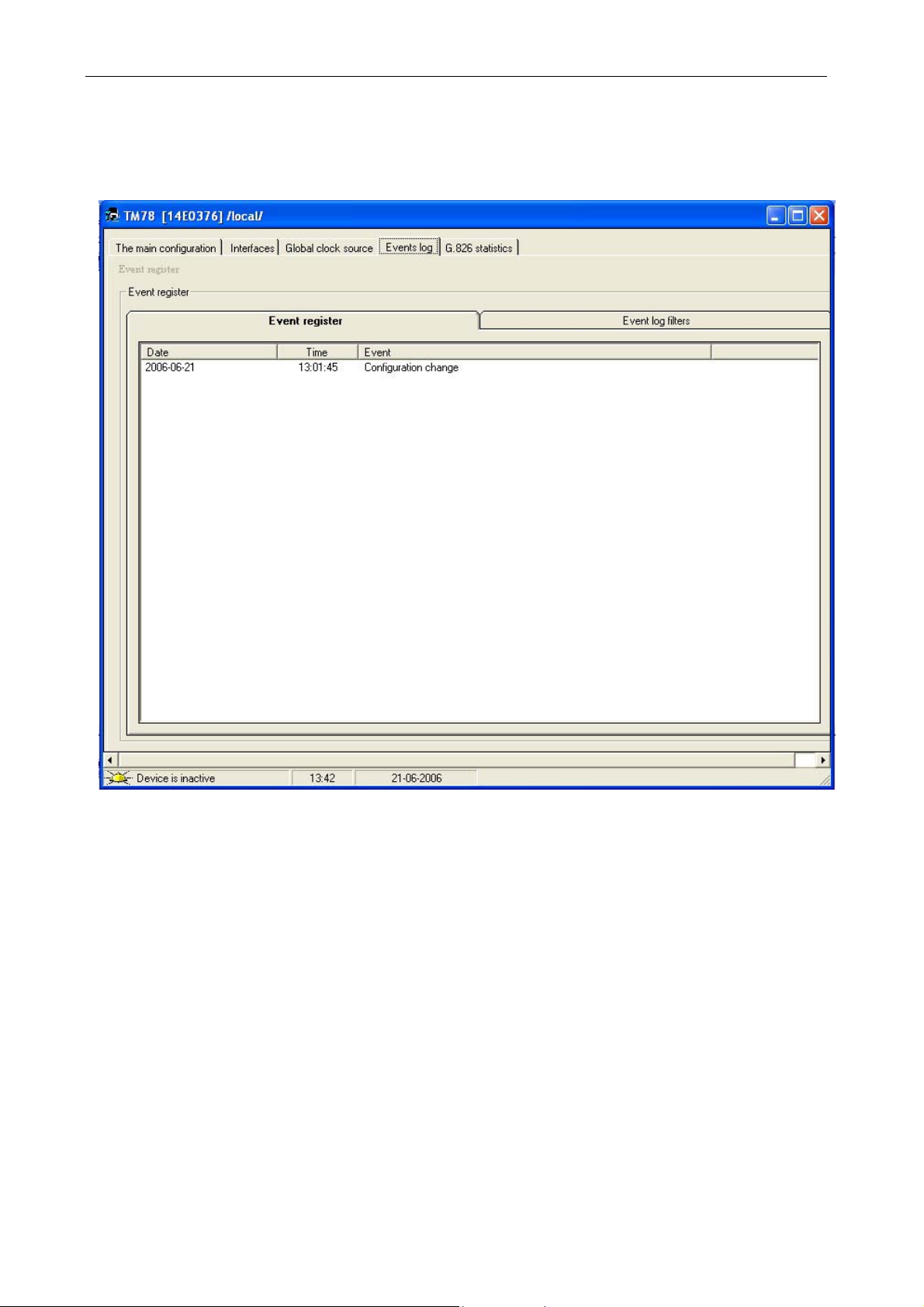
Figure 5-11: Log - Event log.
Event log tab displays recorded events related to the converter. The types of recorded
The
events are described in section 0. You can delete the whole recorded list of events in this tab. To
do that, right-click this window and select
Clearing log.
_______________________________________________________________________________
IOA78-1C 24 January 2005
Page 30
10Base-T/100Base-TX/E1 converter
5.4.2. Event log tab, event log filters
Operating Manual
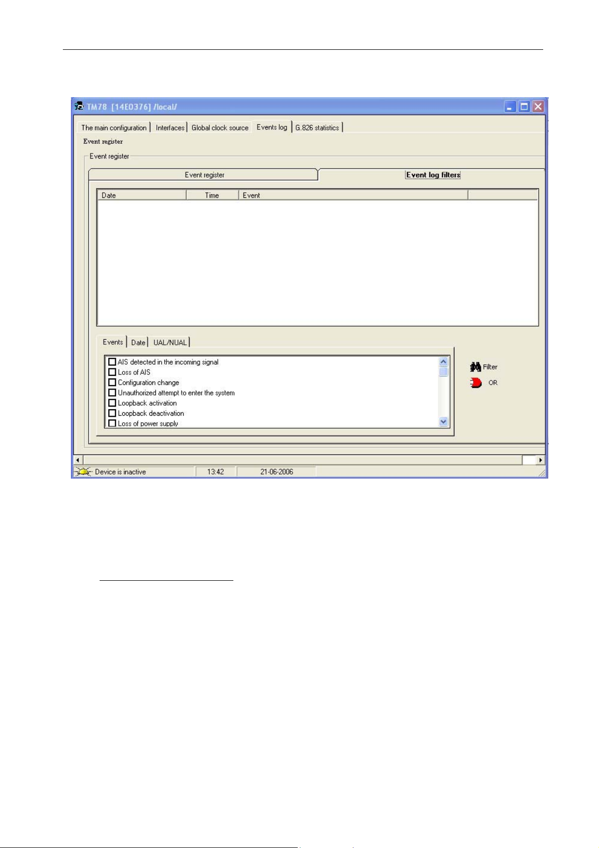
Figure 5-12: Log - Event log filters.
This tab is divided into two parts. The upper section of the tab displays events filtered out
from all recorded events (which are displayed in the
Event log tab).
The bottom left of the window shows three subtabs. You can use them to select events
filtering criteria.
List of filtering criteria tabs
Events - Here you can choose to display events of only one type from the above list of recorded
events (Figure 5-12).
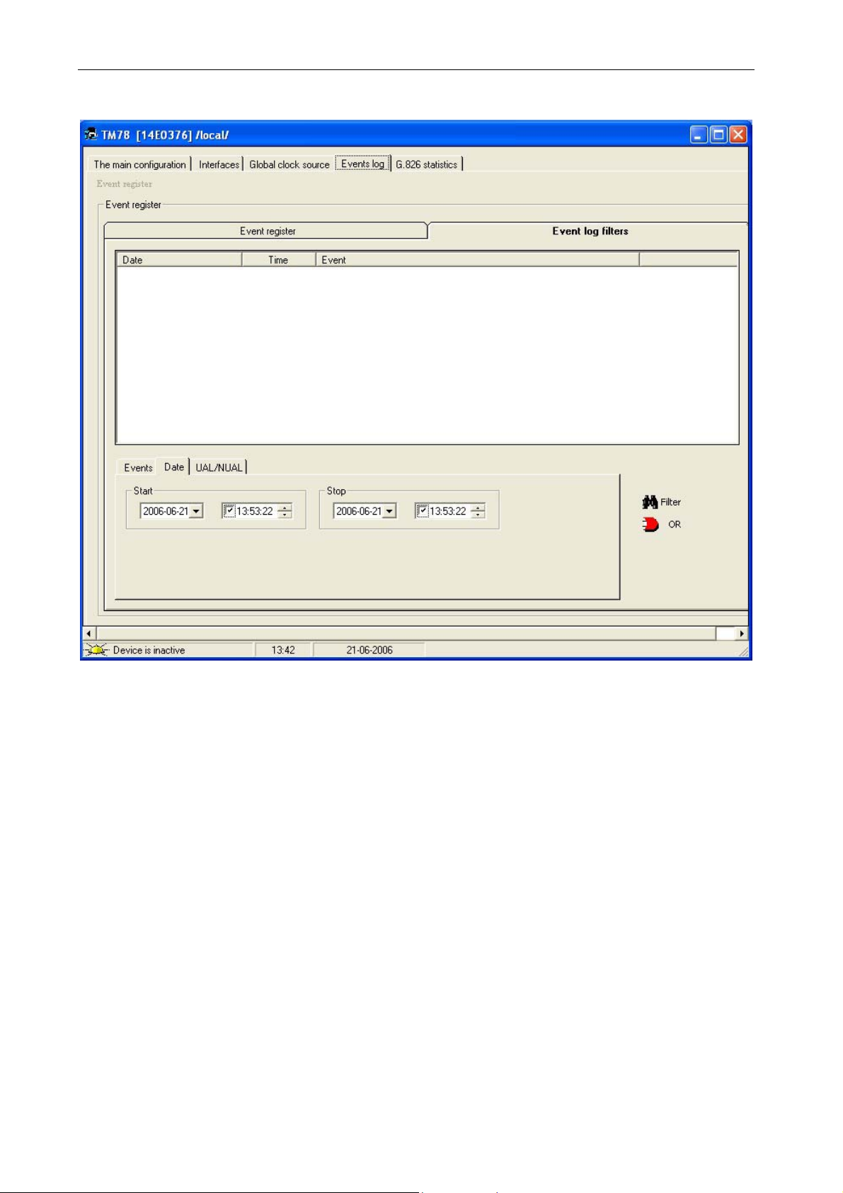
Date – Here you can select events filtering time criterion. In this tab, beginning and end date and
time of this criterion can be selected (Figure 5-13).
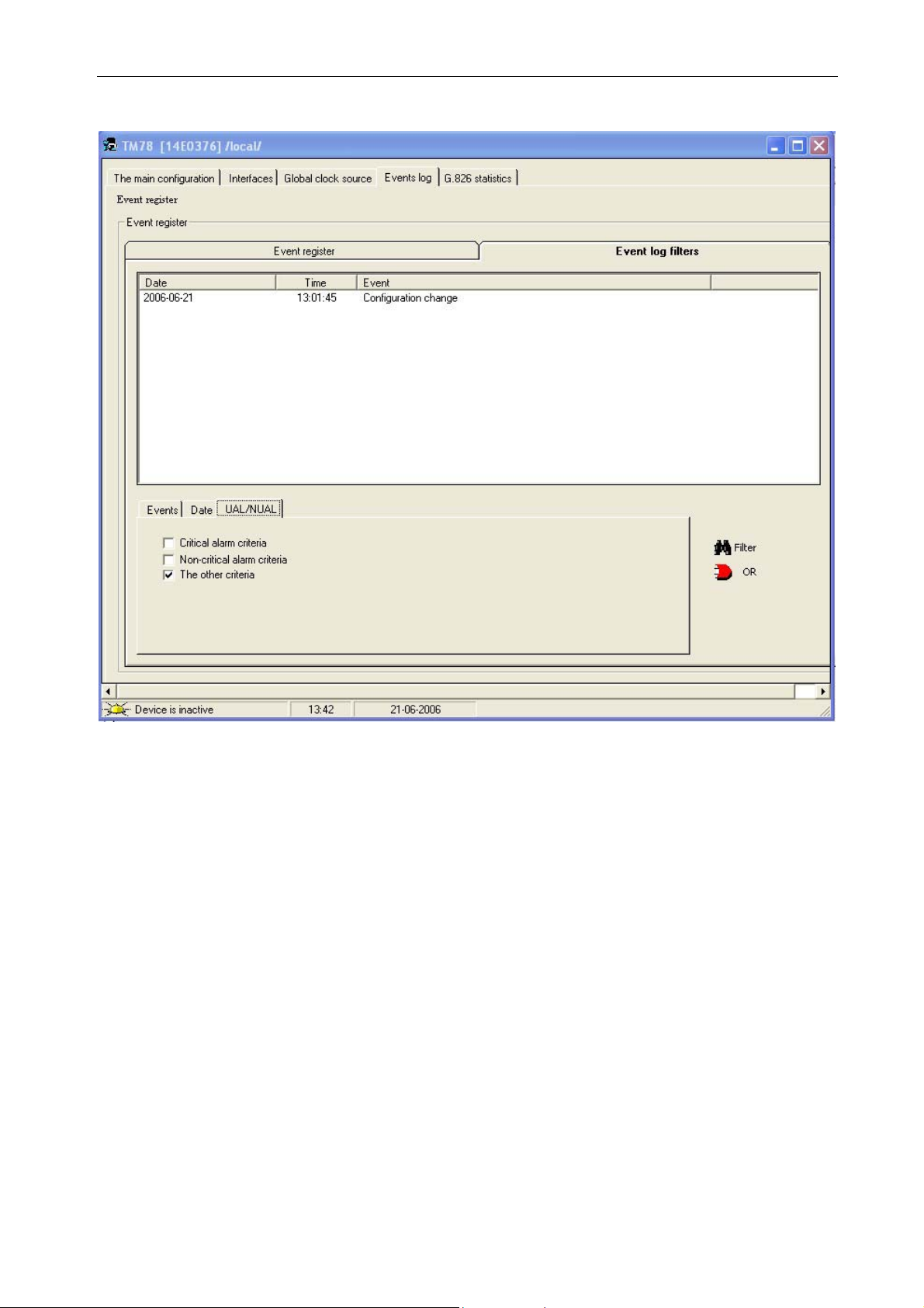
UAL/NUAL – Here you can select the criteria of displayed events, same as the ones determined
for:
• Urgent alarm criteria (Figure 5-14)
• Non-urgent alarm criteria (Figure 5-14)
• other criteria (not contained in the urgent and non-urgent alarm criteria.)
Two buttons are located on the right side of this window:
Filter – displays events of the same type and value as in the left-hand tab.
OR – displays events applying criteria from all tabs
_______________________________________________________________________________
IOA78-1C 25 January 2005
Page 31
10Base-T/100Base-TX/E1 converter
Operating Manual
Figure 5-13. Event log filter – Date.
_______________________________________________________________________________
IOA78-1C 26 January 2005
Page 32
10Base-T/100Base-TX/E1 converter
Operating Manual
Figure 5-14. Event log filter – UAL/NUAL.
_______________________________________________________________________________
IOA78-1C 27 January 2005
Page 33

10Base-T/100Base-TX/E1 converter
Operating Manual
5.5. G.826 statistics
In this tab, you can set start time for counting:
• of errored seconds - ES
• of severely errored seconds - SES
• of errored blocks – EB
• of device unavailability seconds - UAS,
You can also set the minimum and maximum threshold values for SES15, SES24, ES15,
ES24 counters, on the basis of which event log entries and alarms are generated. Generating
threshold exceeded alarms can be switched on or off.
5.5.1. G.826 statistics, Counters tab.
When you press the Menu key in the upper left corner of the tab, a drop-down list is
displayed with the following commands:
Reports
Save
Print
Clear (clearing ES/SES counters),
Count initialization time (a new window opens for entering the time),
Generating UAL and NUAL
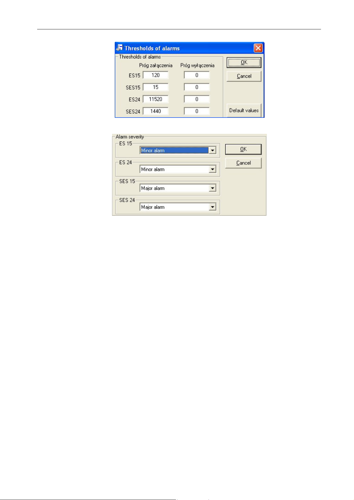
Setup (a window opens for entering threshold values of switching the signaling of
ES15, SES15, ES24, SES24 errors).
You can also enter the count starting time, pressing the
Count initialization time button to
the right of the ES/SES window, or clicking the box below this button. Setting up threshold values
of switching the signaling of ES15, SES15, ES24, SES24 errors is also possible after clicking
anywhere on the ES/SES window. Pressing the
Generating UAL and NUAL button enables
signaling these alarms after the set ES/SES threshold values have been exceeded.
Depending on which button you press:
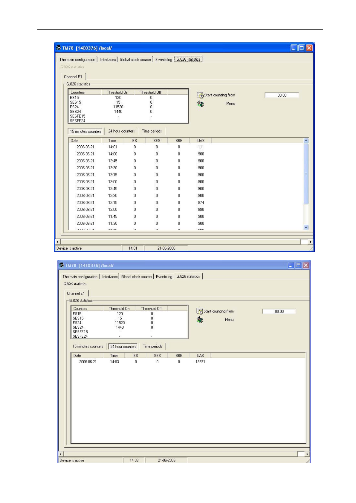
15-minute counters, or 24-hour counters, the
bottom section of this tab will display (Figure 5-15, Figure 5-16):
• number of errored seconds - ES
• number of severely errored seconds - SES
• number of errored blocks – BBE
• number of device unavailability seconds - UAS,
When you press
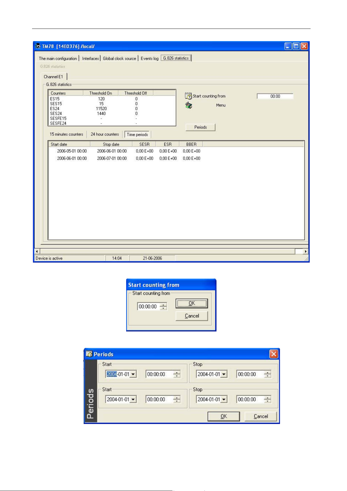
Time periods, the following will be displayed (Figure 5-17):
• proportion of errored seconds to all seconds when the device is available – ESR [%]
• proportion of severely errored seconds to all seconds when the device is available – SESR [%]
• proportion of errored blocks to all blocks when the device is available – BBER [%]
Ranges button appearing in this window enables entering time periods in which
The
measurement is performed (Figure 5-19).
_______________________________________________________________________________
IOA78-1C 28 January 2005
Page 34
10Base-T/100Base-TX/E1 converter
Operating Manual
Figure 5-15. G.826 statistics – 15-minute counters.
Figure 5-16. G.826 statistics – 24-hour counters.
_______________________________________________________________________________
IOA78-1C 29 January 2005
Page 35
10Base-T/100Base-TX/E1 converter
Operating Manual
Figure 5-17. G.826 statistics – Time periods.
Figure 5-18. Count initialization time.
Figure 5-19. Ranges.
_______________________________________________________________________________
IOA78-1C 30 January 2005
Page 36
10Base-T/100Base-TX/E1 converter
Figure 5-20. Alarm on thresholds.
Operating Manual
Figure 5-21. Alarms hierarchy.
_______________________________________________________________________________
IOA78-1C 31 January 2005
Page 37

10Base-T/100Base-TX/E1 converter
Operating Manual
6. TECHNICAL SPECIFICATION
6.1. Electrical characteristics
6.1.1. Ethernet interface
Parameter Value of the parameter
Standard describing the electrical interface IEEE 802.3
10Base-T transmission rate 10 Mbit/s, full duplex and half duplex
100Base-TX transmission rate 100 Mbit/s, full duplex and half duplex
Input and output impedance
10Base-T line code Manchester
100Base-TX line code MLT-3
Length of segment 100m
Required cabling Category 5 UTP or STP
Error rate
Type of connection RJ-45
100
≤10
Ω
-8
6.1.2. E1/G.703 line interface
Parameter Value of the parameter
Standard describing the electrical interface ITU-T G.703
Transmission rate in line
2048 kbit/s
±50 ppm
Data transmission rate n x 64kbit/s, n=1 do 31, zgodnie z G.704
Input and output impedance
Maximum cable transmission loss for frequency
1024kHz
Ω
120
43 dB
Line code HDB-3
Error rate
≤10
-9
Type of connection RJ-45
6.2. Mechanical parameters
Parameter Value
Width 105 mm
Height 36 mm
Depth 185 mm
Weight 0.6 kg
_______________________________________________________________________________
IOA78-1C 32 January 2005
Page 38

10Base-T/100Base-TX/E1 converter
Operating Manual
6.3. Environmental requirements
6.3.1. Operation
The converter may operate indoors, in unevenly heated rooms, in the following ambient
conditions:
Environmental parameter Acceptable value
Ambient temperature
Air relative humidity
+5
≤ 80% at a temperature of +20
÷ +40
O
C
O
C
6.3.2. Transport
The devices in factory packaging should be transported in the following conditions:
Environmental parameter Acceptable value
Ambient temperature
Temperature variation rate
-25
≤ 10
÷ +40
O
C/h
O
C
Maximum air humidity 95%
Atmospheric pressure
Multiple strokes
÷ 1060 hPa
700
÷ 15 g in 10 ms
5
6.3.3. Storage
Converters should be stored indoors, in the following ambient conditions:
Environmental parameter Acceptable value
Ambient temperature
-25
÷ +55
O
C
Humidity 5% to 90% over +40OC
Vibrations
frequency: 10 Hz to 55 Hz, amplitude: 0.15 mm
duration: 10 cycles in three planes
Level of pollution typical home or office environment
6.4. Electromagnetic compatibility
Converters conform to requirements for A class devices regarding radio/electrical interference
as set out in the PN-EN 55022 standard,
provided that they have been installed in accordance with
this manual.
Warning:
This is a Class A device. In a domestic environment this product may cause radio and electrical interference
in which case the user may be required to take adequate measures.
6.5. Power Supply
Parameter Value
Rated supply voltage
÷5,5 V; 0 Hz
4,5
Maximum rated power input 800 mA
Type of connection double clamped (screwed) joint
_______________________________________________________________________________
IOA78-1C 33 January 2005
Page 39

10Base-T/100Base-TX/E1 converter
Operating Manual
7. PRODUCT ELEMENTS AND ACCESSORIES
The complete packing list of the product delivered to the customer includes:
EtherTel TM-78 converter
1.
2. RS-232 cable, DB-9 RJ-45 pins. 1 pcs.
3. Operating manual 1 pcs.
4. Guarantee card 1 pcs.
Recommended power supply units:
1. 230 VAC Mascot type 5015, 4,5 VDC, 1,2A
2. 48 VDC Merawex type ECD1-R2- 48s05,
two-core cable 2x0.75mm, length 1 m
3M band, length 0.15m
1 pcs.
_______________________________________________________________________________
IOA78-1C 34 January 2005
Page 40

10Base-T/100Base-TX/E1 converter
Operating Manual
_______________________________________________________________________________
IOA78-1C 35 January 2005
Page 41

10Base-T/100Base-TX/E1 converter
Manufacturer:
Lanex S.A.
8 Ceramiczna Street
20-150 Lublin POLAND
phone: +48 81 444-10-11
fax: +48 81 740-35-70
e-mail: [email protected]
web: www.lanex.pl
Service contact:
phone +48 81 443 96 39
Lanex S.A. 2005
Operating Manual
_______________________________________________________________________________
IOA78-1C 36 January 2005
 Loading...