

Landwin C-arm X-ray Service Manual

Mobile C-arm X-ray System Service Manual
Important! … X-Ray Protection
Please strictly observe the protective measures; otherwise the X-ray
equipment shall hurt the patients and the operators.
The X-ray equipment shall cause the injury in the event of improperly operation.
Therefore, please read the instructions carefully and fully understand them before
the equipment is brought into service. We are willing to help and coordinate with
you to put the equipment into service.
Although the equipment produced on the basis of the strict safety standards can
provide the effective protection of X-ray radiation and the useful beamline protection,
actually, no equipment can provide the complete protection, and further more, no
equipment can force the operators to take the adequate protective measures to prevent
oneself or other people from being exposed in the X-ray radiation due to the negligence,
rashness and involuntary of the operators.
Importantly, all operators who operate the X-ray equipment should be properly
trained, and the proper protective measures should be applied to avoid the hurt. The
manufacturers consider that all operators and maintainers who are authorized to use,
install, regulate and maintain the equipment have already known the hazard of the
immoderate exposure in the X-ray and received the sufficient training and grasped the
related knowledge. The manufacturers, agents and sales representatives are not
responsible for any injury and damage caused by exposure in the X-ray.
All kinds of protective materials and equipments can be obtained in market and the
clients are proposed to use these kinds of materials and equipments.
i

Mobile C-arm X-ray System Service Manual
Environment Explanation
Service Period of Equipment or System
The equipment or the system comprises the harmful components and materials
(such as PCB, electronic modules, wasted insulating oil, lead and battery etc.) which
can pollute the environment. Above-mentioned components and materials become
harmful when the life cycle of the equipment or system comes to the end.
Above-mentioned components and materials are considered to be harmful waste
material in accordance with the international law, domestic regulation and local
regulation.
The manufacturers propose to contact the authorized waste management
companies to deal with these equipments or systems when the life cycle of the
equipment or the system comes to the end.
Manufactured by
Shenzhen Landwind Industry Co., Ltd.
Address: 4F, Block E, Bijing Bldg. 81, Jingtian Road, Futian District, Shenzhen China.
Tel: +86-755-27353247
Fax: +86-755-27353240
Email: Int.service@landwind.com.cn
ii

Mobile C-arm X-ray System Service Manual
All rights reserved.
This Manual and the information contained herein are proprietary information of
Shenzhen Landwind Industry Co., Ltd. No information or any part hereof can be copied,
reproduced, compiled, modified, distributed or transmitted, in any form or by any means,
without the prior written consent of Shenzhen Landwind Industry Co., Ltd. This Manual is
intended for
users who are authorized to use such Manual as a part of the product purchased from
Landwind. Use of this Manual by unauthorized personnel is strictly forbidden.
Shenzhen Landwind Industry Co., Ltd. makes no representations or warranties of any
kind concerning the document, express or implied, including, without limitation,
warranties of merchantability and fitness for a particular purpose. Although every effort
has been exerted to ensure the accuracy of the information contained herein, Shenzhen
Landwind Industry Co., Ltd. assumes no liabilities for any errors or omissions and
reserves the right to modify the product to improve its reliability, function or design
without further notice. Shenzhen Landwind Industry Co., Ltd. may modify or improve the
product or program described herein at any time.
The product may contain recycled parts whose performance is equivalent to brand-new
parts or rarely used parts.
Is the trademark of Shenzhen Landwind Industry Co., Ltd. Other product
names may be trademarks of their respective owners.
iii

Mobile C-arm X-ray System Service Manual
Revision Record of Version
Revision numbers Date Revision Reasons
A0 Sep, 6 , 2010 Firstly edition
iv

Mobile C-arm X-ray System Service Manual
ADVISORY SYMBOLS
The following advisory symbols will be used throughout this manual .Their
application and meanings are described below. Users shall be familiar with these
symbols and meanings thereof before operation of the equipment.
Danger: it will cause the serious injuries or even death if people do not pay
attention to or not avoid this state or condition.
Warning: it will cause the serious injuries or heavy loss of equipment or data if
people do not pay attention to or not avoid this state or condition.
Caution: it will cause the injuries or loss of equipment or data if people do not
pay attention to or not avoid this state or condition.
Note: Remind the reader of the relative fact and condition. The notice items
show the important information which should be known but has not
necessary relationship with possible personal injury or damage of the
equipment.
Different configurations are available according to demands of user. In the event of
discrepancy between the actual and this edition, the actual configuration shall prevail.
Contact to the manufacture or the provider if there is any unsolvable problems of the
equipment.
v

Mobile C-arm X-ray System Service Manual
SAFETY SYMBOLS
The following safety symbols will be used in the equipment .Their meaning are
described below.
Attention! Consulting the document accompanying
with the machine
Ionizing radiation
Dock C-arm Inward before transport
Pinch Warning
X-ray radiation
B-type equipment
Dangerous voltage
Ground
vi
This symbol indicates that the waste of electrical and
electronic equipment must not be disposed as
unsorted municipal waste and must be collected
separately. Please contact an authorized
representative of the manufacturer or an authorized
waste management company for information
concerning the decommissioning of your equipment.

Mobile C-arm X-ray System Service Manual
Table of Contents
Chapter 1 Overview .......................................................................................................... 1
1.1 Main Components...............................................................................................................1
1.2 Console Panel......................................................................................................................2
1.3 C-Arm & Frame..................................................................................................................3
1.4 T echnique Specification......................................................................................................4
Chapter 2 Tools and test equipment.................................................................................. 9
2.1 T ools for installation ...........................................................................................................9
2.2 T ools for maintenance.........................................................................................................9
Chapter 3 Installation instruction......................................................................................11
3.1 Field requirement..............................................................................................................11
3.2 Running environment........................................................................................................12
3.3 Unpacking and Inspection.................................................................................................12
3.4 Installation.........................................................................................................................13
3.4.1 Mechanical Movement and Brake Function Test...........................................13
3.4.2 Install image intensifier ......................................................................................14
3.4.3 Installation of tube assembly ............................................................................17
3.4.4 Installation of circuit board ................................................................................19
3.4.5 Wiring of image intensifier and tube head ......................................................24
3.4.6 Installation of image intensifier cover ..............................................................26
3.4.7 Wiring of Unit.......................................................................................................27
Chapter 4 Debugging ...................................................................................................... 29
4.1 Debugging of main board voltage.....................................................................................29
4.2 Aligning the Combined Tube with Image Intensifier........................................................31
4.3 Center debugging of CCD camera....................................................................................31
4.4 The debugging of Resolution............................................................................................33
4.5 Tube seasoning..................................................................................................................34
Chapter 5 Acceptance test.............................................................................................. 35
5.1 Appearance inspection ......................................................................................................35
5.1.1 Appearance of Complete Machine and Its Parts ...........................................35
5.1.2 Components of Tube Head...............................................................................36
5.1.3 Image Intensifier .................................................................................................36
5.1.4 Operation Panel..................................................................................................36
5.2 Cable Connection Inspection............................................................................................36
5.3 Mechanical Inspection ......................................................................................................37
I

Mobile C-arm X-ray System Service Manual
5.4 Electrical Inspection..........................................................................................................37
5.5 Function inspection...........................................................................................................38
Chapter 6 Maintenance................................................................................................... 41
6.1 Precautions and Prohibitions.............................................................................................41
6.2 Cautions with X-Ray tube head ........................................................................................42
6.3 Periodic Routine Maintenance..........................................................................................44
6.4. Cleaning and Disinfection................................................................................................44
6.5 Troubleshooting ................................................................................................................45
6.5.1 Common faults analysis ....................................................................................45
6.5.2 Check of Main Circuit Board .............................................................................48
6.5.3 Other Troubleshooting .......................................................................................53
Chapter 7 Spare parts................................................................................................... 57
7.1 Whole machine..................................................................................................................57
7.2 Control cabinet..................................................................................................................58
7.3 High frequency inverter ....................................................................................................60
7.4 Rotating anode control module.........................................................................................61
7.5 Tube head..........................................................................................................................62
7.6 Image intensifier ...............................................................................................................63
7.7 TV System.........................................................................................................................65
7.8 Other .................................................................................................................................65
Appendix........................................................................................................................ 69
Schematics....................................................................................................................85
II

Mobile C-arm X-ray System Service Manual
Chapter 1 Overview
1.1 Main Components
The system comprises C-arm& Frame, control Cabinet, combined tube and image
intensifier, TV system (Image storage device, 14” monitor,14” Display and TV System
handcar).
3) C-Arm & Frame 4) Image Intensifier 5) TV System
1) Control Cabinet 2) Tube Head
Appearance of whole machine
1

Mobile C-arm X-ray System Service Manual
1.2 Console Panel
Console Panel
1 C-Arm Vertical Travel: ▲Up/▼Down 2 Power ON/OFF: ON⊙
3
Power ON/OFF: 〇 OFF
4 Emergency stop switch
5 Console LCD Panel 6 Settings
Target Parts (Target anatomical
7
parts from left to right: Head, Chest,
8 Type of patient: thin
Waist, Buttock, Knees, Hands)
9 Type of patient :Moderate 10 Type of patient :Large
11 Front/Lateral 12 Read/Write
13 Radiography 14 Manual Fluoroscopy
15 Automatic Fluoroscopy 16 Pulse Fluoroscopy
17 Enhance Fluoroscopy 18 Intensifier Diameters
19 Timer Reset 20 IRIS Collimator Shutter Open/Close
21 Two-Blade Collimator Shutter 22
2
Two-blade Collimator Left/Right

Mobile C-arm X-ray System Service Manual
Open/Close Rotation
X-Ray: Yellow indicator will light
23
when X-Ray is active. 24
READY: Green indicator will light
when the equipment is ready after
the Manual Switch 1 is pressed
FAULT: Red indicator will light only when over-loading or malfunction. X-Ray is in
25
inactive state. The Console LCD Panel displays “Fil fault” or “Rota fault” or “Fault”
1.3 C-Arm & Frame
C-Arm orbital motion, vertical travel, panning, horizontal travel, and pivot rotation can
all be manually controlled.
C-Arm & Frame
1) C-Arm Orbital Motion Lock/Unlock 2) C-Arm Panning Lock/Unlock
3

Mobile C-arm X-ray System Service Manual
3) C-Arm Pivot Rotation Lock/Unlock 4) C-Arm Horizontal Travel Lock./Unlock
5) Control Handle/Shutdown
6) Control Handle/Steering/brake lever
1.4 Technique Specification
X-Ray Generator
Max. Fluoroscopy Capacity
Max. Radiography Capacity 1s@40kV/ 80mA/1s
Fluoroscopy Current Range
Radiological Current Range Discrete: 80mA@40kV; 20mA@120kV
3h non-continuous operations@75kV/1mA
Continuous
0.2~4.0mA@ step 0.1mA
Fluoroscopy
Enhance Fluoroscopy
4.0~8.0mA@ step 0.1mA
Tube Voltage Range and
Tolerance
Radiography mAs Range
Maximum Output tube current
with Nominal tube Voltage
Maximum tube voltage with
maximum tube current
Fluoroscopy & Radiography: 40~120kV, Tolerance ≤
10%
1~180mAs; discrete; Tolerance ≤ 10%
Continuous Fluoroscopy
Pulse Fluoroscopy
Radiography
Continuous Fluoroscopy
Pulse Fluoroscopy
Radiography
120 kV,4 mA
120 kV,8mA
120 kV,30 mA
4.0mA,120 kV
8.0mA,120 kV
70 mA,49kV
Maximum Output Power
4
Continuous Fluoroscopy 120 kV×4.0mA=0.48
kW

X-ray tube
Mobile C-arm X-ray System Service Manual
Pulse Fluoroscopy 120 kV×8.0mA=0.96
kW
Radiography 59 kV×60 mA=3.54
kW
Nominal Power 100 kV×30mA=3.0 kW (0.1s)
Power 5kW
Anode Rotating anode
Focus 0.3mm/0.6mm
Heat capacity
800KHU(600KJ)
Collimator
Adjust electrical adjustable
Smallest X-ray field (@1m SID): L x W ≤ 5cm x 5cm.
Power 12V/70 mA;
Structure IRIS Lead Shutter: One pair lead blades,;
Image Intensifier
adjustable intensifier diameters 9", 6", 4.5" three view
C-Arm & Frame
Vertical Travel
400mm±2mm(electrical)
Horizontal Travel 200mm±5mm
Pivot Rotation ±180°
5

Mobile C-arm X-ray System Service Manual
Panning Motion ±12.5°
SID 900mm
Slide along arc
C-arm arc 650mm
CCD Camera
Sensitivity 0.0003LUX
SNR ≥45 dB
X-Ray TV System/Image storage device
Image Acquisition LIH: Last Image Hold
Image Resolution Horizontal Center: the level centre≥12
-25°~0~100°
LP/cm
Noise ≤70dB (Under no-load condition, maximum
noise level)
Image Grayscales ≥ 8 levels
Acquire rate 10bit
Monitor resolution 768×576
Storage frame
8+1
Monitor 14"
Display 14"
Other parameters
Power Source Single phase
Sinusoidal AC
6

Mobile C-arm X-ray System Service Manual
Power Supplies
Frequency 50Hz
Capacity ≥5kVA
Voltage Source 220V±10%
Internal Impedance ≤ 0.6Ω
Cassette holder 240mm×300mm
Tube Voltage (kV), Tube Current (mA), mAs, Output Power reference table.
kV mA mAs kW
110~100
99~80
79~70
69~60
59~50
49~40
20
30
40
40
50
60
1~80 2.40~2.00
1~125 2.97~2.40
1~125 3.16~2.80
1~125 2.76~2.40
1~125 2.95~2.50
1~125 2.94~2.40
7

Mobile C-arm X-ray System Service Manual
This page is intentionally left blank.
8

Chapter 2 Tools and test equipment
2.1 Tools for installation
NO. Name QTY
Multimeter
1
electric iron 、soldering tin
2
Inner-hexagon wrench
3
Mobile C-arm X-ray System Service Manual
1
1
1 set
Cross screwdriver (L,M,S)
4
Slotted screwdriver
5
Long nose plier
6
oblique clamp mouth
7
crimp wire pliers (crimp Pre-insulated
8
pipe-type head)
2.2 Tools for maintenance
1 set
1
1
1
1
NO. Name Type Units QTY
1 live wrench 8 inch Pcs 1
9

Mobile C-arm X-ray System Service Manual
2 inner Hexagon wrench metric set 1
3 philips screwdriver (L,M,S) set 1
4 slotted screwdriver (L,M,S) set 1
5 multimeter General Pcs 1
6 electrical iron STANLEY 69-033C Pcs 1
7 oblique clamp mouth STANLEY 84-009 Pcs 1
crimp wire pliers (crimp
8
Pre-insulated pipe-type
Pcs 1
head)
crimp wire pliers(crimp
9
Pre-Insulated fork-type
Pcs 1
head )
10 electrical tape 3M, wide 12mm roll 1
11 wire stripping pliers STANLEY 84-318 Pcs 1
12 solder Ф0.8mm roll 1
13 solid wrench M8 Pcs 1
14 needle nose pliers STANLEY 84-007 Pcs 1
15 Resolution test card Pcs 1
10

Mobile C-arm X-ray System Service Manual
Chapter 3 Installation instruction
This equipment can only be installed and tested by the manufacturer or other
personnel authorized by the manufacturer.
3.1 Field requirement
Field area should not be less than 50 ㎡ in principle. The room, with the narrowest
location not less than 4m, should be divided into operating room and control room, and
lead protective measures should be accordance with local requirement. For this
equipment is a mobile Unit, the ground should be leveled without doorsill at the joint
between rooms to facilitate free access of the equipment through the door with a width of
90cm..
The power supply required by the overall system is single phase AC with frequency
of 50Hz±1Hz, capacity no less than 3.5kW. Ask for 16A three-core inlet, rated voltage of
220V±10% and source resistance not higher than 0.6Ω. The power supply should be
grounded securely with earth resistance not higher than 4Ω. (Criteria for ground wire: a
metal rod buried to a depth of 1m underground with salt and carbon powder sprinkled
around and tamped.)
If the power level is at 220V with no X-Ray emission and drops more than 3V (for
example, if Tube V/A at 70KV/3mA) with X-Ray emission, this indicates that the power
source doesn’t supply sufficient power and a 5kW or above AC voltage stabilizer needs to
be installed (should be equipped with a reliable brand).
Supply the equipment with an independent power source is mandatory since shared
power source might cause severe electromagnetic interferences impacting normal
performance of the X-Ray equipment.
11

Mobile C-arm X-ray System Service Manual
3.2 Running environment
Normal working condition Transportation and storage
Temperature 10ºC ~ +40ºC
Relative humidity ≤70%
Atmospheric
70kPa ~ 1060kPa
-40℃~55℃
10%~80%
3
50×10
~106×103Pa.
pressure
Voltage 220V±22 V /
Power 50Hz±1Hz /
Power capacity ≥ 5kVA /
Internal Impedance ≤ 0.6Ω
Power plug ground wire must be connected to Earth ground.
Connect to temporary or low capacity power supply is strictly prohibited. Sharing
power source with other load bearing equipment (such as soldering machine etc.) is also
not recommended.
The equipment should be stored only at no-direct sunlight, dry, humidity-controlled and
well ventilated indoors. Direct contact with ground dirt should be strictly avoided.
Weather-resistant measures must be taken for temporary storage at all times.
3.3 Unpacking and Inspection
Unpack; check packed items according to the packing list. Make sure all parts are in
good condition. In case, there is any damage found, please contact the manufacturer
immediately for handling.
12

Mobile C-arm X-ray System Service Manual
Note: Use a box opener to unpack the upper case first and than the side covers at
last remove the fix objects.
z Check whether the accessories are complete and in perfect conditions after
unpacking.
z Please contact your supplier immediately if any accessory is incomplete or
damaged.
z The list of accessories depends on your purchase contract.
Note: Please reserve the packaging material for future reuse in transporting the
instrument.
The installation must be performed in accordance with technical data. Upon
completion of installation, make sure all protection ground wires provided by the
manufacturer are securely connected and protective covers are installed and fixed with
screws before turning on the power of the equipment.
3.4 Installation
3.4.1 Mechanical Movement and Brake Function Test
1. Push the equipment to check for its flexibility and smoothness of movement. Ensuring
it can be tightly locked. Run test on its movements to ensure there is no block in glide of
C-arm along arc, 200m range of forward/backward movement, 12.5° range of left/right
sway, rotation around horizontal axis, etc.
2. Braking mechanism: firstly open the rear cover of X-ray unit, wrap terminal L and N
with insulation tape to avoid occurrence of short circuit between terminals or between
terminal and floor, shown as follows:
13

Mobile C-arm X-ray System Service Manual
3. Connect power supply (220V AC) with the power line, press “Power ON” button and
then press “Brake” button as shown in the following figure. Now the equipment is braked
automatically. Confirm whether the equipment is braked completely by pushing it gently.
And switch off power and remove power line.
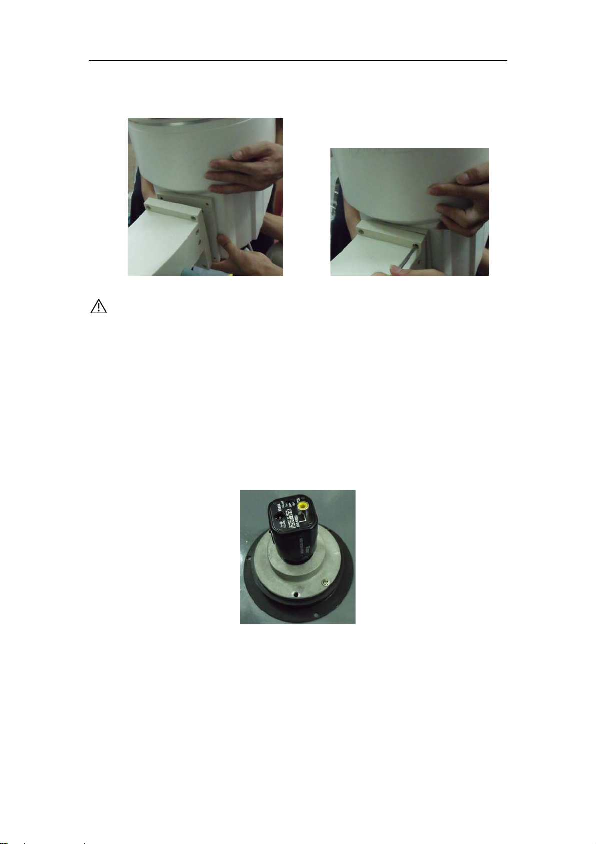
3.4.2 Install image intensifier
1. Release the handrails for C-arm circular arc movement, adjust C-arm to proper
position for convenient installation of image intensifier and then lock the locking handrails
again.
2. Take out image intensifier from package box and check whether there is any
appearance damage. Remove the six pieces of mounting screws supplied with image
intensifier connecting plate by using inner hexagon wrench, as shown in the following
figure.
Mounting screw
Connecting plate
3. Align the connecting holes to the ones on the connecting plate on image intensifier end
14
Mobile C-arm X-ray System Service Manual
of C-arm, and fix them with mounting screws supplied with the equipment.
Note: At least two persons are needed to avoid personal injury or device damage
caused by the drop of image intensifier
Keep the edge of connecting plate parallel to the one of mounting plate to assure
precision of image intensifier. mounting position.
4. Take out CCD camera from the package box, and detach the cover base to take CCD
camera out.
5. Remove the blue plastic dust-proof cover for output screen from the bottom of image
intensifier, and check whether there is dust on the output screen. Blow away the dust with
blowing balloon if any. The cleanness within this region is extremely important as the
image intensifier output screen is the focal plane for imaging.
15

Mobile C-arm X-ray System Service Manual
p
Dust-proof cover for
out
ut screen
6. Remove lens cover of camera, align mounting holes of camera to the ones at the
bottom of image intensifier and fix with three pieces of screws.
Note: Rotate both CCD and image intensifier clockwise until an included angle is
presented up to 90°for installation and fixing.
Screws to fix camera
7. Align the cover base to the mounting holes at the bottom of image intensifier and fix it
with three pieces of screws.
Fixing screws
16

Mobile C-arm X-ray System Service Manual
3.4.3 Installation of tube assembly
1 Unpack the case of the tube assembly, take out the tube head.
2. Remove the flat washers, spring washers and mounting nuts from tube head. One
person is to hold the tube head and align the X-ray output window to the mounting hole of
L-shaped steel plate, install with the washers and fix the tube by tightening the nuts.
Note: Since the equipment before shipment has been marked with marking pen as to
the accurate mounting positions on L-shaped steel plate. And during the flat washers
were needed to facilitate the installation.
X-ray output window
Mounting washes and nuts
3. Connect the fan cable of tube head with the corresponding cable on C-arm as follows:
17

Mobile C-arm X-ray System Service Manual
4. Install collimator. Loosen the three pieces of screws on the collimator cover with
slotted screwdriver and detach the collimator cover;
5. Loosen the three pieces of jack screws at the bottom of collimator, align collimator to
the x-ray output window, put it in the mounting groove of tube output window, position the
collimator right through fine adjustment, and fix the collimator with jack screws tightened
by inner hexagon wrench.
18

Mobile C-arm X-ray System Service Manual
3.4.4 Installation of circuit board
The circuit boards were detached form the circuit board frame to facilitate the transport
and Unit safety. So on-site installation need to re-install the circuit board.
1. Remove screws on the wheel cover to detach the wheel cover: detach the two pieces
of screws on the rear cover of equipment to remove the rear cover of equipment.
2. Remove the fixed screws of frame and push the frame outward. At this juncture the
white nylon clips that are used for fixing the main control board on the four corners of
core component can be seen.
3. Take out main control board from the package box, align it to the mounting holes on
the four corners with connection side of green terminal upward and ribbon cable terminal
downward, and fix it on the frame.
19

Mobile C-arm X-ray System Service Manual
4. Plug in CP1—CP11 (except CP8) to the corresponding connection-peg one by one.
5. Power on the Unit to check if the voltage of CP8 is normal. The referring data shown
as follows:
CP8.1 CP8.2 CP8.3 CP8.4 CP8.5 CP8.6 CP8.7 CP8.8
0V 5V 12V 0V 24V 15V 0V 15V
Those voltages come from the three pieces of switching power supply beside the frame.
If the voltage from certain group is abnormal, check if the corresponding switch is
powered and if the wirings are connected properly.
6. Switch off the unit if the voltages above are measured normal. Connect CP8 terminal
line to CP8 terminal block and measure the voltage of measurement point on main
control board after power on again. At the same time, measure to confirm whether the
voltages of CP1 power terminal line and CP2 terminal line which is connected to filament
20

Mobile C-arm X-ray System Service Manual
board are correct. Refer to following table for measurement points and the related
reference data are shown below:
Set mA Set kV U15-3 CP1.1-CP1.3 CP2.
CP2.2 CP2.3
1
3.5-3.7V 2V 8.5V 135VAC±10% +15V 0V -15V
Relevant Voltage Measurement Points
Adjust the RP mA potentiometer if the Set mA voltage is abnormal; Adjust the RP kV
potentiometer if the Set kV voltage is abnormal; Adjust R50 potentiometer if U15-3
voltage is abnormal.
21

Mobile C-arm X-ray System Service Manual
7.Switch off the power of the equipment. Unpack the filament power board SCH S15 and
fix it to the white nylon clips on the right side of main body.
8. Connect the terminals on board S15.
9. Take the inverter out of the package box.
22
 Loading...