

Page 1

OPERATING MANUAL
Page 2

OMBG3000 – Iss.A
© Copyright 2016 –
Page 3

© Copyright 2016
OMBG3000 – Rev1
Table of Contents
Manual guidelines ................................................................................. 9 1
1.1 Safety symbol ........................................................................................ 9
1.2 Hyperlinks .............................................................................................. 9
1.3 Notes ..................................................................................................... 9
Safety information .............................................................................. 10 2
2.1 Safety instructions ............................................................................... 10
2.2 ATEX and IECEx Certification ............................................................... 12
Marking ............................................................................................... 12 2.2.1
Instructions Specific to Hazardous Area Installations .......................... 13 2.2.2
Entity Parameters ................................................................................ 15 2.2.3
2.3 Range of environmental conditions .................................................... 15
2.4 Safety symbols used on the instrument .............................................. 16
BIOGAS 3000 Overview ....................................................................... 17 3
3.1 Features ............................................................................................... 17
3.2 Benefits ................................................................................................ 18
3.3 Options ................................................................................................ 19
3.4 Main Applications ................................................................................ 19
3.5 Model Type Definitions ....................................................................... 20
BG3K1 .................................................................................................. 20 3.5.1
BG3K2 .................................................................................................. 20 3.5.2
BG3K3 .................................................................................................. 21 3.5.3
BG3K4 .................................................................................................. 22 3.5.4
BG3KD .................................................................................................. 23 3.5.5
3.6 BIOGAS 3000 Internal Components ..................................................... 25
3.7 BIOGAS 3000 Module Features ........................................................... 27
BG3KE .................................................................................................. 23 3.5.6
Page 4

OMBG3000 – Iss.01
© Copyright 2016
Physical Characteristics of the Module ................................................ 27 3.7.1
Definitions ........................................................................................... 29 3.7.2
Installation .......................................................................................... 31 4
4.1 Pre-Installation Requirements ............................................................. 31
General ................................................................................................ 31 4.1.1
Packaging Contents ............................................................................. 32 4.1.2
Storage of the System and Module ..................................................... 32 4.1.3
Ventilation Requirements .................................................................... 33 4.1.4
4.2 External Customer Connections .......................................................... 33
4.3 Mounting the Enclosure ...................................................................... 34
4.4 Connecting the Gas Lines to the BIOGAS 3000 .................................... 36
Gas Sample Lines ................................................................................. 36 4.4.1
Process Return ..................................................................................... 37 4.4.2
Air In .................................................................................................... 38 4.4.3
Vent to Atmosphere ............................................................................ 38 4.4.4
4.5 Drain .................................................................................................... 38
4.6 Protective Cover .................................................................................. 41
4.7 Cable Gland Selection and Cord Anchorage ........................................ 42
4.8 Cable Conductor Sizes and Insulation Requirements .......................... 44
Cable Conductor Sizes ......................................................................... 44 4.8.1
Cable Insulation Requirements ............................................................ 44 4.8.2
4.9 Mains Wiring ....................................................................................... 45
Protective Earthing and Mains Supply ................................................. 45
4.9.1
How to Wire the Mains Supply ............................................................ 46 4.9.2
4.10 Modbus Digital Output ........................................................................ 48
Wiring the BIOGAS 3000 Modbus Outputs .......................................... 48 4.10.1
Default Configuration of the BIOGAS 3000 Modbus Port .................... 50 4.10.2
Readable Parameters of the BIOGAS 3000 .......................................... 50 4.10.3
Page 5

© Copyright 2016
OMBG3000 – Rev1
4.11 4-20mA Outputs .................................................................................. 57
General Information ............................................................................ 57 4.11.1
Wiring the BIOGAS 3000 to a Current Sinking Input ............................ 58 4.11.2
4-20mA Scaling .................................................................................... 60 4.11.3
4.12 Relays .................................................................................................. 61
4.13 Profibus Digital Output ........................................................................ 63
Configuration of the Profibus Module ................................................. 63 4.13.1
Wiring the Profibus Module ................................................................ 65 4.13.2
Readable Parameters of the Profibus Module .................................... 68 4.13.3
4.14 Profinet Digital Output ........................................................................ 72
Configuration of the Profinet Module ................................................. 72 4.14.1
Wiring the Profinet Module ................................................................. 73 4.14.2
Readable Parameters of the Profinet Module ..................................... 76 4.14.3
4.15 Heater Option ...................................................................................... 79
4.16 Final Checks ......................................................................................... 80
General Operating Instructions ........................................................... 81 5
5.1 Switching the BIOGAS 3000 System On ............................................... 81
5.2 Self-Test ............................................................................................... 81
5.3 First Time Run Set-up .......................................................................... 83
5.4 Gas Readings Screen ............................................................................ 85
5.5 Alarms .................................................................................................. 88
Notification .......................................................................................... 88 5.5.1
Viewing Alarms .................................................................................... 89
5.5.2
5.6 Stop Sampling ...................................................................................... 90
5.7 Menu ................................................................................................... 91
Settings Menu ...................................................................................... 92 5.7.1
Device Information Menu .................................................................. 108 5.7.2
Calibration Menu ............................................................................... 112 5.7.3
Page 6

OMBG3000 – Iss.01
© Copyright 2016
5.8 Help Function .................................................................................... 117
5.9 BIOGAS 3000 Sampling Process ......................................................... 118
BG3K1, 2, 3, 4, and D Variants ........................................................... 118 5.9.1
BG3KE Variants .................................................................................. 119 5.9.2
5.10 Switching the BIOGAS 3000 System Off ............................................ 120
Gas Check and Calibration ................................................................. 121 6
6.1 Introduction ....................................................................................... 121
6.2 Required Equipment .......................................................................... 122
Gas ..................................................................................................... 122 6.2.1
Flow Regulator ................................................................................... 122 6.2.2
6.3 Gas Mixtures ...................................................................................... 123
Adding a Mixture ............................................................................... 124 6.3.1
Deleting a Mix .................................................................................... 125 6.3.2
Edit O
in Fresh Air Mix ...................................................................... 126 6.3.3
2
6.4 Connecting a Gas Bottle to the BIOGAS 3000 .................................... 128
6.5 Gas Check and Calibration ................................................................. 131
6.6 Status Icons ....................................................................................... 133
Post Gas Check .................................................................................. 133 6.6.1
Post Calibration ................................................................................. 133 6.6.2
6.7 Disconnecting a Gas Bottle from the BIOGAS 3000 ........................... 134
Maintenance ..................................................................................... 136 7
7.1 Maintenance Schedule ...................................................................... 136
7.2 BIOGAS 3000 Consumable Products .................................................. 138
7.3 Emptying the Catchpot ...................................................................... 140
7.4 Replacing the Catchpot Filter ............................................................ 143
7.5 Replacing the Inline PTFE Filter ......................................................... 147
7.6 Pressure Test ..................................................................................... 150
Required Equipment .......................................................................... 150 7.6.1
Page 7

© Copyright 2016
OMBG3000 – Rev1
Diagnostics Control Mode ................................................................. 150 7.6.2
General Set-Up .................................................................................. 152 7.6.3
Performing the Pressure Test ............................................................ 152 7.6.4
7.7 Cleaning and Decontamination ......................................................... 158
Service .............................................................................................. 159 8
8.1 General .............................................................................................. 159
8.2 Service Notifications .......................................................................... 159
8.3 Replacement BIOGAS 3000 Module for Service – Hot Swap ............. 160
Problem Solving ................................................................................ 163 9
9.1 Fault Detection .................................................................................. 163
Non-Critical Faults ............................................................................. 163 9.1.1
Critical Faults ..................................................................................... 165 9.1.2
9.2 System Will Not Power On ................................................................ 166
9.3 Module Will Not Power On ............................................................... 166
9.4 Module Lock-Up ................................................................................ 167
9.5 Under and Over Range Codes ............................................................ 167
9.6 Analog Outputs Not Working ............................................................ 168
9.7 Modbus Outputs Not Working .......................................................... 168
9.8 Low Flow / Flow Fail .......................................................................... 168
9.9 Fuses .................................................................................................. 169
9.10 User Calibration Explained ................................................................ 170
General .............................................................................................. 170 9.10.1
9.10.2
Factory Calibration ............................................................................ 171
User Zero Calibration ......................................................................... 171 9.10.3
9.11 CH4 Reading Low and O2 Reading High .............................................. 174
9.12 Event Log ........................................................................................... 174
User Span Calibration ........................................................................ 172 9.10.4
Trouble Shooting ............................................................................... 172 9.10.5
Page 8

OMBG3000 – Iss.01
© Copyright 2016
BIOGAS 3000 Warranty Terms and Conditions .................................. 176 10
WEEE Compliance .............................................................................. 179 11
Declaration of Conformity .......................... Error! Bookmark not defined. 12
Glossary of Terms .............................................................................. 180 13
Page 9
Operating Manual
Manual guidelines
9
© Copyright 2016
OMBG3000 – Rev1
Warning
Warning text will be placed here.
Manual guidelines
1
1.1 Safety symbol
Information in this manual that may affect the safety of users and others is in
the following format:
Failure to follow this information may result in physical injury that in some
cases could be fatal, cause damage to the equipment or to the environment, or
invalidate the certification of the equipment.
1.2 Hyperlinks
Hyperlinks to other sections of this manual, websites or email addresses are in
the following format:
www.landtecna.com
1.3 Notes
Important/useful information and instructions are shown clearly throughout
the manual in a note format.
For example:
Note: For further information contact our technical support team at (800)
968-2026 or email [email protected].
Page 10

10
Operating Manual
Safety information
OMBG3000 – Iss.01
© Copyright 2016
Warning
The BIOGAS 3000 comes with a guard that covers all
accessible components with mains power. This guard
must only be removed when power to the system is
isolated. Failure to isolate the supply could result in an
electric shock.
When opening the cabinet great care must be taken by
the operator as mains voltages are present. It is the
responsibility of the owner of the equipment to ensure
that all personnel are adequately trained.
It is the responsibility of the owner of this equipment to
complete a risk assessment on its installation, operation,
and maintenance prior to it being used.
Anti-static precautions should be observed during
installation, maintenance, and general operation of the
equipment.
Inhaling toxic gases may be harmful to health and in
some cases may be fatal. It is the responsibility of the
user to ensure that he/she is adequately trained in the
safety aspects of the gases being used and appropriate
procedures are followed. In particular, where hazardous
gases are being used, the gas exhausted from the system
must be piped to an area where it is safe to discharge
the gas, or returned to the process.
The equipment should not be altered in any way other
than described within this operating manual. Alterations
or changes outside of this operating manual could make
the equipment unsafe and invalidate the ATEX/IECEx
certification.
It is vital that the instructions in this operating manual
are followed closely. Failure to comply could cause an
injury to the operator.
Safety information 2
2.1 Safety instructions
Page 11

Operating Manual
Safety information
11
© Copyright 2016
OMBG3000 – Rev1
The auto-drain pump will need replacing before 4,000
hours use. At 3,000 hours, a non-critical fault will appear
on screen to advise the user that replacement is due. At
4,000 hours, a critical fault will occur and stop the
system from operating until replaced.
Suitably trained personnel should carry out the installation in
accordance with the applicable code of practice.
Repair and maintenance of this equipment should be carried out in
accordance with the applicable code of practice and this operating
manual.
Only LANDTEC approved components are to be used as replacement
parts.
If the equipment is likely to be exposed to aggressive substances (e.g.
acidic liquids, gases that may attack metals or solvents that may affect
polymeric materials) then it is the responsibility of the user to take
suitable precautions, e.g. regular checks are performed as part of
routine inspections or establishing from the material’s datasheet that it
is resistant to specific chemicals.
Note: If there is any uncertainty, please contact our technical support
team at (800) 968-2026 or email [email protected].
Page 12
12
Operating Manual
Safety information
OMBG3000 – Iss.01
© Copyright 2016
Warning
The equipment is designed for use in potentially
explosive atmospheres as defined by the classification.
The equipment can be configured to measure low levels
of several gases, but may not be certified for use in
potentially explosive atmospheres of these gases. It is
the responsibility of the operator to determine the
protection concept and classification of equipment
required for a particular application and if these gases
create a potentially explosive atmosphere.
The equipment should not be altered in any way other
than described within this operating manual. Alterations
or changes outside of this operating manual will
invalidate the certification and could make the apparatus
unsafe.
2.2 ATEX and IECEx Certification
Marking 2.2.1
In reference to European ATEX Directive 2014/34/EU and the IECEx
International Certification Scheme, the BIOGAS 3000 has been certified
according to the following designation:
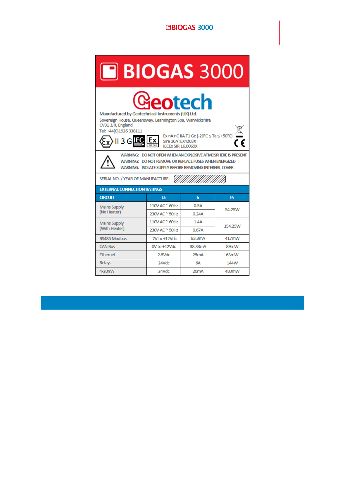
II 3G
Ex nA nC IIA T1 Gc (-20°C ≤ Ta ≤ +50°C)
Nameplate 1 - BIOGAS 3000 markings can be found on the main enclosure of
the system:
Page 13
Operating Manual
Safety information
13
© Copyright 2016
OMBG3000 – Rev1
Nameplate 1 - BIOGAS 3000 markings
Instructions Specific to Hazardous Area Installations 2.2.2
1) The equipment may be used in zones 2 with flammable gases and vapors
with apparatus groups IIA and with temperature classes T1.
2) The equipment is only certified for use in ambient temperatures in the
range -4ºF to +122ºF and should not be used outside this range.
3) Installation shall be carried out in accordance with the applicable code of
practice by suitably trained personnel.
4) There are no special checking or maintenance conditions other than a
periodic check.
5) With regard to explosion safety, it is not necessary to check for correct
operation.
Page 14

14
Operating Manual
Safety information
OMBG3000 – Iss.01
© Copyright 2016
6) The equipment contains no user-replaceable parts and is not intended to
be repaired by the user. Repair of the equipment is to be carried out by
the manufacturer, or their approved agents, in accordance with the
applicable code of practice.
Note: Please contact our technical support team at (800) 968-2026 or
email [email protected] to receive equipment repair
training.
7) Repair of this equipment shall be carried out in accordance with the
applicable code of practice.
8) If the equipment is likely to come into contact with aggressive substances,
e.g. acidic liquids or gases that may attack metals or solvents that may
affect polymeric materials, then it is the responsibility of the user to take
suitable precautions that prevent it from being adversely affected thus
ensuring that the type of protection is not compromised.
9) The certificate number has an ‘X’ suffix, which indicates that special
conditions of installation and use apply. Those installing or inspecting this
equipment must have access to the contents of the certificate or these
instructions. The conditions listed in the certificate are reproduced below:
All cable entry holes shall be fitted with either a certified cable gland or
a certified stopping plug with minimum IP65 that is suitable for the
application.
The equipment may only be used in areas with a low risk of mechanical
impact.
Warning – in locations where high external humidity and internal
temperature variations (e.g. frequent on-off cycles) may cause
condensation inside the equipment, the interior should be periodically
inspected.
The terminal blocks shall only be fitted with wires that have cross
sectional area falling within the terminal blocks certificates limitations.
Refer to operating manual.
Page 15
Operating Manual
Safety information
15
© Copyright 2016
OMBG3000 – Rev1
Circuit
Ur (rated voltage)
Ir (rated current)
Pr (rated power)
Relay coil
24Vdc
6A
144W
4-20mA
24Vdc
20mA
480mW
RS485 Modbus
-7 to +12V
83.3mA
417mW
Equipment has only been assessed for electrical safety. No non-
electrical assessment has been conducted and the manufacturer
declares compliance for this under his own responsibility.
10) Cell replacement must only be carried out in the safe area or when a
hazardous atmosphere is not present.
Note: Additional instructions shall be supplied alongside any
replacement cell related to the specific installation requirements.
11) Regarding the use of covers, jumpers, and end brackets, the instructions
of the manufacturer must be followed.
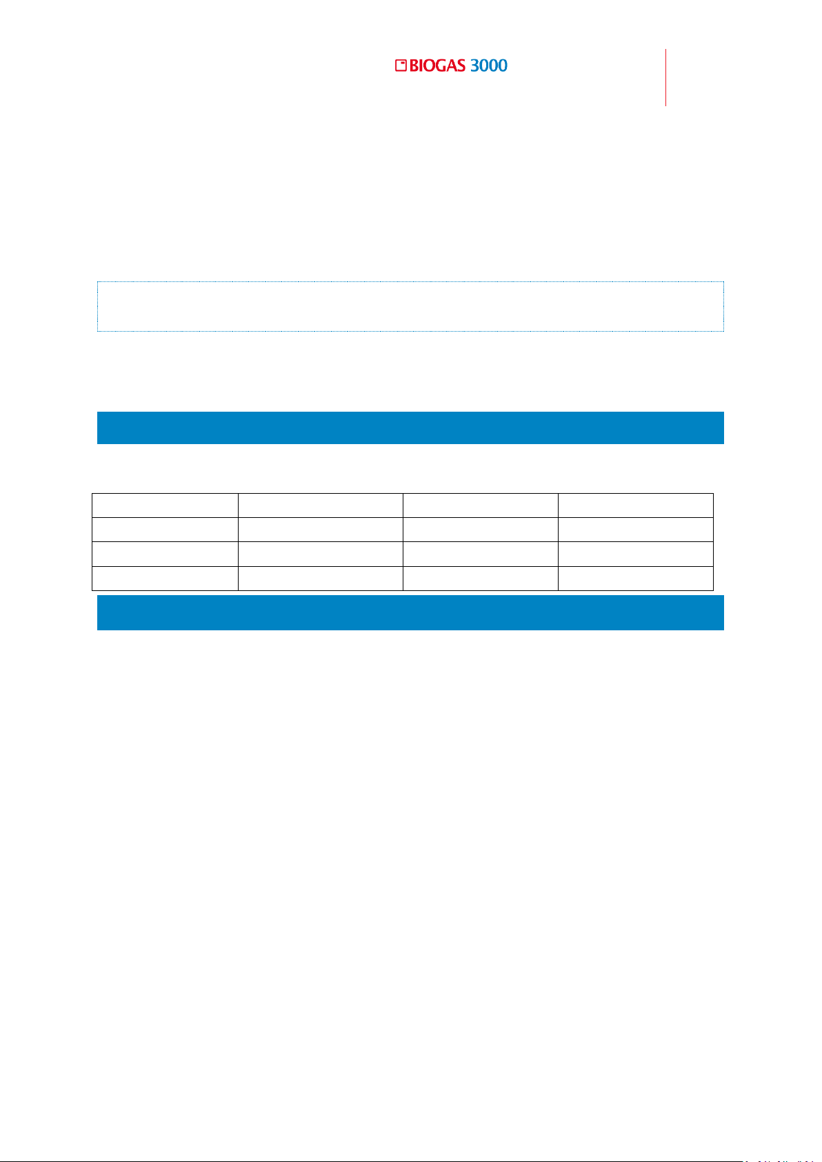
Entity Parameters 2.2.3
The following ratings must not be exceeded on the listed circuits below:
2.3 Range of environmental conditions
The system is only for use in ambient temperatures in the range of 0°C
to 50°C (32⁰F to 122⁰F) without the use of the approved heater, and 20°C to 50°C (-4⁰F to 122⁰F) with the use of the approved heater.
The BIOGAS 3000 is designed for use outdoors and has an IP65 rating.
The mains voltages (110-230V) can fluctuate up to ±10% of the nominal
voltage.
The system is only for use in ambient pressures in the range 700 to
1200mbar (-4.5 -2.7 psi).
Page 16
16
Operating Manual
Safety information
OMBG3000 – Iss.01
© Copyright 2016
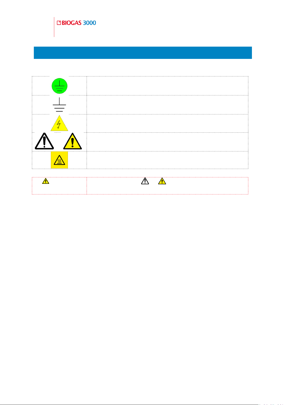
Protective conductor terminal
Function earth (ground) terminal
Caution, risk of electric shock
or
Caution
Caution, risk of hot surface
Warning
Where the symbol or is used in the BIOGAS 3000,
the operating manual must be consulted.
2.4 Safety symbols used on the instrument
The following safety symbols are used on the BIOGAS 3000:
Page 17
Operating Manual
BIOGAS 3000 Overview
17
© Copyright 2016
OMBG3000 – Rev1
BIOGAS 3000 Overview 3
3.1 Features
The BIOGAS 3000, primarily for the AD Biogas and Bio-methane upgrading
market has been designed to enable site operations to maximize gas
production yield and protect expensive capital equipment from the damaging
contaminant gases contained within the production process. The ATEX and
IECEx certified BIOGAS 3000 builds on field proven, robust gas analysis
technology to offer cost effective online monitoring with local data outputs.
CH
H
, CO2 & O2 – standard measurements
4
S, H2 and CO – optional measurements (choice of up to two)
2
Modular design enabling hot-swap for serviceability and onsite
maintenance
User calibration function to maintain accuracy and ensure data
reliability in extreme temperatures
ATEX and IECEx certified for use in potentially explosive gas
atmospheres – Zone 2
ISO/IEC 17025 calibration for optimal accuracy
Ability to monitor the gas control process before and after
desulphurization
Page 18

18
Operating Manual
BIOGAS 3000 Overview
OMBG3000 – Iss.01
© Copyright 2016
Continuous monitoring option
Up to 4 sample points to monitor the complete gas control process
Gas return to process as standard
IP65 rated for weatherproofing
Built-in liquid level monitoring with a dedicated alarm to inform the
user contents of the catchpot require emptying or an optional
automated moisture removal drain
Gas alarms and fault notifications
6 x 4-20mA outputs
Modbus RTU communication
Optional Profibus and Profinet communication
Clear, visual and informative color display
Optional heater to extend operating temperature range to -4°F
Extended Warranty and Service pack options through approved global
service centers
3.2 Benefits
Customizable to site requirements
Zero operational downtime for servicing
Product reliability and longevity
Protect expensive capital equipment from damaging gases
Maximize operational efficiency through optimizing the AD process
Operational within hazardous areas
Ease of operation, integration and installation
Page 19

Operating Manual
BIOGAS 3000 Overview
19
© Copyright 2016
OMBG3000 – Rev1
Minimal through-life costs
Local support for peace of mind
3.3 Options
H
S ranges from 0-50ppm to 0-10,000ppm
2
CO 0-1,000ppm
H
0-1,000ppm
2
Profibus replaces Modbus
Profinet replaces Modbus
110V or 230V heater
Auto-drain to empty contents of catchpot without user interaction
Hydrolysis tank measurement option to improve the life of the external
sensor, if required
3.4 Main Applications
AD research
Agricultural waste AD (large scale)
Biogas upgrading
Farm waste AD (small scale)
Gas flaring
Mixed food waste AD
Sewage / waste water treatment AD
Page 20
20
Operating Manual
BIOGAS 3000 Overview
OMBG3000 – Iss.01
© Copyright 2016
3.5 Model Type Definitions
BG3K1 3.5.1
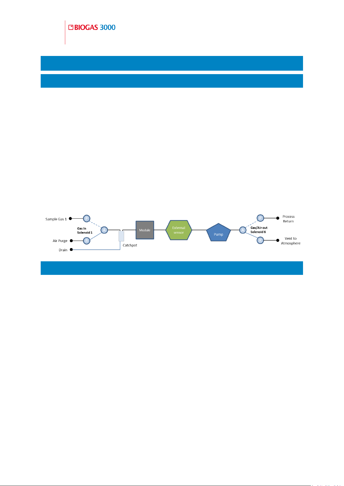
The BG3K1 measures CH
, CO2, and O2 as standard with a choice of up
4
to two additional gases (one internal to the module and one external)
and measures from one sample point.
It has user selectable sample and air purge intervals that are exhausted
back to the process and atmosphere respectively.
The 4-20mA and Modbus outputs are updated at the end of each
sample.
The following image is a simple block diagram of the system including
the optional external gas sensor:
BG3K2 3.5.2
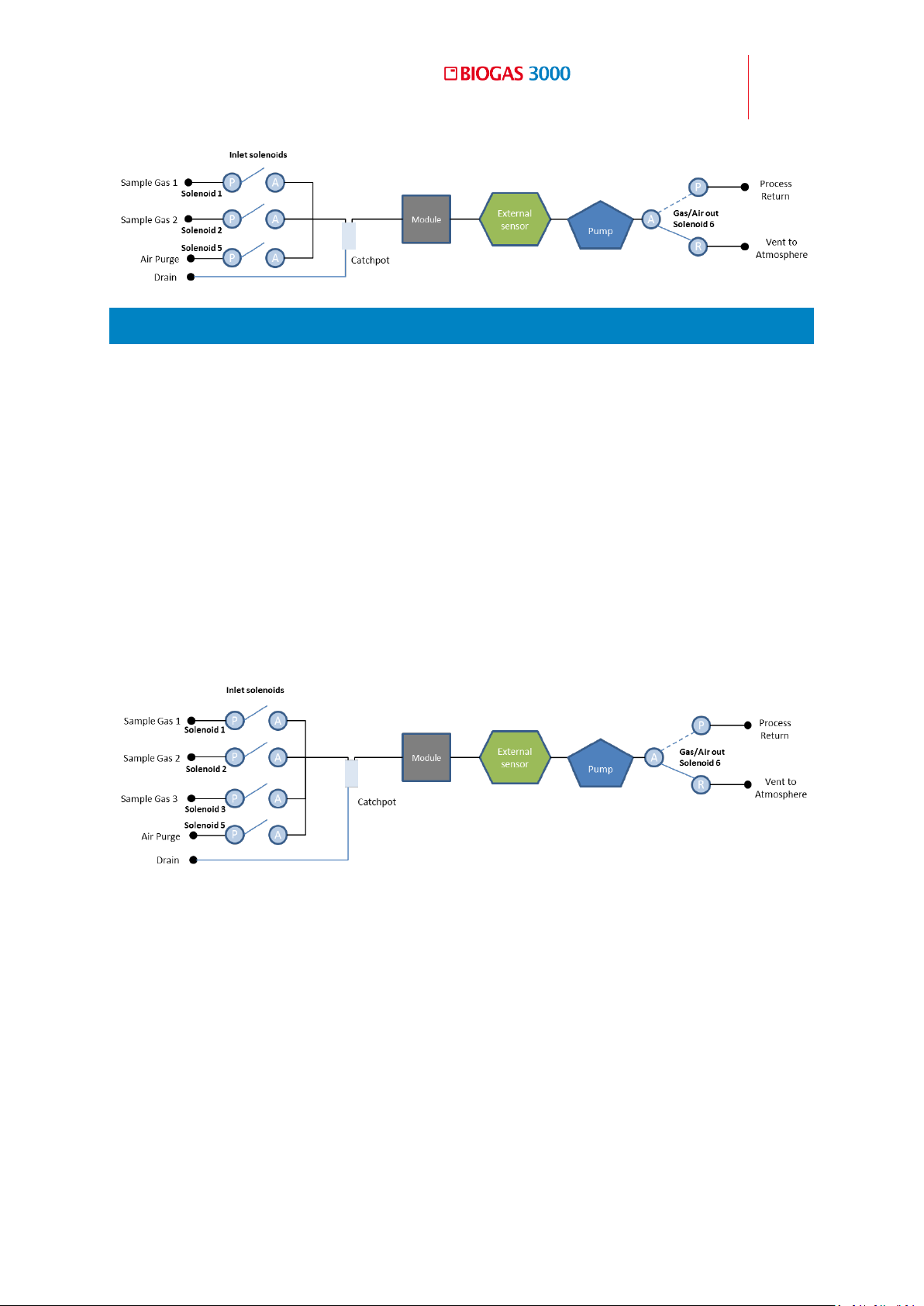
The BG3K2 measures CH
, CO2, and O2 as standard with a choice of up
4
to two additional gases (one internal to the module and one external)
and measures from two sample points.
It has user selectable sample and air purge intervals that are exhausted
back to the process and atmosphere respectively.
The 4-20mA and Modbus outputs are updated at the end of each
sample.
The following image is a simple block diagram of the system including
the optional external gas sensor:
Page 21
Operating Manual
BIOGAS 3000 Overview
21
© Copyright 2016
OMBG3000 – Rev1
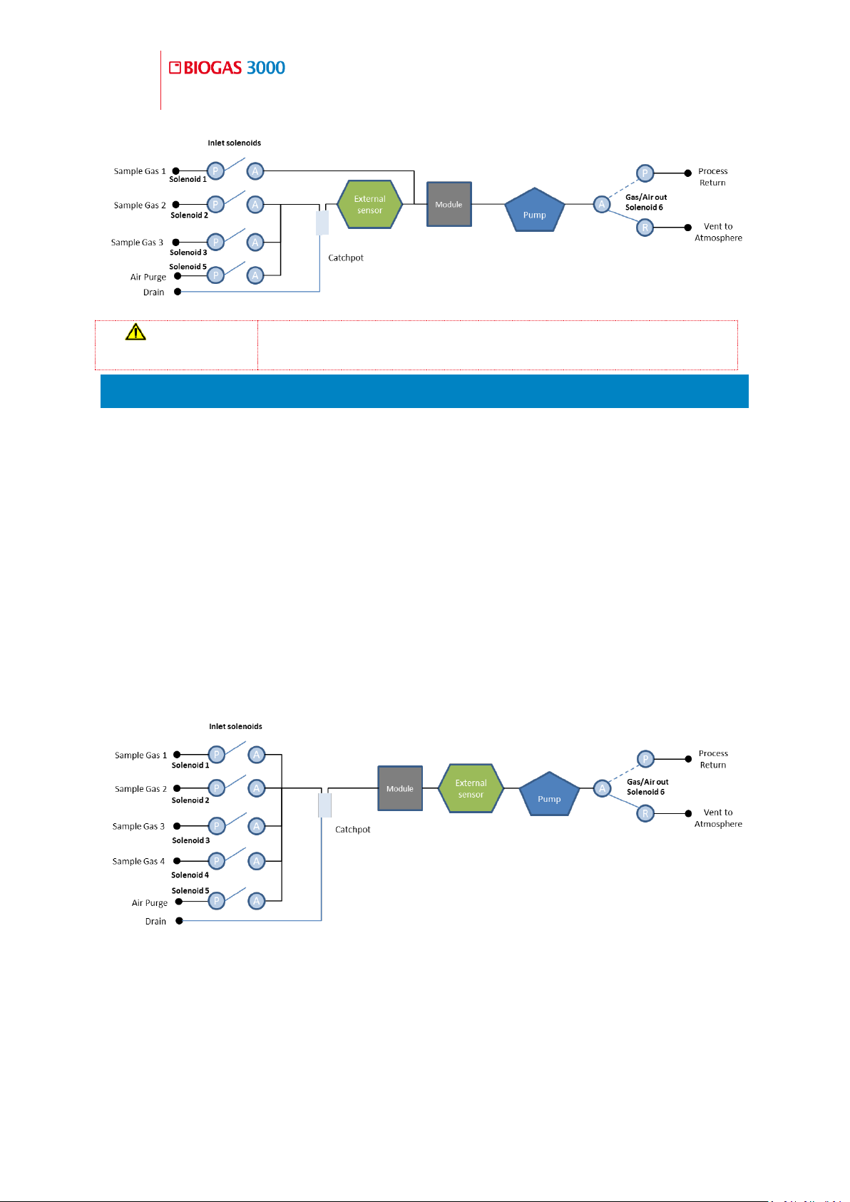
BG3K3 3.5.3
The BG3K3 measures CH
, CO2, and O2 as standard with a choice of up
4
to two additional gases (one internal to the module and one external)
from three sample points.
It has user selectable sample and air purge intervals that are exhausted
back to the process and atmosphere respectively.
The 4-20mA and Modbus outputs are updated at the end of each
sample.
The following image is a simple block diagram of the system including
the optional external gas sensor:
The BG3K3 also has the option of measuring from the hydrolysis tank on
sample point 1 and not passing this gas across the external sensor. This
prolongs the life of the sensor. The following image is a block diagram if
the system with this option selected:
Page 22
22
Operating Manual
BIOGAS 3000 Overview
OMBG3000 – Iss.01
© Copyright 2016
Warning
For this option, additional moisture filtration will be
required external to the equipment on ‘Sample Gas 1’.
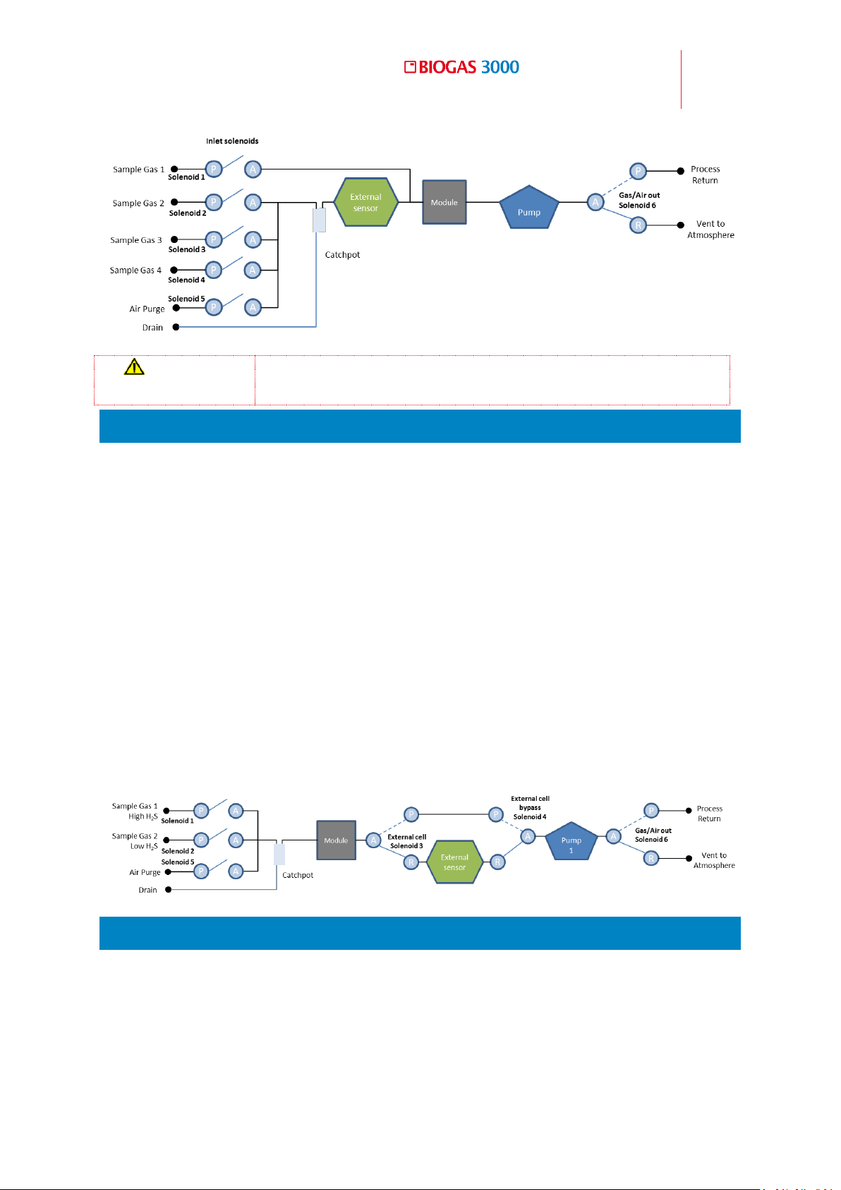
BG3K4 3.5.4
The BG3K4 measures CH
, CO2, and O2 as standard with a choice of up
4
to two additional gases (one internal to the module and one external)
from four sample points.
It has user selectable sample and air purge intervals that are exhausted
back to the process and atmosphere respectively.
The 4-20mA and Modbus outputs are updated at the end of each
sample.
The following image is a simple block diagram of the system including
the optional external gas sensor:
The BG3K4 also has the option of measuring from the hydrolysis tank on
sample point 1 and not passing this gas across the external sensor. This
prolongs the life of the sensor. The following image is a block diagram if
the system with this option selected:
Page 23
Operating Manual
BIOGAS 3000 Overview
23
© Copyright 2016
OMBG3000 – Rev1
Warning
For this option, additional filtration will be required
external to the equipment on ‘Sample Gas 1’.
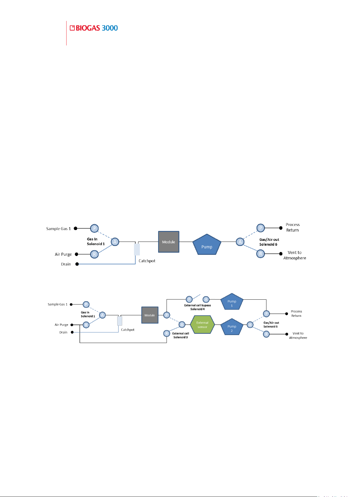
BG3KD 3.5.5
The BG3KD measures CH
, CO2, O2 and high and low range H2S as
4
standard (high range internal to the module and low range external)
from two sample points.
It has user selectable sample and air purge intervals that are exhausted
back to the process and atmosphere respectively.
The system has bypass solenoids in order to divert high levels of H
S
2
from the low range sensor, which will prolong its life.
The 4-20mA and Modbus outputs are updated at the end of each
sample.
The following image is a simple block diagram of the system:
BG3KE 3.5.6
The BG3KE measures CH
, CO2, and O2 as standard with a choice of up
4
to one additional gas (external to module only) from one sample point.
It measures CH
, CO2, and O2 continuously that is exhausted back to the
4
process.
Page 24
24
Operating Manual
BIOGAS 3000 Overview
OMBG3000 – Iss.01
© Copyright 2016
The module has a minimum three-minute air purge every 24-hours. The
duration and time of day this occurs is user-definable.
The external sensor has user selectable sample intervals that are
exhausted back to the process. The external sensor cannot be subjected
to the gas stream continuously.
After each defined cycle, the external sensor is subjected to a user
definable air purge that is exhausted to the atmosphere.
The 4-20mA and Modbus outputs are updated continuously, with the
external sensor data being refreshed at the end of each sample
The following images are two simple block diagrams of the system with
one including the optional external gas sensor:
BG3KE with no external sensor
BG3KE with an external sensor
Page 25
Operating Manual
BIOGAS 3000 Overview
25
© Copyright 2016
OMBG3000 – Rev1
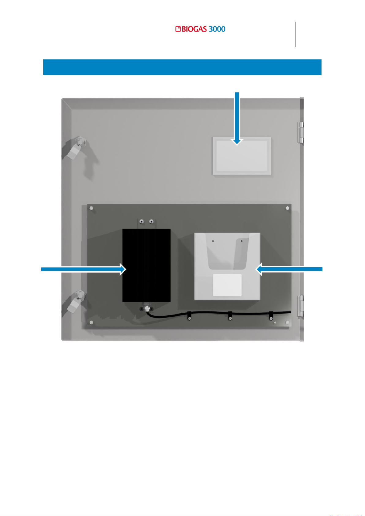
1)
Viewing window
2)
Heater (110V or 230V)
3)
Plastic wallet containing operating manual and calibration certificate
1
2
3
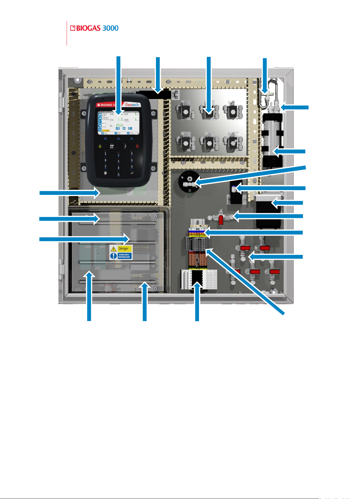
3.6 BIOGAS 3000 Internal Components
Figure 1 - BIOGAS 3000 door internals
Page 26
26
Operating Manual
BIOGAS 3000 Overview
OMBG3000 – Iss.01
© Copyright 2016
1)
BIOGAS 3000 module
11)
Modbus terminals
2)
Heater thermostat
12)
Gas in/out valves
3)
Solenoid valves
13)
4-20mA terminals
4)
Inline PTFE filter
14)
Relays
5)
Female QRC for calibration
15)
Mains supply terminals
6)
Catchpot with liquid level switch
16)
Power supplies
7)
External sensor
17)
Fuses
8)
Pumps
18)
Protective cover
9)
Auto-drain pump (or drain valve)
19)
Interface PCB
10)
Calibration valve
15
1
2
3
6
8
9
7
10
11
12
13
14
16
17
18
19 4 5
Figure 2 - BIOGAS 3000 internal components
Page 27
Operating Manual
BIOGAS 3000 Overview
27
© Copyright 2016
OMBG3000 – Rev1
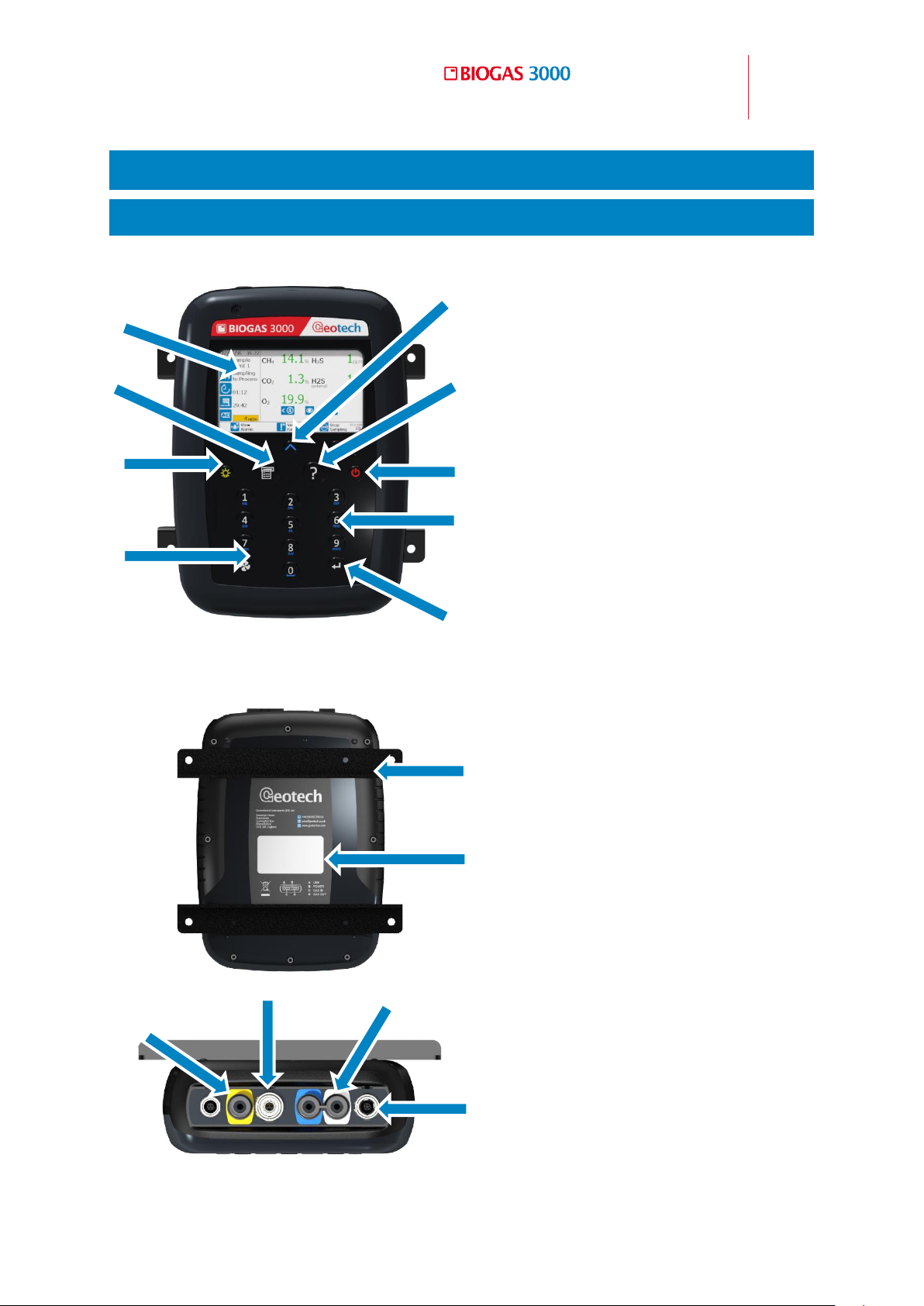
Front View:
Reference:
1) Display
2) Soft keys
3) Help key
4) On/off key
5) Keypad
6) Return key ( )
7) Pump key
8) Backlight key
9) Menu key
Rear View:
10) Module mounting brackets
11) Rear label
Top View:
12) Gas outlet
13) Power supply connector
14) Gas inlet
15) Communications connector
1 2 3 4 5
6
7
8
9
10
11
13
12
14
15
3.7 BIOGAS 3000 Module Features
Physical Characteristics of the Module 3.7.1
Page 28

28
Operating Manual
BIOGAS 3000 Overview
OMBG3000 – Iss.01
© Copyright 2016
Page 29

Operating Manual
BIOGAS 3000 Overview
29
© Copyright 2016
OMBG3000 – Rev1
Reference
Definition
1) Display
Shows information to the user.
2) Soft keys
The function of the three soft keys on the
keypad is determined by the screen the
operator is in.
3) Help key
Where ‘?’ is shown on the display, the
operator can press the help key for onscreen assistance.
4) On/off key
Press the on/off key for two seconds to
switch the module on and off.
5) Keypad
Allows numeric entry from 0-9 and letters
A-Z.
Keys ‘2’, ‘4’, ‘6’ and ‘8’ allow the operator
to navigate ‘up’, ‘right’, ‘left’ and ‘down’
respectively in certain menu items.
Key ‘0’ is also used as the space key when
entering text.
6) Return key ( )
The accepts/confirms choices made by
the operator for various functions and
operations.
7) Pump key
Not used in normal operation but is used
to aid diagnostics and assist with
maintenance. It does not control the
pump.
8) Backlight key
Enables the operator to turn the backlight
off and on.
9) Menu key
Press the ‘menu’ key to navigate to the
‘menu’.
Definitions 3.7.2
Front View
Page 30

30
Operating Manual
BIOGAS 3000 Overview
OMBG3000 – Iss.01
© Copyright 2016
10) Module mounting brackets
Securely holds the module to the
backplate.
11) Rear label
The serial number is the unique
identification number for the BIOGAS
3000 module. The part number is the
unique record for the internal
configuration of the BIOGAS 3000 module
at time of manufacture or last service.
12) Gas outlet
The gas sample exits the BIOGAS 3000
module here.
13) Power supply connector
Power supplied from the Interface PCB
connects here.
14) Gas inlet
The gas sample enters the BIOGAS 3000
module here.
15) Communications connector
Connection point for the USB lead from
the Interface PCB.
Rear View
Top View
Page 31
Operating Manual
Installation
31
© Copyright 2016
OMBG3000 – Rev1
Warning
Power should NOT be applied before all piping and
wiring has been completed and tested.
Only a qualified person should make electrical
connections to the system.
Installation 4
4.1 Pre-Installation Requirements
General 4.1.1
It is LANDTEC’s recommendation that the installation of the BIOGAS 3000 is
carried out in accordance with this operating manual and the latest edition of
IEC 60079-14. Any electrical work should be carried out by a competent
electrician and any relevant codes of practice should be followed.
In order to effectively install the BIOGAS 3000 system it is important that the
site is ready and in a fit state. In particular, the following points should be
noted:
This operating manual has been read and fully understood
A risk assessment has been performed that includes installation,
operation, and maintenance of the system and the removal, where
practicably possible, of any identified hazards
Applicable codes of practice identified
The BIOGAS 3000 system has been received on site, unpacked,
packaging contents checked, and checked for obvious damage
A suitable location is determined for the installation of the
instrumentation
Note: Refer to section Mounting the Enclosure for items that need to be
considered.
A suitable mains supply as detailed in this manual is installed
All required gas lines are installed
Page 32

32
Operating Manual
Installation
OMBG3000 – Iss.01
© Copyright 2016
Note: Inlet pressure to the BIOGAS 3000 system must not exceed 350
mbars (5psi). Where this is exceeded, additional pressure regulation is
required.
Output data cable has been installed (if required) to the BIOGAS 3000
location.
Note: Failure to comply with any of the above may result in additional
time on site and additional costs.
Packaging Contents 4.1.2
Check the product box for the following items:
BIOGAS 3000 system
Key for enclosure locks
Operating manual – found in plastic wallet on the inside of the
enclosure door
Customer wiring diagram – found in plastic wallet on the inside of the
enclosure door
Calibration certificate – found in plastic wallet on the inside of the
enclosure door
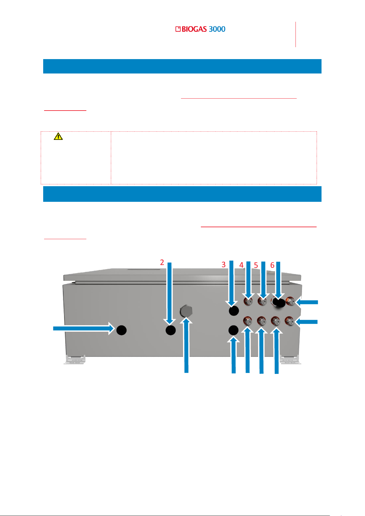
Compression fittings – found on the bulkheads on the enclosure base
(see annotations 4, 5, and 7-11 on Figure 3 - BIOGAS 3000 customer
connections)
Particulate filter for air purge line (LANDTEC part number 2008277/S,
see section BIOGAS 3000 Consumable Products).
Storage of the System and Module 4.1.3
The BIOGAS 3000 system and module should not be exposed to extremes of
temperature. It is the user’s responsibility to ensure the system and module
are kept within their ambient operating temperature range.
Page 33
Operating Manual
Installation
33
© Copyright 2016
OMBG3000 – Rev1
Warning
If the system is being installed indoors, it is our
recommendation that a suitable gas leak detector is
placed nearby to the system to inform operators of a
leak before entering the room. This is not supplied by
LANDTEC or QED.
1)
Customer cable entry – mains supply
8)
Drain
2)
Customer cable entry – not used
9)
Vent to Atmosphere
3)
Customer cable entry – data outputs
10)
Sample Gas 4
4)
Sample Gas 1
11)
Sample Gas 2
5)
Sample Gas 3
12)
Customer cable entry – relays
6)
Air In
13)
Breather Drain
7)
Process Return
1
7 8 9
10
11
12
13
Ventilation Requirements 4.1.4
There is an enclosure breather fitted to the BIOGAS 3000 situated at the base
of the enclosure (see annotation 13 on Figure 3 - BIOGAS 3000 customer
connections). It is the user’s responsibility to ensure that there is a free
circulation of air around the cabinet.
4.2 External Customer Connections
The installation will require the operator to connect a mains cable, output
cable, drain and gas pipes to the equipment. Figure 3 - BIOGAS 3000 customer
connections identifies the available connection points on the BIOGAS 3000:
Figure 3 - BIOGAS 3000 customer connections
Page 34
34
Operating Manual
Installation
OMBG3000 – Iss.01
© Copyright 2016
Warning
The mains and output cables must enter the cabinet via
a cable gland (see Cable Gland Selection and Cord
Anchorage) and the mains supply should be isolated (see
Mains Wiring).
Note: There are four stopping plugs fitted to the enclosure for the
customer’s cable entry. An M20 stopping plug must be removed from
annotations 1-3 and 12 where a cable gland is to be placed. Where a
cable entry point is not being used, the M20 stopping plug must remain
in place in order to maintain the IP rating of the enclosure.
4.3 Mounting the Enclosure
The system is contained in one enclosure that is weatherproof and has a rating
of IP65.
When considering the location of the equipment, the following must be
considered:
Although the enclosure is IP65, it must be protected from the worst of
the weather. For example, maintenance of the system will be made
easier and safer if it is not exposed to driving rain
Allow easy access for routine maintenance to be undertaken
Allow easy viewing of the display through the viewing window
Any future changes in the area, for example plantation growth causing
damage to pipework
Ensure there is no risk of damage from vehicles or animals in the area
Avoid positioning the enclosure in direct sunlight as this may increase
the internal temperature of the cabinet to outside of the operating
temperature range of the equipment.
Note: If it is difficult to position the BIOGAS 3000 system out of direct
sunlight, measures should be taken to protect the system, such as a
basic cover to provide shade.
The enclosure is to be mounted to a solid brick wall or framework (preferably
stainless steel) capable of holding the weight of the system. The weight of the
Page 35
Operating Manual
Installation
35
© Copyright 2016
OMBG3000 – Rev1
Warning
Although the wall mounting brackets are fitted and
tested at manufacture, during transit it is possible that
they could have worked loose. Prior to installation,
ensure the wall mounting brackets are securely fitted to
the BIOGAS 3000 system.
enclosure and contents will depend on the options that are fitted, but the
maximum weight is 32kg. It is therefore recommended that the installation be
undertaken by a minimum of two people.
Four mounting brackets are supplied and fitted to each corner of the BIOGAS
3000. Suitable nut and bolt or rawl bolt arrangements will have to be defined
by the operator for fixing to the wall or framework (it is recommended that
these are stainless steel). The enclosure should be mounted as square and
level as possible.
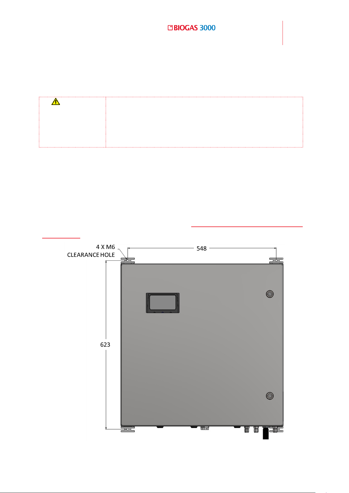
Dimensions of the enclosure are provided in Figure 4 - BIOGAS 3000 enclosure
dimensions.
Figure 4 - BIOGAS 3000 enclosure dimensions
Page 36
36
Operating Manual
Installation
OMBG3000 – Iss.01
© Copyright 2016
4.4 Connecting the Gas Lines to the BIOGAS 3000
Note: The gas connections on the system are ¼ inch stainless steel
bulkhead connectors with a compression fitting suitable for ¼ inch outer
diameter tubing. It is recommended that stainless steel tubing be used
where possible.
Note: After installation, ensure all tube connections are tight and free
from leaks. See section Pressure Test.
Gas Sample Lines 4.4.1
Care should be taken in routing the sample lines, especially in cold
environments. The sample lines may need insulating or even trace heating to
prevent freezing of water within the pipe. This is not part of the BIOGAS 3000
system and is the responsibility of the operator.
The sample should be taken from a suitable location at the required
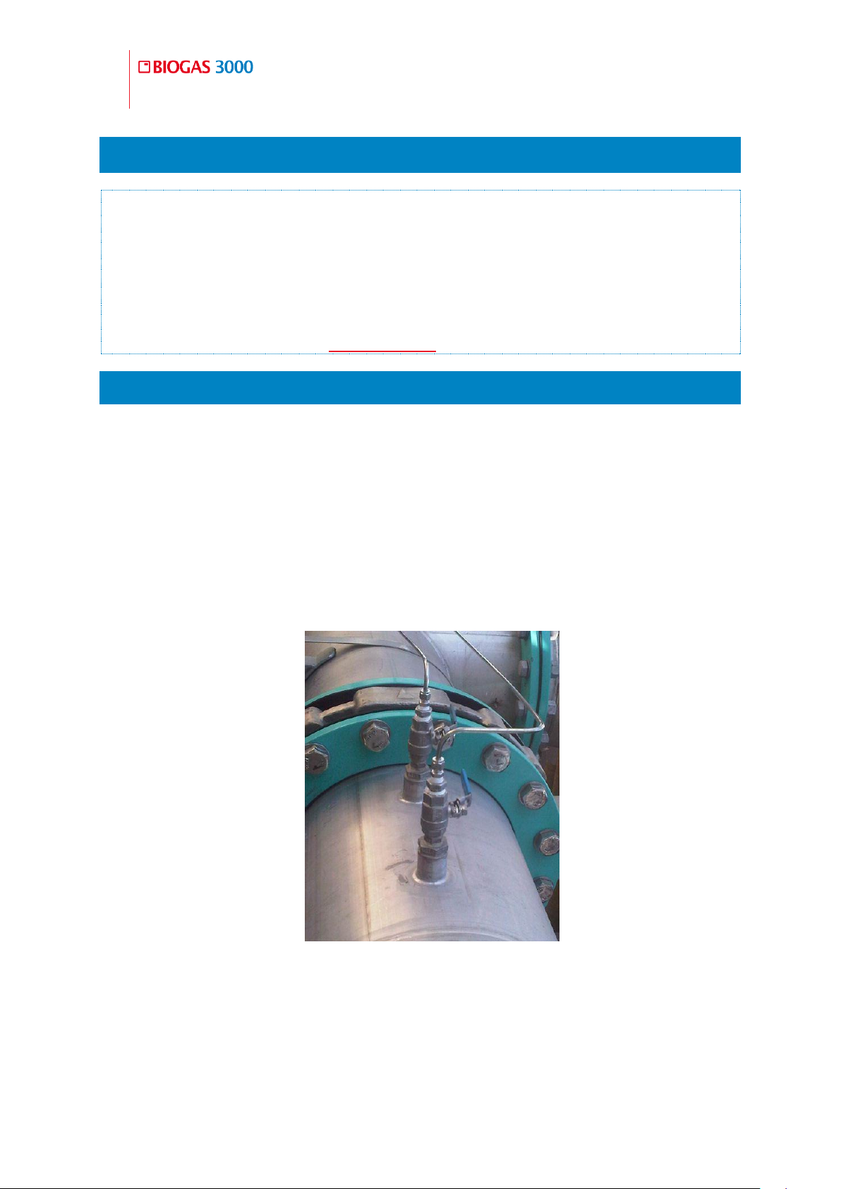
monitoring point. It is recommended that a valve be incorporated in the
assembly so that the gas can be shut off if the sample line is removed.
Figure 5 - Ball valve assembly
The line should connect to the upper surface of a horizontal pipe or on
a vertical standing pipe. This will prevent excessive amounts of water
entering the sample line.
Page 37
Operating Manual
Installation
37
© Copyright 2016
OMBG3000 – Rev1
Warning
The gas being exhausted at this point of the system will
be flowing at approximately 300ml/min. If the sample
gas is being vented to atmosphere, it should be routed
to a safe and well-ventilated area.
An additional ball valve should be incorporated in to each sample line
close to the BIOGAS 3000 system. This ball valve will be used to isolate
the gas supply to the system as part of pressure testing the system
during routine maintenance.
The sample tube should be connected to the bulkhead connectors
labelled ‘SAMPLE GAS 1’, ‘SAMPLE GAS 2’, ‘SAMPLE GAS 3’, and
‘SAMPLE GAS 4’ where applicable – see annotations 4, 5, 10, and 11 on
Figure 3 - BIOGAS 3000 customer connections.
Note: The maximum distance the BIOGAS 3000 can be from the sample
point is 164 feet, (50 meters).
Process Return 4.4.2
This is the line where measured gas from the system is exhausted. It can be
returned to the process or vented to atmosphere.
Care should be taken in routing the process return line, especially in cold
environments. The process return line may need insulating or even trace
heating to prevent freezing of water within the pipe. This is not part of the
BIOGAS 3000 system and is the responsibility of the operator.
The gas exhaust line should be returned to a suitable location at the
required point. It is recommended that a valve be incorporated in the
assembly so that the gas can be shut off if the sample line is removed.
See Figure 5 - Ball valve assembly.
An additional ball valve should be incorporated in to the piping close to
the BIOGAS 3000 system, even when being vented to atmosphere. This
ball valve will be used as part of pressure testing the system during
routine maintenance.
Page 38
38
Operating Manual
Installation
OMBG3000 – Iss.01
© Copyright 2016
Warning
When performing an air purge the gas that was
previously sampled will be vented to atmosphere for a
short period, typically 10 seconds. This equates to
approximately 50ml of gas per air purge. In addition,
when performing a user calibration, the calibration gas
will be exhausted from this bulkhead. It is therefore
recommended that the ‘Vent to Atmosphere’ line should
be routed to a safe and well-ventilated area.
The gas exhaust line should be connected to the bulkhead connector
labelled ‘PROCESS RETURN’ – see annotation 7 on Figure 3 - BIOGAS
3000 customer connections.
Air In 4.4.3
The air purge inlet requires uncontaminated air for the purge line. If
uncontaminated air is available, the particulate filter should remain in place.
If uncontaminated air cannot be guaranteed at the location of the analyser, the
particulate filter should be removed and a pipe should be connected in its
place and terminated at a point where uncontaminated air is present.
The sample tube should be connected to the bulkhead connector
labelled ‘AIR IN’ – see annotations 6 on Figure 3 - BIOGAS 3000
customer connections.
Vent to Atmosphere 4.4.4
A ball valve should be incorporated in to the piping close to the BIOGAS
3000 system. This ball valve will be used as part of pressure testing the
system during routine maintenance.
The sample tube should be connected to the bulkhead connector
labelled ‘VENT TO ATMOSPHERE’ – see annotation 9 on Figure 3 -
BIOGAS 3000 customer connections.
4.5 Drain
The system incorporates a catchpot and drain for removal of liquid to help
prevent water from entering the system (see annotation 6 on
Page 39

Operating Manual
Installation
39
© Copyright 2016
OMBG3000 – Rev1
Figure 2 - BIOGAS 3000 internal components). However, additional water
filtering may be required where the sample is heavily contaminated with water
(available from LANDTEC, see part number GA3KP.S15 in section BIOGAS 3000
Consumable Products).
Care should be taken in routing the drain line, especially in cold environments.
The drain line may need insulating or even trace heating to prevent freezing of
water within the pipe. This is not part of the BIOGAS 3000 system and is the
responsibility of the operator.
Alternatively, the contents can be emptied in to a suitable container and
disposed of in a safe manner.
If the auto-drain option is fitted, no manual draining of the system is required.
The drain line should be connected to the bulkhead connector labelled
‘DRAIN’ – see annotation 8 on Figure 3 - BIOGAS 3000 customer
connections.
The drain line should be run to a position where it is safe to discharge
the small amount of liquid that is removed from the sample gas.
The contents of the catchpot are drained under gravity. Therefore, any
tubing needs to be lower than the drain compression fitting.
The drain connection on the system is a 6mm stainless steel bulkhead
connector with a compression fitting suitable for 6mm outer diameter
tubing. It is recommended that stainless steel tubing be used where
possible.
The catchpot contains a liquid level (reed) switch. When the liquid
reaches a certain level, the switch activates and informs the BIOGAS
3000 module. From here, an icon is displayed on screen and if
configured triggers a relay (see Configure Relays).
Refer to the Emptying the Catchpot section of this operating manual for
how to drain the catchpot.
When taking a gas sample, ensure the drain ball valve (see annotation 9
on
Page 40

40
Operating Manual
Installation
OMBG3000 – Iss.01
© Copyright 2016
Warning
For the hydrolysis tank option chosen at manufacture,
additional filtration will be required on sample point 1,
as this does not pass through the system’s catchpot. See
LANDTEC part number GA3KP.S15 in section BIOGAS
3000 Consumable Products
The catchpot can hold approximately 90ml of liquid.
Dependent upon the application the liquid removed may
be contaminated and should be discharged to an area
where it is safe to do so.
This line may also vent sample gas for a brief period
during each draining operation if the sample inlet and
gas out valves are not closed.
Figure 2 - BIOGAS 3000 internal components is in the closed (horizontal)
position.
Note: If the auto-drain option is fitted, there will be no drain valve fitted
to the equipment.
Page 41

Operating Manual
Installation
41
© Copyright 2016
OMBG3000 – Rev1
Warning
The cover must only be removed when power to the
system has been isolated. Failure to isolate the power
before removing the cover could result in an electric
shock.
It is vital that after installation and prior to powering the
equipment that the protective cover is replaced. Failure
to replace the cover could result in an electric shock.
4.6 Protective Cover
The BIOGAS 3000 has a protective cover fitted inside the main enclosure to
cover areas where mains voltages are present. This cover must be removed in
order to wire the mains supply to the BIOGAS 3000 system and to replace
fuses.
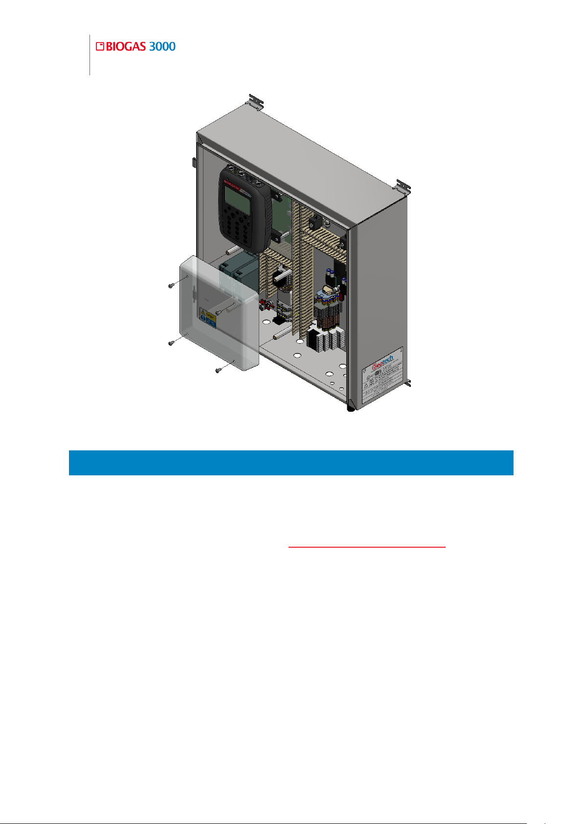
The cover is removed by unscrewing four M6 x 12mm button head screws with
a 4mm hexagon tool (see Figure 6 - Mains cover removal). The cover and
screws must be kept safe once removed to ensure that they are not lost and
can be refitted once installation is complete.
To fit the cover, simply align the holes in the protective cover with the four
pillars fixed to the BIOGAS 3000 back plate and screw in to place using the
4mm hexagon tool.
Note: For clarity, some images of the BIOGAS 3000 system in this
operating manual may not include the protective cover.
Page 42
42
Operating Manual
Installation
OMBG3000 – Iss.01
© Copyright 2016
Figure 6 - Mains cover removal
4.7 Cable Gland Selection and Cord Anchorage
To maintain the integrity and certification of the equipment a cable gland must
be selected that:
is suitably certified – see section ATEX and IECEx Certification in this
operating manual for the equipment marking
has a minimum rating of IP65
shall be protected against abrasion and sharp bends at the point where
the cord enters the equipment, by an inlet or bushing with a smoothly
rounded opening
has been fitted and tightened to the recommended torque set by the
In addition, the cable gland must have a means of anchoring the cable. The
cord anchorage shall relieve the conductors of the cord from strain, including
manufacturer.
Page 43

Operating Manual
Installation
43
© Copyright 2016
OMBG3000 – Rev1
Warning
A compression bushing shall not be used as cord
anchorage.
Failure to meet the above requirements could make the
equipment unsafe resulting in a hazard and invalidate
the ATEX/IECEx certification.
twisting, where they are connected within the equipment, and shall protect
the insulation of the conductors from abrasion. The protective earth conductor
shall be last to take the strain if the cord slips in its anchorage.
Cord anchorages shall meet the following requirements:
The cord shall not be clamped by a screw that bears directly on the cord
Knots in the cord shall not be used
It shall not be possible to push the cord into the equipment to an extent
that could cause a hazard
Failure of the cord insulation in a cord anchorage that has metal parts
shall not cause accessible conductive parts to become hazardous live
It shall not be possible to loosen the cord anchorage without the use of
a tool
It shall be designed so that cord replacement does not cause a hazard,
and it shall be clear how the relief from strain is provided.
Page 44
44
Operating Manual
Installation
OMBG3000 – Iss.01
© Copyright 2016
Function
Type
Conductor Size
Voltage
Rating
Current
Rating
Mains
supply
Tri-rated
0.14 – 4.0mm2 solid
0.14 – 2.5mm2 stranded
230Vac
3.15A
4-20mA
outputs
Twisted
pair
0.14 – 4.0mm2 solid
0.14 – 2.5mm2 stranded
24Vdc
20mA
Modbus
outputs
Twisted
pair
0.14 – 4.0mm2 solid
0.14 – 2.5mm2 stranded
12Vdc
83.3mA
Relays
Tri-rated
0.2 – 2.5mm2
24Vdc
6A
Warning
Failure to meet the above requirements could make the
equipment unsafe resulting in a hazard and invalidate
the ATEX/IECEx certification.
Function
Cable Insulation thickness (min)
Mains supply
0.6mm
4-20mA outputs
0.2mm
Modbus outputs
0.2mm
Relays
0.2mm
Warning
Failure to meet the above requirements could make the
equipment unsafe resulting in a hazard and invalidate
the ATEX/IECEx certification.
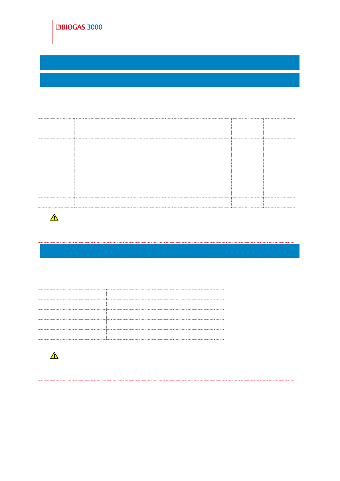
4.8 Cable Conductor Sizes and Insulation Requirements
Cable Conductor Sizes 4.8.1
Cable conductors must meet the following requirements, be suitable for the
environment, and distance to the supply:
Cable Insulation Requirements 4.8.2
In addition to the table below, the cable insulation must comply with a
recognised standard and have a flammability rating of V1 or better:
Page 45
Operating Manual
Installation
45
© Copyright 2016
OMBG3000 – Rev1
4.9 Mains Wiring
Protective Earthing and Mains Supply 4.9.1
The safety of the equipment depends on it being effectively earthed via the
mains supply.
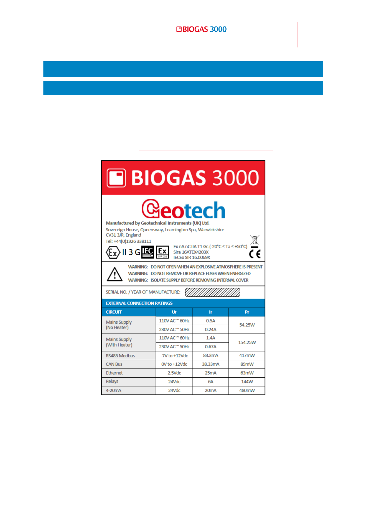
The mains requirement for the system can be found on the side of the
enclosure and is shown on Figure 7 - BIOGAS 3000 electrical label:
The mains fuse rating (FS1) of the equipment is 3.15A.
The equipment must be provided with a double-pole switched and fused mains
supply. The switch must be mounted as close to the equipment as practicably
Figure 7 - BIOGAS 3000 electrical label
Page 46
46
Operating Manual
Installation
OMBG3000 – Iss.01
© Copyright 2016
Warning
Only a qualified person should make electrical
connections to the system.
Ensure the power is isolated and the Protective Cover is
removed before wiring to the system.
Failure to connect a suitable earth to the system could
result in serious injury.
The equipment must be provided with a double-pole
switched and fused mains supply. The switch must be
mounted as close to the equipment as practicably
possible and clearly identified as the disconnecting
device for the system.
Cable glands should meet the requirements of Cable
Gland Selection and Cord Anchorage.
Cable insulation and conductor sizes must meet the
requirements of Cable Conductor Sizes and Insulation
Requirements.
If using armored cable, the armor must not be used as
the main earth connection for the BIOGAS 3000. If
earthing of the armor is required, this must not be taken
from the BIOGAS 3000.
All cables should be crimped with an appropriate
insulated ferrule for the size of the cable being used. In
addition, the cable insulation must be housed
adequately within the protective sheath of the ferrule.
possible so that it can be easily reached and clearly identified as the
disconnecting device for the system.
The mains cable must be three core cable (live, neutral and earth) and enter
the enclosure via a cable gland (see Cable Gland Selection and Cord
Anchorage) through the mains supply customer cable entry point (see
annotation 1 on Figure 3 - BIOGAS 3000 customer connections).
How to Wire the Mains Supply 4.9.2
Page 47
Operating Manual
Installation
47
© Copyright 2016
OMBG3000 – Rev1
Terminals that are wired should be tightened to a
minimum of 0.6Nm. Failure to tighten to this
requirement could make the equipment unsafe resulting
in a hazard and invalidate the ATEX/IECEx certification.
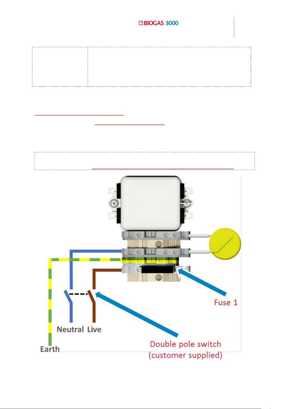
Refer to annotation 15 on
Figure 2 - BIOGAS 3000 internal components for the location of the mains
wiring terminals, and Wiring Diagram 1 - Mains for how to wire the mains
cable to the BIOGAS 3000 system. A label within the system identifies the
appropriate inputs live (L), earth (E), and neutral (N).
Note: For cable conductor sizes and cable insulation requirements, please
refer to section Cable Conductor Sizes and Insulation Requirements.
Wiring Diagram 1 - Mains
Page 48
48
Operating Manual
Installation
OMBG3000 – Iss.01
© Copyright 2016
Warning
The BIOGAS 3000 Modbus terminals must only be used
for standard Modbus communications. No other
connections must be made as they could make the
equipment unsafe resulting in a hazard and invalidate
the ATEX/IECEx certification.
Warning
Only a qualified person should make electrical
connections to the system.
Ensure the power is isolated.
Cable glands should meet the requirements of Cable
Gland Selection and Cord Anchorage.
Cable insulation and conductor sizes must meet the
requirements of Cable Conductor Sizes and Insulation
Requirements.
If using armored cable, the armor must not be used as
the main earth connection for the BIOGAS 3000. If
earthing of the armor is required, this must not be taken
from the BIOGAS 3000.
All cables should be crimped with an appropriate
insulated ferrule for the size of the cable being used. In
addition, the cable insulation must be housed
4.10 Modbus Digital Output
If Modbus digital outputs are being used, the cable must enter the enclosure
via a suitably rated cable gland (see Cable Gland Selection and Cord
Anchorage) and cable (see Cable Conductor Sizes and Insulation
Requirements), through the data outputs customer cable entry point (see
annotation 3 on Figure 3 - BIOGAS 3000 customer connections).
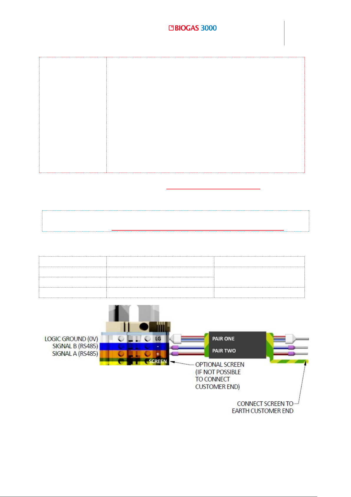
A label within the system identifies the appropriate outputs ‘+’, ‘-‘, and ‘LG’.
Refer to annotation 10 on Figure 2 - BIOGAS 3000 internal components for the
Modbus terminal connections.
Wiring the BIOGAS 3000 Modbus Outputs 4.10.1
Page 49
Operating Manual
Installation
49
© Copyright 2016
OMBG3000 – Rev1
Terminal Colour
Wiring Information
Pair
Orange
Signal A (RS485) ‘+’
Pair one
Blue
Signal B (RS485) ‘-‘
White
Logic Ground (0V) ‘LG’
Pair two
adequately within the protective sheath of the ferrule.
Terminals that are wired should be tightened to a
minimum of 0.6Nm. Failure to tighten to this
requirement could make the equipment unsafe
resulting in a hazard and invalidate the ATEX/IECEx
certification.
The input voltage range to the BIOGAS 3000 Modbus
terminals must not exceed -7 to +12V and the current
must not exceed 83.3mA. Operating outside of this
range will invalidate the ATEX/IECEx certification.
Wire the outputs in accordance with Wiring Diagram 2 – Modbus. For optimum
performance, it is recommended that screened twisted pair cable be used.
Note: For cable conductor sizes and cable insulation requirements, please
refer to section Cable Conductor Sizes and Insulation Requirements.
When wiring the outputs the twisted pairs must be as follows:
Wiring Diagram 2 – Modbus
Page 50
50
Operating Manual
Installation
OMBG3000 – Iss.01
© Copyright 2016
Node Address
1
Baud Rate
19200
Parity
Even
Stop Bits
1
Termination
Off
The BIOGAS 3000 acts as a slave.
The protocol is MODBUS RTU.
Register
Address
(Dec)
(Hex)
Parameter
Content Information
0
0000h
System status
0 – system OK
1 – system fault
1
0001h
Flow status
0 – flow OK
1 – flow fail
2
0010h
Communications
status
0 – communications OK
1 – communications error
3
0011h
Catchpot status
0 – catchpot empty
1 – catchpot full
Default Configuration of the BIOGAS 3000 Modbus Port 4.10.2
The BIOGAS 3000 Modbus port has a default configuration of the following:
Note: A termination resistor of 200 ohms is fitted internally between the
positive and negative Modbus signals of the BIOGAS 3000, which must be
the last connection on the ‘bus’. The termination resistor can be turned
‘On’ or ‘Off’ via the menu on the BIOGAS 3000 module (see Configure
Modbus Slave). Similarly, the master device on the ‘bus’ should have a
termination resistor.
Note: The node address, baud rate, parity, and termination are all
configurable settings found within the menu of the BIOGAS 3000 module;
see section Configure Modbus Slave.
Readable Parameters of the BIOGAS 3000 4.10.3
Below is a table of addresses that can be read from the BIOGAS 3000.
Read-Only Single Bit Registers
Page 51

Operating Manual
Installation
51
© Copyright 2016
OMBG3000 – Rev1
Page 52

52
Operating Manual
Installation
OMBG3000 – Iss.01
© Copyright 2016
Register
Address
(Dec)
(Hex)
Parameter
Content Information
0
0000h
Run status
0 – running process
1 – running with non-critical fault
2 – stopped by user (outputs frozen)
3 – stopped by user (fixed at safe
values)
4 – stopped with critical fault
(outputs frozen)
32
0020h
Time and date: year
e.g. 2016
33
0021h
Time and date:
Month
1-12
34
0022h
Time and date: day
1-31
35
0023h
Time and date: hour
0-23
36
0024h
Time and date:
minute
0-59
37
0025h
Time and date:
second
0-59
48
0030h
Current sample
point
1-4
128
0080h
Service due: year
e.g. 2016
129
0081h
Service due: month
1-12
130
0082h
Service due: day
1-31
512
0200h
Alarm 1 Status
0 – No alarm
1 – Triggered
2 – Triggered and in recovering zone
4 – Latched
8 – Muted
9 – Triggered alarm and muted
10 – Recovering alarm and muted
12 – Latched and muted
513
to
519
0201h
to
0207h
Alarm 2 to alarm 7
Status
Repeated as per alarm 1
768
0300h
Sample point 1 last
reading: year
e.g. 2016
Read-Only 16-Bit Registers
Page 53

Operating Manual
Installation
53
© Copyright 2016
OMBG3000 – Rev1
769
0301h
Sample point 1 last
reading: month
1-12
770
0302h
Sample point 1 last
reading: day
1-31
771
0303h
Sample point 1 last
reading: hour
0-23
772
0304h
Sample point 1 last
reading: minute
0-59
773
0305h
Sample point 1 last
reading: second
0-59
1024
to
1029
0400h
to
0405h
Sample point 2 last
reading time and
date
Repeated as per sample point 1
1280
to
1285
0500h
to
0505h
Sample point 3 last
reading time and
date
Repeated as per sample point 1
1536
to
1541
0600h
to
0605h
Sample point 4 last
reading time and
date
Repeated as per sample point 1
832
0340h
Last reading sample
point 1: CH4
CH4 reading x 10
e.g. 61.1% would be 611
833
0341h
Last reading sample
point 1: CO2
CO2 reading x 10
e.g. 38.7% would be 387
834
0342h
Last reading sample
point 1: O
2
O2 reading x 10
e.g. 0.5% would be 5
835
0343h
Last reading sample
point 1: Internal cell
Internal cell reading
e.g. 3500
837
0345h
Last reading sample
point 1: External cell
External cell reading
e.g. 3500
839
0347h
Last reading sample
point 1: Baro
Baro reading
e.g. 1025
841
0349h
Last reading sample
point 1: Flow
Pump flow reading
e.g. 275
1088
0440h
Last reading sample
point 2: CH4
CH4 reading x 10
e.g. 61.1% would be 611
1089
0441h
Last reading sample
point 2: CO2
CO2 reading x 10
e.g. 38.7% would be 387
1090
0442h
Last reading sample
O2 reading x 10
Page 54

54
Operating Manual
Installation
OMBG3000 – Iss.01
© Copyright 2016
point 2: O
2
e.g. 0.5% would be 5
1091
0443h
Last reading sample
point 2: Internal cell
Internal cell reading
e.g. 3500
1093
0445h
Last reading sample
point 2: External cell
External cell reading
e.g. 3500
1095
0447h
Last reading sample
point 2: Baro
Baro reading
e.g. 1025
1097
0449h
Last reading sample
point 2: Flow
Pump flow reading
e.g. 275
1344
0540h
Last reading sample
point 3: CH4
CH4 reading x 10
e.g. 61.1% would be 611
1345
0541h
Last reading sample
point 3: CO2
CO2 reading x 10
e.g. 38.7% would be 387
1346
0542h
Last reading sample
point 3: O
2
O2 reading x 10
e.g. 0.5% would be 5
1347
0543h
Last reading sample
point 3: Internal cell
Internal cell reading
e.g. 3500
1349
0545h
Last reading sample
point 3: External cell
External cell reading
e.g. 3500
1351
0547h
Last reading sample
point 3: Baro
Baro reading
e.g. 1025
1353
0549h
Last reading sample
point 3: Flow
Pump flow reading
e.g. 275
1600
0640h
Last reading sample
point 4: CH4
CH4 reading x 10
e.g. 61.1% would be 611
1601
0641h
Last reading sample
point 4: CO2
CO2 reading x 10
e.g. 38.7% would be 387
1602
0642h
Last reading sample
point 4: O
2
O2 reading x 10
e.g. 0.5% would be 5
1603
0643h
Last reading sample
point 4: Internal cell
Internal cell reading
e.g. 3500
1605
0645h
Last reading sample
point 4: External cell
External cell reading
e.g. 3500
1607
0647h
Last reading sample
point 4: Baro
Baro reading
e.g. 1025
1609
0649h
Last reading sample
point 4: Flow
Pump flow reading
e.g. 275
Page 55

Operating Manual
Installation
55
© Copyright 2016
OMBG3000 – Rev1
Register
Address
(Dec)
(Hex)
Parameter
Content Information
33024
8100h
Last reading sample
point 1: CH4
CH4 reading
e.g. 61.1
33026
8102h
Last reading sample
point 1: CO2
CO2 reading
e.g. 38.7
33028
8104h
Last reading sample
point 1: O2
O2 reading
e.g. 0.5
33030
8106h
Last reading sample
point 1: Internal cell
Internal cell reading
e.g. 3500
33034
810Ah
Last reading sample
point 1: External cell
External cell reading
e.g. 3500
33038
810Eh
Last reading sample
point 1: Baro
Baro reading
e.g. 1025
33042
8112h
Last reading sample
point 1: Flow
Pump flow reading
e.g. 275
33280
8200h
Last reading sample
point 2: CH4
CH4 reading
e.g. 61.1
33282
8202h
Last reading sample
point 2: CO2
CO2 reading
e.g. 38.7
33284
8204h
Last reading sample
point 2: O2
O2 reading
e.g. 0.5
33286
8206h
Last reading sample
point 2: Internal cell
Internal cell reading
e.g. 3500
33290
820Ah
Last reading sample
point 2: External cell
External cell reading
e.g. 3500
33294
820Eh
Last reading sample
point 2: Baro
Baro reading
e.g. 1025
33298
8212h
Last reading sample
point 2: Flow
Pump flow reading
e.g. 275
33536
8300h
Last reading sample
point 3: CH4
CH4 reading
e.g. 61.1
33538
8302h
Last reading sample
CO2 reading
Read-Only 32-Bit Registers
Readings stored in two 16-bit read-only registers as a single precision
real/floating point number:
Page 56
56
Operating Manual
Installation
OMBG3000 – Iss.01
© Copyright 2016
point 3: CO2
e.g. 38.7
33540
8304h
Last reading sample
point 3: O2
O2 reading
e.g. 0.5
33542
8306h
Last reading sample
point 3: Internal cell
Internal cell reading
e.g. 3500
33546
830Ah
Last reading sample
point 3: External cell
External cell reading
e.g. 3500
33550
830Eh
Last reading sample
point 3: Baro
Baro reading
e.g. 1025
33554
8312h
Last reading sample
point 3: Flow
Pump flow reading
e.g. 275
33792
8400h
Last reading sample
point 4: CH4
CH4 reading
e.g. 61.1
33794
8402h
Last reading sample
point 4: CO2
CO2 reading
e.g. 38.7
33796
8404h
Last reading sample
point 4: O2
O2 reading
e.g. 0.5
33798
8406h
Last reading sample
point 4: Internal cell
Internal cell reading
e.g. 3500
33802
840Ah
Last reading sample
point 4: External cell
External cell reading
e.g. 3500
33806
840Eh
Last reading sample
point 4: Baro
Baro reading
e.g. 1025
33810
8412h
Last reading sample
point 4: Flow
Pump flow reading
e.g. 275
Note: Floating-point numbers consist of two 16-bit words to give a 32-bit
single precision floating point number. The first word (e.g. 33802) holds
the sign in bit 15, the exponent in bits 14-7, part of the mantissa in bits 6-
0. The remaining part of the mantissa is in the next register (e.g. 33803)
bits 15 – 0.
Page 57

Operating Manual
Installation
57
© Copyright 2016
OMBG3000 – Rev1
4.11 4-20mA Outputs
If analog outputs are being used, the cable must enter the enclosure via a
suitably rated cable gland (see Cable Gland Selection and Cord Anchorage) and
cable (see Cable Conductor Sizes and Insulation Requirements), through the
data outputs customer cable entry point (see annotation 3 on Figure 3 -
BIOGAS 3000 customer connections).
The outputs on the BIOGAS 3000 power the loop (24V) to allow the customers
system to sink it to ground (0V).
Relays within the equipment can be used to indicate the status of the 4-20mA
channel. Refer to section Configure Relays for more information.
Note: There are various combinations of configuring the system and this
operating manual will describe the most common method. If your system
does not support this, please contact our technical support team at (800)
968-2026 or email [email protected].
General Information 4.11.1
There are two sets of terminals for the 4-20mA signals. One set is a bank of
terminals that provide a common 0V or 24V. The other group are double-deck
terminals that provide the analogue signal depending on the configuration of
the common terminal.
For the common terminals, labels identify the appropriate terminals namely
from left to right (‘0V’, ‘T1’ through ‘T6’, ‘24V’). ‘T1’ to ‘T6’ are commoned
together using a 3-way bridge connector between either the ‘0V’ or the ‘24V’
terminal.
For the analog channels, labels identify the appropriate terminal on the
double-deck namely:
Refer to annotation 13 in
Top deck: ‘CH1A’ through ‘CH6A’
Bottom deck: ‘CH1B’ through ‘CH6B’
Page 58

58
Operating Manual
Installation
OMBG3000 – Iss.01
© Copyright 2016
Warning
Only a qualified person should make electrical
connections to the system.
Ensure the power is isolated.
Cable glands should meet the requirements of Cable
Gland Selection and Cord Anchorage.
Cable insulation and conductor sizes must meet the
requirements of Cable Conductor Sizes and Insulation
Requirements.
If using armored cable, the armor must not be used as
the main earth connection for the BIOGAS 3000. If
earthing of the armor is required, this must not be taken
from the BIOGAS 3000.
All cables should be crimped with an appropriate
insulated ferrule for the size of the cable being used. In
addition, the cable insulation must be housed
adequately within the protective sheath of the ferrule.
Terminals that are wired should be tightened to a
minimum of 0.6Nm. Failure to tighten to this
requirement could make the equipment unsafe
resulting in a hazard and invalidate the ATEX/IECEx
certification.
Figure 2 - BIOGAS 3000 internal components for the terminal location and
Wiring Diagram 3 - 4-20mA circuit for the 4-20mA terminal identification.
Wiring the BIOGAS 3000 to a Current Sinking Input 4.11.2
For this method, the power to the loop is provided by the BIOGAS 3000. The
BIOGAS 3000 sources the current.
Wire the outputs in accordance with Wiring Diagram 3 - 4-20mA circuit. For
optimum performance, it is recommended that screened twisted pair cable be
used.
Page 59
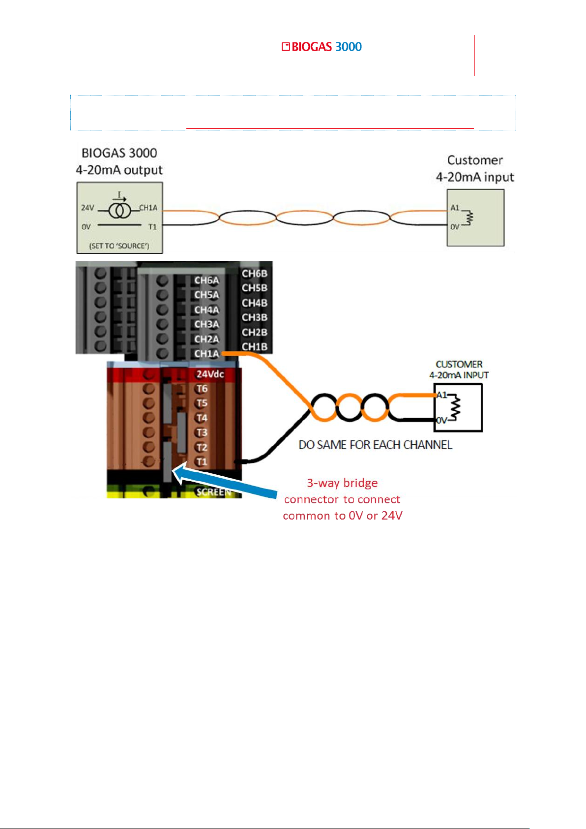
Operating Manual
Installation
59
© Copyright 2016
OMBG3000 – Rev1
Note: For cable conductor sizes and cable insulation requirements, please
refer to section Cable Conductor Sizes and Insulation Requirements.
Wiring Diagram 3 - 4-20mA circuit
Page 60
60
Operating Manual
Installation
OMBG3000 – Iss.01
© Copyright 2016
Gas
4mA Reading
20mA Reading
CH4 0.0%
100.0%
CO2
0.0%
100.0%
O2
0.0%
25.0%
H2S 0-50ppm
0ppm
50ppm
H2S 0-200ppm
0ppm
200ppm
H2S 0-500ppm
0ppm
500ppm
H2S 0-1,000ppm
0ppm
1,000ppm
H2S 0-5,000ppm
0ppm
5,000ppm
H2S 0-10,000ppm
0ppm
10,000ppm
H2 0-1,000ppm
0ppm
1,000ppm
CO 0-1,000ppm
0ppm
1,000ppm
4-20mA Scaling 4.11.3
The following table details the scaling on the 4-20mA channels:
Page 61

Operating Manual
Installation
61
© Copyright 2016
OMBG3000 – Rev1
Warning
Only a qualified person should make electrical
connections to the system.
Ensure the power is isolated.
Cable glands should meet the requirements of Cable
Gland Selection and Cord Anchorage.
Cable insulation and conductor sizes must meet the
requirements of Cable Conductor Sizes and Insulation
Requirements.
If using armored cable, the armor must not be used as
the main earth connection for the BIOGAS 3000. If
earthing of the armor is required, this must not be taken
from the BIOGAS 3000.
All cables should be crimped with an appropriate
insulated ferrule for the size of the cable being used. In
addition, the cable insulation must be housed
adequately within the protective sheath of the ferrule.
The maximum rated voltage of the relays to 24Vdc.
Exceeding this voltage will invalidate the ATEX/IECEx
certification.
Terminals that are wired should be tightened to a
minimum of 0.6Nm. Failure to tighten to this
requirement could make the equipment unsafe
resulting in a hazard and invalidate the ATEX/IECEx
certification.
4.12 Relays
Note: The relays are configurable for alarm notifications, sample point
monitoring notifications, air purge notifications, catchpot full
notifications, and 4-20mA signal notifications. The configuration is set-up
via the menu (see section Configure Relays).
Page 62
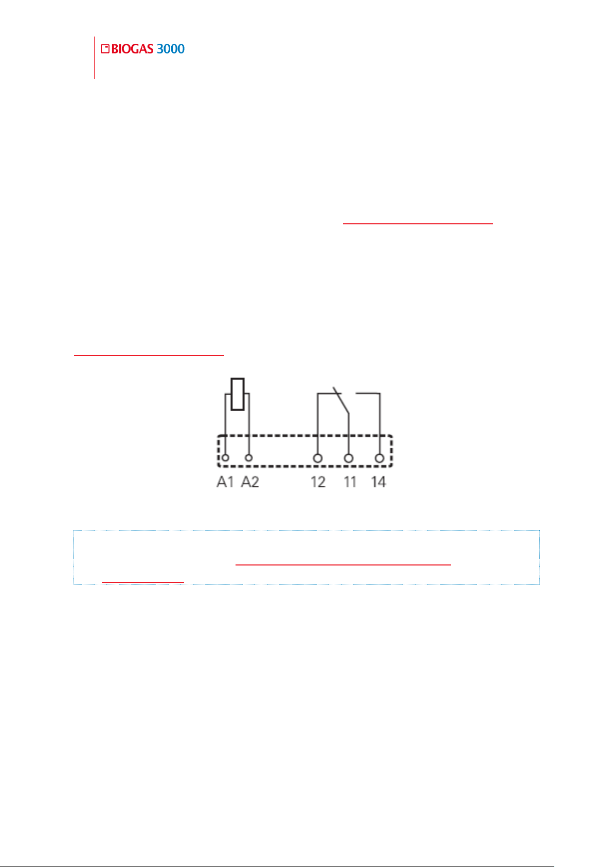
62
Operating Manual
Installation
OMBG3000 – Iss.01
© Copyright 2016
The system comes equipped with eight available relays. The relays are volt free
changeover contacts. The maximum rated voltage is 24Vdc.
When being used for alarms and fault notifications the relays are normally
energized (i.e. will de-energize when an alarm condition is triggered). This
means wiring across connections 11 and 12 during a notification will complete
the circuit and de-energize the relay. Refer to Wiring Diagram 4 - Relays for
further information.
When being used for sample point indication, catchpot notifications and air
purge notifications, the relays are normally de-energized (i.e. will energize
when the condition is active). This means wiring across connections 11 and 14
during a notification will complete the circuit and energize the relay. Refer to
Wiring Diagram 4 - Relays for further information.
Wiring Diagram 4 - Relays
Note: For terminal conductor sizes and cable insulation requirements,
please refer to section Cable Conductor Sizes and Insulation
Requirements.
Page 63

Operating Manual
Installation
63
© Copyright 2016
OMBG3000 – Rev1
Warning
The Modbus to Profibus converter module for the
BIOGAS 3000 is not ATEX or IECEx certified and must be
housed in a non-hazardous location or within a
flameproof enclosure. This is the responsibility of the
owner of the equipment.
The BIOGAS 3000 Modbus terminals must only be used
for standard Modbus communications; no other
connections must be made. Connections outside of this
could make the equipment unsafe resulting in a hazard
and invalidate the ATEX/IECEx certification.
4.13 Profibus Digital Output
The Profibus option for the BIOGAS 3000 is via a Modbus to Profibus converter
module. The converter is a Profibus slave module and acts as an interface
between the Modbus output of the BIOGAS 3000 and Profibus network.
Note: The Profibus module can be purchased as a post-sale accessory and
upgraded on site by the user; see LANDTEC part number BG3K.S3 in
BIOGAS 3000 Consumable Products.
For wiring to the Modbus terminals from the Profibus module, see section
Modbus Digital Output.
Configuration of the Profibus Module 4.13.1
The Profibus module node address is currently set to ‘02’. This can be adjusted,
if required, by using the small rotary switches underneath a cap found on the
front face of the module (see Figure 8 - Profibus module switch location). The
‘0’ is set using switch ‘A’ and the ‘2’ is set using switch ‘B’ (see Figure 9 -
Profibus module switch identification).
Note: The Profibus configuration GSD file required for setting up the
master Profibus communications is enclosed on the supplied CD.
Page 64
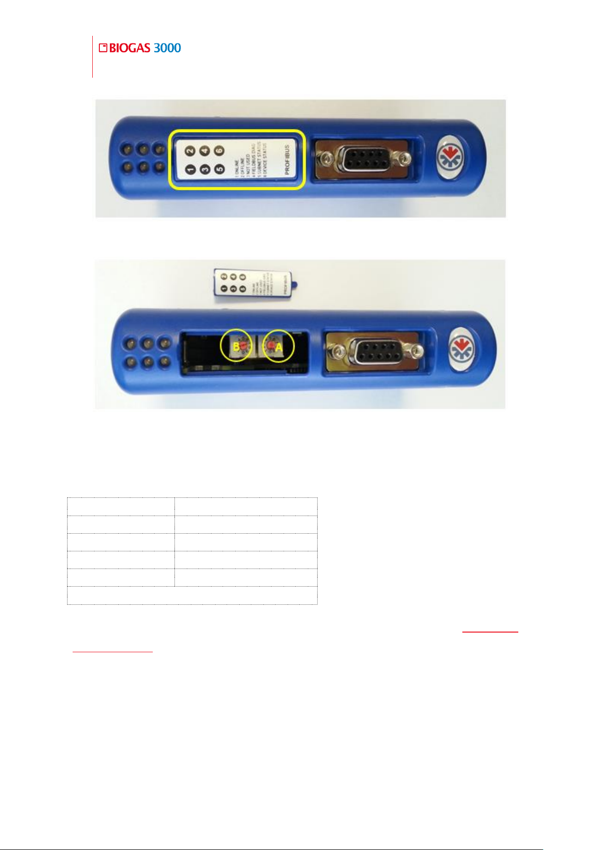
64
Operating Manual
Installation
OMBG3000 – Iss.01
© Copyright 2016
Node Address
1
Baud Rate
9600
Parity
Even
Stop Bits
1
Termination
On
The BIOGAS 3000 acts as a slave.
Figure 8 - Profibus module switch location
Figure 9 - Profibus module switch identification
In addition, the Modbus port on the BIOGAS 3000 must be configured as
followed:
To configure the Modbus port on the BIOGAS 3000, refer to section Configure
Modbus Slave in this operating manual.
Page 65

Operating Manual
Installation
65
© Copyright 2016
OMBG3000 – Rev1
Warning
Only a qualified person should make electrical
connections to the system.
Ensure the power is isolated.
Cable glands should meet the requirements of Cable
Gland Selection and Cord Anchorage.
Cable insulation and conductor sizes must meet the
requirements of Cable Conductor Sizes and Insulation
Requirements.
If using armored cable, the armor must not be used as
the main earth connection for the BIOGAS 3000. If
earthing of the armor is required, this must not be taken
from the BIOGAS 3000.
The power supply for the Modbus to Profibus converter
module must not be taken from the BIOGAS 3000. Using
the supply from the BIOGAS 3000 could make the
equipment unsafe resulting in a hazard and invalidate
the ATEX/IECEx certification.
All cables should be crimped with an appropriate
insulated ferrule for the size of the cable being used. In
addition, the cable insulation must be housed
adequately within the protective sheath of the ferrule.
Terminals that are wired should be tightened to a
minimum of 0.6Nm. Failure to tighten to this
requirement could make the equipment unsafe
resulting in a hazard and invalidate the ATEX/IECEx
certification.
The input voltage range to the BIOGAS 3000 Modbus
terminals must not exceed -7 to +12V and the current
must not exceed 83.3mA. Operating outside of this
range will invalidate the ATEX/IECEx certification.
Wiring the Profibus Module 4.13.2
Page 66
66
Operating Manual
Installation
OMBG3000 – Iss.01
© Copyright 2016
Terminal Colour
Wiring Information
Pair
Orange
Signal A (RS485) ‘+’
Pair one
Blue
Signal B (RS485) ‘-‘
White
Logic Ground (0V) ‘LG’
Pair two
Wire the outputs in accordance with Wiring Diagram 5 – Modbus to Profibus
converter module wiring. In addition, Wiring Diagram 2 – Modbus may also be
useful for wiring to the BIOGAS 3000 Modbus outputs.
For optimum performance, it is recommended that screened twisted pair cable
be used.
Note: For cable conductor sizes and cable insulation requirements, please
refer to section Cable Conductor Sizes and Insulation Requirements.
Note: If the distance between the BIOGAS 3000 and the Profibus
converter module is greater than 200m, it may be necessary to add a
termination resistor at the Profibus end to ensure noise-free
communications. In this case, place a 200ohms (0.25W) resistor across
the two data line terminals pins one and two on the Furse ESP SL06/I.
Note: For further information please contact our technical support team
at (800) 968-2026 or email [email protected].
When wiring the Modbus connections the twisted pairs must be as follows:
Page 67
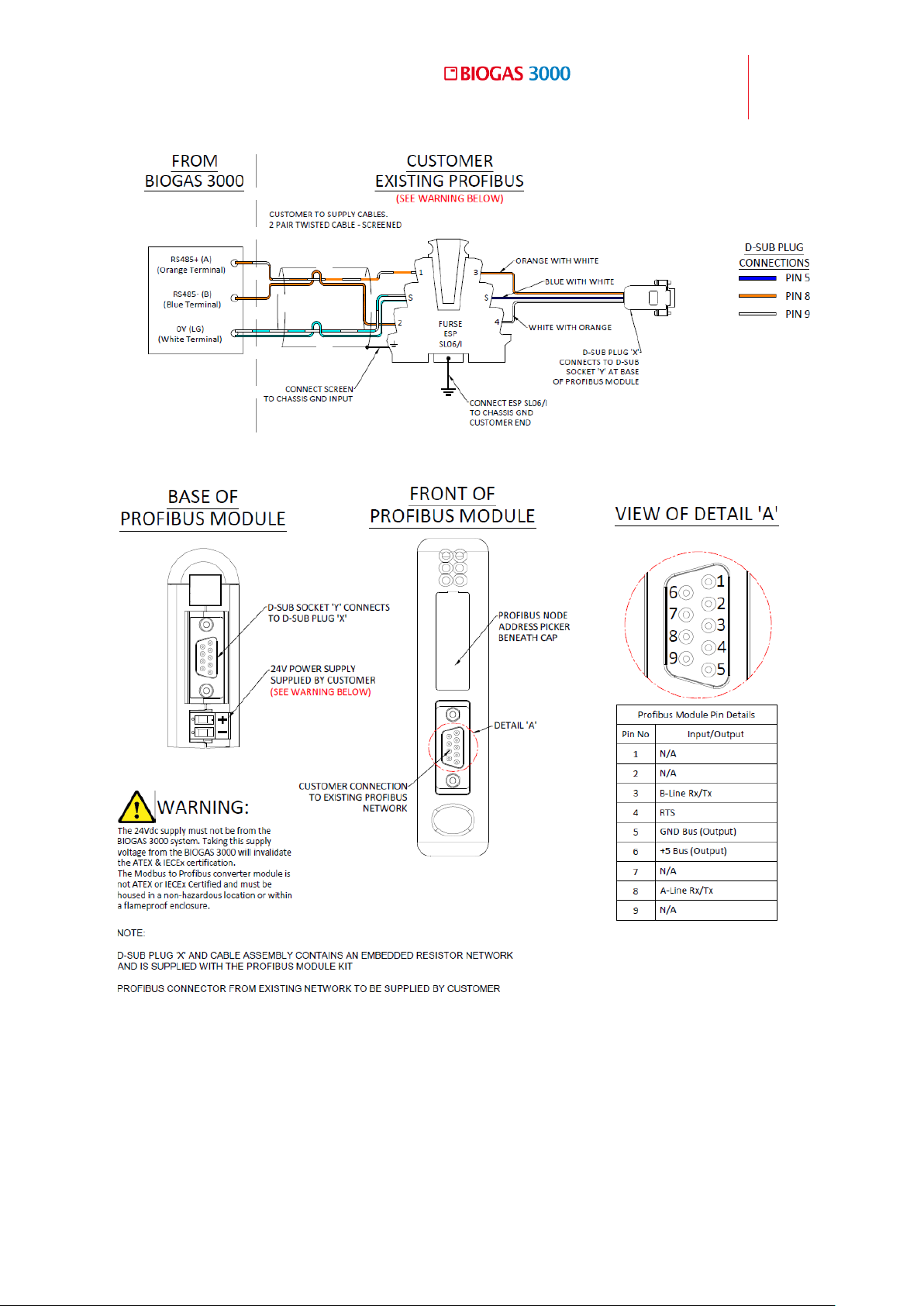
Operating Manual
Installation
67
© Copyright 2016
OMBG3000 – Rev1
Wiring Diagram 5 – Modbus to Profibus converter module wiring
Page 68
68
Operating Manual
Installation
OMBG3000 – Iss.01
© Copyright 2016
Module
Internal Name
Parameter
Example
0x0000
Sample Point 1 Last
Reading: Year
e.g. 0x07E0 (2016 dec) is 2016 or
High Byte 7x256 +Low Byte 0x224
0x0002
Sample Point 1 Last
Reading: Month
0x0004
Sample Point 1 Last
Reading: Day
0x0006
Sample Point 1 Last
Reading:
0x0008
Sample Point 1 Last
Reading:
0x000A
Sample Point 1 Last
Reading: Second
0x000C
Sample Point 1 Last
Reading: CH4 x 10
e.g. 0x0259 (601 dec) is 60.1% or
High Byte 2x256 +Low Byte 0x89
0x000E
Sample Point 1 Last
Reading: CO2 x 10
0x0010
Sample Point 1 Last
Reading: O2 x 10
0x0012
Sample Point 1 Last
Reading: Internal Cell
e.g. 0x03E8 (1000 dec) is
1000ppm or High Byte 3x256
+Low Byte 0x232
0x0014
Sample Point 1 Last
Reading:
0x0016
Sample Point 1 Last
Reading: Gas Flow
e.g. 0x0122 (290 dec) is
290ml/min or High Byte 1x256
+Low Byte 0x34
0x0018
Barometric Pressure
e.g. 0x03E1 (993 dec) is 993mbar
or High Byte 3x256 +Low Byte
0x225
0x001A
Sample Point 2 Last
Reading: Year
e.g. 0x07E0 (2016 dec) is 2016 or
High Byte 7x256 +Low Byte 0x224
0x001C
Sample Point 2 Last
Readable Parameters of the Profibus Module 4.13.3
The data available to the Profibus network is two (16-bit) words, each word
occupying two hex address locations as follows:
Page 69

Operating Manual
Installation
69
© Copyright 2016
OMBG3000 – Rev1
Reading: Month
0x001E
Sample Point 2 Last
Reading: Day
0x0020
Sample Point 2 Last
Reading: Hour
0x0022
Sample Point 2 Last
Reading: Minute
0x0024
Sample Point 2 Last
Reading: Second
0x0026
Sample Point 2 Last
Reading: CH4 x 10
e.g. 0x0259 (601 dec) is 60.1% or
High Byte 2x256 +Low Byte 0x89
0x0028
Sample Point 2 Last
Reading: CO2 x 10
0x002A
Sample Point 2 Last
Reading: O2 x 10
0x002C
Sample Point 2 Last
Reading: Internal Cell
e.g. 0x03E8 (1000 dec) is
1000ppm or High Byte 3x256
+Low Byte 0x232
0x002E
Sample Point 2 Last
Reading: External cell
0x0030
Sample Point 2 Last
Reading: Gas Flow
e.g. 0x0122 (290 dec) is
290ml/min or High Byte 1x256
+Low Byte 0x34
0x0032
Sample Point 3 Last
Reading: Year
e.g. 0x07E0 (2016 dec) is 2016 or
High Byte 7x256 +Low Byte 0x224
0x0034
Sample Point 3 Last
Reading: Month
0x0036
Sample Point 3 Last
Reading: Day
0x0038
Sample Point 3 Last
Reading: Hour
0x003A
Sample Point 3 Last
Reading: Minute
0x003C
Sample Point 3 Last
Reading: Second
0x003E
Sample Point 3 Last
Reading: CH4 x 10
e.g. 0x0259 (601 dec) is 60.1% or
High Byte 2x256 +Low Byte 0x89
0x0040
Sample Point 3 Last
Page 70

70
Operating Manual
Installation
OMBG3000 – Iss.01
© Copyright 2016
Reading: CO2 x 10
0x0042
Sample Point 3 Last
Reading: O2 x 10
0x0044
Sample Point 3 Last
Reading: Internal Cell
e.g. 0x03E8 (1000 dec) is
1000ppm or High Byte 3x256
+Low Byte 0x232
0x0046
Sample Point 3 Last
Reading: External cell
0x0048
Sample Point 3 Last
Reading: Gas Flow
e.g. 0x0122 (290 dec) is
290ml/min or High Byte 1x256
+Low Byte 0x34
0x004A
Sample Point 4 Last
Reading: Year
e.g. 0x07E0 (2016 dec) is 2016 or
High Byte 7x256 +Low Byte 0x224
0x004C
Sample Point 4 Last
Reading: Month
0x004E
Sample Point 4 Last
Reading: Day
0x0050
Sample Point 4 Last
Reading: Hour
0x0052
Sample Point 4 Last
Reading: Minute
0x0054
Sample Point 4 Last
Reading: Second
0x0056
Sample Point 4 Last
Reading: CH4 x 10
e.g. 0x0259 (601 dec) is 60.1% or
High Byte 2x256 +Low Byte 0x89
0x0058
Sample Point 4 Last
Reading: CO2 x 10
0x005A
Sample Point 4 Last
Reading: O2 x 10
0x005C
Sample Point 4 Last
Reading: Internal Cell
e.g. 0x03E8 (1000 dec) is
1000ppm or High Byte 3x256
+Low Byte 0x232
0x005E
Sample Point 4 Last
Reading: External cell
0x0060
Sample Point 4 Last
Reading: Gas Flow
e.g. 0x0122 (290 dec) is
290ml/min or High Byte 1x256
+Low Byte 0x34
0x0062
Alarm 1
0= No Alarm,
Page 71

Operating Manual
Installation
71
© Copyright 2016
OMBG3000 – Rev1
0x0064
Alarm 2
1=Triggered,
0x0066
Alarm 3
2=Triggered and in recovery zone
0x0068
Alarm 4
4 = Latched
0x006A
Alarm 5
8 = Muted
0x006C
Alarm 6
9 = Triggered alarm and muted
0x006E
Alarm 7
A = Recovering alarm and muted
0x0080
Current sample Point
1 to 4
The Profibus module updates the readings from the BIOGAS 3000 every 2.5
seconds.
Successful communication between the Modbus output and the Profibus
module is indicated by the subnet status light ‘5’ on the module showing
green. If for any reason the communications is intermittent or fails, the light
flashes red or is permanently red, and the value being read is cleared to zero
and not frozen with a previous value. Monitoring for an example the year,
month and day for non-zero values will gain confidence that communications is
ongoing.
Page 72
72
Operating Manual
Installation
OMBG3000 – Iss.01
© Copyright 2016
Warning
The Modbus to Profinet converter module for the
BIOGAS 3000 is not ATEX or IECEx certified and must be
housed in a non-hazardous location or within a
flameproof enclosure. This is the responsibility of the
owner of the equipment.
The BIOGAS 3000 Modbus terminals must only be used
for standard Modbus communications; no other
connections must be made. Connections outside of this
could make the equipment unsafe resulting in a hazard
and invalidate the ATEX/IECEx certification.
Node Address
1
Baud Rate
9600
Parity
Even
Stop Bits
1
Termination
On
The BIOGAS 3000 acts as a slave.
4.14 Profinet Digital Output
The Profinet option for the BIOGAS 3000 is via a Modbus to Profinet converter
module. The converter is a Profinet slave module and acts as an interface
between the Modbus output of the BIOGAS 3000 and Profinet network.
Note: The Profinet module can be purchased as a post-sale accessory and
upgraded on site by the user, see LANDTEC part number BG3K.S4 in
BIOGAS 3000 Consumable Products.
For wiring to the Modbus terminals from the Profibus module, see section
Modbus Digital Output.
Configuration of the Profinet Module 4.14.1
The Profinet module can be configured using the GSDML file supplied on the
enclosed CD. Follow the instructions on the supplied installation sheet to
configure the module for the Profinet sub-network.
In addition, the Modbus port on the BIOGAS 3000 must be configured as
followed:
Page 73

Operating Manual
Installation
73
© Copyright 2016
OMBG3000 – Rev1
Warning
Only a qualified person should make electrical
connections to the system.
Ensure the power is isolated.
Cable glands should meet the requirements of Cable
Gland Selection and Cord Anchorage.
Cable insulation and conductor sizes must meet the
requirements of Cable Conductor Sizes and Insulation
Requirements.
If using armored cable, the armor must not be used as
the main earth connection for the BIOGAS 3000. If
earthing of the armor is required, this must not be taken
from the BIOGAS 3000.
The power supply for the Modbus to Profinet converter
module must not be taken from the BIOGAS 3000. Using
the supply from the BIOGAS 3000 could make the
equipment unsafe resulting in a hazard and invalidate
the ATEX/IECEx certification.
All cables should be crimped with an appropriate
insulated ferrule for the size of the cable being used. In
addition, the cable insulation must be housed
adequately within the protective sheath of the ferrule.
Terminals that are wired should be tightened to a
minimum of 0.6Nm. Failure to tighten to this
requirement could make the equipment unsafe
resulting in a hazard and invalidate the ATEX/IECEx
certification.
The input voltage range to the BIOGAS 3000 Modbus
terminals must not exceed -7 to +12V and the current
To configure the Modbus port on the BIOGAS 3000, refer to section Configure
Modbus Slave in this operating manual.
Wiring the Profinet Module 4.14.2
Page 74
74
Operating Manual
Installation
OMBG3000 – Iss.01
© Copyright 2016
Terminal Colour
Wiring Information
Pair
Orange
Signal A (RS485) ‘+’
Pair one
Blue
Signal B (RS485) ‘-‘
White
Logic Ground (0V) ‘LG’
Pair two
must not exceed 83.3mA. Operating outside of this
range will invalidate the ATEX/IECEx certification.
Wire the outputs in accordance with Wiring Diagram 6 - Modbus to Profinet
converter module wiring. In addition, Wiring Diagram 2 – Modbus may also be
useful for wiring to the BIOGAS 3000 Modbus outputs.
For optimum performance, it is recommended that screened twisted pair cable
be used.
Note: For cable conductor sizes and cable insulation requirements, please
refer to section Cable Conductor Sizes and Insulation Requirements.
Note: If the distance between the BIOGAS 3000 and the Profinet
converter module is greater than 200m, it may be necessary to add a
termination resistor at the Profinet end to ensure noise-free
communications. In this case, place a 200ohms (0.25W) resistor across
the two data line terminals pins one and two on the Furse ESP SL06/I.
Note: For further information please contact our technical support team
at (800) 968-2026 or email [email protected].
When wiring the Modbus connections the twisted pairs must be as follows:
Page 75
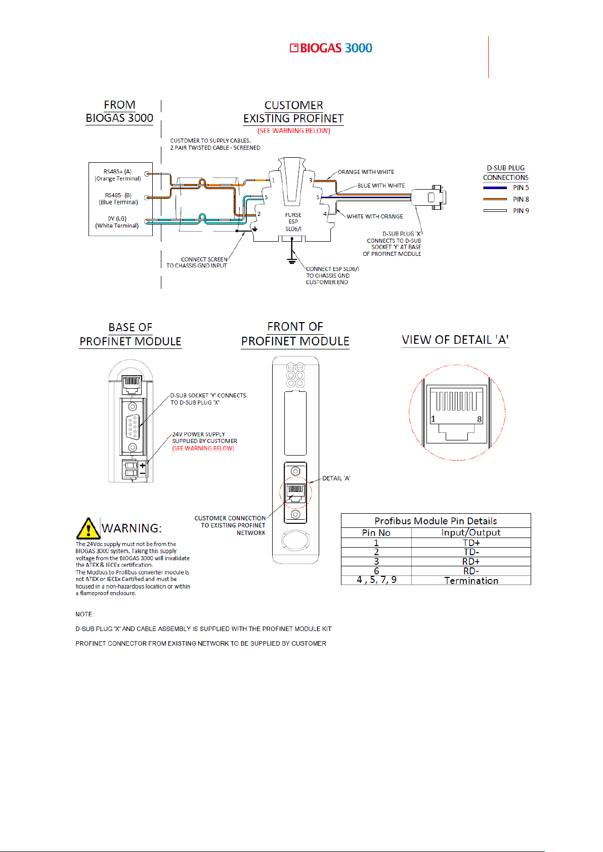
Operating Manual
Installation
75
© Copyright 2016
OMBG3000 – Rev1
Wiring Diagram 6 - Modbus to Profinet converter module wiring
Page 76
76
Operating Manual
Installation
OMBG3000 – Iss.01
© Copyright 2016
Module
Internal Name
Parameter
Example
0x0000
Sample Point 1 Last
Reading: Year
e.g. 0x07E0 (2016 dec) is 2016 or
High Byte 7x256 +Low Byte 0x224
0x0002
Sample Point 1 Last
Reading: Month
0x0004
Sample Point 1 Last
Reading: Day
0x0006
Sample Point 1 Last
Reading:
0x0008
Sample Point 1 Last
Reading:
0x000A
Sample Point 1 Last
Reading: Second
0x000C
Sample Point 1 Last
Reading: CH4 x 10
e.g. 0x0259 (601 dec) is 60.1% or
High Byte 2x256 +Low Byte 0x89
0x000E
Sample Point 1 Last
Reading: CO2 x 10
0x0010
Sample Point 1 Last
Reading: O2 x 10
0x0012
Sample Point 1 Last
Reading: Internal Cell
e.g. 0x03E8 (1000 dec) is
1000ppm or High Byte 3x256
+Low Byte 0x232
0x0014
Sample Point 1 Last
Reading:
0x0016
Sample Point 1 Last
Reading: Gas Flow
e.g. 0x0122 (290 dec) is
290ml/min or High Byte 1x256
+Low Byte 0x34
0x0018
Barometric Pressure
e.g. 0x03E1 (993 dec) is 993mbar
or High Byte 3x256 +Low Byte
0x225
0x001A
Sample Point 2 Last
Reading: Year
e.g. 0x07E0 (2016 dec) is 2016 or
High Byte 7x256 +Low Byte 0x224
0x001C
Sample Point 2 Last
Readable Parameters of the Profinet Module 4.14.3
The data available to the Profinet network is two (16-bit) words, each word
occupying two hex address locations as follows:
Page 77

Operating Manual
Installation
77
© Copyright 2016
OMBG3000 – Rev1
Reading: Month
0x001E
Sample Point 2 Last
Reading: Day
0x0020
Sample Point 2 Last
Reading: Hour
0x0022
Sample Point 2 Last
Reading: Minute
0x0024
Sample Point 2 Last
Reading: Second
0x0026
Sample Point 2 Last
Reading: CH4 x 10
e.g. 0x0259 (601 dec) is 60.1% or
High Byte 2x256 +Low Byte 0x89
0x0028
Sample Point 2 Last
Reading: CO2 x 10
0x002A
Sample Point 2 Last
Reading: O2 x 10
0x002C
Sample Point 2 Last
Reading: Internal Cell
e.g. 0x03E8 (1000 dec) is
1000ppm or High Byte 3x256
+Low Byte 0x232
0x002E
Sample Point 2 Last
Reading: External cell
0x0030
Sample Point 2 Last
Reading: Gas Flow
e.g. 0x0122 (290 dec) is
290ml/min or High Byte 1x256
+Low Byte 0x34
0x0032
Sample Point 3 Last
Reading: Year
e.g. 0x07E0 (2016 dec) is 2016 or
High Byte 7x256 +Low Byte 0x224
0x0034
Sample Point 3 Last
Reading: Month
0x0036
Sample Point 3 Last
Reading: Day
0x0038
Sample Point 3 Last
Reading: Hour
0x003A
Sample Point 3 Last
Reading: Minute
0x003C
Sample Point 3 Last
Reading: Second
0x003E
Sample Point 3 Last
Reading: CH4 x 10
e.g. 0x0259 (601 dec) is 60.1% or
High Byte 2x256 +Low Byte 0x89
0x0040
Sample Point 3 Last
Page 78

78
Operating Manual
Installation
OMBG3000 – Iss.01
© Copyright 2016
Reading: CO2 x 10
0x0042
Sample Point 3 Last
Reading: O2 x 10
0x0044
Sample Point 3 Last
Reading: Internal Cell
e.g. 0x03E8 (1000 dec) is
1000ppm or High Byte 3x256
+Low Byte 0x232
0x0046
Sample Point 3 Last
Reading: External cell
0x0048
Sample Point 3 Last
Reading: Gas Flow
e.g. 0x0122 (290 dec) is
290ml/min or High Byte 1x256
+Low Byte 0x34
0x004A
Sample Point 4 Last
Reading: Year
e.g. 0x07E0 (2016 dec) is 2016 or
High Byte 7x256 +Low Byte 0x224
0x004C
Sample Point 4 Last
Reading: Month
0x004E
Sample Point 4 Last
Reading: Day
0x0050
Sample Point 4 Last
Reading: Hour
0x0052
Sample Point 4 Last
Reading: Minute
0x0054
Sample Point 4 Last
Reading: Second
0x0056
Sample Point 4 Last
Reading: CH4 x 10
e.g. 0x0259 (601 dec) is 60.1% or
High Byte 2x256 +Low Byte 0x89
0x0058
Sample Point 4 Last
Reading: CO2 x 10
0x005A
Sample Point 4 Last
Reading: O2 x 10
0x005C
Sample Point 4 Last
Reading: Internal Cell
e.g. 0x03E8 (1000 dec) is
1000ppm or High Byte 3x256
+Low Byte 0x232
0x005E
Sample Point 4 Last
Reading: External cell
0x0060
Sample Point 4 Last
Reading: Gas Flow
e.g. 0x0122 (290 dec) is
290ml/min or High Byte 1x256
+Low Byte 0x34
0x0062
Alarm 1
0= No Alarm,
Page 79
Operating Manual
Installation
79
© Copyright 2016
OMBG3000 – Rev1
0x0064
Alarm 2
1=Triggered,
0x0066
Alarm 3
2=Triggered and in recovery zone
0x0068
Alarm 4
4 = Latched
0x006A
Alarm 5
8 = Muted
0x006C
Alarm 6
9 = Triggered alarm and muted
0x006E
Alarm 7
A = Recovering alarm and muted
0x0080
Current sample Point
1 to 4
The Profinet module updates the readings from the BIOGAS 3000 every 2.5
seconds.
Successful communication between the Modbus output and the Profinet
module is indicated by the subnet status light ‘5’ on the module showing
green. If for any reason the communications is intermittent or fails, the light
flashes red or is permanently red, and the value being read is cleared to zero
and not frozen with a previous value. Monitoring for an example the year,
month and day for non-zero values will gain confidence that communications is
ongoing.
4.15 Heater Option
If purchased at the point of sale, the equipment will be fitted with a 100W
heater (suitable for the relevant mains input voltage), control thermostat, and
enclosure insulation. The thermostat is pre-set to 15°C (59⁰F) and cannot be
adjusted.
Page 80

80
Operating Manual
Installation
OMBG3000 – Iss.01
© Copyright 2016
4.16 Final Checks
Ensure all gas connections to the system are leak free – refer to section
Pressure Test of this operating manual for instructions on how to
perform this.
Ensure the gas inlet and gas outlet ball valves are open (refer to
annotation 12 on
Figure 2 - BIOGAS 3000 internal components) these must be in the
vertical position.
Ensure the drain ball valve, if fitted, is closed (see annotation 9 on
Figure 2 - BIOGAS 3000 internal components), this must be in the
horizontal position.
Ensure the calibration ball valve is closed (see annotation 10 on
Figure 2 - BIOGAS 3000 internal components), this must be in the
vertical position.
Turn the power on to the system. Within one minute of power being
applied, the module will turn on and display the BIOGAS 3000 logo,
shortly followed by the ‘system self-test’ screen (see Screen 2 - System
Self-Test).
The first time the module is started after the self-test has successfully
completed, the ‘first time run set-up wizard’ will begin – please refer to
section First Time Run Set-up in this manual for details of this process.
It is strongly recommended that a known concentration of gas be
passed through the system to ensure that it still reading correctly
following installation. Refer to the Gas Check and Calibration section of
this operating manual for further information on this process.
Note: For further information please contact our technical support team at
(800) 968-2026 or email [email protected].
Page 81
Operating Manual
General Operating Instructions
81
© Copyright 2016
OMBG3000 – Rev1
Warning
Do not open when an explosive atmosphere is present.
General Operating Instructions 5
5.1 Switching the BIOGAS 3000 System On
1) The module will automatically turn on when power to the system is
switched on. If this does not happen, refer to the Problem Solving section
of this operating manual.
Note: It can take up to one minute for the BIOGAS 3000 module to power
on. If it does not turn on at the point power to the system is applied,
please wait one minute before pressing any keys on the module.
2) If the power on is successful, the ‘LANDTEC BIOGAS 3000’ logo will appear
on screen and then the ‘System Self-Test’ will commence.
Screen 1 - Power on
5.2 Self-Test
Note: If the system has an invalid time and date setting, the operator will
be prompted to correct this before a self-test commences.
When switched on the module will perform a pre-determined self-test
sequence taking approximately sixty seconds. During the self-test, the
Page 82
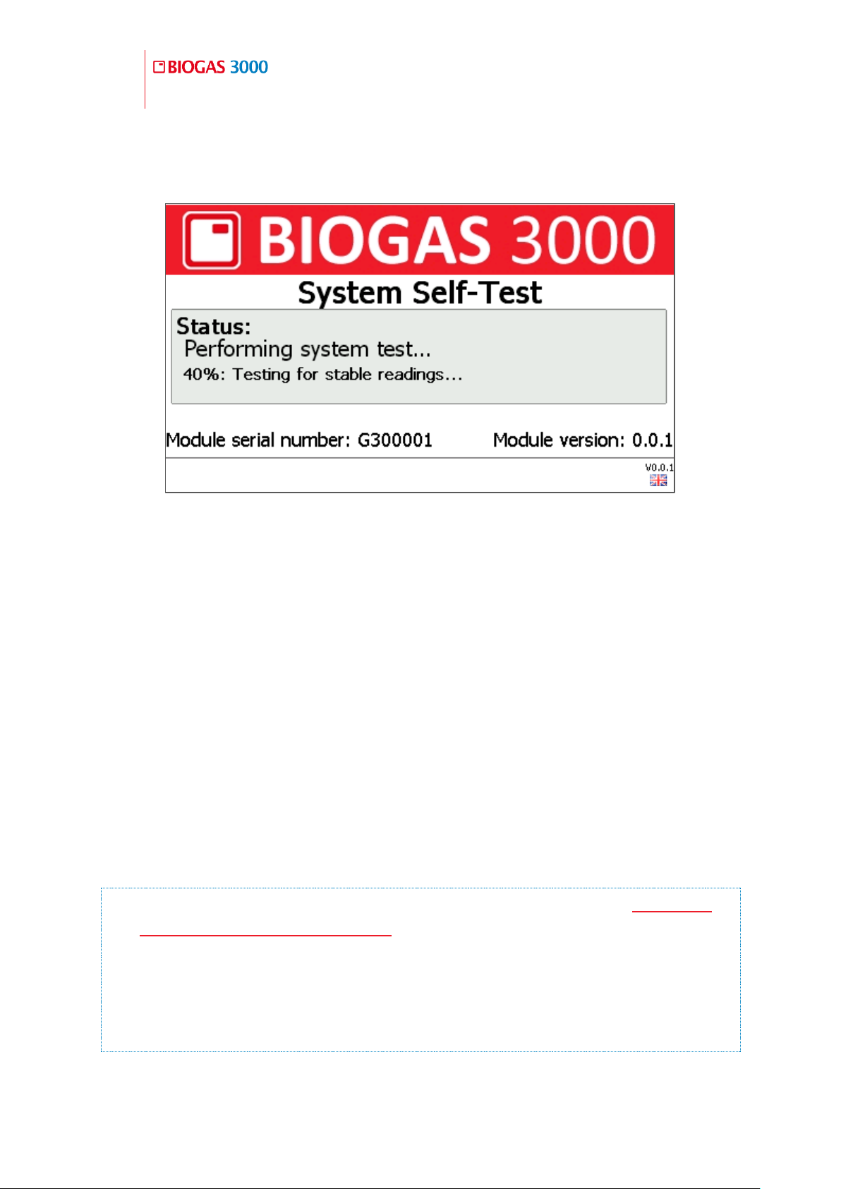
82
Operating Manual
General Operating Instructions
OMBG3000 – Iss.01
© Copyright 2016
percentage complete is shown and remains on screen until the self-test is
completed.
Screen 2 - System Self-Test
During this time, many of the system’s functions are tested, including:
Testing of the CH4, CO2, O2, reference, barometer, internal cell,
external cell, and transducers is performed continuously over a short
period to check for faults and instability
The pump is switched on and the system checked for blockages
The next service due date is checked
Valid communications to the Interface PCB is checked
Test whether the ‘first time run set-up’ is required.
If no faults are found, then the first time set-up or monitoring will begin.
Note: After completion, if any non-critical failures occur then Screen 3 -
Self-test finished with warnings screen is shown.
Note: If the fault is ‘service overdue’ or a channel warning (non-critical)
then the user can continue to the next stage by pressing the right soft key
‘Continue’. The BIOGAS 3000 will continue automatically after thirty
seconds if continue is not pressed.
Page 83
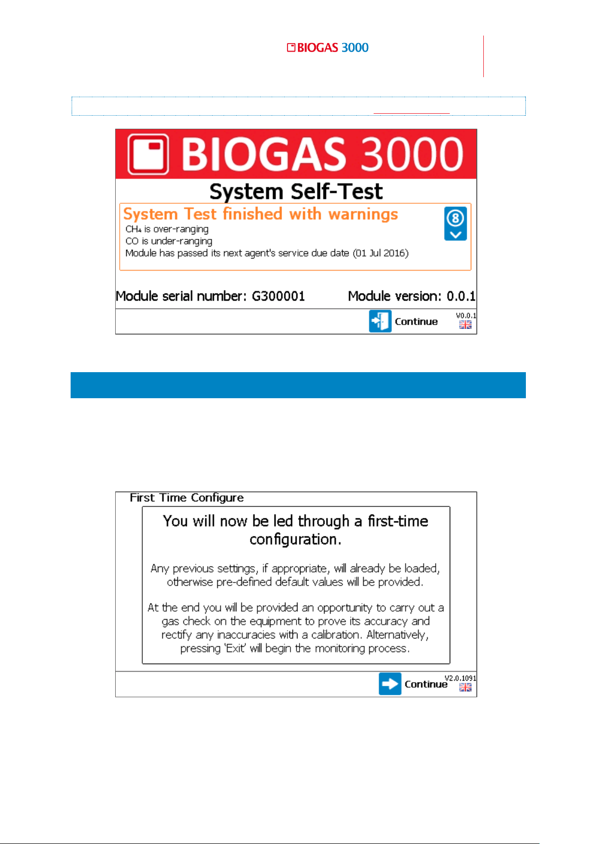
Operating Manual
General Operating Instructions
83
© Copyright 2016
OMBG3000 – Rev1
Note: If any critical faults occur, refer to section Critical Faults.
Screen 3 - Self-test finished with warnings
5.3 First Time Run Set-up
1) When switching on the module for the first time the system will detect the
first time run conditions and run set-up mode. The BIOGAS 3000 is
designed to be fully configurable by the end-user without LANDTEC
support or configuration.
2) Press the right soft key to ‘Continue’.
Screen 4 - First time run set-up
Page 84

84
Operating Manual
General Operating Instructions
OMBG3000 – Iss.01
© Copyright 2016
3) Configure the time that the daily air purge will commence. For more
information on how to do this, refer to section Daily Air Purge.
Note: This option will only be present on BG3KE variants.
4) Configure the sampling options for the various sample points. For more
information on how to do this, refer to section Sample Times.
Note: On a BG3KE variant without an external sensor, this option is not
present.
Note: On a BG3KE variant with an external sensor, this screen will be
specifically for the external sensor sampling option only as the rest of the
system will measure continuously.
5) Customise the relay configuration. For more information on how to do
this, refer to section Configure Relays.
6) Configure alarms (if set during the relay configuration option). For more
information on how to do this, refer to section Configure Alarms.
7) Configure Modbus slave (if being used). For more information on how to
do this, refer to section Configure Modbus Slave.
8) Configure analogue outputs (if being used). For more information on how
to do this, refer to section Configure Analog Outputs.
9) Define whether an administrator passcode is required on the system. For
more information on how to do this, refer to section Admin Passcode.
10) Once the first time run set-up is complete, you will arrive at Screen 28 -
Gas Check. To perform this, refer to section Gas Check and Calibration. To
skip and begin monitoring, press the right soft key to ‘Exit’ (not
recommended).
Page 85
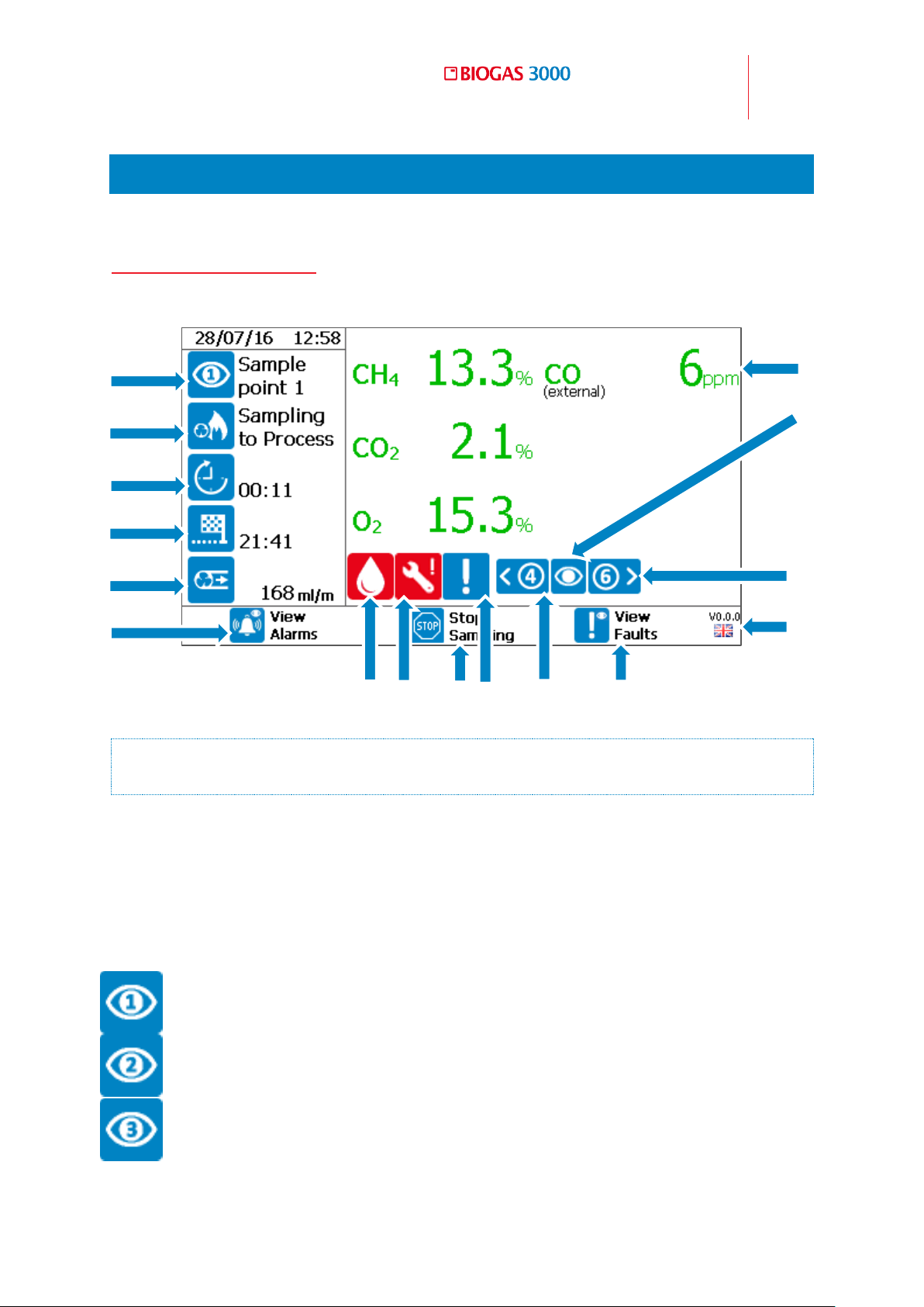
Operating Manual
General Operating Instructions
85
© Copyright 2016
OMBG3000 – Rev1
Sample point 1
Sample point 2
Sample point 3
2 3 4 5 6
7
8
9
10
12
16
15
14
13
17
11
5.4 Gas Readings Screen
Screen 5 - Gas readings is considered the normal operating screen and all
options are carried out from this starting point:
Screen 5 - Gas readings
Note: The data shown on this display will be dependent on the system
variant and the option(s) that was selected at the point of sale.
1. Time and date
Displays the time and date and is continuously updated.
2. Sample point status
This indicates to the user the current sample point being monitored.
Page 86
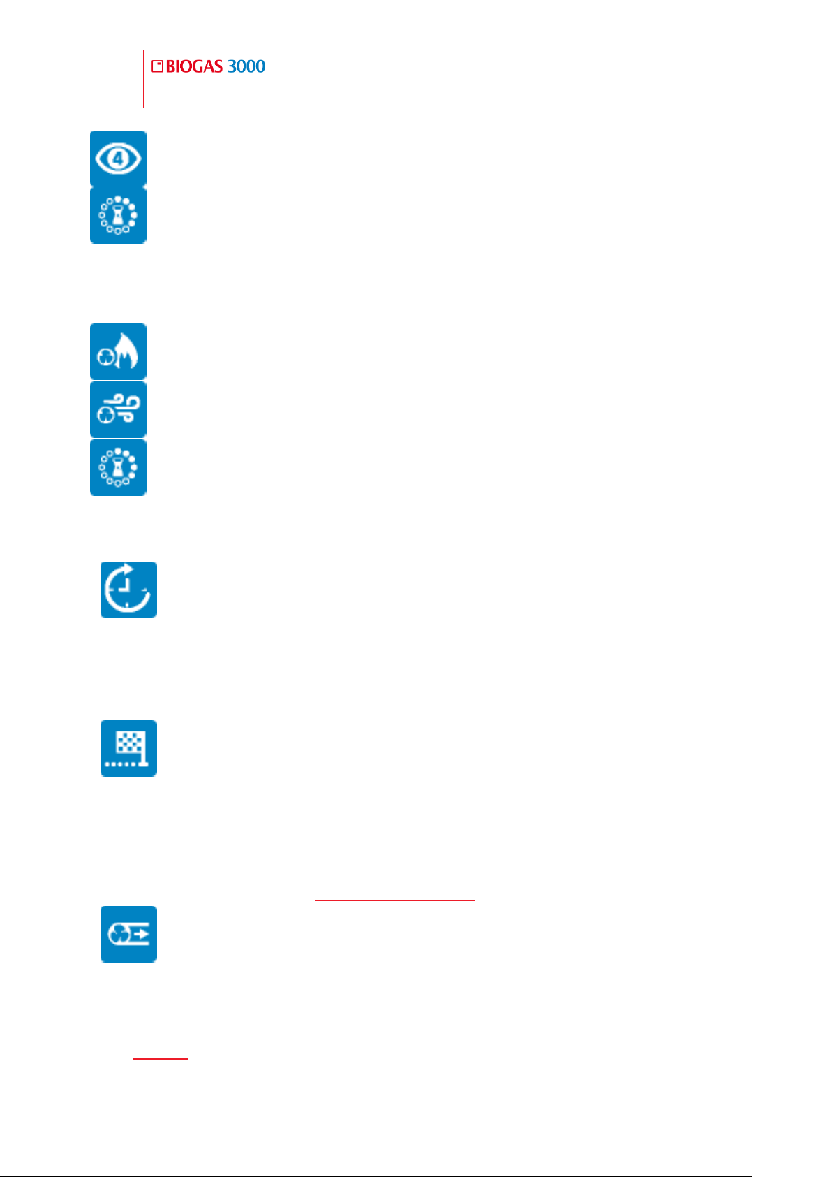
86
Operating Manual
General Operating Instructions
OMBG3000 – Iss.01
© Copyright 2016
Sample point 4
Idle – waiting for next cycle to begin.
Sampling from sample point
System air purge following sample
Idle – waiting for next cycle to begin
3. Current operation
Details the current operation for the sample point and cycle:
4. Operation time remaining
This is the time remaining for the current operation.
5. Cycle time remaining
This is the time remaining for the complete cycle. When it counts to zero, the
next cycle will commence, thus starting at sample point 1 again.
6. Pump flow rate
This is the pump flow rate in ml/min. If this drops below 75ml/min, the reading
will have an amber background and the system will flow fail and stop sampling
after fifteen seconds – see Low Flow / Flow Fail for more information.
7. View alarms
Accessed using the left soft key, it takes the user to the alarm summary screen.
See Alarms section.
Page 87
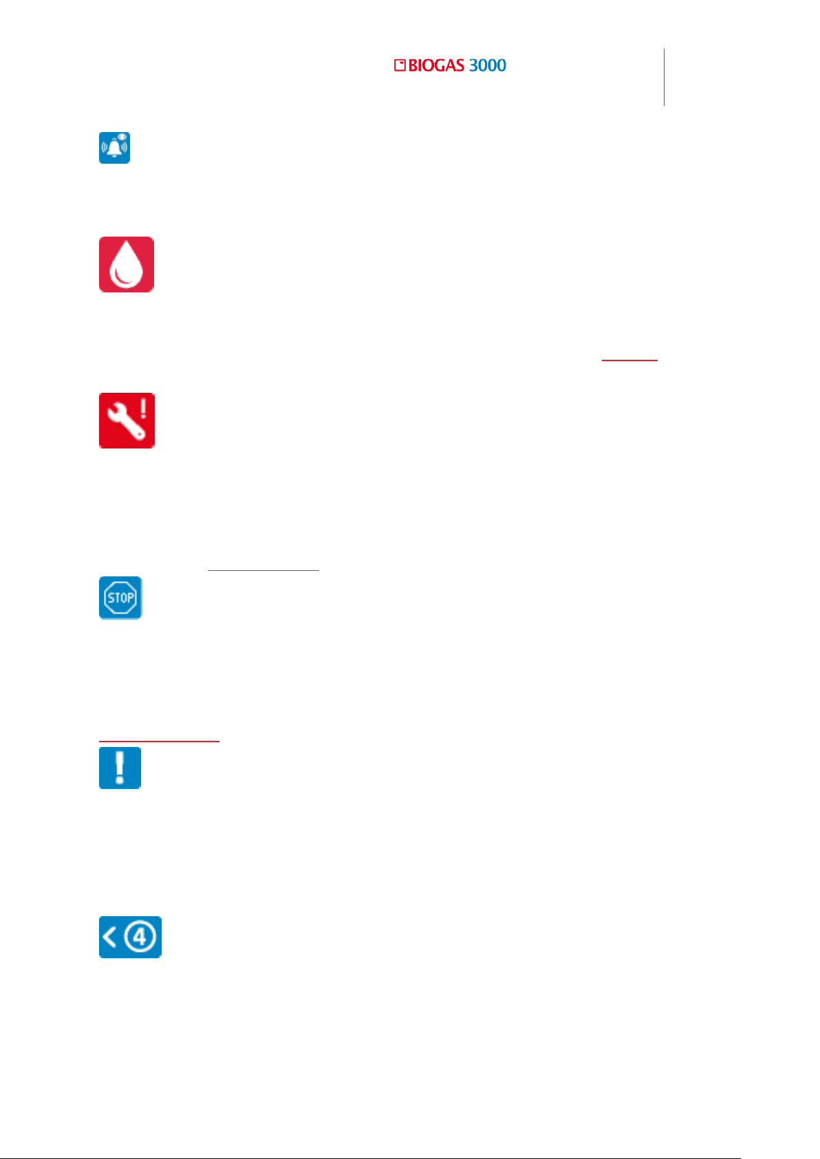
Operating Manual
General Operating Instructions
87
© Copyright 2016
OMBG3000 – Rev1
8. Catchpot full icon
Indicates to the user that there is liquid in the catchpot and it needs emptying.
9. Service icon
An indication to the user that the module is due for service. See Service
section.
10. Stop sampling
Press the middle soft key to stop the sample process and freeze the outputs at
their last known value. This can be useful when maintenance on site may be
required. See Stop Sampling section.
11. Non-critical fault warning
This icon displays when there is a non-critical fault present on the system. A
non-critical fault is a fault that will not stop the system from functioning. See
Fault Detection for more information.
12. Scroll left
Use key ‘4’ to scroll through the previously stored gas readings. This will
display the readings in memory for the data being output for the particular
sample point shown.
13. View faults
Press the right soft key to view the faults summary screen.
Page 88
88
Operating Manual
General Operating Instructions
OMBG3000 – Iss.01
© Copyright 2016
14. Module firmware/language
Displays the firmware version of the module and current language setting.
15. Scroll right
Use key ‘6’ to scroll through previously stored gas readings. This will display
the readings in memory for the data being output for the particular sample
point shown.
16. Current view
Indicates which sample point the data on screen is representing with a number
in the eye. These icons are the same as the sample point status icons. An eye
without a number represents live readings for the current sample point being
monitored.
17. Gas readings
Displays the readings for the gases available. Green text indicates the reading
is live. Blue text indicates the reading is a stored reading against the sample
point. If the gas channel is an external cell, “(external)” will be shown below
the gas name.
5.5 Alarms
Notification 5.5.1
Note: For information on how to set alarms, please refer to section
Configure Alarms.
When an alarm condition has been met, the alarming channel will become
highlighted with a bell icon and the ‘View Alarm’ soft key becomes red. An
example screen is shown below of a channel with an active alarm.
Page 89
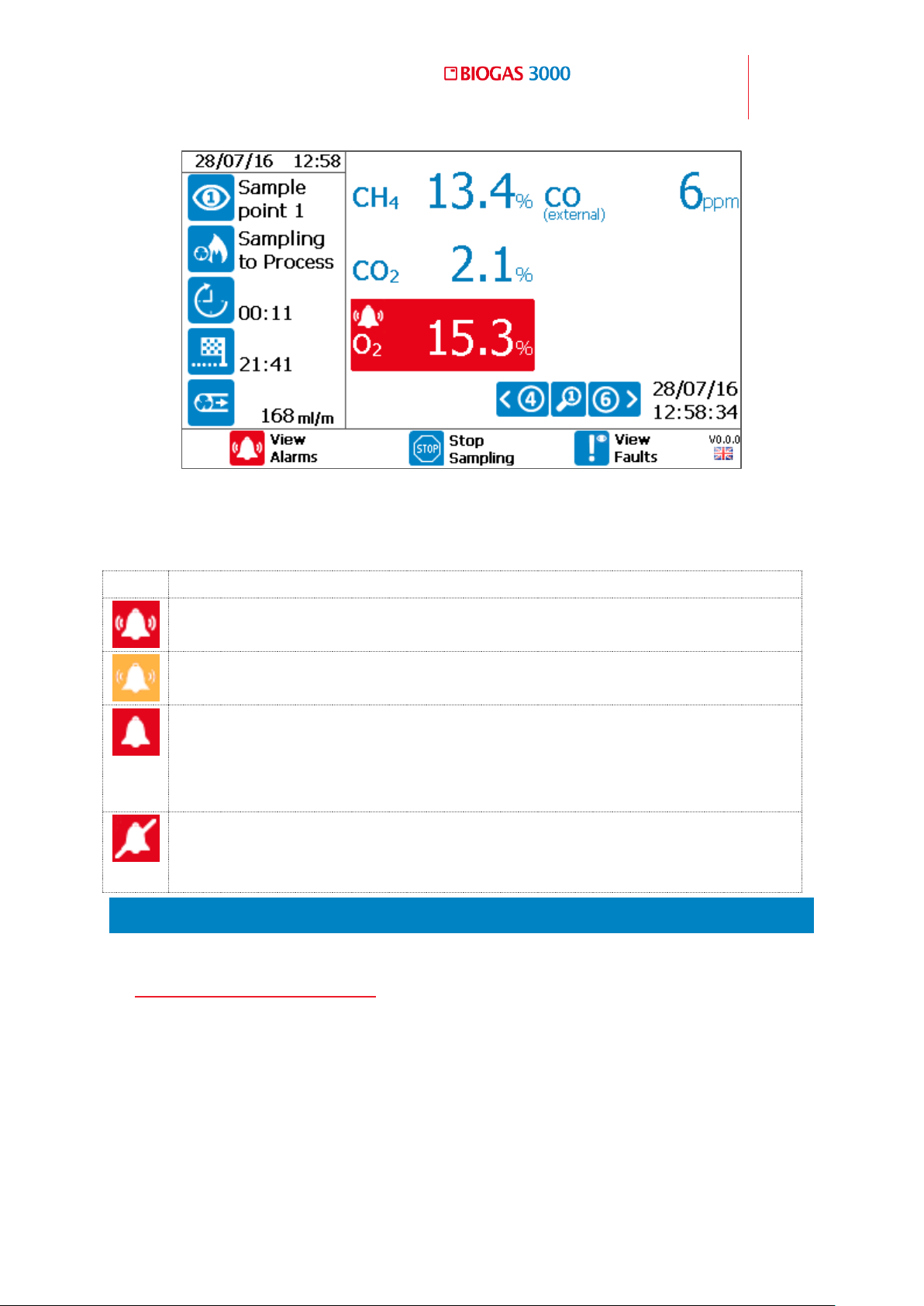
Operating Manual
General Operating Instructions
89
© Copyright 2016
OMBG3000 – Rev1
Icon
Definition
The alarm is active and the associated relay has been de-energized.
The alarm is active but the channel is within its recovery zone. The
associated relay remains de-energized until the recovery value is met.
This is the latched alarm indicator. This indicates a channel has
alarmed and recovered. During this notification, the relay remains deenergized until the alarm notification has been acknowledged by the
operator.
The alarm has been silenced by the operator and the associated relay
is energized. The alarm condition on the system remains active in the
background until the recovery condition is met.
Screen 6 - Alarm notification
The following notifications are available on the BIOGAS 3000:
Viewing Alarms 5.5.2
To view an alarm, from the ‘Gas Readings Screen’ press the left soft key to go
to Screen 7 - Alarms summary:
Page 90
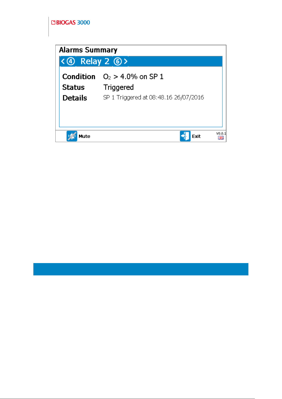
90
Operating Manual
General Operating Instructions
OMBG3000 – Iss.01
© Copyright 2016
Screen 7 - Alarms summary
This screen will detail all alarm conditions set by the operator. It will detail the
condition for the alarm to trigger, the status (inactive, triggered, latched, or
recovering), the time and date of the alarm, and the associated relay.
Pressing key ‘4’ and key ‘6’ scrolls the user through the relays available for
alarms. This will also summarize inactive alarms.
Pressing the left soft key (‘Mute’) on an active alarm will disable the alarm and
re-energizes the associated relay until the condition is cleared.
Pressing the left soft key (‘Clear Latch’) on a latched alarm will unlatch the
alarm, clearing its status and re-energizes the associated relay.
5.6 Stop Sampling
From the ‘Gas Readings Screen’, pressing the middle soft key will ‘Stop
Sampling’. At this point, the sampling process is stopped, all solenoid valves
are closed, and the outputs are frozen at their last known value. The following
screen will be presented to the user:
Page 91
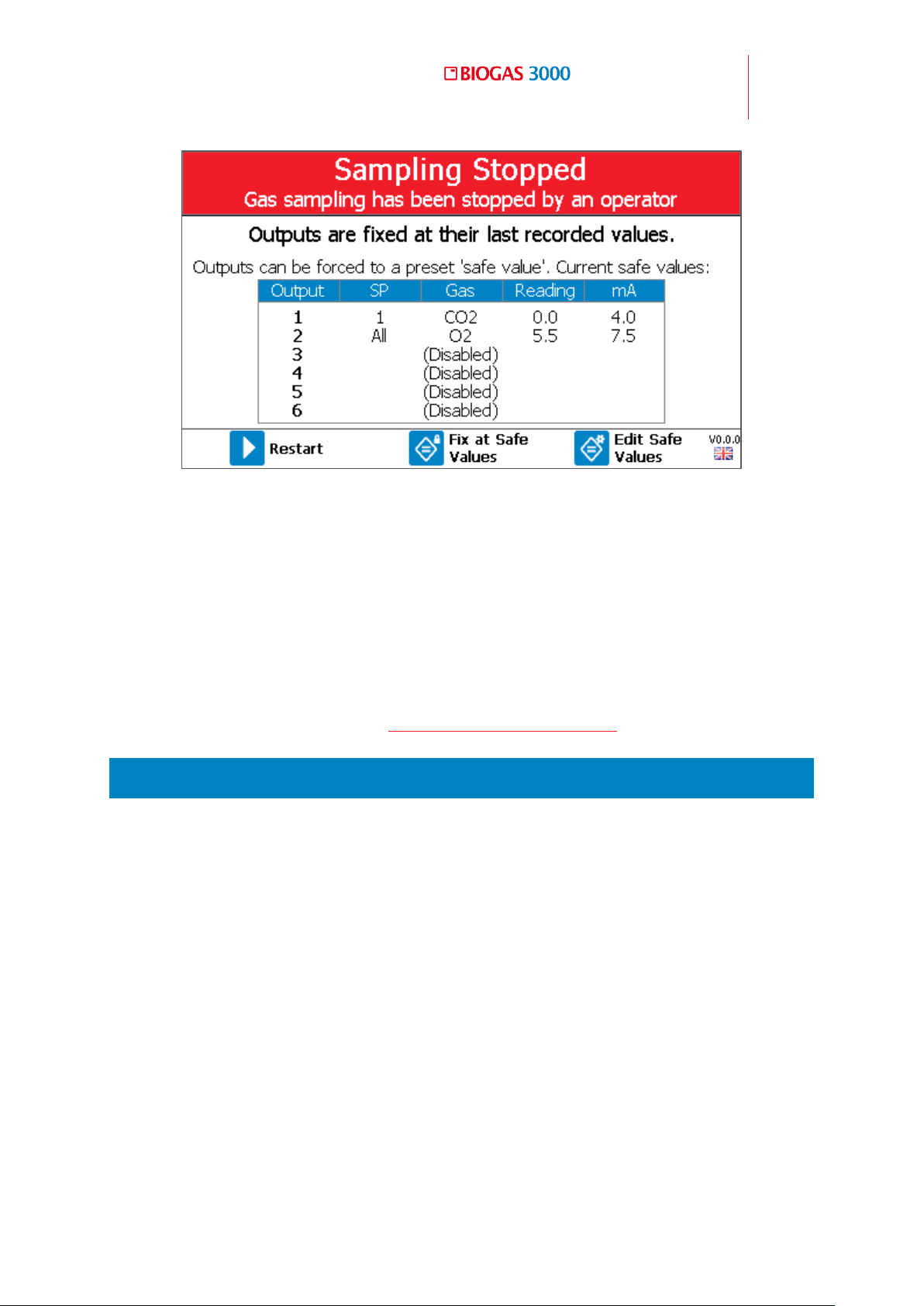
Operating Manual
General Operating Instructions
91
© Copyright 2016
OMBG3000 – Rev1
Screen 8 - Sampling Stopped
Pressing the left soft key will ‘Restart’ the sampling process and return the user
to the ‘Gas Readings Screen’.
Pressing the middle soft key will fix the outputs to the pre-determined safe
values. These are shown in the table onscreen.
Pressing the right soft key allows the user to edit the safe values. For more
information on this, please see Configure Analog Outputs.
5.7 Menu
The menu enables the operator to select options to set-up specific parameters
and perform operational tasks.
The menu is divided in to three areas:
1) Settings – this menu appears from the ‘Gas Readings Screen’ when
pressing the ‘Menu’ key
2) Calibration – this menu is accessed from either the ‘Settings’ menu or the
‘Device Info’ menu by pressing the middle soft key
3) Device Info – the device information menu is accessed from either the
‘Settings’ menu by pressing the left soft key.
Page 92
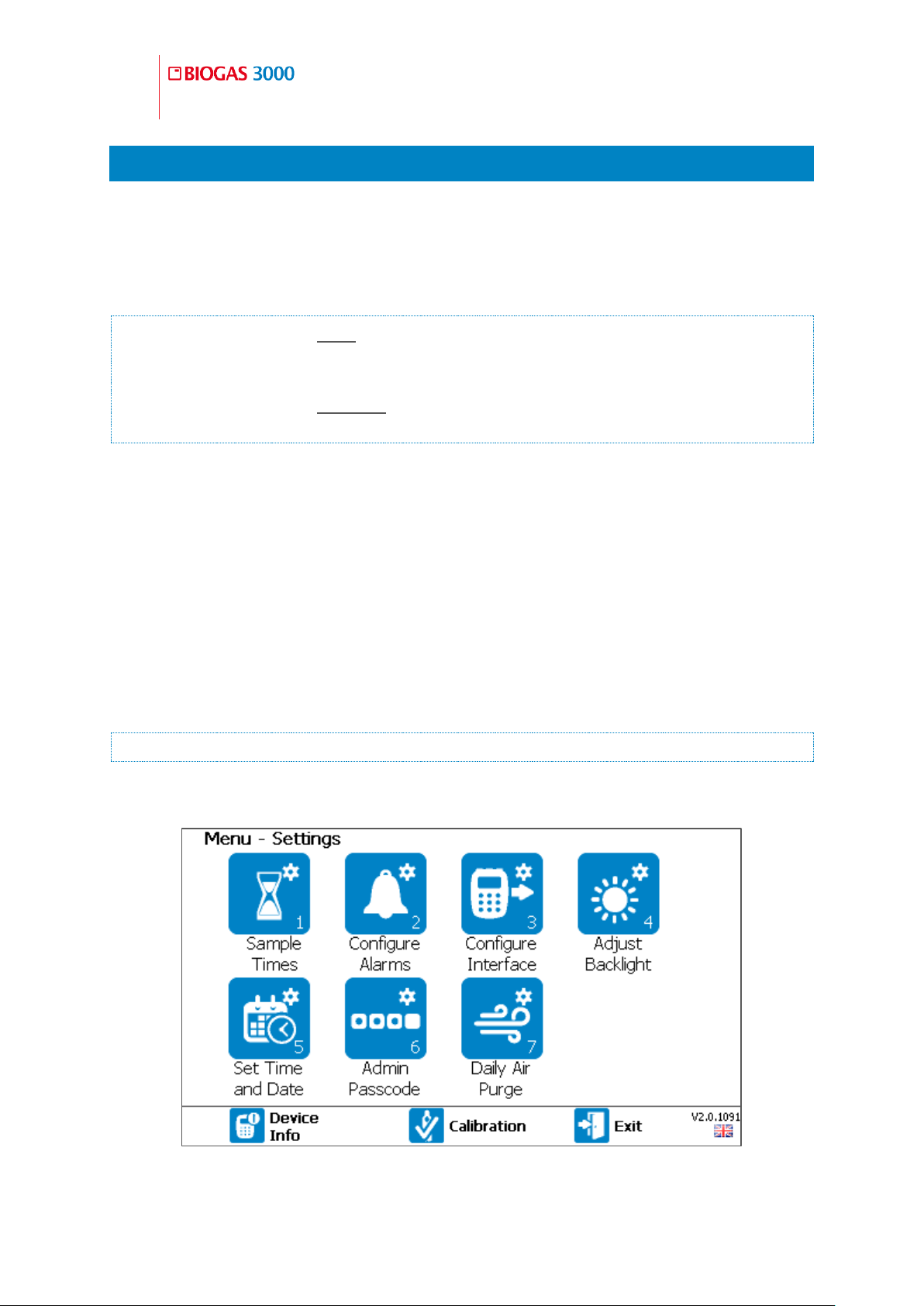
92
Operating Manual
General Operating Instructions
OMBG3000 – Iss.01
© Copyright 2016
Settings Menu 5.7.1
Depending on the option chosen at manufacture, the following options are
available from the settings menu:
1) Sample Times
Note: On a BG3KE with an external cell, this option will be for the
external cell sample options as the rest of the system runs continuously.
Note: On a BG3KE without an external cell, this option will be the daily air
purge.
2) Configure Alarms
3) Configure Interface
4) Adjust Backlight
5) Set Time and Date
6) Admin Passcode
7) Daily Air Purge
Note: This option is only available on BG3KE variants.
An example of the ‘Settings’ menu is shown below.
Screen 9 - Settings Menu
Page 93
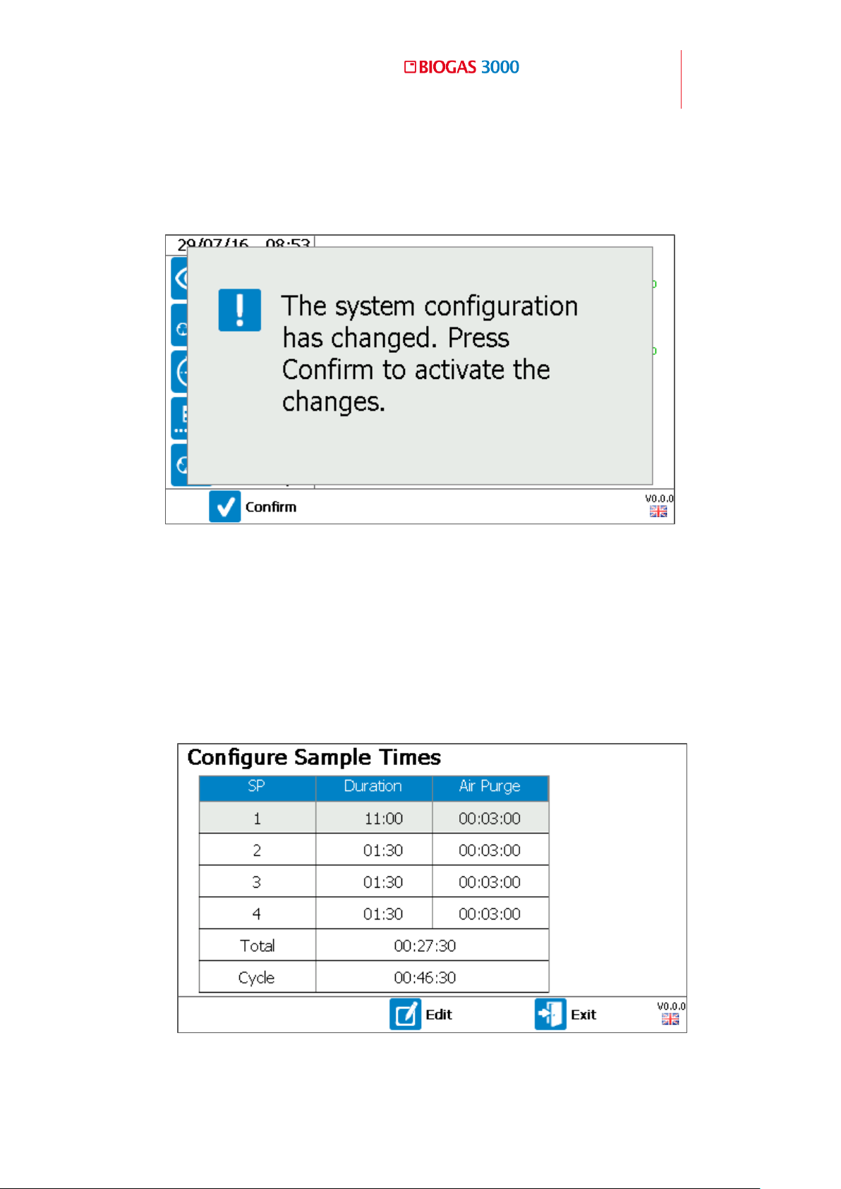
Operating Manual
General Operating Instructions
93
© Copyright 2016
OMBG3000 – Rev1
Following a change to ‘Sample Times’, ‘Configure Interface’, or ‘Daily Air
Purge’, when returning to the ‘Gas Readings Screen’, the system will apply the
new configuration once ‘Confirm’ is pressed using the left soft key.
Screen 10 - Confirm new configuration
5.7.1.1 Sample Times
This option allows the operator to define the duration of each sample point (or
the external sensor if the system is a BG3KE).
1) From the ‘Settings’ menu press key ‘1’ to select the ‘Sample Times’ option.
A summary screen will be shown.
Screen 11 - Configure Sample Times (Non-E variant)
Page 94
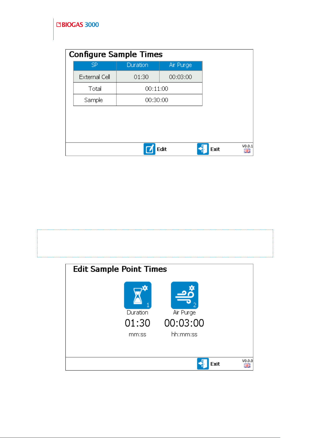
94
Operating Manual
General Operating Instructions
OMBG3000 – Iss.01
© Copyright 2016
Screen 12 - Configure Sample Times (E variant)
2) Press the right soft key to ‘Exit’ without saving any changes.
3) To edit a parameter, press the middle soft key to enter ‘Edit’ mode.
4) Using the scroll keys, select a sample point to edit (highlighted in the
table) and select the field with the key.
Note: In addition to each sample point being editable, the ‘Sample’ time
is also an editable parameter. This is the total time of the cycle before
sample point 1 (or external cell) is monitored again.
Screen 13 - Edit Sample Point Times
Page 95
Operating Manual
General Operating Instructions
95
© Copyright 2016
OMBG3000 – Rev1
5) Press key ‘1’ to edit the sample duration or key ‘2’ to edit the air purge
duration.
6) Key in a suitable time for the system and store using the key.
Note: Both parameters have minimum and maximum values that can be
entered. If a time is outside of this range, the user will be prompted to
enter a more suitable time.
7) Once a parameter has been changed, the left soft key becomes available
to ‘Save and Exit’. Once pressed, the user will be returned to the summary
screen.
Note: If changing a duration exceeds the ‘Sample’ time, the ‘Sample’ time
will automatically be updated to accommodate the change.
8) Press the right soft key to ‘Exit’ back to the ‘Settings’ menu.
5.7.1.2 Configure Alarms
This option allows the operator to define alarm conditions for a gas on any
given sample point.
The relays operate in fail-safe mode. This means the relay is normally
energized. When an alarm condition is met, the relay de-energizes.
Note: The quantity of available alarms will be dependent on the relay
configuration, see Configure Relays section. The relay configuration
should be determined before configuring the alarms.
1) From the ‘Settings’ menu press key ‘2’ to select the ‘Configure Alarms’
option.
Page 96
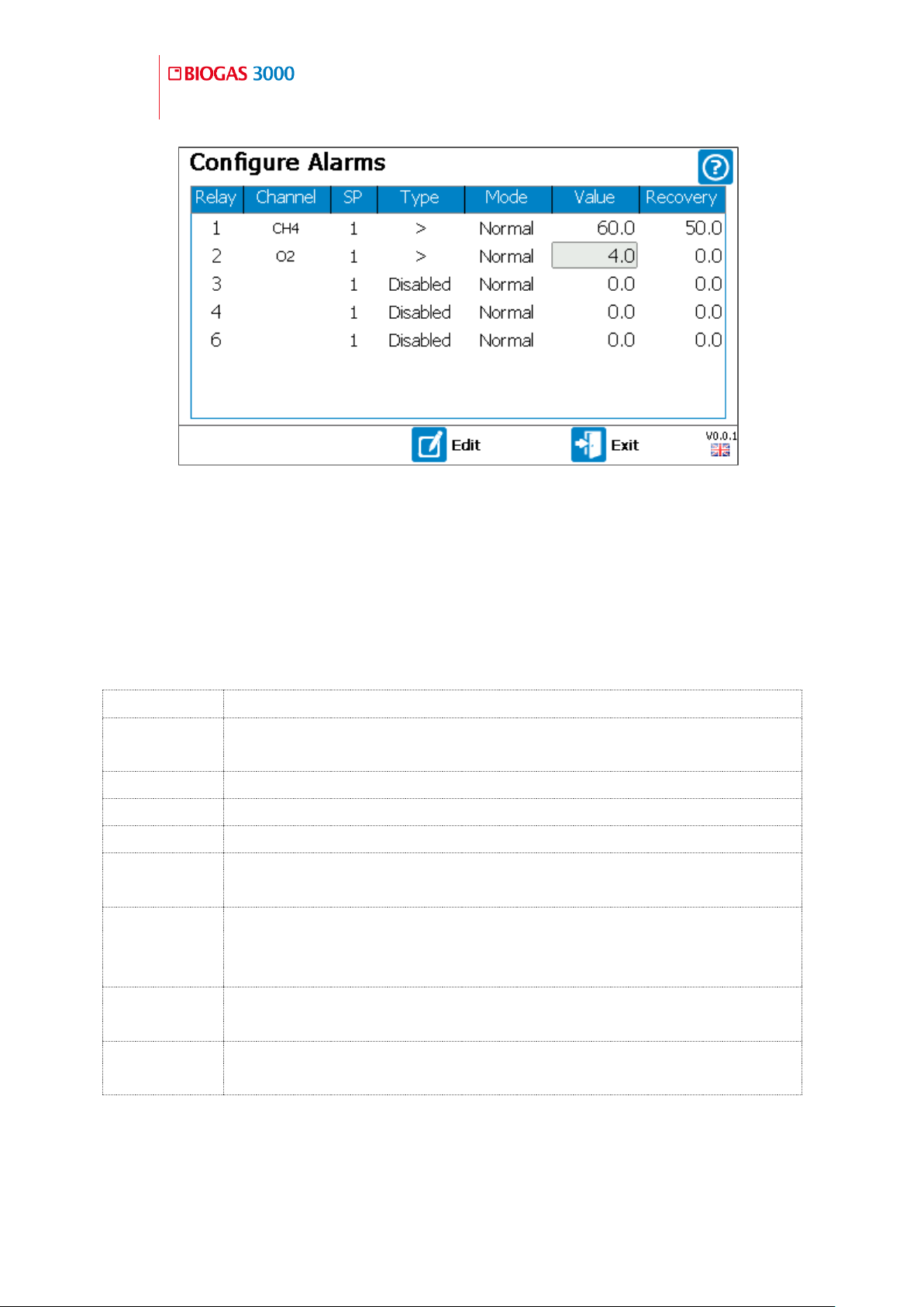
96
Operating Manual
General Operating Instructions
OMBG3000 – Iss.01
© Copyright 2016
Term
Definition
SP
The sample point (1, 2, 3, 4, or All) for which the alarm
condition is to be monitored.
>
Alarm to trigger above the value.
<
Alarm to trigger below the value.
Disabled
Alarm is disabled and will not activate.
Normal
When an alarm has occurred and the gas concentration
reaches its recovery value, the alarm will deactivate.
Latched
When an alarm has occurred and the gas concentration
reaches its recovery value, the alarm will remain activate until
cleared by the operator.
Value
The gas concentration for which the alarm condition will
become active.
Recovery
The gas concentration for which the alarm condition will
recover.
Screen 14 - Configure Alarms
2) Press the right soft key to ‘Exit’ without saving any changes.
3) To ‘Edit’ a parameter, press the middle soft key to enter edit mode. Using
the scroll keys, select a parameter to edit (highlighted in the table) and
select the field with the key.
Definitions
4) Use the scroll keys to select the chosen parameter and select using the
key, or use the keypad to enter the gas concentration for the value
followed by the key to confirm.
Page 97

Operating Manual
General Operating Instructions
97
© Copyright 2016
OMBG3000 – Rev1
5) Once a parameter has been changed, the left soft key becomes available
to ‘Save and Exit’. Once pressed, the user will be returned to the ‘Settings’
menu.
Note: Alarm settings become active immediately.
Note: When any alarm setting is updated all active alarms will reset.
5.7.1.3 Configure Interface
This option allows the operator to configure the various interface options with
the system to the client’s side. There are three options in this sub-menu:
1) Configure Analog Outputs
2) Configure Modbus Slave
3) Configure Relays
To ‘Exit’ this screen press the right soft key to return to the ‘Settings’ menu.
Configure Analog Outputs
This option allows the user to configure the six 4-20mA analog outputs. The
user can define a gas on any given sample point and set the safe-value that is
output should the customer select this option via the Stop Sampling feature.
Note: The safe value is a gas concentration that will force the 4-20mA and
Modbus registers to pre-fixed values. This is to prevent erroneous errors
or alarm conditions in the user’s remote system whilst maintenance is
being performed on the BIOGAS 3000 or any other plant equipment.
1) From the ‘Configure Interface’ menu press key ‘1’ to select the ‘Configure
Analog Outputs’ option.
Page 98
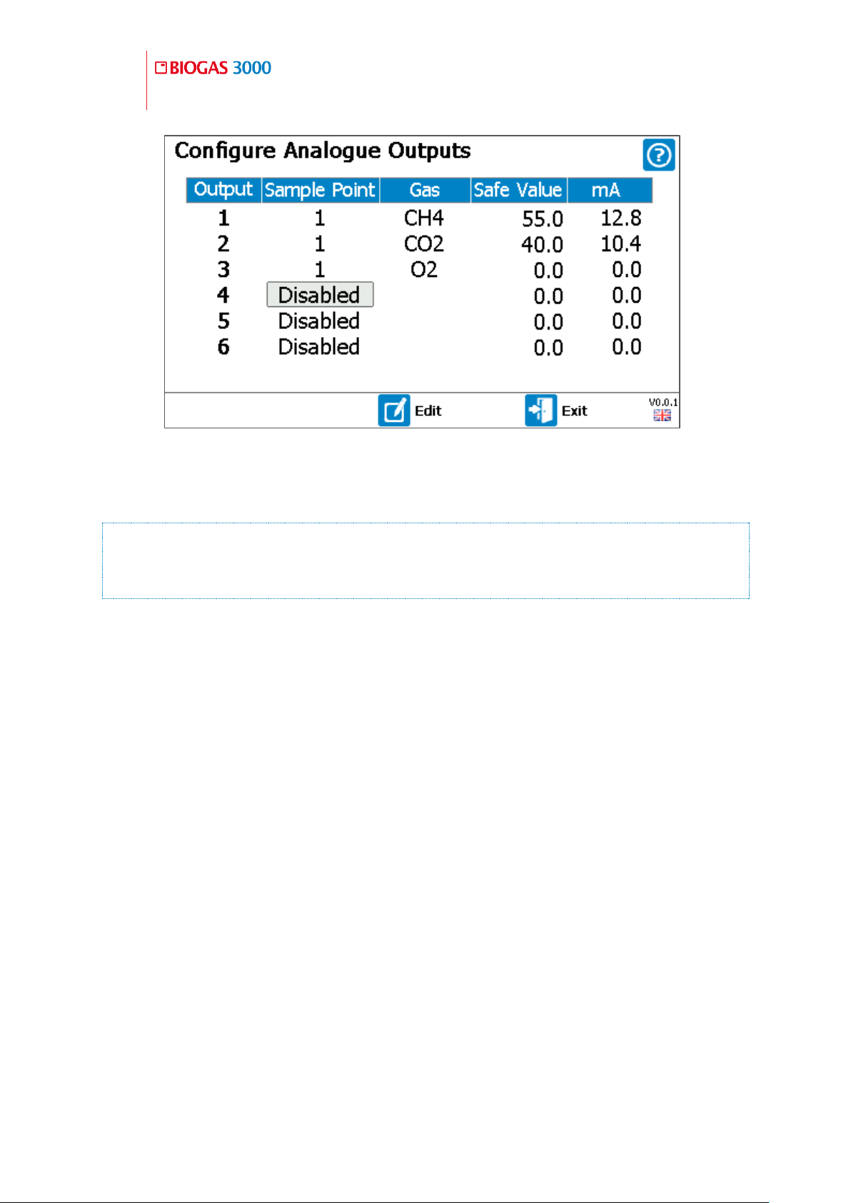
98
Operating Manual
General Operating Instructions
OMBG3000 – Iss.01
© Copyright 2016
Screen 15 - Configure Analogue Outputs
2) Press the right soft key to ‘Exit’ without saving any changes.
Note: If the user has accessed the ‘Configure Analogue Outputs’ screen
via the ‘Stop Sampling’ screen, the user will be returned to the ‘Stop
Sampling’ screen.
3) To ‘Edit’ a parameter, press the middle soft key to enter edit mode. Using
the scroll keys, select a parameter to edit (highlighted in the table) and
select the field with the key.
4) Use the scroll keys to select the chosen parameter and select using the
key, or use the keypad to enter the gas concentration for the safe value
followed by the key to confirm.
5) Once a parameter has been changed, the left soft key becomes available
to ‘Save and Exit’. Once pressed, the user will be returned to the
‘Configure Interface’ menu.
Configure Modbus Slave
This option allows the user to configure the Modbus digital output of the
BIOGAS 3000. The user can change the following parameters:
Slave Address – this is the address of the BIOGAS 3000 on the bus
Baud Rate – Information is transferred in a communication channel at
this rate. Modbus is typically 9600 or 19200
Page 99
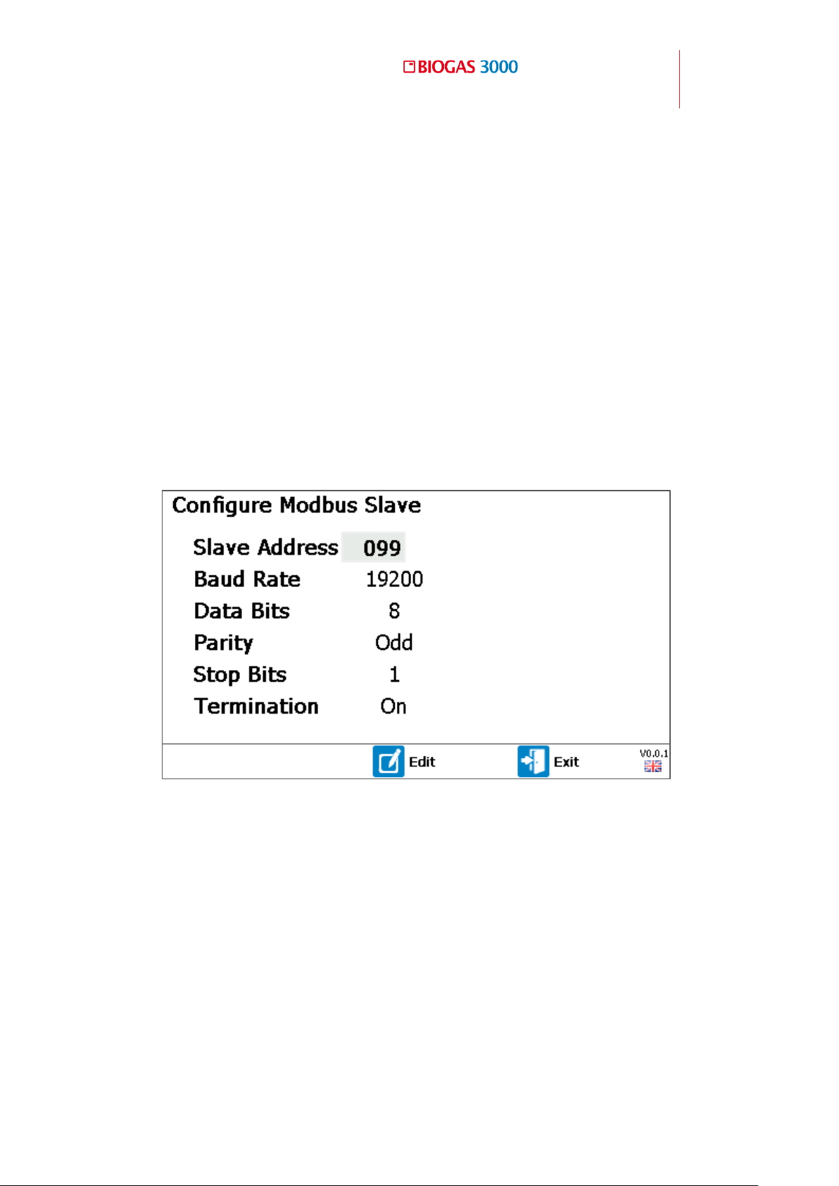
Operating Manual
General Operating Instructions
99
© Copyright 2016
OMBG3000 – Rev1
Data Bits – the number of bits used to represent one character of data.
This parameter cannot be changed
Parity – the parity bit is used as a simple error detection algorithm.
Setting parity to odd will result in an odd number of 1 bits
Stop Bits – this is the number of bits to identify the end of a byte. This is
typically set to 1
Termination – this is used to enable/disable the termination resistor
within the system. This is typically enabled for systems that are the first
or last connection on the bus.
1) From the ‘Configure Interface’ menu press key ‘2’ to select the ‘Configure
Modbus Slave’ option.
2) Press the right soft key to ‘Exit’ without saving any changes.
3) To ‘Edit’ a parameter, press the middle soft key to enter edit mode. Using
4) Use the scroll keys to select the chosen parameter and select using the
Screen 16 - Configure Modbus Slave
the scroll keys, select a parameter to edit (option will be highlighted) and
select the field with the key.
key, or use the keypad to enter the numeric required followed by the
key to confirm.
Page 100
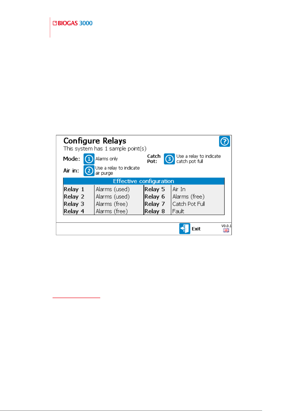
100
Operating Manual
General Operating Instructions
OMBG3000 – Iss.01
© Copyright 2016
5) Once a parameter has been changed, the left soft key becomes available
to ‘Save and Exit’. Once pressed, the user will be returned to the
‘Configure Interface’ menu.
Configure Relays
This option allows the user to configure the eight relays in the system. ‘Relay 8’
is the fault relay and cannot be changed.
1) From the ‘Configure Interface’ menu press key ‘3’ to select the ‘Configure
Relays’ option.
Screen 17 - Configure Relays
2) Press the right soft key to ‘Exit’ without saving any changes.
3) Press key ‘1’ to change the ‘Mode’ of the relays. Available options are:
Alarms only – Relays are only used to indicate an alarm status (refer to
Configure Alarms for information on how to define alarm settings)
Indicate 4-20mA outputs sample point – This mode enables a relay for
when the 4-20mA signal is valid for a given sample point. This is useful if
a 4-20mA output is being used to obtain the gas reading for a single gas
channel across all sample points
 Loading...