

Page 1
The
Audio ToolSet 2
Suite
build 3.0
manual
Page 2

A u d i o T o o l S e t 3 . 0
Nashville, TN, USA
www.landrudesign.com
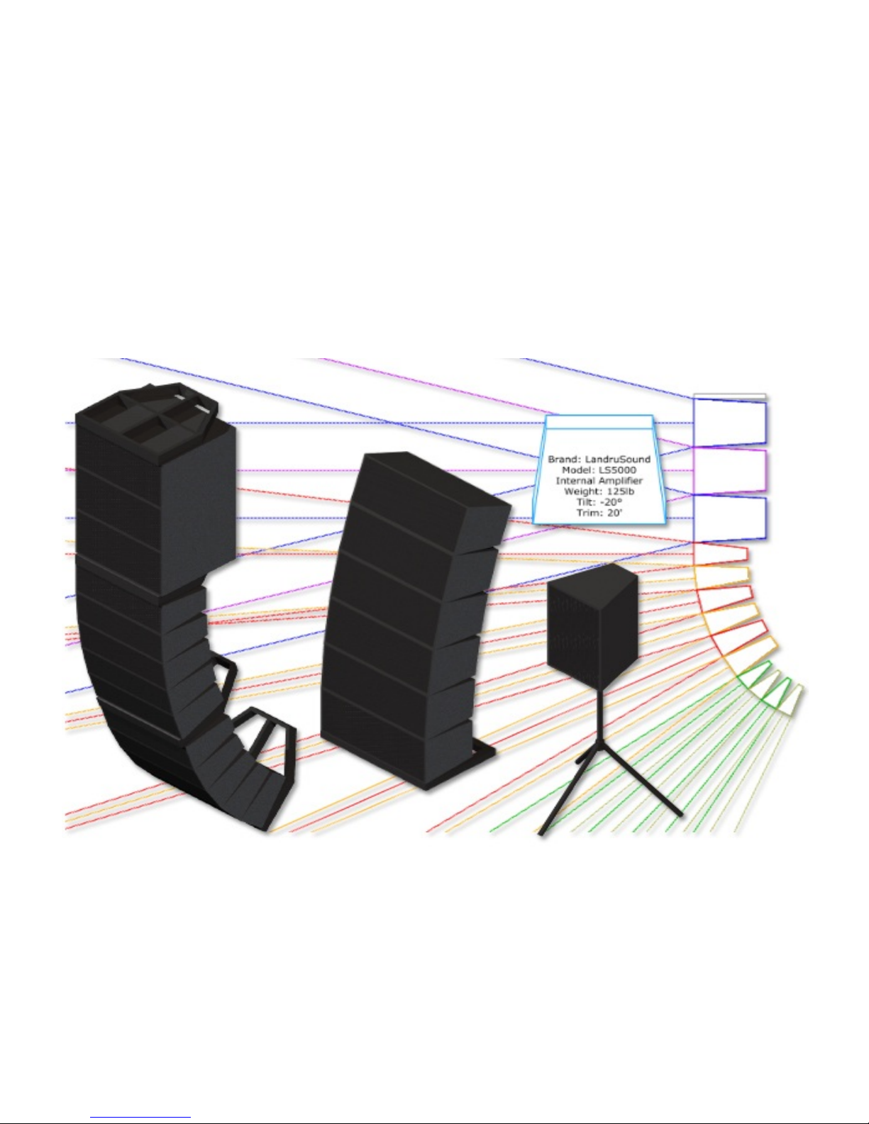
Audio ToolSet 2 is a trio of Vectorworks® Plug-In Objects that enable you to insert simple Hybrid (2D and 3D) models
of loudspeakers and flown line arrays. While they are not meant to replace (or even approach the complexity of)
manufacturers’ or 3 -party high-end sonic analysis software, these flexible tools give Vectorworks® users considerable
power...: to perform basic audio coverage analysis, to create audio system layout drawings, to check general space
requirements, and to visualize audio components for projects.
Notable features of Audio ToolSet 2:
For all three of the tools...
• Because the objects generated are not based on fixed Symbols, loudspeaker and bumper geometry can easily be
changed on-the-fly based on specifications users enter.
• Regularly-used configurations can be saved in a Library for later retrieval. NEW in Audio ToolSet 2.5, loudspeaker
and bumper types have user-assignable names. (For example, a loudspeaker’s Brand and Model might be "Landru
Design" and "LD6000" but a user can store the Type as "Mid/High.") Bumper and loudspeaker specifications are
stored independently of each-other and can now be deleted without users' having to edit the external Library file
manually.
• The tools help to track relevant information, like brands and models, weights, locations, purposes, drive lines, trim
heights, and tilt angles. Most of this information can be displayed directly on drawings as text blocks.
• NEW in Audio ToolSet 2.5, stock loudspeaker and bumper information can be imported from appropriately-
configured Vectorworks® files. These files can also be easily shared with other users.
• NEW in Audio ToolSet 2.56, loudspeakers can be easily turned “side-ways” using the “Flip Orientation” toggle.
• NEW in Audio ToolSet 2.61, the “Weight” fields now recognize kilograms and U.S. pounds. The given units are
stored in the Library alongside the previous “unitless” weights.
rd
• The different parts of each audio object can be assigned to different Classes and, NEW in version 3, users can
choose which parts are assigned to Classes and can define custom Class names.
p a g e 2 o f 1 9
Page 3

A u d i o T o o l S e t 3 . 0
AudioBox 2...
• Allows the display of variable horizontal and vertical dispersion areas (in both 2D and 3D). The dispersion lines
compensate for the project “floor” (the drawing Ground Plane) and a user-defined listening height. NEW in
AudioBox 2, three independently-definable Dispersion Ranges can be defined so users can visualize loudspeaker
performance for different frequency ranges, key frequencies, or crossover points. Each range can be independently
Classed and is color-coded. NEW in version 3, horizontal dispersions can be asymmetrical.
• Will track different support options (flown, stacked, tripod, etc.). NEW in AudioBox 2: While the other "Support"
options remain reference-only, if "Tripod" is chosen, a floor stand will be created with adjustable height. NEW in
AudioBox 3 is the “Yoked” “Support option, which creates a yoke and clamp for the loudspeaker.
• NEW in version 3, ceiling speakers can be created, in addition to the standard “cabinet” loudspeakers possible in
previous versions.
• NEW in version 3, speaker wattages (Minimum, RMS, and Peak) can be tracked.
AudioArray 2...
• Will insert up to 42 loudpeakers and/or additional bumpers in a given array and, NEW in AudioArray 2, of up to
three different AudioBox 2 types in each - for things like subs, underhangs, etc. Geometry and data for each
loudspeaker type is totally independent of the others.
• NEW in AudioArray 2, element-to-element angles are independent for each loudspeaker in the array.
• Uses a NEW AudioArray 2 user-friendly “"Array Detail and Configuration” dialog. This dialog includes
automatically-updated preview windows so users can instantly see what they’re creating - bumpers, loudspeakers -
and/or changes to the over-all array.
• NEW in version 2.5, loudspeakers can be inserted for multiple arrays at the same time.
• NEW in version 2.55, arrays can be ground-stacked in addition to being flown.
• NEW in version 2.55, trapezoidal or chamfered bumpers can be created.
• NEW in version 2.55, bumperless arrays can be created.
• NEW in version 2.56, tripod-mounted arrays can be created.
• NEW in version 2.55, speakers can be shifted backward and forward relative to their bumpers.
• NEW in version 2.61, the “Update” button now fixes misarranged arrays.
• NEW in version 2.61, AudioBumper 2 has been added, allowing multiple bumpers (pull-back and transitional) to be
inserted.
• NEW in version 2.61, extension bars can now be created and stored with defined bumpers in the Library.
p a g e 3 o f 1 9
Page 4

A u d i o T o o l S e t 3 . 0
• NEW in version 2.61, rigging guides can now be shown, marking potential insertion points for hoist Symbols and
Plug-In Objects.
• NEW in version 3, speaker Rack and Drive Line data can be entered in the “Array Detail and Configuration” dialog.
p a g e 4 o f 1 9
Page 5

A u d i o T o o l S e t 3 . 0
Table of Contents
System Requirements and License . . . . . . . . . . 6
Installation . . . . . . . . . . 7
General Introduction . . . . . . . . . . 8
AudioBox 2 . . . . . . . . . . 9-10
AudioArray 2 . . . . . . . . . . 11-15
AudioBumper 2 . . . . . . . . . . 16
Text Options . . . . . . . . . . 17
Parts Classes . . . . . . . . . . 17
Library File Notes . . . . . . . . . . 18-19
p a g e 5 o f 1 9
Page 6

A u d i o T o o l S e t 3 . 0
Starting with version 3, Audio ToolSet 2 requires
Vectorworks® and Renderworks® 2014 or newer.
License
By downloading and using this (or any) version of any of Audio ToolSet 2, you agree to the following:
1) You agree that you are using Audio ToolSet 2 under a license granted by Landru Design.
2) You agree that all title, ownership, rights, intellectual property rights in and to Audio ToolSet 2 and all copies
thereof, regardless of form (including, but not limited to, computer or source code and any related
documentation), are owned or expressly licensed by Landru Design. Such rights extend to all updates of
Audio ToolSet 2 and any related derivative works.
3) You agree not sell, rent, lend, loan, lease or otherwise transfer or distribute the Audio ToolSet 2 software.
Furthermore, you agree not to modify, dissemble, decompile, or reverse-engineer the Audio ToolSet 2
software.
4) You agree that a download/license of Audio ToolSet 2 is intended for a single, individual user. Please contact
Landru Design for multi-user/site licensing.
5) You agree that this license may be terminated by Landru Design if you fail to comply with its terms and
conditions. You agree that, upon such termination, you will destroy (or permanently erase) all copies of
Audio ToolSet 2.
6) You agree that Audio ToolSet 2 is provided "as is" and is provided without warranty of any kind, either
express, implied, or statutory, including but not limited to, any implied warranties of merchantability or
fitness for a particular purpose. You agree not to hold Landru Design or any of its owners, personnel,
subsidiaries, or affiliates responsible for any damages of any kind resulting from the use of this software,
including but not limited to, inaccuracies, loss of data, loss of goodwill, work stoppage, computer or software
failure or malfunction - and all other direct, indirect, incidental, special, exemplary or consequential damage
and losses. In the event that Landru Design is found liable to you, you agree that such liability shall not
exceed the amount of fees paid by you for the use of Audio ToolSet 2.
7) You understand and agree that the calculations and any suggested weights provided by these tools are
intended as estimates only and that Landru Design makes absolutely no representations, guarantees, or
warranties regarding their accuracy. You acknowledge that you are STRONGLY advised to perform your
own calculations and to confirm all weights. You agree to assume all liability arising from using these tools
and agree to hold harmless and indemnify Landru Design in the event that miscalculations and/or inaccurate
data cause or allow loss or damage of any kind.
p a g e 6 o f 1 9
Page 7

A u d i o T o o l S e t 3 . 0
Installation
Audio ToolSet 2 consists of four files:
• AudioBox 2.vso
• AudioArray 2.vso
• AudioBumper 2.vso
• LandruStrings.vwr (or, for Vectorworks 2014®, LandruStrings.xml)
Copy all four files to the Plug-Ins folder of your Vectorworks® folder (or, your User folder).
Vectorworks® should not be running during the file copying process.
Next, start Vectorworks® and add the tools to your favorite Workspace. If you've never done that before
and are not near your Vectorworks® manual:
1) Click...[Tools]...[Workspaces]...[Workspace Editor]. Make sure "Edit current workspace" is
selected and click "OK."
2) In the resulting dialog, click the "Tools" tab.
3) Scroll down the available tool section (the left side) until you see the "Landru" section. Click the
"+."
4) Drag the AudioBox 2 and AudioArray 2 icons to an existing palette or create a new palette (or
Tool Set) and drag the icons there. (Do NOT add AudioBumper 2 to your Workspace.)
5) Click "OK."
p a g e 7 o f 1 9
Page 8

A u d i o T o o l S e t 3 . 0
Using Audio ToolSet 2
Choose the Audio ToolSet 2 icon for the particular tool you wish to use (AudioBox 2 or Audio Array 2) from
the Tool Set to which you added it earlier. A ghost image of the object’s default geometry will appear in
your drawing window. Click in your drawing to place the AudioBox 2 or Audio Array 2 object. Rotate the
object to the desired angle and click again (like placing Vectorworks® symbols).
With the newly-placed object selected, use the Object Info Palette to make adjustments. If the Shape tab is
not in the forefront of the Object Info Palette, click it to make it so.
AudioBox 2’s tools’ different parameter settings are detailed in the next 2 pages. AudioArray 2 has
additional steps in its use. See pages 11-16 for more information.
If you are transitioning to this version - either from a build older than 2.61 or from the audio tools included
with Vectorworks Spotlight® - expect the tools to ask you from time-to-time what weight units (lb or kg)
were intended when working with Plug-In Object instances or Library items created with those versions.
See pages 18-19 for more information.
Please forgive any discrepancies between this manual, its illustrations, and reality. It is often easier
to make software fixes and/or additions than it is to keep a manual current.
p a g e 8 o f 1 9
Page 9
A u d i o T o o l S e t 3 . 0
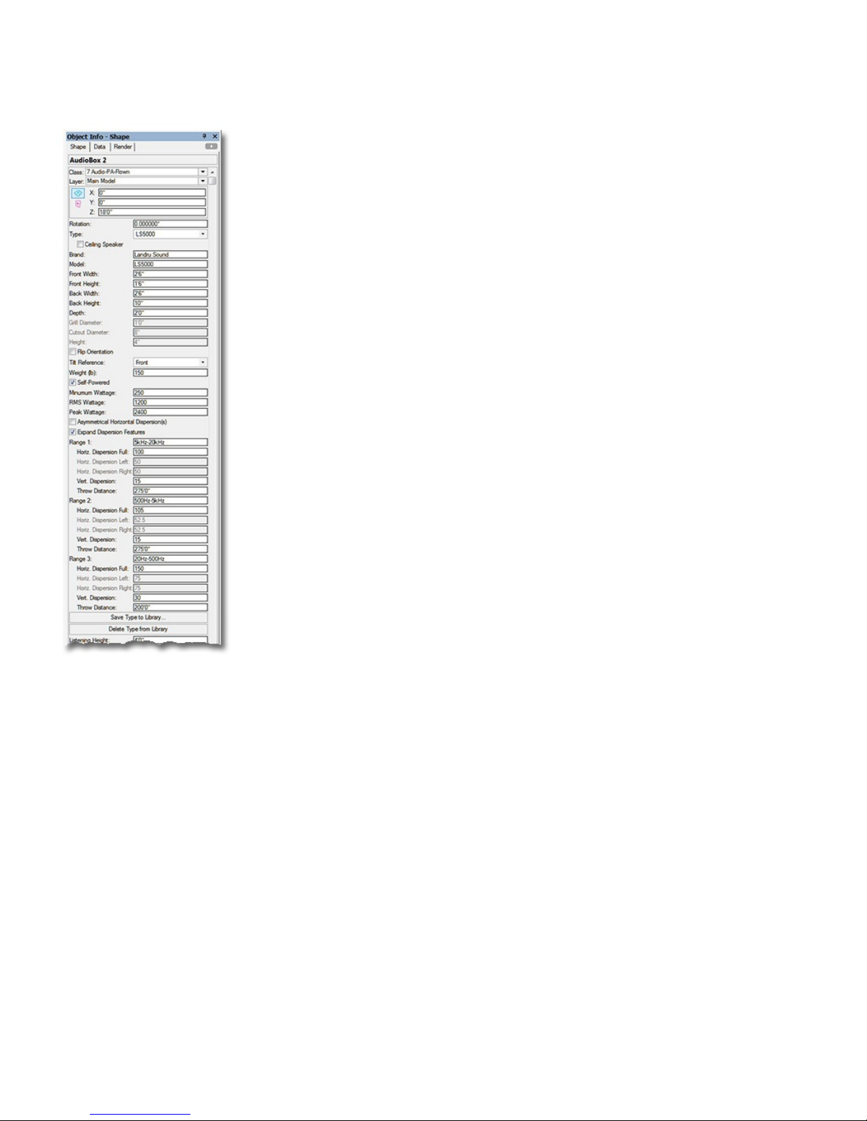
AudioBox 2 parameters
Class, Layer, X, Y, Z, and Rotation: Settings similar to other Vectorworks® symbols and objects. (“Z” is the distance
from the drawing’s ground plane to the bottom front center of the loudspeaker or to the bottom of the floor stand if
“Tripod” is chosen under “Support”).
Type: A list of predefined loudspeakers. The only option is “<Generic>” unless you have saved custom loudspeaker types
to the Library using the Save to Library button (see below). If so, your additions will be listed here, as-well.
Selecting a stored type will populate many of the parameters below. Choosing the “Import...” option will cause the
“Import Speaker Type” dialog to open, which will allow loudspeaker data to be imported from appropriately-
configured Symbols in Vectorworks® files found in the “...Libraries/Defaults/Audio Tools/Speakers” folder.
Ceiling Speaker: Causes ceiling speakers to be created, as opposed to in addition to the standard "cabinet” type.
Brand and Model: Places for entering the loudspeaker brand and model.
Front Width and Front Height: The width and height of the front face of the loudspeaker. (Only available if “Ceiling
Speaker” is NOT selected.)
Back Width and Back Height: The width and height of the back face of the loudspeaker. (Only available if “Ceiling
Speaker” is NOT selected. Back Width and Back Height cannot be larger dimensions than the Front Width and
Front Height.)
Depth: The depth of the loudspeaker. (Only available if “Ceiling Speaker” is NOT selected.)
Grill Diameter: The diameter of a ceiling speaker’s front grill. (Only available if “Ceiling Speaker” is selected.)
Cutout Diameter: A ceiling speakers cutout or “can” diameter. (Only available if “Ceiling Speaker” is selected.)
Height: A ceiling speaker’s height (or, depth). (Only available if “Ceiling Speaker” is selected.)
Flip Orientation: Flips the loudspeaker to a “side-ways” orientation. (Only available if “Ceiling Speaker” is NOT
selected.)
Tilt Reference: The reference that AudioArray 2 uses when setting the tilts of each box in an array - either the front or back
face of the loudspeaker. (Only available if “Ceiling Speaker” is NOT selected.)
Weight (lb) or Weight (kg): The loudspeaker’s weight. If the drawing units are Imperial, this should be entered in U.S.
pounds. If the drawing units are Metric, this should be entered in kilograms. When the weight is entered in a given
unit, the other is automatically calculated and stored.
Self-Powered: A toggle for noting whether the loudspeaker uses an internal or remote amplifier.
Minimum Wattage, RMS Wattage, and Peak Wattage: Places for entering wattage data.
Asymmetrical Horizontal Dispersion(s): A toggle to enable asymmetrical horizontal dispersions.
Expand Dispersion Features: A toggle for enabling Range notes and Dispersion area information beyond a simple
“Overall”.
Range 1, Range 2, and Range 3: Places for entering notes for the three Dispersion Ranges (for example, a frequency range,
key frequency, or crossover point). (These parameters are only enabled if Expand Dispersion Features is toggled
on.)
Horiz. Dispersion Full, Horiz. Dispersion Left, Horiz. Dispersion Right: Horizontal dispersion angles. “Full” is the
sum of “Left” and “Right.” “Left” and “Right” are relative to a loudspeaker facing “down-screen.” (The “full”
angles can be between 0° and 180°. The Dispersion parameters for Range 2 and Range 3 are only enabled if
Expand Dispersion Features is toggled on.)
Vert. Dispersion: Horizontal and vertical dispersion angles. (These angles can be between 0° and 180°. The Dispersion
parameters for Range 2 and Range 3 are only enabled if Expand Dispersion Features is toggled on.)
Throw Distance: The throw distance reference for the dispersion lines. (The Throw Distances for Range 2 and Range 3
are only enabled if Expand Dispersion Features is toggled on.)
Save to Library (button): Saves key loudspeaker information to an external data file for later use. (See Type, above.)
When this button is clicked, a dialog opens, allowing the assignment of a custom Type name. Though the default
name is [Brand]-[Model], a new name can be entered. (For example, the Brand and Model in this OIP are “Landru
Sound” and “LS5000" but the Type could be“Fill,” “Full-Range,” “Sub,” etc. - “LS5000" used in the example OIP.)
This Type name is what appears in the Type pop-up. (See pages 18-19 for more information on the Audio ToolSet 2
Library system.)
Delete From Library (button): Deletes a selected loudspeaker Type from the external data file. (Only enabled if a non-
Generic Type from the Library is selected. See Type, above.)
p a g e 9 o f 1 9
Page 10
A u d i o T o o l S e t 3 . 0
AudioBox 2 parameters, continued...
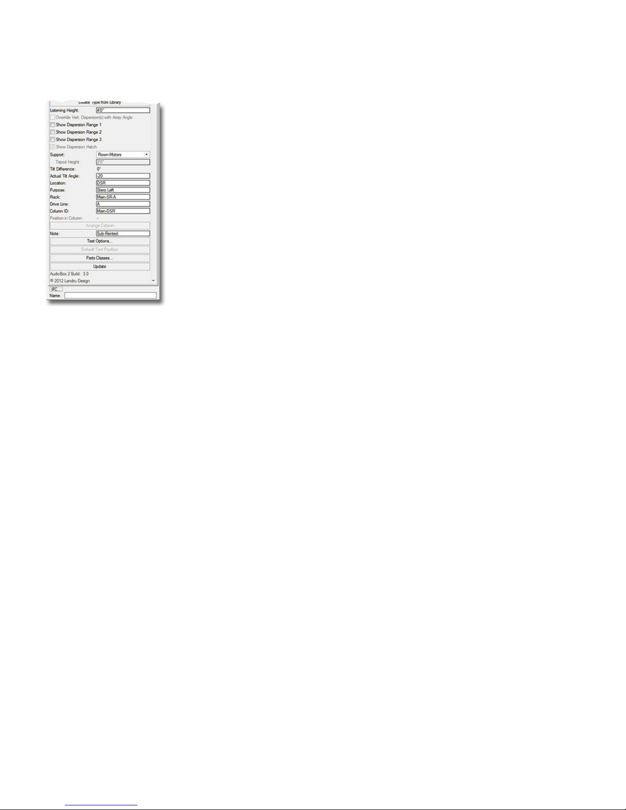
Listening Height: The listening height reference for the dispersion lines. (Listening Height cannot be higher than a given
AudioBox 2 model’s “Z” value.)
Override Vert. Dispersion(s) with Array Angles: Will use Angle Relative... angle instead of stated Vertical Dispersion
angles when drawing Dispersion lines. (See Tilt Difference below and Angle Relative... on page15 for more
information. Only enabled if the AudioBox 2 instance has been placed by AudioArray 2.)
Show Dispersion Range 1, Show Dispersion Range 1, and Show Dispersion Range 1 : Draws top, bottom, left, and
right dispersion lines, and a center reference for each of the three Dispersion ranges. Also, an outline and hatch
representing the listening area coverage “shadow” will be drawn if the Vertical Dispersion angle, Throw Distance,
and Tilt Angle allow the loudspeaker to cover the Listening Height or below. (The toggles for Range 2 and Range 3
are only enabled if Expand Dispersion Features is toggled on.)
Show Dispersion Hatch: Adds a hatch pattern to represent the listening area coverage “shadow” if the Vertical Dispersion
angle, Throw Distance, and Tilt Angle of any of the enabled ranges allow the loudspeaker to cover the Listening
Height or below, in addition to the “shadow’s” outline. (Only enabled if one of the Dispersion Ranges is shown.
See Show Dispersion Range 1, Show Dispersion Range 2, and Show Dispersion Range 3, above.)
Support: A pop-up menu of support options. While the other options are reference-only, if “Tripod” is selected, AudioBox
2 will create a tripod floor stand. (Only available if “Ceiling Speaker” is NOT selected.)
Stand Height: The height of the floor stand. (Only enabled if “Ceiling Speaker” is NOT selected and only if the “Tripod”
“Support” is selected.)
Tilt Difference: The tilt difference between the selected loudspeaker and the bumper or loudspeaker above it, once the
Arrange Column button has been clicked - or as determined by the AudioBox 2 object’s being placed by AudioArray
2. (Only available if “Ceiling Speaker” is NOT selected.)
Actual Tilt Angle: The actual tilt of the loudspeaker. (Only available if “Ceiling Speaker” is NOT selected. Negative
numbers tilt the cabinet down; positive, up. AudioBox 2 will not allow the loudspeaker to tilt more than 90° or less
than -90°.)
Location: A place for entering the loudspeaker location (such as Downstage Right).
Purpose: A place for entering the loudspeaker purpose (such as Center Fill).
Rack: A place for entering information about the rack driving the loudspeaker.
Drive Line: A place for entering information about the drive line feeding signal to the loudspeaker.
Column ID: The name for the column (if any) in which the AudioBox 2 object is placed. This is also the name for the
AudioArray 2 “parent”/“master’ bumper and the “child”/“slave” loudspeaker. This is how the Plug-In Object knows
which loudspeaker or additional models to control - either via the Arrange Column button (see below) or the
AudioArray 2 PIO. (Only available if “Ceiling Speaker” is NOT selected.)
Position in Column: The loudspeaker’s position in its column, once the Arrange Column button has been clicked or the
AudioBox 2 object has been placed or updated by an AudioArray 2 object.. (Only available if “Ceiling Speaker” is
NOT selected. “1" is the top loudspeaker.)
Arrange Column (button): If multiple AudioBox 2 objects are selected, each with different “Z” values - but with matching
Column IDs, clicking this button will adjust the stacking order so that 2D “overlaps” are correct, calculate Tilt
Differences, and assign Position in Column numbers. (Only available if “Ceiling Speaker” is NOT selected.)
Note: A place for entering miscellaneous notes, such as rental source or stock number.
Text Options...: A button to open the “Text Options” dialog, in which text elements are shown, hidden, and/or modified.
(See page 17 for more information).
Default Text Position: A button to return text to its default location. (Only enabled if text has been inserted.)
Parts Classes...: A button to open the “Parts Classes” dialog, used to assign the different elements comprising the
AudioBox 2 model to different Classes.. (See page 17 for more information.)
Update (button): Click this button to regenerate the AudioBox 2 object. You might need to click this if you’re making
changes regarding using Class Attribute settings.
AudioBox 2 Build: The build number of the AudioBox 2 Plug-In Object code.
p a g e 1 0 o f 1 9
Page 11

A u d i o T o o l S e t 3 . 0
AudioArray 2 (introduction)
AudioArray 2 works a little differently than AudioBox 2. Whereas AudioBox 2 inserts a single
loudspeaker cabinet in a single step, AudioArray 2 is actually used to insert a bumper and a
vertical array of loudspeakers and/or additional bumpers in separate steps.
If you’re transitioning from a previous version of Audio ToolSet, note that, as described below, the
approach for using this new version is a little different...
To use AudioArray 2:
1) Click the AudioArray 2 icon in the tool palette to which you added it earlier. A ghost image
of the tool’s default bumper will appear in your drawing. Click in your drawing to place the
bumper. Rotate the bumper to the desired angle and click again to set the angle (like placing
Vectorworks® symbols). If an initial settings dialog box appears, make adjustments and click
“OK” in that box.
2) With the AudioArray 2 object selected, use the Object Info Palette to make basic adjustments
(such as bumper trim height) and to enter general array data. On Audio Array 2' s Object Info
Palette, click the “Configure Array...” button to bring up the “Array Detail and
Configuration” dialog, allowing you to specify array details, loudspeaker counts, or to make
adjustments (such as bumper and loudspeaker dimensions, loudspeaker counts, and hanging
angles). Double-clicking the Audio Array 2 object will also bring up the dialog.
3) Click the "Populate Array" button toward the bottom of the AudioArray 2 Object Info Palette.
AudioArray 2 will place independent “child”/“slave” AudioBox 2 loudspeakers and/or
AudioBumper 2 bumpers that are "connected" to the “parent”/“master” bumper. The
AudioBox 2 and AudioBumper 2 instances are built using dimensions designated in the
AudioArray 2 “Array Detail and Configuration” dialog - and display their own info in the
Object Info Palette. All of the additional bumpers’ settings and the majority of the
loudspeakers’ settings are “fed” by the AudioArray 2 “parent”/“master” object. Once
loudspeakers and/or additional bumpers have been inserted by a given AudioArray 2 object,
changes made in its “Array Detail and Configuration” dialog will automatically rebuild the
array.
AudioArray 2’s parameter settings are detailed on the next pages...
p a g e 1 1 o f 1 9
Page 12
A u d i o T o o l S e t 3 . 0
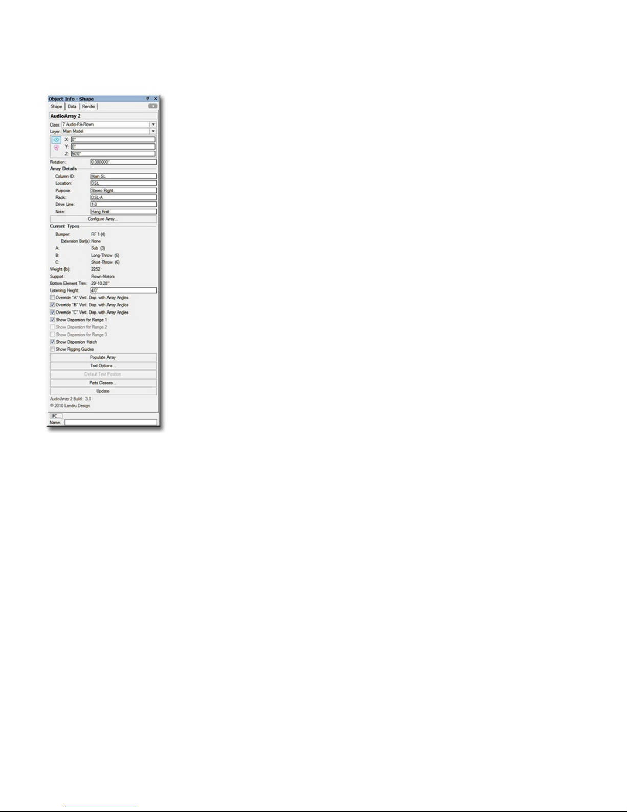
AudioArray 2 parameters
Class, Layer, X, Y, Z, and Rotation: Settings similar to other Vectorworks® symbols and objects. (“Z” is the distance
from the drawing’s ground plane to the bottom front center of the bumper.)
Array Details:
Column ID: The name for the inserted “parent”/“master” bumper and the “child”/“slave” loudspeakers and/or additional
bumpers. Because this is how the Plug-In Object knows which AudioBox 2 and AudioBumper 2 models to control,
each Column ID MUST be unique.
Location: A place for entering the array location (such as DSL).
Purpose: A place for entering the array purpose (such as Stereo Right).
Rack: A place for entering information about the rack driving the loudspeakers.
Drive Line: A place for entering information about the drive line feeding signal to the loudspeakers.
Note: A place for entering miscellaneous notes, such as rental source or stock number.
Configure Array... (button): Opens the “Array Detail and Configuration” dialog. This dialog is where you specify
bumper/support and loudspeaker details and configure the array (tilt angles, loudspeaker and/or bumper counts, and
loudspeaker and/or bumper positions in the array). (See pages 13-15 for more information.)
Current Types:
Bumper: The bumper type defined in the “Array Detail and Configuration” dialog, along with the quantity.
Extension Bar(s): The layout (center or sides) of Extension Bars (if defined).
A, B, or C: The types and quantities of the loudspeakers defined in the “Array Detail and Configuration” dialog.
Weight (lb) or Weight (kg) : After the Populate Array button has been clicked, the estimated total loudspeaker and
bumper weight of the array. If the drawing units are Imperial, this will be shown in U.S. pounds. If the drawing units
are Metric, this will be shown in kilograms. (Remember, THIS IS AN ESTIMATE ONLY. YOU ARE STRONGLY
ADVISED TO CONFIRM ALL CALCULATIONS.)
Support: How the array is supported, as defined in the “Array Detail and Configuration” dialog.
Bottom Element Trim: After the Populate Array button has been clicked, the trim of the bottom loudspeaker or bumper.
Listening Height: The listening height reference for the loudspeakers’ dispersion lines.
Override “A” Vert. Disp. with Array Angles, Override “B” Vert. Disp. with Array Angles , and Override “C” Vert.
Disp. with Array Angles: Will force inserted AudioBox 2 objects to use Angle Relative... angles for each of the three
loudspeaker types instead of stated Vertical Dispersion angles when drawing Dispersion lines. (Only potential
dispersions for loudspeaker definitions actually in the array will be enabled. See Tilt Difference on page 10 and
Angle Relative to Preceding on page 15 for more information.)
Show Dispersion Range 1, Show Dispersion Range 1, and Show Dispersion Range 1 : Causes the AudioBox 2 models
do draw top, bottom, left, and right dispersion lines, and a center reference for each of the three Dispersion ranges for
each of the AudioBox 2 models in the array. (Only ranges allowed by loudspeaker definitions actually in the array
will be enabled. See the AudioBox 2 section in preceding pages and the “Array Detail and Configuration” dialog
section on pages 13-15 for more information.)
Show Dispersion Hatch: Adds a hatch pattern to represent the listening area coverage “shadows” for each of the AudioBox
2 models in the array. (See the AudioBox 2 section in preceding pages for more information.)
Show Rigging Guides: Toggle to mark potential insertion points for hoist Symbols and Plug-In Objects.
Populate Array (button): Inserts AudioBox 2 and/or AudioBumper 2 models or replaces array models if you’ve made
adjustments in the “Array Detail and Configuration” dialog. (Only enabled if at least one loudspeaker or additional
bumper has been added in the “Array Detail and Configuration” dialog. See the “Array Detail and Configuration”
dialog section on pages 13-15 for more information.)
Text Options...: A button to open the “Text Options” dialog, in which text elements are shown, hidden, and/or modified.
(See page 17 for more information.)
Default Text Position (button): Returns text to its default location. . (Only enabled if text has been inserted.)
Parts Classes...: A button to open the “Parts Classes” dialog, used to assign the different elements comprising the
AudioArray 2 model to different Classes.. (See page 17 for more information.)
Update (button): Click this button to regenerate the AudioArray 2 object. You might need to click this if you’re making
changes regarding using Class Attribute settings. This button will also cause the array to be rebuilt or “repaired” using
current settings.
AudioArray 2 Build: The build number of the AudioArray 2 Plug-In Object code.
p a g e 1 2 o f 1 9
Page 13
A u d i o T o o l S e t 3 . 0
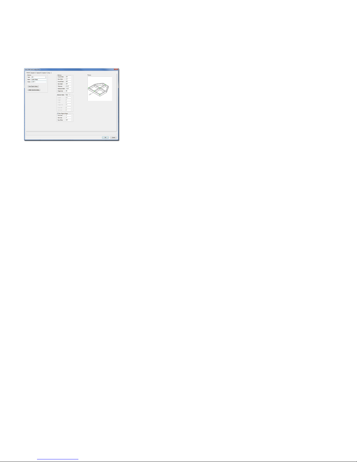
Array Detail and Configuration dialog
Each of the first four tabs (Bumper, Speaker A, Speaker B, and Speaker C) in this dialog is used to define elements that are used in the fifth tab (Array) to create
the array.
Bumper:
Type: A list of predefined bumpers. The only option is “<Generic>” unless you have saved custom
bumper types to the Library using the Save to Library button. If so, your additions will be listed here,
as-well. Selecting a stored type will populate many of the parameters to the right. Choosing the
“Import...” option will cause the “Import Bumper Type” dialog to open, which will allow bumper data to
be imported from appropriately-configured Symbols in Vectorworks® files found in the
“...Libraries/Defaults/Audio Tools/Bumpers” folder. Choosing the “None” option will replace bumper
geometry with Locus points
Brand and Model: Places for entering the bumper brand and model.
Save to Library (button): Saves key bumper information to an external data file for later use. (See Type,
above.) When this button is clicked, a dialog opens, allowing the assignment of a custom Type name.
Though the default name is [Brand]-[Model], a new name can be entered. (For example, the Brand and
Model in this dialog tab are “Landru Design” and “LD-RF 1" but the Type is “RF-1.”) This Type
name is what appears in the Type pop-up. (See pages 18-19 for more information on the Audio ToolSet
2 Library system.)
Delete From Library (button): Deletes a selected bumper Type from the external data file. (Only enabled
if a non-Generic Type from the Library is selected. See Type, above.)
Total Width, Total Depth, and Thickness: The overall width, depth, and thickness of the bumper.
Rear Width: The width of the rear face the bumper.
Side Depth: The measurement of the side face of the bumper, as measured from the front face.
If “Rear Width” and “Side Depth” are less than “Total Width” and “Total Depth” but “Side Depth” is
greater than 0, a “chamfered” bumper will be created. If “Rear Width” is less than “Total Width” and
“Side Depth” is 0, a trapezoidal bumper will be created. Otherwise, a rectangular bumper will be
created.
Hardware Width: The width of the hardware members comprising the bumper.
Any changes made to these dimensions will automatically update the “Array Configuration” tab - and
then the model itself once you click “OK.”
Weight (lb) or Weight (kg): The bumper’s weight. If the drawing units are Imperial, this should be
entered in U.S. pounds. If the drawing units are Metric, this should be entered in kilograms. When the
weight is entered in a given unit, the other is automatically calculated and stored.
Extension Bar(s): A list of options for creating Extension Bars (“None,” “Sides,” and “Center”).
The next 5 parameters are only enabled if an Extension Bar(s) option other than “None” is chosen.
Length, Height, and Width: The dimensions of the Extension Bars.
Weight (lb) or Weight (kg): An individual Extension Bar’s weight. If the drawing units are Imperial,
this should be entered in U.S. pounds. If the drawing units are Metric, this should be entered in
kilograms. When the weight is entered in a given unit, the other is automatically calculated and
stored.
Front Shift: The distance the Extension Bar(s) will shift forward or backward on the bumper.
Side Inset: The distance the Extension Bar(s) will shift in from the bumper sides. (Only enabled if the
Extension Bar(s) option “Sides” is chosen.)
Show Rigging Guides: A toggle for marking potential insertion points for hoist Symbols and Plug-In
Objects.
The next 3 parameters are only enabled if “Show Rigging Guides” is toggled on.
Front Inset: The distance “in” from the front of the bumper for the front guide(s).
Side Inset: The distance “in” from bumper sides. (Disabled if an Extension Bar(s) option other than
“None” is chosen. In those “non-None” cases, the guides “track” with the Extension Bar layout.)
Rear Offset: The distance “back” from the front guide(s) for the rear guide(s).
p a g e 1 3 o f 1 9
Page 14
A u d i o T o o l S e t 3 . 0
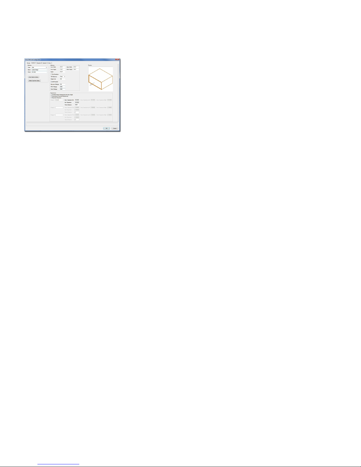
Array Detail and Configuration dialog, continued...
Speaker A, Speaker B, and Speaker C:
(Much of this information is similar to that for AudioBox 2. See pages 9-10 for more information.)
Type: The default for Speaker A is “<Generic>.” For Speakers B and C, the default is “None.” If you
have saved custom or stock speaker types to the Library using the Save to Library button (see
below), they will be listed here, as-well. The only other option is “<Generic>” unless you have saved
custom loudspeaker types to the Library using the Save to Library button (see below). If so, your
additions will be listed here, as-well. Selecting a stored type will populate many of the parameters to
the right. Selecting “None” will mark any already-added loudspeakers for deletion. Choosing the
“Import...” option will cause the “Import Speaker Type” dialog to open, which will allow loudspeaker
data to be imported from appropriately-configured Symbols in Vectorworks® files found in the
“...Libraries/Defaults/Audio Tools/Speakers” folder.
(For Speakers B and C, the rest of the tab is only enabled if you choose a Type other than “None.”.)
Brand and Model: Places for entering the loudspeaker brand and model.
Save to Library (button): Saves key loudspeaker information to an external data file for later use. (See
Type, above.) When this button is clicked, a dialog opens, allowing the assignment of a custom Type
name. Though the default name is [Brand]-[Model], a new name can be entered. (For example, the
Brand and Model in this dialog tab are “Landru Design” and “SB 5000" but the Type is “Sub”)
This Type name is what appears in the Type pop-up. (See pages 18-19 for more information on the
Audio ToolSet 2 Library system.)
Delete From Library (button): Deletes a selected loudspeaker Type from the external data file. (Only
enabled if a non-Generic Type from the Library is selected. See Type, above.)
Front Width, Front Height, Back Width, Back Height, and Depth: Basic dimensions of the
loudspeaker. (All of these dimensions are subject to the same limitations as AudioBox 2. See page 8-
9 for more information. Any changes made to these dimensions will automatically update the “Array
Configuration” tab - and then the model itself once you click “OK.”)
Flip Orientation: Flips the loudspeaker to a "side-ways" orientation.
Tilt Reference: The reference used when setting the tilts of each box in an array - either the front or back
face of the loudspeaker.
Weight (lb) or Weight (kg): The loudspeaker’s weight. If the drawing units are Imperial, this should be
entered in U.S. pounds. If the drawing units are Metric, this should be entered in kilograms. When
the weight is entered in a given unit, the other is automatically calculated and stored.
Self-Powered: A toggle for noting whether the loudspeaker uses an internal or remote amplifier.
Minimum Wattage, RMS Wattage, and Peak Wattage: Places for entering wattage data.
Override Vertical Dispersion(s) with Array Angles: Will force inserted AudioBox 2 objects to use
Angle Relative... angles for each of the three loudspeaker types instead of stated Vertical Dispersion
angles when drawing Dispersion lines. (See Tilt Difference on page 10 and Angle Relative... on
page 15 for more information.)
Asymmetrical Horizontal Dispersion(s): A toggle to enable asymmetrical horizontal dispersions.
Expand Dispersion Features: A toggle for enabling Range notes and Dispersion area information
beyond a simple “Overall”.
Range 1, Range 2, and Range 3: A place for entering notes for each of the 3 Dispersion Ranges (for
example, a frequency range or cross-over point). (These parameters are only enabled if Expand
Dispersion Features is toggled on.)
Horiz. Dispersion Full, Horiz. Dispersion Left, Horiz. Dispersion Right: Horizontal dispersion angles.
“Full” is the sum of “Left” and “Right.” “Left” and “Right” are relative to a loudspeaker facing
“down-screen.” (The “Full” angles can be between 0° and 180°. The Dispersion parameters for
Range 2 and Range 3 are only enabled if Expand Dispersion Features is toggled on.)
Vert. Dispersion: Vertical dispersion angles. (These angles can be between 0° and 180°. The
Dispersion parameters for Range 2 and Range 3 are only enabled if Expand Dispersion Features is
toggled on.)
Throw Distance: The throw distance reference for the dispersion lines. (The Throw Distances for Range
2 and Range 3 are only enabled if Expand Dispersion Features is toggled on.)
p a g e 1 4 o f 1 9
Page 15
A u d i o T o o l S e t 3 . 0
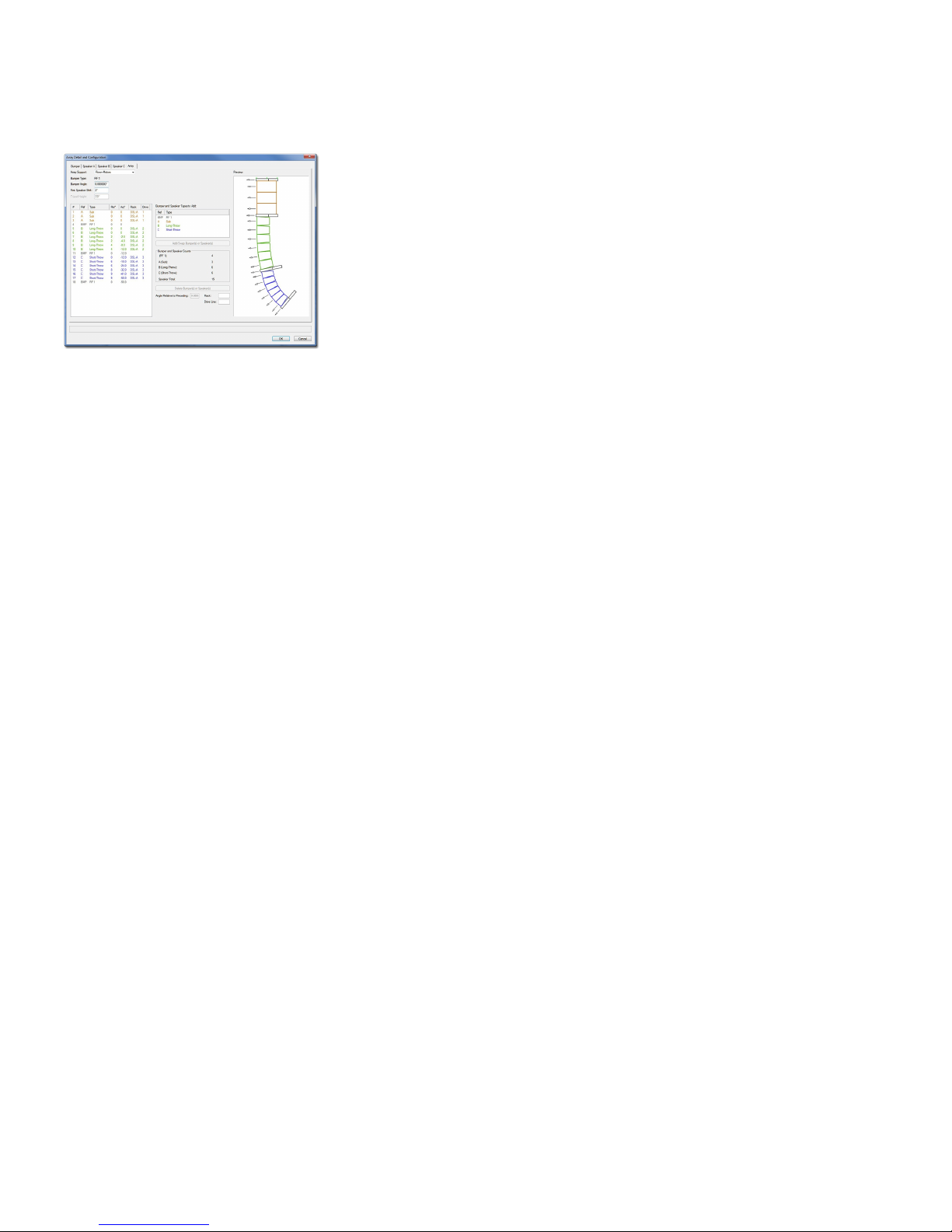
Array Detail and Configuration dialog, continued...
Array Configuration:
Array Support: How the array is to be supported. If “Ground-Stacked” or “Tripod” is chosen, a bumper
or a tripod will become the base for the array and the speakers will “stack” on it. Otherwise, the
speakers “hang” from a bumper.
Bumper Type: The Bumper defined in the “Bumper” tab. If no Type, Brand, or Model information has
been entered, the Bumper Type will be “Generic.”
Bumper Angle: The tilt of the bumper. (Negative values will tilt the bumper and loudspeaker array
down. Positive values will tilt the bumper and loudspeaker array up. Only enabled if an Array
Support option other than “Tripod” is chosen.)
First Speaker Shift: The distance the first speaker (and, as a result, all of the elements) will shift forward
or backward relative to the “parent”/”master” bumper.
Tripod Height: The height from the tripod’s insertion point to the bottom speaker. (Only enabled if the
“Tripod” Array Support is chosen.)
Bumper and Speaker Types to Add: The bumper and speaker(s) defined on the Bumper, Speaker A,
Speaker B, and Speaker C tabs. Only Speaker Types other than “None” are listed. As with the
Bumper Type, if no Type, Brand, or Model information has been entered, the definition’s Type will
be “Generic.”
Add/Swap Bumper(s) or Speaker(s) button: A button to add or swap bumpers or loudspeakers to or into
the array. Bumpers and loudspeakers will be added to (or, swapped into) the Definition list to the left.
(Only enabled if one of the element definitions in the Bumper and Speaker Types to Add list is
selected. Up to 42 elements may be added to a single array.)
Bumper and Speaker Counts: Current totals for each of the bumper and loudspeaker definitions.
Delete Speakers button: A button to delete bumpers and loudspeakers from the array. (Only enabled if
one or more of the bumpers and/or loudspeakers in the Definition list is selected.)
Angle Relative to Preceding: The angle for a selected bumper or loudspeaker relative to the element
(loudspeaker or bumper) immediately above it. For each of the bumpers and/or loudspeakers in the list,
the Definition list will note this relative angle and the actual tilt angle. (Only enabled if the bumper or
one of the loudspeakers in the Definition list is selected. Note: Audio Array 2 will only allow bumpers
and/or loudspeakers to be tilted less than 90° or more than -90°.)
Rack: A place for entering information about the rack driving the selected loudspeaker.
Drive Line: A place for entering information about the drive line feeding signal to the selected
loudspeaker.
p a g e 1 5 o f 1 9
Clicking the Add/Swap Bumper(s) or Speaker(s) button when no bumpers or loudspeakers are selected in
the Definition list to the left will ADD the currently-selected bumper or loudspeaker Type to the array.
Clicking this button when one or more bumpers or loudspeakers are selected in the Definition list to the left
will REPLACE the currently-selected element in the array with the Type selected in the Bumper and
Speaker Types to Add list.
For any of the elements contained in the Definition list, the bumper or loudspeaker in position #1 is closest to
the “parent”/”master” bumper and ascending numbered elements count up or down away from that bumper.
For any of the bumpers or loudspeakers contained in the Definition list, their positions can be changed by
dragging their numbers to other locations in the list.
Any changes made in the Definition list or to the Angle Relative to Preceding value will automatically
update the Preview window.
If AudioArray 2 has already inserted AudioBox 2 or AudioBumper 2 models, clicking “OK” on any of the
“Array Detail and Configuration” dialog tabs will cause the array to be rebuilt automatically.
Page 16
A u d i o T o o l S e t 3 . 0
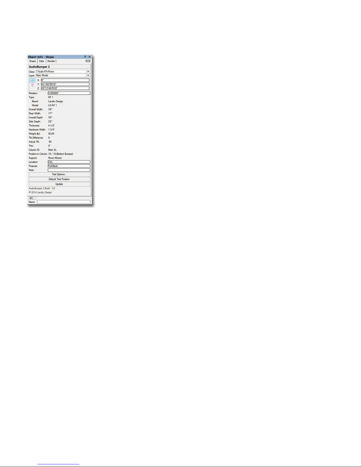
AudioBumper 2 parameters
Class, Layer, X, Y, Z, and Rotation: Settings similar to other Vectorworks® symbols and objects. (“Z” is the distance
from the drawing’s ground plane to the bottom front center of the bumper).
Type: The type of the bumper inserted.
Brand and Model: The bumper brand and model.
Overall Width, Overall Depth, and Thickness: The overall width, depth, and thickness of the bumper.
Rear Width: The width of the rear face the bumper.
Side Depth: The measurement of the side face of the bumper, as measured from the front face.
Hardware Width: The width of the hardware members comprising the bumper.
Weight (lb) or Weight (kg): The bumper weight. If the drawing units are Imperial, this will be shown in U.S. pounds. If
the drawing units are Metric, this will be shown in kilograms.
Tilt Difference: The tilt difference between the selected bumper and the bumper or loudspeaker above it, as determined by
the “parent”/”master” AudioArray 2 object.
Actual Tilt Angle: The actual tilt of the selected bumper.
Trim: The “Z” height of the selected bumper, as measured from the Ground Plane to the bottom front center (the Insertion
Point) of the selected bumper.
Column ID: The name for the column (if any) in which the AudioBumper 2 object is placed. This is also the name for the
AudioArray 2 “parent”/“master’ bumper and the “child”/“slave” bumper.
Position in Column: The bumper’s position in its column, once the AudioBumper 2 object has been inserted or updated by
an AudioArray 2 object.. (“1" is the top loudspeaker or additional bumper.)
Support: The support option for the array to which the bumper belongs.
Location: The bumper location (such as Downstage Left).
Purpose: A place for entering the bumper’s purpose (such as Pull-Back).
Note: A place for entering miscellaneous notes, such as rental source or stock number.
Text Options...: A button to open the “Text Options” dialog, in which text elements are shown, hidden, and/or modified.
(See page 10 for more information).
Default Text Position: A button to return text to its default location. (Only enabled if text has been inserted)
Update (button): Click this button to regenerate the AudioBumper 2 object. You might need to click this if you’re making
changes regarding using Class Attribute settings.
AudioBumper 2 Build: The build number of the AudioBumper 2 Plug-In Object code.
p a g e 1 6 o f 1 9
Page 17
A u d i o T o o l S e t 3 . 0
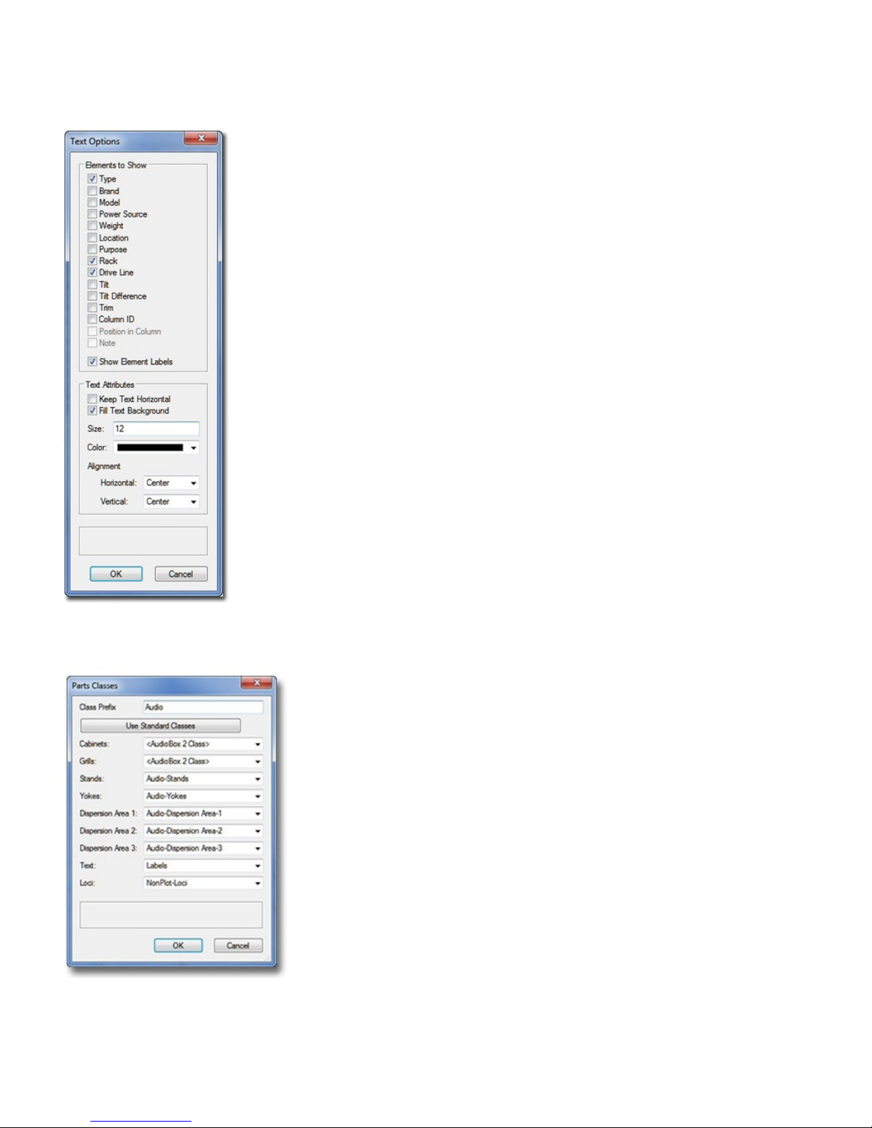
Text Options dialog (AudioBox 2 shown)
Elements to Show:
A list of potential text elements that can be shown as part of each AudioBox 2, AudioArray 2, or AudioBumper 2
instance - "Type," "Brand," "Model," "Power Source," etc. Check the boxes of the elements to be included in the text
block placed on the drawing. Only items appropriate for a given object and/or elements actually containing
information will be enabled.
Show Element Labels: Check the box to include labels for each of the text elements. (“Brand,” “Model,” “Weight,” etc.
Only enabled if any of the “Elements to Show” are checked.)
Text Attributes (only enabled if at least one text element is selected to be shown):
Keep Text Horizontal: Toggle on to keep text horizontal, regardless of the Audio ToolSet 2 object’s rotation angle.
Fill Text Background: Toggle to cause the text block to have an opaque background.
Size: The size of the text element, in points.
Color: A pop-up to let you pick the color of the text element using the Vectorworks® Color Picker.
Horizontal and Vertical Alignment: Pop-ups to let you select text alignment and justification.
The AudioArray 2 and Audio Bumper 2 Text Options dialogs contain different elements to show, but are identical in
functionality.
Parts Classes dialog (AudioBox 2 shown)
Class Prefix: The prefix that will be applied to each suggested Class generated if the “Use Standard Classes”
button is clicked.
Use Standard Classes: A button to populate each of the Class Pop-Ups with suggested Class names, each
(except for “Loci”) with the prefix as entered in the “Class Prefix” box.
Cabinets, Grills, Stands, etc.: Class Pop-Ups specifying the Class to which the given part is assigned. Existing
Classes can be chosen or new Classes can be created on-the-fly. “<AudioBox 2 Class>” signifies the
individual part simply using the given object’s overall Class. By-default, “Loci” are assigned to the
“NonPlot-Loci” Class and all other parts are assigned to the object’s overall Class (the rough equivalent of
leaving the previous Audio ToolSet 2 versions’ “Class Parts...” box un-ticked ).
In the example to the left...
Cabinets and Grills are using the AudioBox 2 object’s overall Class.
Stands, Yokes, Dispersion Area 1, Dispersion Area 2, Dispersion Area 3, and Loci are all assigning the
given parts to Classes generated by clicking the “Use Standard Classes” button.
Text is assigning object text to a custom Class.
The AudioArray 2 Parts Class dialog is identical in functionality.
p a g e 1 7 o f 1 9
Page 18

A u d i o T o o l S e t 3 . 0
Library Notes
Because questions about the Audio ToolSet 2 Library system are the most-asked of all of the inquiries we receive
regarding any of our tools, here are a few “under-the-hood” notes:
The File and Location
The tools simply store information (dimensions, weight, dispersions, etc.) about your speakers and bumpers - not the
model geometry. All of this Library information is stored in a file called "AudioToolSetData.xml." That file is
found in the "…\Libraries\Defaults\Audio Tools" folder - either in your Vectorworks® application folder or in your
User folder structure.
If your installation of Vectorworks® includes the "Speaker" and "Speaker Array" tools, a sample version of that file
might be found in the "...\Libraries\Defaults\Audio Tools" folder, found in your main Application folder. If your
installation does not include those tools, that file in that location does not exist.
The User Folder
If you've not set up a custom User Folder structure, you can find out which folder Vectorworks® is using to store
your Audio ToolSet 2 Library by going to the "User Folders" tab in the [Tools][Options][Vectorworks Preferences…]
dialog. The folder shown, there, will be where the "Libraries" folder structure is stored - which, in-turn holds the
“Audio Tools” folder.
On a Mac, “Libraries” folder is generally hidden unless you press the Option key when choosing the “Go” menu in
the Finder application.
Functionality Prior To Version 3.0
Prior to version 3.0 of these tools, if the sample file existed, the tools automatically created a “User” copy in the
“Audio Tools” folder in your User folder structure the first time one of the tools was used. Then on out, this is the
location where the tools accessed and stored your Library of speakers and bumpers. The sample file was never
checked again. If the sample file did not exist, the tools didn't do anything until you stored your first speaker or
bumper - which created the XML file from-scratch in the User folder. Every time either an AudioBox 2 instance was
touched or inserted or Audio Array 2's “Configure Array...” dialog was opened, the "User" Library file was read and
re-written - in addition to being re-written when you added or deleted a speaker or bumper to or from your library .
p a g e 1 8 o f 1 9
Page 19

A u d i o T o o l S e t 3 . 0
Functionality in Version 3.0 and Beyond
Starting with version 3.0, every time either an AudioBox 2 instance is touched or inserted or Audio Array 2's
“Configuration Array...” dialog is opened, the Library file is read and checked using the following hierarchy:
First: "User" Library in the “User” folder
Second: "Sample" Library in the Application folder
Third: "Old” (version 1) Library
The tools will stop looking with the “highest-priority” Library. In addition to adding or deleting speakers or
bumpers, the Library file is only re-written (or, copied) if certain errors are found and need to be fixed. Any Library
“writing” is done to the “User” folder. Assuming no elements are being added or deleted and the “sample” Library
doesn't contain the checked-for errors and it is the highest-priority Library found, the "User" file is never written.
The one exception to this error checking and fixing has to do with weight. When the Library is simply read (to
populate the various Pop-Up menus), weight units are not considered. When different speakers or bumpers are
selected, though, this these units ARE checked. If weight unit information is missing, you are asked what unit was
intended when the selected element was initially added to the Library and the Library file is written (or, created for
the first time) to your “User” folder. If the correct lb/kg weight system is found for the selected element, no Library
writing is done.
Sharing Library Files
To copy your Audio ToolSet 2 Library from one computer to another, simply find "AudioToolSetData.xml" on the
“source” computer and copy the file to the same place on the “destination” computer (more-than-likely, the “User”
folder).
Two warnings to heed:
1) If there is ANY question about truly wanting to over-write any Library information on the “destination
computer, make sure you save a copy of that file in a safe place.
2) While all versions of the Audio ToolSet 2 tools will be able to read any version of "AudioToolSetData.xml,"
older versions don't recognize the much of the current data and if you “round-trip” the file, that information will
be lost.
p a g e 1 9 o f 1 9
 Loading...