

Land Pride ZT72 User Manual
ZXT & ZT Mower Jack
Assembly Instructions
For ZXT54, ZXT60, ZT60 & ZT72 Zero Turn Mowers
General Information
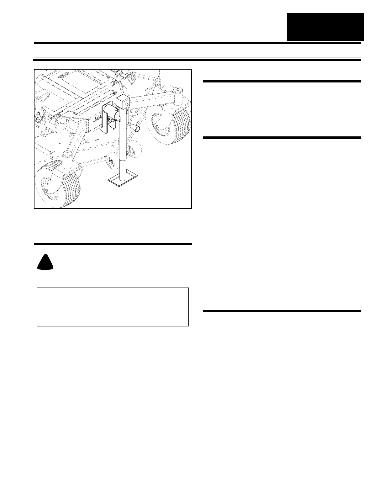
The Land Pride Mower Jack is designed for raising the
front of the mower axle frame and deck to better access
front axle components and deck underside. It is
especially useful for cleaning the deck underside,
accessing cutting blades and making front tire repairs.
Further Assistance
Your dealer wants you to be satisfied with your new
MowerJack. If for any reason you do not understand any
part of this manual or are not satisfied with the service
received, the following actions are suggested:
1. Discuss the matter with your dealership service
manager making sure he is aware of any problems
youmayhaveandthat he has had the opportunity to
assist you.
25819
Mower Jack (ZT Series Mower Shown)
Figure 1
2. If you are still not satisfied, seek out the owner or
general manager of the dealership, explain the
problem and request assistance.
3. For further assistance write to:
Before You Start
Land Pride Service Department
When you see this symbol, the subsequent
instructions and warnings are serious - follow
!
without exception. Your life and the lives of
others depend on it!
IMPORTANT: Before you begin, read these
instructions and check to be sure all parts and tools
are accounted for. Please retain these installation
instructions for future reference and parts ordering
information.
Your Mower Jack is exclusively designed for the Land
Pride ZXT & ZT Series Zero Turn Mowers. Please read
these installation instructions and your Operator’s
Manual thoroughly before beginning. Especially read
information relating to safety concerns.
A separate Parts Manual for your Zero Turn Mower can
be purchased from your dealer or available free of
charge at www.landpride.com. Have model and serial
numbers handy when placing an order.
Manual Part Numbers:
ZXT54 & ZXT60
• Operator’sManual . . . . . . . . . . . . . . . . 357-271M
• Parts Manual . . . . . . . . . . . . . . . . . . . . . 357-271P
ZT60 & ZT72
• Operator’sManual . . . . . . . . . . . . . . . . 357-103M
• Parts Manual . . . . . . . . . . . . . . . . . . . . . 357-103P
Assembly Instructions
These assembly instructions apply to the accessory kit
listed below:
357-209A Mower Jack, ZXT & ZT Series
Adetailedlistingofpartsfor this accessory kit isprovided
on page 2. Use the list as a checklist to inventory parts
received.Please contact your local Land Pride dealer for
any missing hardware.
Tools required
Safety glasses
•
• One 9/16" box end or open end wrench
• Torque wrench with 9/16" socket.
Initial Preparations
1. Park unit on a flat surface and make sure blade
engagement switch is in the down (OFF) position.
2. Spread both control levers fully apart. Stop engine
and remove ignition key.
Manual No. 357-259M
1525 East North Street
P.O. Box 5060
Salina, Ks. 67402-5060
E-mail address
lpservicedept@landpride.com
© Copyright 2009 Printed
03/25/09
1
Land Pride
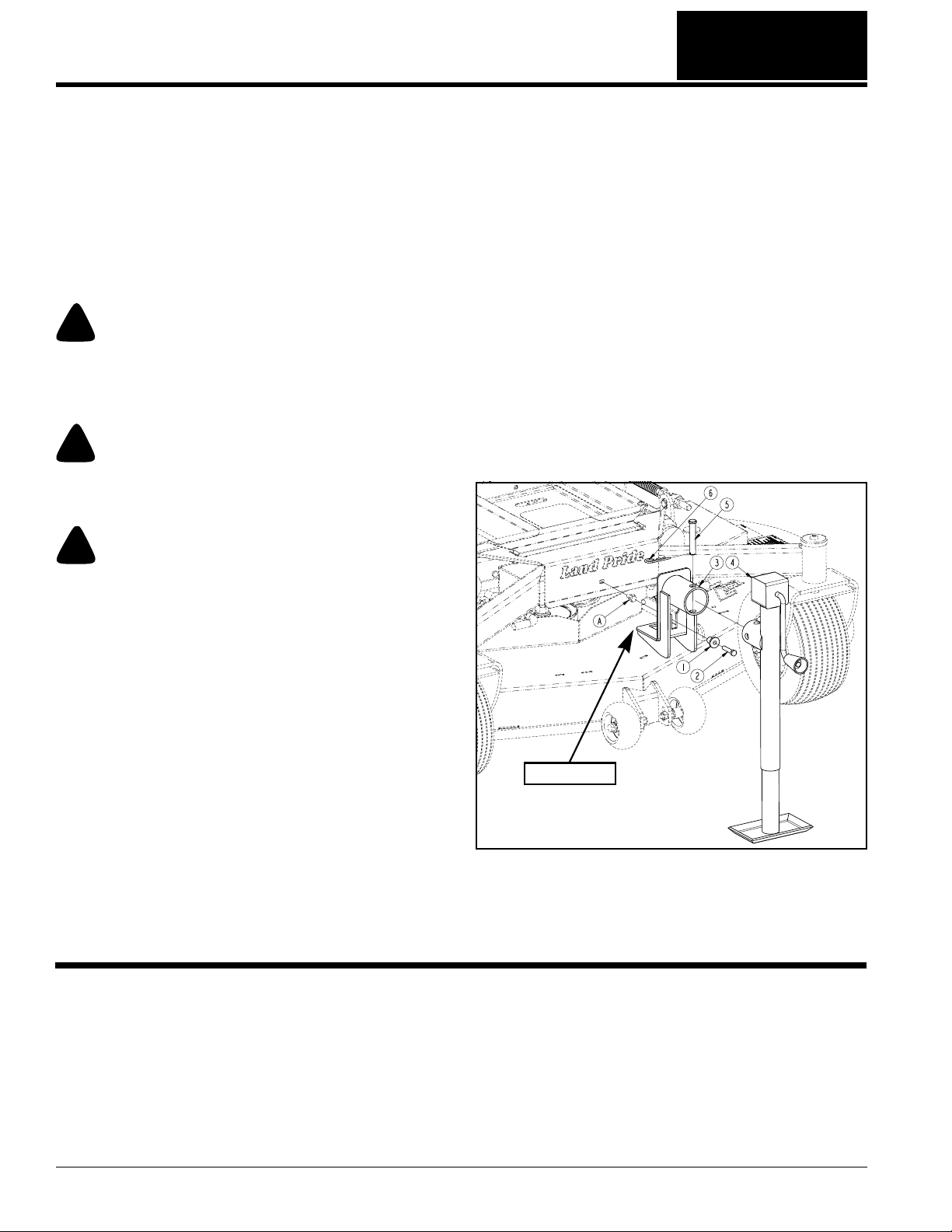
Mower Jack Assembly
Refer to Figure 2:
1. Remove existing 3/8" x 3/4" bolt (A).
2. Attach jack retainer (#1) to mower frame with
3/8"-16 x 1 3/4" GR8 hex head cap screw (#2).
Torque cap screw to 31 ft-lbs.
3. Attach screw jack (#4) to lift bracket (#3) with
5/8" clevis pin (#5) and hair pin cotter (#6).
Mower Jack Operating Instructions
!
Make certain the engine cannot be accidentally started. Shut
engine off and removeignition switch key for maximum safety.
Repairs or maintenance requiring engine power should be
performed by trained personnel only.
Exercise caution when working under the deck as the mower
blades areextremely sharp. Wearingglovesisadvisablewhen
working around or with blades.
For your safety and safety of others, a jacked mower must be
supported properlywith jack stands beforeworking under and
around it. Also the wheels on the ground must be chocked on
both sides to prevent the mower from rolling forward or
backward.
Refer to Figure 2:
1. Park unit on a flat surface and make sure blade
2. Spread both control levers fully apart. Stop engine
3. Chock back and front of rear wheels to prevent
4. Mount lift bracket (#3) onto jack retainer (#1). Make
WARNING
!
WARNING
!
DANGER
engagement switch is in the down (OFF) position.
and remove ignition key.
mower from rolling forward or backward.
sure flange of jack retainer is fully through the lift
bracketslot and that the lift bracket cannot be pulled
off the jack retainer when raised up.
5. Turn hand crank of screw jack to raise lift bracketup
until lifting flange is against mower axle.
6. Continue jacking front of mower up until mower is
slightly higher than what is required for the work
intended.
7. Place jack stands under two to three well spaced
support points at the deck edge.
8. Lower mower frame until all weight is off the jack.
When properly lowered, the deck will be resting on
the jack stands and the mower frame will be resting
on the deck.
9. After completing maintenance, jack mower up until
deck weight is off the jack stands.
10. Remove jack stands and then lower mower weight
onto its front wheels.
11. Removelift bracketand screwjackfromjack retainer.
Store bracket with jack in a convenient location for
future reuse.
12. Remove wheel chocks.
Lifting Flange
25810
Mower Jack Assembly (ZT Series Mower Shown)
Figure 2
Kit No. 357-209A Mower Jack, ZXT & ZT Series
Item Part No. Part Description Qty
Refer to Figure 2:
1 357-503D JACK RETAINER 1
2 802-297C HEX HEAD CAP SCREW 3/8"-16 x 1 3/4" GR8 1
3 357-208H LIFT BRACKET 1
4 890-245C SCREW JACK 2000# 15-30 1
5 805-334C PIN CLEVIS 5/8" x 3 1/2" PLT 1
6 805-032C PIN HAIR COTTER .148 WIRE 1
Corporate Office: P.O. Box 5060
Salina, Kansas 67402-5060 USA
www.landpride.com
ZXT & ZT Mower Jack Assembly Instructions Manual No. 357-259M 03/25/09
2
■
 Loading...