

Page 1
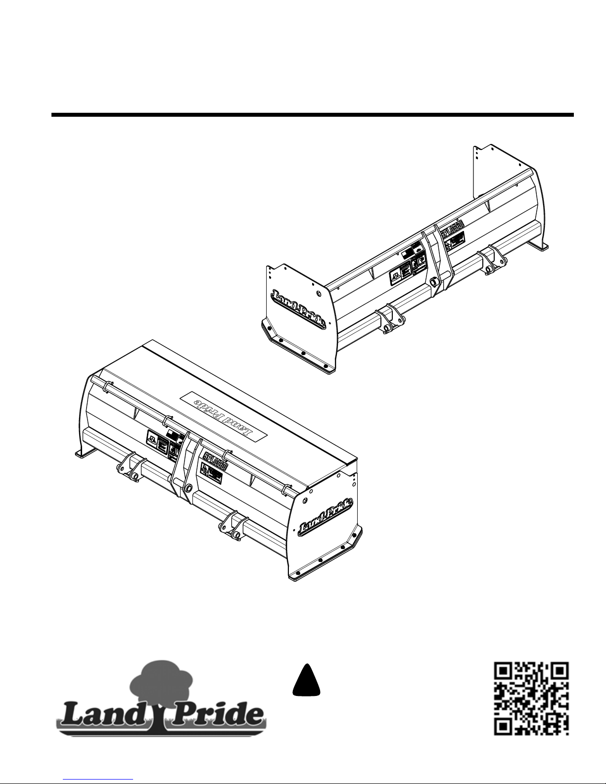
Table of Contents
Snow Pusher
SPL0548 & SPL0560
39546
39713
SPL0560
SPL0560 Shown With Pull Back Option
303-454M
Operator’s Manual
Read the Operator’s Manual entirely. When you
see this symbol, the subsequent instructions and
warnings are serious - follow without exception.
!
Your life and the lives of others depend on it!
Cover photo may show optional equipment
not supplied with standard unit.
© Copyright 2016 Printed
9/07/16
Page 2
Machine Identification
Record your machine details in the log below. If you replace this manual, be sure to transfer this information to the new
manual.
If you, or the dealer, have added Options not originally ordered with the machine, or removed Options that were
originally ordered, the weights and measurements are no longer accurate for your machine. Update the record by
adding the machine weight and measurements provided in the Specifications & Capacities Section of this manual with
the Option(s) weight and measurements.
Model Number
Serial Number
Machine Height
Machine Length
Machine Width
Machine Weight
Delivery Date
First Operation
Accessories
Dealer Contact Information
Name:
Street:
City/State:
Telephone:
Email:
!
WARNING: Cancer and reproductive harm - www.P65Warnings.ca.gov
Page 3

Table of Contents
Table of Contents
Important Safety Information . . . . . . . . . . . . . 1
Safety at All Times . . . . . . . . . . . . . . . . . . . . . . . . . 1
Look For The Safety Alert Symbol . . . . . . . . . . . . . . 1
Safety Labels . . . . . . . . . . . . . . . . . . . . . . . . . . . . . 4
Introduction . . . . . . . . . . . . . . . . . . . . . . . . . . . 5
Application . . . . . . . . . . . . . . . . . . . . . . . . . . . . . . . 5
Using This Manual . . . . . . . . . . . . . . . . . . . . . . . . . . 5
Terminology . . . . . . . . . . . . . . . . . . . . . . . . . . . . . 5
Definitions . . . . . . . . . . . . . . . . . . . . . . . . . . . . . . 5
Owner Assistance . . . . . . . . . . . . . . . . . . . . . . . . . . 5
Serial Number . . . . . . . . . . . . . . . . . . . . . . . . . . . 5
Further Assistance . . . . . . . . . . . . . . . . . . . . . . . . 5
Section 1: Options & Accessory Set-up . . . . 6
Tractor Requirements . . . . . . . . . . . . . . . . . . . . . . . 6
Torque Requirements . . . . . . . . . . . . . . . . . . . . . . . 6
Tractor Shutdown Procedures . . . . . . . . . . . . . . . . . 6
Dealer Preparations . . . . . . . . . . . . . . . . . . . . . . . . 6
Pull Back (Optional) . . . . . . . . . . . . . . . . . . . . . . . . 7
Orange Markers (Accessory) . . . . . . . . . . . . . . . . . . 7
Steel Blade (Optional) . . . . . . . . . . . . . . . . . . . . . . . 8
Poly Blade (Optional) . . . . . . . . . . . . . . . . . . . . . . . 8
Hook-up With BX Quick Hitch . . . . . . . . . . . . . . . . . 9
Unhook With BX Quick Hitch . . . . . . . . . . . . . . . . . . 9
Hook-up Without BX Quick Hitch . . . . . . . . . . . . . . 10
Unhook Without BX Quick Hitch . . . . . . . . . . . . . . 11
Section 2: Operating Procedures . . . . . . . . . 12
Operator’s Responsibilities . . . . . . . . . . . . . . . . . . 12
Safety Information . . . . . . . . . . . . . . . . . . . . . . . . . 12
Transporting . . . . . . . . . . . . . . . . . . . . . . . . . . . . . 13
General Operating Instructions . . . . . . . . . . . . . . . 13
Section 3: Maintenance . . . . . . . . . . . . . . . . . 14
Maintenance . . . . . . . . . . . . . . . . . . . . . . . . . . . . . 14
Skid Shoes . . . . . . . . . . . . . . . . . . . . . . . . . . . . . . 14
Steel Blade (Optional) . . . . . . . . . . . . . . . . . . . . . . 15
Poly Blade (Optional) . . . . . . . . . . . . . . . . . . . . . . 16
Preparation . . . . . . . . . . . . . . . . . . . . . . . . . . . . 16
Reverse Poly Blade . . . . . . . . . . . . . . . . . . . . . . 16
Replace Poly Blade . . . . . . . . . . . . . . . . . . . . . . 16
Long Term Storage . . . . . . . . . . . . . . . . . . . . . . . . 17
Section 4: Specifications & Capacities . . . . 18
Section 5: Features & Benefits . . . . . . . . . . . 19
Section 6: Torque Values Chart . . . . . . . . . . 20
Section 7: Warranty . . . . . . . . . . . . . . . . . . . . 21
© Copyright 2016 All rights Reserved
Land Pride provides this publication “as is” without warranty of any kind, either expressed or implied. While every precaution has been taken in the
preparation of this manual, Land Pride assumes no responsibility for errors or omissions. Neither is any liability assumed for damages resulting from the use
of the information contained herein. Land Pride reserves the right to revise and improve its products as it sees fit. This publication describes the state of this
product at the time of its publication, and may not reflect the product in the future.
All other brands and product names are trademarks or registered trademarks of their respective holders.
SPL0548 & SPL0560 Snow Pusher 303-454M
Land Pride is a registered trademark.
Printed in the United States of America.
9/07/16
Page 4

Page 5
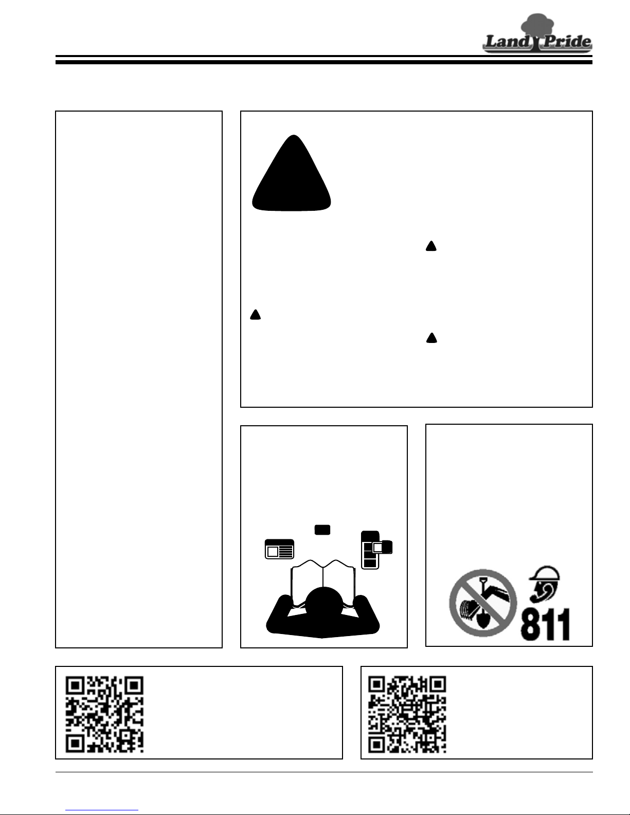
Table of Contents
Important Safety Information
Important Safety Information
These are common practices that may or may not be applicable to the products described in
this manual.
Safety at All Times
Thoroughly read and understand
the instructions given in this
manual before operation. Refer to
the “Safety Label” section, read all
instructions noted on them.
Do not allow anyone to operate
this attachment who has not fully
read and comprehended this
manual and who has not been
properly trained in the safe
operation of the attachment.
The operator must not use drugs
or alcohol as they can change the
alertness or coordination of that
person while operating equipment.
The operator should, if taking overthe-counter drugs, seek medical
advice on whether he/she can
safely operate the equipment.
The operator should be familiar
with all functions of the tractor and
attachment, and be able to handle
emergencies quickly.
Make sure all guards and shields
are in place and secured before
operating attachment.
Keep all bystanders away from
equipment and work area.
Start tractor from the driver’s seat
with hydraulic controls in neutral.
Operate attachment and controls
from the driver’s seat only.
Never dismount from a moving
tractor or leave tractor unattended
with engine running.
Do not allow anyone to stand
between tractor and attachment
while hooking-up.
Keep hands, feet, and clothing
away from power-driven parts.
Watch out for objects overhead
and along side such as wires,
trees, fences, buildings, etc., while
operating and transporting tractor.
Detach and store attachment in an
area where children normally do
not play. Secure attachment by
using blocks and supports.
Look For The Safety Alert Symbol
The SAFETY ALERT SYMBOL indicates there is a
potential hazard to personal safety involved and extra
safety precaution must be taken. When you see this
symbol, be alert and carefully read the message that
follows it. In addition to design and configuration of
!
Be Aware of
Signal Words
A Signal word designates a degree or
level of hazard seriousness. The
signal words are:
!
DANGER
Indicates an imminently hazardous
situation which, if not avoided, will
result in death or serious injury. This
signal word is limited to the most
extreme situations, typically for
machine components that, for
functional purposes, cannot be
guarded.
For Your Protection
Thoroughly read and understand
the “Safety Label” section, read
all instructions noted on them.
equipment, hazard control, and accident prevention are
dependent upon the awareness, concern, prudence, and
proper training of personnel involved in the operation,
transport, maintenance, and storage of equipment.
!
WARNING
Indicates a potentially hazardous
situation which, if not avoided, could
result in death or serious injury, and
includes hazards that are exposed
when guards are removed. It may also
be used to alert against unsafe
practices.
!
CAUTION
Indicates a potentially hazardous
situation which, if not avoided, may
result in minor or moderate injury. It
may also be used to alert against
unsafe practices.
Avoid Underground
Utilities
Dig Safe, Call 811 (USA).
Always contact your local utility
companies (electrical, telephone,
gas, water, sewer, and others)
before digging so that they may
mark the location of any
underground services in the area.
Be sure to ask how close you can
work to the marks they positioned.
Parts Manual QR Locator
The QR (Quick Reference) code on the
cover and to the left will take you to the
Parts Manual for this equipment.
Download the appropriate App on your
smart phone, open the App, point your
phone on the QR code and take a picture.
9/07/16
Dealer QR Locator
The QR code on the left will
link you to available dealers
for Land Pride products.
Refer to Parts Manual QR
Locator on this page for
detailed instructions.
SPL0548 & SPL0560 Snow Pusher 303-454M
1
Page 6
Table of Contents
Important Safety Information
These are common practices that may or may not be applicable to the products described in
this manual.
Tractor Shutdown
And Storage
Before leaving operator’s
seat:
If engaged, disengage PTO.
Lower attachment to ground or
onto support blocks.
Put tractor in park or set park
brake, turn off engine, and remove
switch key to prevent unauthorized
starting.
Wait for all components to come to
a complete stop before leaving the
operator’s seat.
Detach and store attachment in an
area where children normally do
not play. Secure attachment using
blocks and supports.
OFF
R
E
M
OV
E
Transport
Machinery Safely
Comply with state and local laws.
Use towing vehicle and trailer of
adequate size and capacity.
Secure equipment towed on a
trailer with tie downs and chains.
Sudden braking can cause a trailer
to swerve and upset. Reduce
speed if trailer is not equipped with
brakes.
Avoid contact with any over head
utility lines or electrically charged
conductors.
Engage park brake when stopped
on an incline.
Maximum transport speed for an
attached implement is 20 mph. DO
NOT EXCEED. Never travel at a
speed which does not allow
adequate control of steering and
stopping. Some rough terrains
require a slower speed.
As a guideline, use the following
maximum speed weight ratios for
an attached implement:
20 mph when weight of attached
implement is less than or equal to
the weight of machine towing the
implement.
10 mph when weight of attached
implement exceeds weight of
machine towing implement but
not more than double the weight.
IMPORTANT: Do not tow a load
that is more than double the weight
of the machine towing the load.
Use A Safety Chain
A safety chain will help control
drawn machinery should it
separate from the tractor drawbar.
Use a chain with the strength
rating equal to or greater than the
gross weight of the towed
machinery.
Attach the chain to the tractor
drawbar support or other specified
anchor location. Allow only
enough slack in the chain to
permit turning.
Do not use safety chain for towing.
Practice Safe Maintenance
Understand procedure before doing
work. Use proper tools and
equipment, refer to Operator’s
Manual for additional information.
Work in a clean dry area.
Lower attachment to the ground
and follow all shutdown procedures
before leaving the operator’s seat to
perform maintenance.
Allow equipment to cool before
working on it.
Disconnect battery ground cable (-)
before servicing or adjusting
electrical systems or before welding
on attachment.
Do not grease or oil attachment
while it is in operation.
Inspect all parts. Make certain
parts are in good condition &
installed properly.
Replace parts on this attachment
with genuine Land Pride parts only.
Do not alter this attachment in a
way which will adversely affect its
performance.
Remove buildup of grease, oil, or
debris.
Remove all tools and unused parts
from equipment before operation.
SPL0548 & SPL0560 Snow Pusher 303-454M
2
9/07/16
Page 7

Table of Contents
Important Safety Information
These are common practices that may or may not be applicable to the products described in
this manual.
Prepare for Emergencies
Be prepared if a fire starts.
Keep a first aid kit and fire
extinguisher handy.
Keep emergency numbers for
doctor, ambulance, hospital, and
fire department near phone.
911
Wear
Protective Equipment
Wear protective clothing and
equipment appropriate for the job
such as safety shoes, safety
glasses, hard hat, and ear plugs.
Clothing should fit snug without
fringes and pull strings to avoid
entanglement with moving parts.
Prolonged exposure to loud noise
can cause hearing impairment or
hearing loss. Wear suitable
hearing protection such as
earmuffs or earplugs.
Operating equipment safely
requires the operator’s full
attention. Avoid wearing radio
headphones while operating
machinery.
Avoid High Pressure
Fluid Hazards
Escaping fluid under pressure can
penetrate the skin causing serious
injury.
Avoid the hazard by relieving
pressure before disconnecting
hydraulic lines or performing work
on the system.
Make sure all hydraulic fluid
connections are tight and all
hydraulic hoses and lines are in
good condition before applying
pressure to the system.
Use a piece of paper or
cardboard, NOT BODY PARTS, to
check for suspected leaks.
Wear protective gloves and safety
glasses or goggles when working
with hydraulic systems.
DO NOT DELAY. If an accident
occurs, see a doctor familiar with
this type of injury immediately. Any
fluid injected into the skin or eyes
must be treated within
a few hours or
gangrene may
result.
Use Safety
Lights and Devices
Slow moving tractors,
self-propelled equipment, and
towed implements can create a
hazard when driven on public
roads. They are difficult to see,
especially at night.
Flashing warning lights and turn
signals are recommended
whenever driving on public roads.
Use Seat Belt and ROPS
Operate only tractors equipped
with a Roll-Over Protective
Structure (ROPS) and seat belt.
Keep folding ROPS in the “locked
up” position at all times.
Fasten seat belt snugly and
securely to help protect against
serious injury or death from falling
and machine overturn.
Wear protective equipment such
as a hard hat, safety shoes, safety
glasses, and ear plugs.
Keep Riders Off
Machinery
Never carry riders or use
machinery as a person lift.
Riders obstruct operator’s view.
Riders could be struck by foreign
objects or thrown from the
equipment.
Never allow children to operate
machinery.
9/07/16
SPL0548 & SPL0560 Snow Pusher 303-454M
3
Page 8
Important Safety Information
39713
39713
39713
Table of Contents
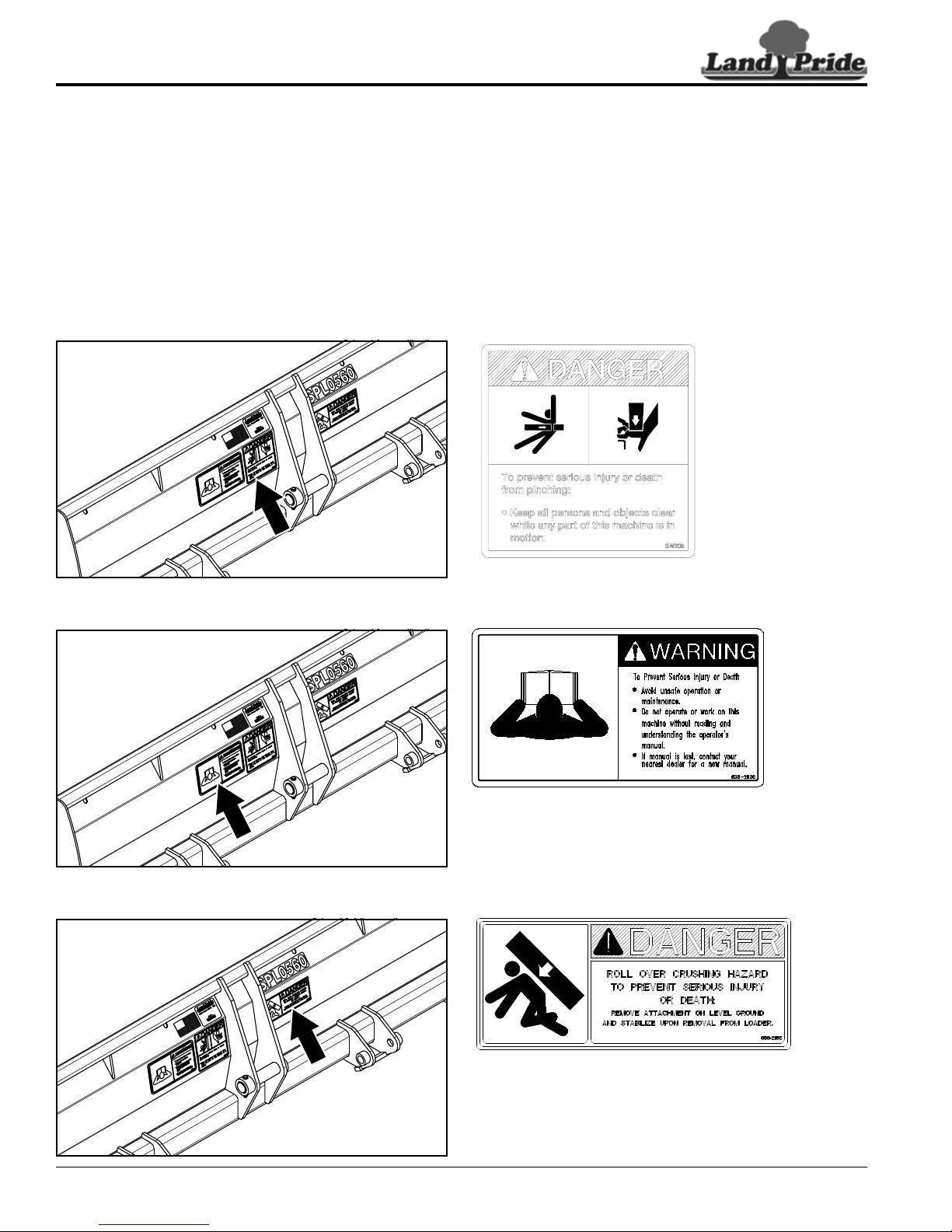
Safety Labels
Your Snow Pusher comes equipped with all safety labels in
place. They are designed to help you safely operate your
attachment. Read and follow their directions.
1. Keep all safety labels clean and legible.
2. Refer to this section for proper label placement. Replace all
damaged or missing labels. Order new labels from your
nearest Land Pride dealer. To find your nearest dealer, visit
our dealer locator at www.landpride.com.
3. Some new equipment installed during repair requires safety
labels to be affixed to the replaced component as specified
by Land Pride. When ordering new components make sure
the correct safety labels are included in the request.
4. Refer to this section for proper label placement.
To install new labels:
a. Clean surface area where label is to be placed.
b. Spray soapy water onto the cleaned area.
c. Peel backing from label and press label firmly onto the
surface.
d. Squeeze out air bubbles with edge of a credit card or
with a similar type of straight edge.
838-112C
Danger: Pinching Hazard
838-293C
Warning: Read & Understand Manual
SPL0548 & SPL0560 Snow Pusher 303-454M
4
858-215C
Danger: Roll Over Crushing Hazard
9/07/16
Page 9
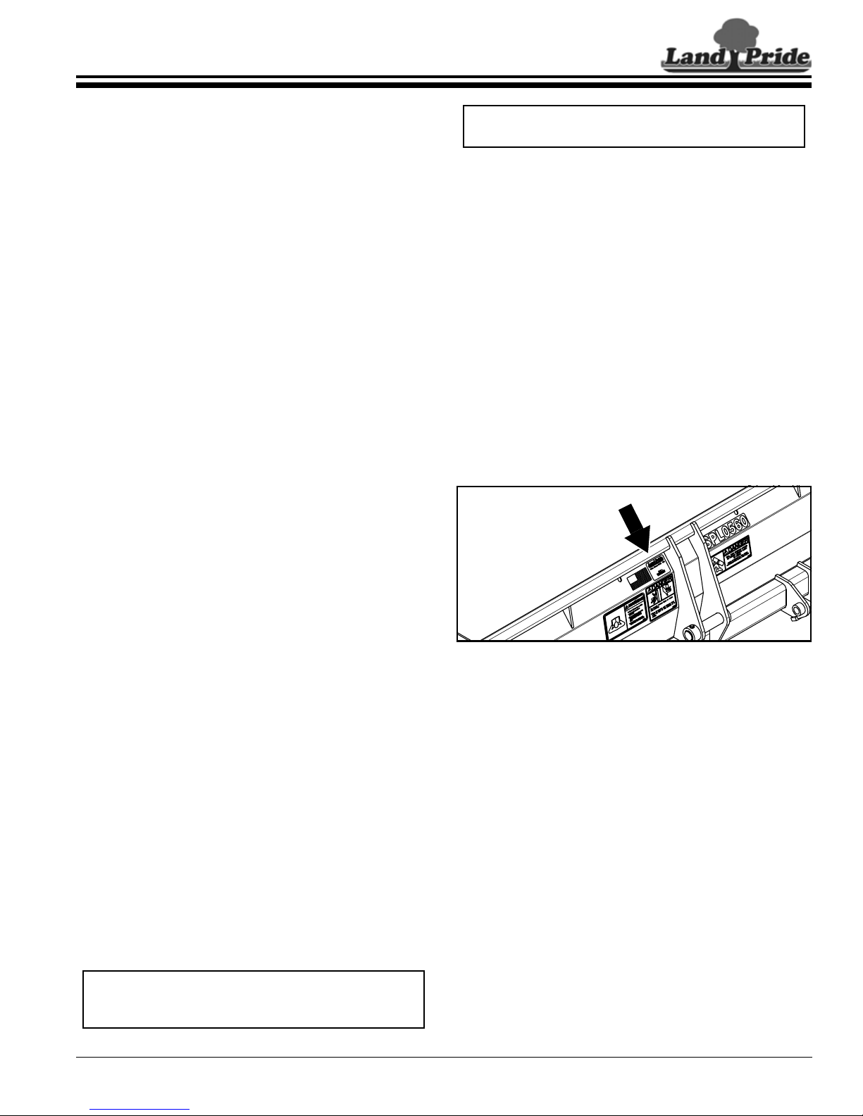
Table of Contents
NOTE: A special point of information that the
operator should be aware of before continuing.
39713
IMPORTANT: A special point of information related
to the following topic. Land Pride’s intention is this
information must be read & noted before continuing.
Introduction
Introduction
Land Pride welcomes you to the growing family of new
product owners.
This Snow Pusher has been designed with care and built
by skilled workers using quality materials. Proper
assembly, maintenance, and safe operating practices will
help you get years of satisfactory use from this
attachment.
Application
Land Pride’s SPL05 Series Snow Pushers are available
in popular sizes to fit your 60 and 70 BX tractor loader
equipped with or without a BX Quick Hitch. They are
designed to push snow and other loose materials straight
ahead without leaving windrows on the side or damaging
the pavement below when using the optional poly snow
blade.
The 05 Series is manufactured in 48" and 60" widths with
12 Ga. moldboard and 18" tall side panels.
The SPL05 Snow Pushers feature replaceable skid
shoes. The Snow Pushers have an optional 3/8" X 4"
steel cutting edge or optional 1/2" X 6" poly cutting edge.
The poly cutting edge helps prevent marking and other
damage to surfaces. Another optional feature of these
Snow Pushers is the pull back blade. The pull back blade
is great for pulling snow back from structures such as
garage doors. Orange markers are available as an
accessory to assist in locating the outer ends of the Snow
Pusher. The orange markers can not be used in
conjunction with the pull back option.
See “Specifications & Capacities” on page 18 and
“Features & Benefits” on page 19 for additional
information and performance enhancing options.
Owner Assistance
The Online Warranty Registration should be completed
by the dealer at the time of purchase. This information is
necessary to provide you with quality customer service.
The parts on your Snow Pusher have been specially
designed by Land Pride and should only be replaced with
genuine Land Pride parts. Contact a Land Pride dealer if
customer service or repair parts are required. Your Land
Pride dealer has trained personnel, repair parts, and
equipment needed to service the attachment.
Serial Number
Model No. _____________Serial No. _______________
For quick reference and prompt service, record model
and serial number in the spaces provided above and
again on warranty page 21. Always provide model
number and serial number when ordering parts and in all
correspondences with your Land Pride dealer. Refer to
Figure 1 for location of your serial number plate.
Using This Manual
This Operator’s Manual is designed to help familiarize
•
you with safety, assembly, operation, adjustments,
troubleshooting, and maintenance. Read this manual
and follow the recommendations to help ensure safe
and efficient operation.
• The information contained within this manual was
current at the time of printing. Some parts may change
slightly to assure you of the best performance.
• To order a new Operator’s or Parts Manual, contact
your authorized dealer. Manuals can also be
downloaded, free-of-charge, from our website at
www.landpride.com
Terminology
“Right” or “Left” as used in this manual is determined by
facing the direction the machine will operate while in use
unless otherwise stated.
Definitions
Serial Number Plate Location
Figure 1
Further Assistance
Your dealer wants you to be satisfied with your new Snow
Pusher. If for any reason you do not understand any part
of this manual or are not satisfied with the service
received, the following actions are suggested:
1. Discuss the matter with your dealership service
manager making sure that person is aware of any
problems you may have and has had the opportunity
to assist you.
2. If you are still not satisfied, seek out the owner or
general manager of the dealership, explain the
problem, and request assistance.
3. For further assistance write to:
Land Pride Service Department
1525 East North Street
P.O. Box 5060
Salina, Ks. 67402-5060
E-mail address
9/07/16
SPL0548 & SPL0560 Snow Pusher 303-454M
5
Page 10
Section 1: Options & Accessory Set-up
!
CAUTION
NOTE: Accessories are easier to attach after
hooking-up Snow Pusher to a tractor front loader.
Refer to “Hook-up With BX Quick Hitch” on page 9
or “Hook-up Without BX Quick Hitch” on page 10.
!
WARNING
IMPORTANT: Tractors outside the listed horsepower
range must not be used. Higher horsepower tractors
can damage the attachment.
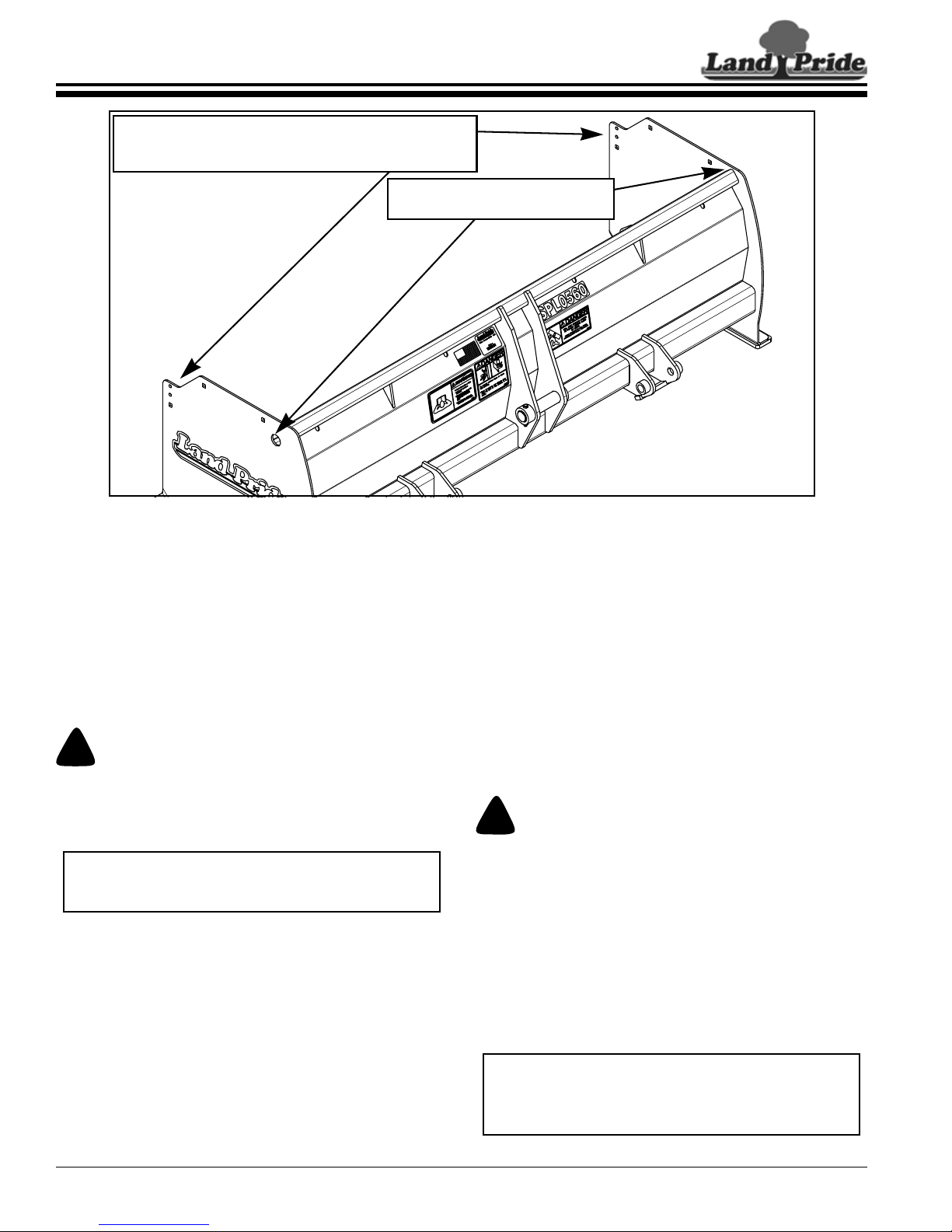
Lifting slots for picking up the
Snow Pusher with lift chains.
Attach 2 additional lift chains to the front of the
side plate to help keep unit from flipping forward
suddenly while lifting the unit to its upright position.
39713
Section 1: Options & Accessory Set-up
Table of Contents
Tractor Requirements
The Snow Pusher is designed to attach to tractor loaders
equipped with or without a BX Quick Hitch. The following
requirements must be met:
Hitch type . . . . Kubota BX front loader with or without
BX6315 Quick Hitch
Horsepower range . . . . . . . . . . . . . . . . . . 28 hp max.
Maximum tractor weight . . . . . . . . . . . . . . . . 1,800 lbs
Maximum tractor lift capacity at pivot pins . . . 800 lbs
Rear ballast weights may be required to maintain steering
control and tractor stability while lifting and transporting
heavy loads. Be sure to consult your tractor Operator’s
Manual to determine whether or not to add ballast.
Torque Requirements
Refer to “Torque Values Chart” on page 20 to for
correct torque values when tightening hardware.
Tractor Shutdown Procedures
The following are proper shutdown procedures. Always
follows these procedures before dismounting tractor.
1. Reduce tractor engine speed to an idle.
2. If PTO is engaged, disengage PTO.
3. Park tractor and attachment on level, solid ground.
4. Lower attachment to ground or onto support blocks.
SPL0548 & SPL0560 Snow Pusher 303-454M
6
Dealer Preparations
Figure 1-1
5. Put tractor in park or set park brake, turn off engine,
and remove switch key to prevent unauthorized
starting.
6. Wait for all components to come to a complete stop
before leaving the operator’s seat.
7. Use steps, grab-handles and skid-resistant surfaces
when getting on and off the tractor.
Dealer Preparations
Ensure that the intended tractor conforms to the
requirements stated under the heading “Tractor
Requirements” on this page.
Refer to Figure 1-1:
Keep clear. The Snow Pusher can flip suddenly causing
serious bodily injury while lifting unit from the crate.
1. The Snow Pusher is shipped on its back. Cut corner
posts of shipping crate and remove top frame.
2. Attach lifting chains to slots in the side panels.
3. Stabilize unit against flipping by attaching additional
chains to the holes at the front of the side panels.
4. Using a hoist, fork lift, or other lifting device, slowly lift
Snow Pusher until it has rotated upright.
5. Lower unit slowly until resting on its skid shoes.
9/07/16
Page 11
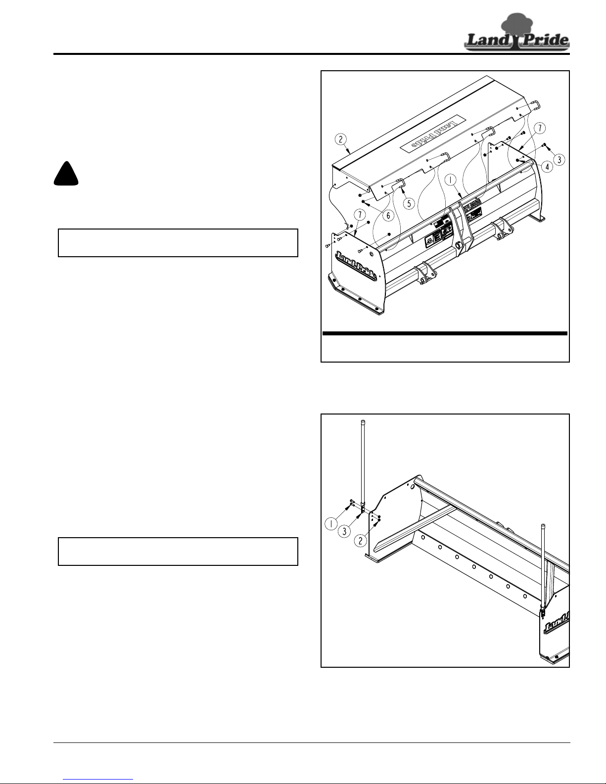
Table of Contents
!
CAUTION
IMPORTANT: The flanges on the pullback may need
to be pulled together to fit unit between side panels.
NOTE: Orange marker package cannot be used
with pull back option.
Part No. Description
303-450A PULL BACK ASSEMBLY 48"
303-449A PULL BACK ASSEMBLY 60"
39714
39729
Section 1: Options & Accessory Set-up
Pull Back (Optional)
Refer to Figure 1-2:
Land Pride offers an optional pull back (#2). It is shipped
complete with mounting hardware (#3, #4, #5, & #6). This
kit will allow operator to pull snow away from garage
doors and other objects while backing up. See Figure 1-2
for part numbers and descriptions.
Be careful not to pinch fingers, hands, or other body
extremities between pull back and Snow Pusher as unit is
attached to the Snow Pusher.
1. Attach back side of pull back to the inside of
moldboard (#1) with 3/8"-16 u-bolts (#5) and hex
whiz nuts (#6). Do not tighten whiz nuts at this time.
2. Attach ends of pull back (#2) to the inside of side
panels (#7) with 3/8"-16 x 1" GR5 carriage bolts (#3)
and hex whiz nuts (#4).
3. Tighten hex whiz nuts (#4 & #6) to the correct torque.
Orange Markers (Accessory)
Part No. 323-026A
Refer to Figure 1-3:
Land Pride offers 28" high orange markers that can be
bolted to the side panels. These assist in locating outer
ends of the Snow Pusher when approaching buildings,
trees, poles, and other obstacles that can damage the
attachment, tractor, or obstacles the Snow Pusher
comes in contact with.
1. Attach orange marker (#3) to the right-hand side
panel with 5/16"-18 x 1" GR5 hex head bolts (#1) and
hex nylock nuts (#2). Tighten nylock nuts to the
correct torque.
2. Repeat step 1 for the left-hand side panel.
Pull Back Option
Figure 1-2
9/07/16
Orange Marker Assembly
Figure 1-3
SPL0548 & SPL0560 Snow Pusher 303-454M
7
Page 12
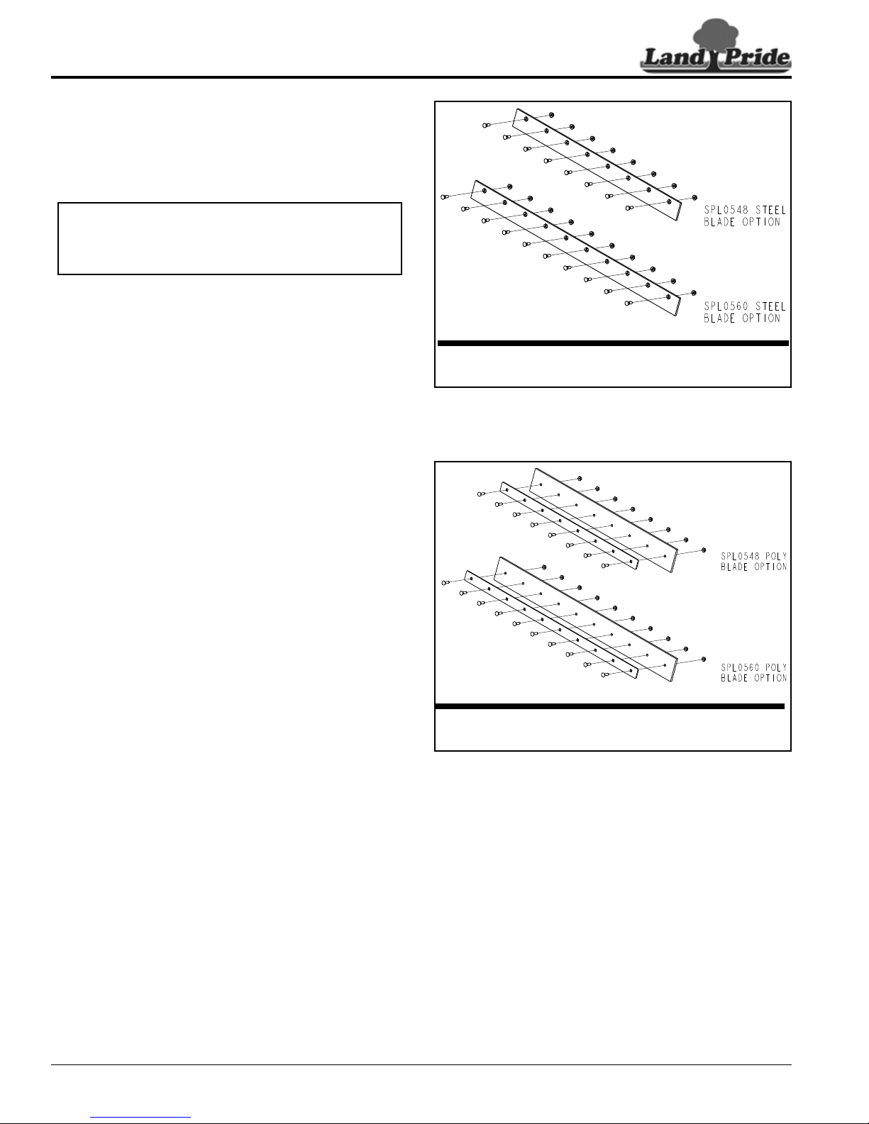
Table of Contents
39715
Item Part No.Description
303-441A SP STEEL BLADE ASSEMBLY 48"
303-442A SP STEEL BLADE ASSEMBLY 60"
39716
Part No. Description
303-453A 48" POLY BLADE ASSEMBLY
303-452A 60" POLY BLADE ASSEMBLY
IMPORTANT: Steel blades are not designed to move
soil, rock, and other compacted surfaces. They can
cause structural damage to the terrain and Snow
Pusher if not used with care.
Section 1: Options & Accessory Set-up
Steel Blade (Optional)
Refer to Figure 1-4:
Land Pride offers optional steel blade kits complete with
mounting hardware. See Figure 1-4 for part numbers and
descriptions.
Steel Blade Option
Figure 1-4
Poly Blade (Optional)
Refer to Figure 1-5:
Land Pride offers optional poly blade kits complete with
mounting hardware. See Figure 1-5 for part numbers and
descriptions.
Poly Blade Option
Figure 1-5
SPL0548 & SPL0560 Snow Pusher 303-454M
8
9/07/16
Page 13
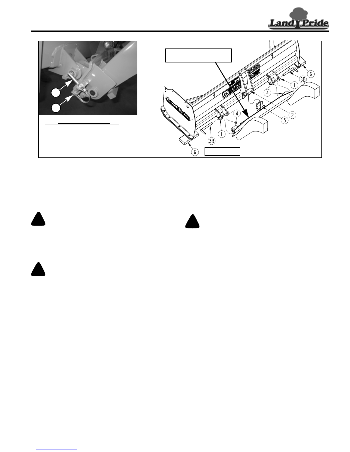
Table of Contents
!
DANGER
!
CAUTION
!
WARNING
Detail A
3B
3A
39717
Kubota’s Original Quick
Hitch Option No. BX6315
See Detail A
Section 1: Options & Accessory Set-up
Hook-up With Kubota’s Original Quick Hitch
Figure 1-6
Hook-up With BX Quick Hitch
Follow instructions below if hooking Snow Pusher to
“Kubota Original Quick Hitch” Option No. BX6315. If
hooking the Snow Pusher directly to the front loader, skip
to “Hook-up Without BX Quick Hitch” on page 10.
7. Insert hitch pins (#3B) in clevises (#1) and lower
quick hitch bushings (#4).
8. Secure hitch pins (#3B) with wire retaining
pins (#3A) as shown in Detail A.
Unhook With BX Quick Hitch
A crushing hazard exists when hooking-up an attachment. Do
not allow anyone to stand between tractor and attachment
while approaching attachment. Do not operate lift controls
while someone is near tractor, loader arms, and/or
attachment.
Make sure the Snow Pusher is properly attached to Kubota’s
quick hitch to keep it from coming loose and falling. The Snow
Pusher’s center hitch pin must be cradled in the quick hitch
j-hook and clevises must be pinned to the quick hitch with
hitch pins. Hitch pins must be secured with retaining pins.
Refer to Figure 1-6:
1. Check for and remove any debris in the hitch point
areas before hooking up the Snow Pusher.
2. Remove retaining pins (#3A) and hitch pins (#3B).
3. Rotate top of quick hitch forward and lower loader
arms until j-hook (#5) is positioned at a height to fit
under center hitch pin (#2).
4. Slowly drive tractor forward until j-hook (#5) is
positioned under center hitch pin (#2).
5. Slowly raise loader arms and rotate top of quick hitch
back until center hitch pin (#2) is fully seated in
j-hook (#5) and holes in bushings (#4) are in-line with
clevis pin holes (#1).
6. Shut tractor down properly. Refer to “Tractor
Shutdown Procedures” on page 6 without lowering
attachment to ground.
The Snow Pusher is back heavy and can tip over backwards
easily once unhooked. Always unhook unit on level ground
with support blocks under the skid shoes at the back to tip the
unit forward. Never unhook unit with back of unit facing
downhill.
Refer to Figure 1-6:
1. See “Long-Term Storage” on page 17 when parking
attachment for long periods or at the end of the
working season.
2. Reduce tractor engine speed to an idle and park
tractor and Snow Pusher on level, solid ground.
3. Lower Snow Pusher until the back of skid shoes are
resting on support blocks (#6) and front of skid shoes
are resting on the ground.
4. Shut tractor down properly. Refer to “Tractor
Shutdown Procedures” on page 6.
5. Remove retaining pins (#3A) and hitch pins (#3B)
from lower clevises (#1).
6. Return to the tractor, start engine, and slowly lower
loader arms while rotating top of quick hitch forward
until j-hook (#5) is below center hitch pin (#2).
7. Carefully back away from the Snow Pusher and
rotate top of quick hitch back until vertical.
8. Shut tractor down properly before dismounting.
9. Replace hitch pins (#3B) in quick hitch bushings (#4)
and secure with retaining pins (#3A).
9/07/16
SPL0548 & SPL0560 Snow Pusher 303-454M
9
Page 14
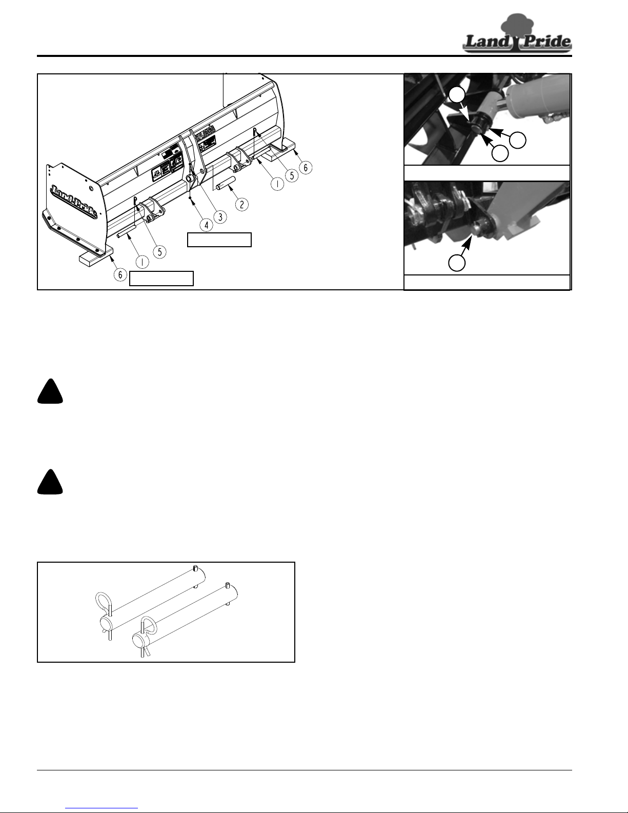
Table of Contents
!
DANGER
!
CAUTION
35848
1
Detail B
35851
35850
Detail A
2
3
4
39718
See Detail A
See Detail B
Section 1: Options & Accessory Set-up
Hook-up Without Kubota’s Original Quick Hitch
Figure 1-7
Hook-up Without BX Quick Hitch
If hooking Snow Pusher to “Kubota’s Original Quick
Hitch”, see “Hook-up With BX Quick Hitch” on page 9.
Otherwise, continue with instructions below.
A crushing hazard exists when hooking-up an attachment. Do
not allow anyone to stand between tractor and attachment
while approaching attachment. Do not operate lift controls
while someone is near tractor, loader arms, and/or
attachment.
Make sure the Snow Pusher is properly attached to Kubota’s
BX front loader to keep it from coming loose and falling. The
center hitch pin must be properly installed and secured with
bolt and nut. The lower clevis pins must be properly installed
and secured with hairpins.
Refer to Figure 1-7:
1. Unhook existing attachment from Kubota’s BX front
loader arms. Refer to Kubota Operator’s Manual for
detailed instructions.
2. Store Kubota’s existing lower hitch pins and center
hitch pin with existing attachment.
3. Check for and remove any debris in the Snow Pusher
and loader hitch point areas before hooking-up Snow
Pusher.
4. Slowly approach Snow Pusher until loader arm hitch
holes are aligned with lower clevis hitch pin holes.
5. Without changing the position of loader lift arms, shut
tractor down properly. Refer to “Tractor Shutdown
Procedures” on page 6.
6. Pin lower clevises to the front loader lift arms with
extended hitch pins (#1) and secure with hairpin
cotters (#5).
7. Pin upper center clevis to the hydraulic cylinder rod
with hitch pin (#2). Secure hitch pin with hex bolt (#3)
and lock nut (#4). Draw lock nut up snug; do not
tighten.
Extended Hitch Pin Accessory Kit 380-146A
Figure 1-8
Refer to Figure 1-8:
380-146A KIT, BX LOADER DIRECT PIN
Land Pride’s “BX Direct Pin Accessory Kit” is required
when hooking Snow Pusher directly to the front loader
arms. See your nearest Land Pride dealer to order this
kit.
SPL0548 & SPL0560 Snow Pusher 303-454M
10
9/07/16
Page 15

Table of Contents
!
WARNING
Section 1: Options & Accessory Set-up
Unhook Without BX Quick Hitch
Refer to Figure 1-7 on page 10:
The Snow Pusher is back heavy and can tip over backwards
easily once unhooked. Always unhook unit on level ground
with support blocks under the skid shoes at the back to tip the
unit forward. Never unhook unit with back of unit facing
downhill.
1. See “Long-Term Storage” on page 17 when parking
attachment for long periods or at the end of the
working season.
2. Reduce tractor engine speed to an idle and park
tractor and Snow Pusher on level, solid ground.
3. Lower Snow Pusher until back of skid shoes are
resting on support blocks (#6) and front of skid shoes
are resting on the ground.
4. Shut tractor down properly. Refer to “Tractor
Shutdown Procedures” on page 6.
5. Pull hairpin cotters (#5) and remove lower hitch
pins (#1) from the Snow Pusher.
6. Remove nut (#4), bolt (#3), and hitch pin (#2).
7. Restart tractor and back away from the Snow Pusher.
8. Shut tractor down properly before dismounting.
9. Replace hitch pins (#1 & #2) in the Snow Pusher
clevises.
10. Secure lower hitch pins (#1) with hairpin cotters (#5).
11. Secure center hitch pin (#2) with bolt (#3) and lock
nut (#4). Screw-on lock nut only 3 or 4 full turns.
9/07/16
SPL0548 & SPL0560 Snow Pusher 303-454M
11
Page 16
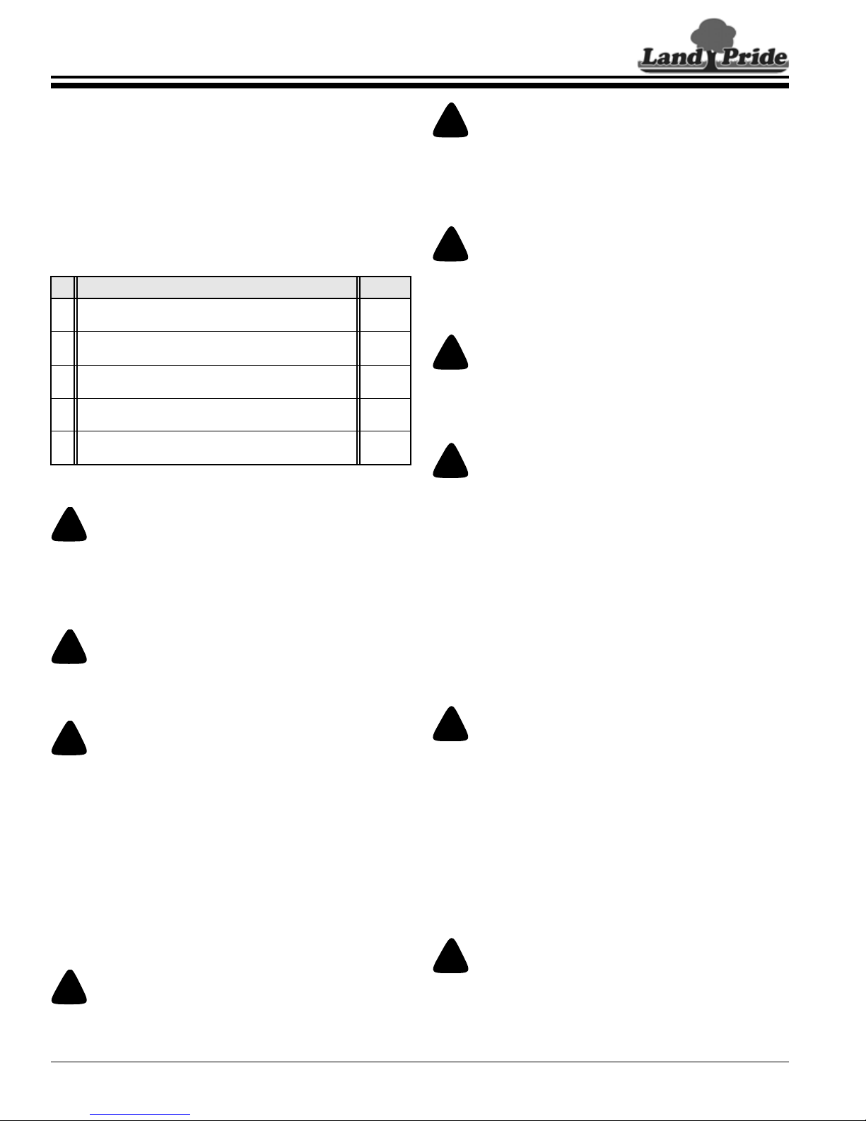
Table of Contents
!
DANGER
!
DANGER
!
DANGER
!
DANGER
!
WARNING
!
WARNING
!
WARNING
!
WARNING
!
WARNING
!
CAUTION
Section 2: Operating Procedures
Section 2: Operating Procedures
Operator’s Responsibilities
Hazard control and accident prevention are dependent
upon the awareness, concern, prudence, and proper
training involved in the operation, transport, storage, and
maintenance of the Snow Pusher. Therefore, it is
absolutely essential that no one operates this attachment
without first having read, fully understood, and become
totally familiar with the Operator’s Manual. Make sure the
operator has completed the Operating Checklist below.
Operating Checklist
Read and follow all safety rules carefully.
Refer to “Important Safety Information”.
Read and follow hook-up instructions.
Refer to “Hook-Up" instructions.
Read and follow all safety & operating instructions.
Refer to “Section 2: Operating Procedures”.
Read and follow all maintenance instructions.
Refer to “Section 3: Maintenance”.
Check unit initially and periodically for loose bolts.
Refer to “Torque Values Chart”.
Check Page
1
9 & 10
12
14
20
The Snow Pusher is back heavy and can tip over backwards
easily once unhooked. Always unhook unit on level ground
with support blocks under the skid shoes at the back to tip the
unit forward. Never unhook unit with back of unit facing
downhill.
Avoid hitting solid objects with this attachment as it does not
have a trip mechanism. Solid objects can damage equipment
and throw operator forwar d causing loss of control and injury .
Always wear the seat belt when operating this attachment.
Check hitch hook-up points frequently to make sure the
attachment is properly hooked-up to the loader hitch. An
improper fit-up can result in the attachment detaching from
the tractor causing a serious injury or death.
Safety Information
Allow only persons to operate this attachment who have fully
read and comprehended this manual and who have been
properly trained in the safe operation of this attachment.
Serious injury or death can result from the inability to read,
understand, and follow instructions provided in this manual.
Operate only on tractors equipped with a Roll-Over
Protective Structur e and seat belt. Fasten seat belt snugly and
securely to help protect against serious injury or death.
Do not get pinned between loader arms and tractor frame.
Loader arms and attachment can crush causing serious injury
or death to the operator and/or anyone nearby.
• Always operate attachment seated on the tractor with seat
belt fastened around operator.
• Keep your head, arms, and legs away from the loader lift arms
while seated on the tractor.
• Do not allow bystanders to be near the attachment, loader
arms, and tractor while operating the tractor.
• Before leaving the operator’s seat, lower attachment to the
ground, place gear selector in park or set park brake, turn off
engine, and remove switch key.
To avoid serious injury or death:
• Do not allow anyone to operate this attachment who has not
been properly trained in its safe operation or anyone who is
under the age of 16.
• Never carry riders on the tractor or attachment. Riders can be
struck by foreign objects, pinched by moving components,
thrown by sudden shifts in movement, entangled in rotating
components, can fall from equipment, or can obstruct the
operator’s view causing serious injury or death.
• Use steps, grab-handles, and skid-resistant surfaces when
getting on or off the tractor. Using unapproved surfaces and
handles to mount and dismount can result in a falling hazard
and cause serious injury or death.
To avoid serious injury or death, use Snow Pusher for its
intended purpose only.
• Use Snow Pusher to move snow and loose materials only.
Never use Snow Pusher to cut into soil, r ock, or other
compacted surfaces and never use it to push, pull, lift, tow , or
carry solid objects such as fence posts, stumps, rocks, etc.
• Never use Snow Pusher as a working platform or as a means
to raise and lower personnel.
• Doing any of the above could result in loss of tractor control,
tractor rollover, equipment damage, falling hazard, and/or
crushing hazard.
Keep away from electrical power lines. Place an orange
warning sign under overhead power lines indicating type of
danger above. Electrocution is often fatal.
SPL0548 & SPL0560 Snow Pusher 303-454M
12
Read and obey all instructions on the safety labels. Make sure
they are installed in their proper location and are in good
condition before operating the attachment.
9/07/16
Page 17

Section 2: Operating Procedures
!
WARNING
!
WARNING
Operating Tip: Operate Snow Pusher with skid
shoes making full contact with the ground from front
to back. Don’t apply a lot of down pressure on the
skid shoes. If available, operate with loader arms in
float.
Table of Contents
Transporting
When traveling on public roads, use accessory lights, SMV
sign, clean reflectors, and other adequate devices to warn
operators in other vehicles of your presence. Always comply
with all federal, state, and local laws.
Reduce ground speed when turning and leave enough
clearance to avoid making contact with obstacles such as
buildings, trees, fences, etc. Making contact can result in
equipment damage and cause serious injury or death.
1. Select a safe ground speed when transporting from
one area to another.
2. Transport with Snow Pusher low to the ground to
maintain stability of the tractor.
3. Reduce tractor ground speed when turning, and
leave enough clearance so the Snow Pusher does
not contact obstacles such as buildings, trees,
fences, etc.
4. Keep away from electrical power lines. Place an
orange warning sign under overhead power lines
indicating type of danger above.
5. When traveling on roadways, transport in such a way
that faster moving vehicles may pass you safely.
6. When traveling over rough or hilly terrain, shift tractor
to a lower gear.
General Operating Instructions
Once you have familiarized yourself with the Operator’s
Manual, completed the operating checklist, and properly
attached your Land Pride Snow Pusher to your tractor
loader, you are about ready to begin work. The Snow
Pusher is ideal for pushing snow off of driveways and
small parking lots or any other areas you want cleared of
snow. They also can be used to help clear soft materials
from areas such as feed lots, grain floors, etc.
Hopefully, you have checked out your work site for any
obstructions that you do not want to damage or to
encounter. Remove or flag any obstructions before
beginning your work.
The Snow Pusher’s primary purpose is to move snow or
other loose materials and pile it up. This function is best
done at an approximate 2 to 4 MPH ground speed.
Simply lower the Snow Pusher until it is resting on the
skid shoes and proceed forward. The blade should
immediately begin collecting snow or other loose
materials between the side panels and clearing an area
in front of you. You can transfer this material by pushing it
forward to a nearby location and then raising the Snow
Pusher to deposit your load. As the discharge pile builds,
you will want to tilt the top to the hitch back to push the
product up and onto the pile.
If using the pull back option, extend the loader hitch tilt
cylinders until the bottom edge of the pull back frame is
parallel with the paved surface. Lower the Snow Pusher
to carry the pull back blade slightly above the snow.
Slowly approach the snow close to a wall or garage door
making sure you stop before getting too close. Lower pull
back until its blade and frame are resting on the paved
surface. Making sure no one is behind you, start backing
up to pull snow away. Keep backing up until you have
pulled the snow far enough that you can now remove the
pile by pushing the pile forward with the Snow Pusher.
Achieving the desired effect will require a little
experimentation and experience for your given condition.
With a little practice, you should become a very good
operator consistently achieving the desired results you
expect with your Land Pride Snow Pusher.
See “Specifications & Capacities” on page 18 and
“Features & Benefits” on page 19 for additional
information and performance enhancing options.
9/07/16
SPL0548 & SPL0560 Snow Pusher 303-454M
13
Page 18
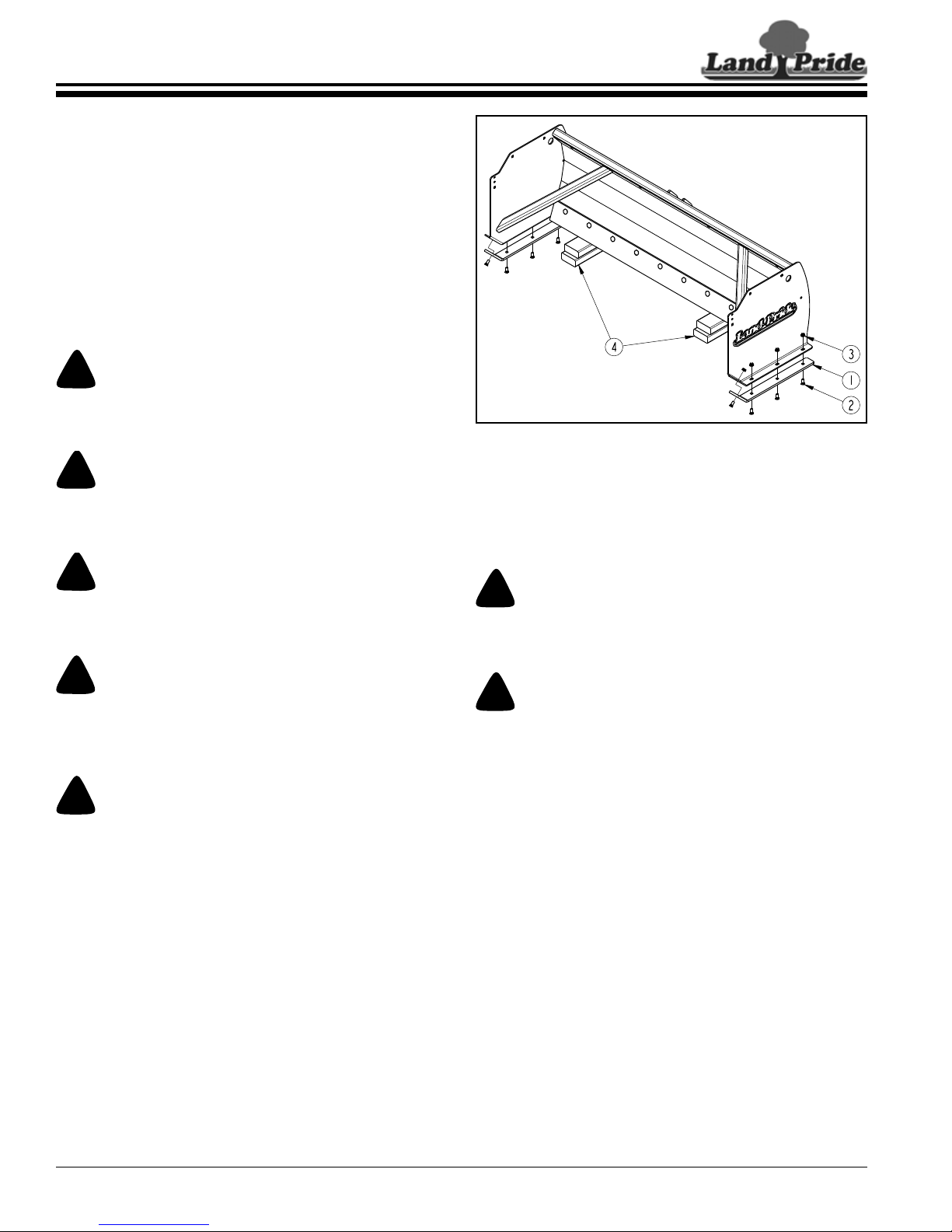
Table of Contents
!
DANGER
!
DANGER
!
DANGER
!
WARNING
!
CAUTION
!
WARNING
!
WARNING
39719
Section 3: Maintenance
Section 3: Maintenance
Maintenance
Proper servicing and adjustment are key to the long life of
any attachment. With careful inspection and routine
maintenance, you can avoid costly downtime and repair.
Check all bolts after using the unit for several hours to be
sure they are tight. Replace any worn, damaged, or
illegible safety labels by obtaining new labels from your
nearest Land Pride dealer.
The parts on your Snow Pusher have been specially
designed and should only be replaced with genuine Land
Pride parts. Do not alter the Snow Pusher in a way which
will adversely affect its performance.
Do not allow anyone to perform maintenance on this
attachment who has not been properly trained in its safe
operation.
Skid Shoe Replacement
Figure 3-1
Do not work underneath raised lift arms unless an approved
lift-arm support is available and is used to secure the lift arms
in the raised position.
To avoid serious injury or death, always secure underside of
attachment with solid supports before working under it. Never
use concrete blocks as a support.
Do not alter Land Pride equipment or replace parts with other
brands. Doing so can cause equipment to perform improperly
and may lead to breakage causing bodily injury or death.
Replace parts only with genuine Land Pride parts.
Perform scheduled maintenance. Not maintaining the Snow
Pusher in a timely manner can damage the unit and make it
dangerous to operate.
Skid Shoes
Refer to Figure 3-1:
The skid shoes are 3/8" thick when new and should be
replaced before they are worn through.
Perform maintenance to the Snow Pusher with unit hooked to
the loader arms. An unhooked Snow Pusher can tip over
backwards causing serious injury or death.
To avoid serious injury or death, always secure underside of
attachment with solid supports before working under it. Never
use concrete blocks as a support.
1. Park tractor with attached Snow Pusher on level
ground.
2. Lower Snow Pusher until blade is resting
4" to 6" off the ground on support blocks (#4).
3. Shut tractor down properly before dismounting to
adjust skid shoes. Refer to “Tractor Shutdown
Procedures” on page 6.
4. On the left-hand side, remove hex whiz nuts (#3),
plow bolts (#2), and skid shoe (#1).
5. Repeat step 4 for the right-hand side.
6. Reattach new skid shoes to the left and right-hand
sides with existing 3/8"-16 x 1" GR5 plow bolts (#2)
and hex whiz nuts (#3). Tighten hex whiz nuts to the
correct torque.
SPL0548 & SPL0560 Snow Pusher 303-454M
14
9/07/16
Page 19
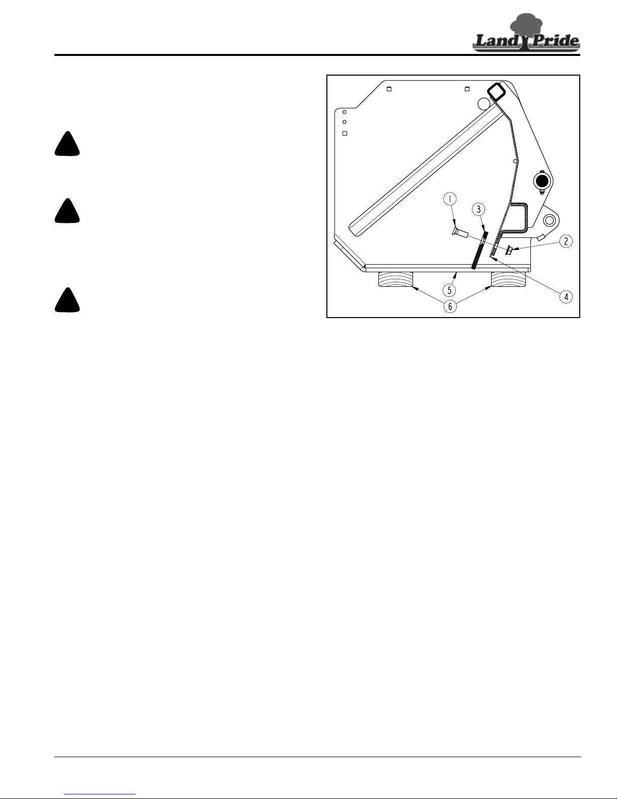
Table of Contents
!
WARNING
!
WARNING
!
CAUTION
39721
Section 3: Maintenance
Steel Blade (Optional)
Refer to Figure 3-2:
Replace steel blade (#3) before its cutting edge is worn
even with bottom of moldboard (#4).
Replace steel blade with Snow Pusher attached to a tractor
loader. An unhooked Snow Pusher can tip over backwards
causing serious injury or death.
Always secure attachment with solid supports befor e working
under it. Never work under attachment supported by
hydraulics. Hydraulics can drop attachment if controls are
actuated or if hydraulic lines burst. Either situation can drop
attachment instantly even when power to hydraulics is off.
Exercise caution when working near or on the steel blade. The
cutting edge can be sharp. Always wear gloves when working
around the steel blade.
1. Park tractor and Snow Pusher on level ground. Lower
Snow Pusher until skid shoes (#5) are resting on
support blocks (#6) as shown. (Support blocks
should not be located under the steel blade.)
2. Shut tractor down properly before dismounting. Refer
to “Tractor Shutdown Procedures” on page 6.
1. Remove hex whiz nuts (#2), plow bolts (#1), and
steel blade (#3).
2. Attach new steel blade (#3) as shown with
1/2"-13 x 1 1/2" GR5 plow bolts (#1) and hex whiz
nuts (#2).
3. Center blade (#3) between the side panels and
tighten hex whiz nuts (#2) to the correct torque.
Steel Blade Replacement
Figure 3-2
9/07/16
SPL0548 & SPL0560 Snow Pusher 303-454M
15
Page 20
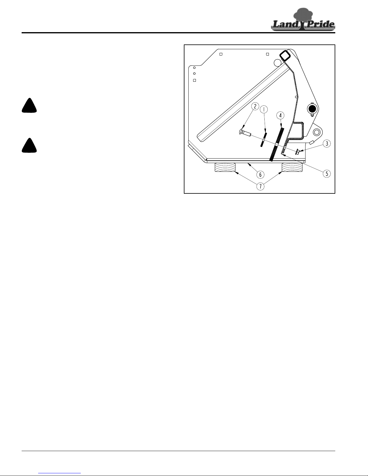
Table of Contents
!
WARNING
!
WARNING
39720
Section 3: Maintenance
Poly Blade (Optional)
Refer to Figure 3-3:
The optional poly blade (#4) can be reversed to extend its
life. Reverse poly blade before its cutting edge is worn
even with bottom of moldboard (#5). Replace poly blade
before both cutting edges have worn even with bottom of
moldboard (#5).
Reverse or replace poly blade with Snow Pusher attached to a
tractor loader. An unhooked Snow Pusher can tip over
backwards causing serious injury or death.
Always secure attachment with solid supports befor e working
under it. Never work under attachment supported by
hydraulics. Hydraulics can drop attachment if controls are
actuated or if hydraulic lines burst. Either situation can drop
attachment instantly even when power to hydraulics is off.
Preparation
1. Park tractor and Snow Pusher on level ground. Lower
Snow Pusher until skid shoes (#6) are resting on
support blocks (#7) as shown. (Support blocks
should not be located under poly blade (#4).)
2. Shut tractor down properly before dismounting to
reverse or replace blade. Refer to “Tractor
Shutdown Procedures” on page 6.
Reverse Poly Blade
The poly blade (#4) can be reversed (rotated upside
down) and reused to extend its life.
1. C o m p l e t e “Preparation” on this page before
completing steps below.
2. Remove hex whiz nuts (#3), carriage bolts (#2),
blade support bars (#1), and poly blade (#4).
3. Rotate poly blade upside down and reattach it with
existing blade support bar (#1) and existing
hardware (#2 & #3). Do not tighten nuts at this time.
4. Center poly blade between side panels and tighten
hex whiz nuts (#3) to the correct torque.
5. Back drag unit 50 yards on dry concrete to level
trailing edge of snow blade with bottom of skid shoe.
Poly Blade Rotating & Replacement
Figure 3-3
Replace Poly Blade
Replace poly blade when both edges are worn close to
bottom of moldboard (#5).
1. C o m p l e t e “Preparation” on this page before
completing steps below.
2. Remove hex whiz nuts (#3), carriage bolts (#2),
blade support bars (#1), and poly blade (#4).
3. Reattach new poly blade (#4) with existing blade
support bar (#1) and existing hardware (#2 & #3). Do
not tighten nuts at this time.
4. Center poly blade between side panels and tighten
hex whiz nuts (#3) to the correct torque.
5. Back drag unit 50 yards on dry concrete to level
trailing edge of snow blade with bottom of skid shoe.
SPL0548 & SPL0560 Snow Pusher 303-454M
16
9/07/16
Page 21

Table of Contents
Land Pride Aerosol Touch-up Paint
Part No. Part Description
821-002C PAINT LP BLACK AEROSOL SPRAY CAN
821-066C PAINT ORANGE SPRAY CAN
Section 3: Maintenance
Long-Term Storage
Clean, inspect, service, and make necessary repairs to
the Snow Pusher when parking it for long periods and
when parking it at the end of a working season. This will
help ensure that the Snow Pusher is ready for field use
next time you hook-up to it.
1. Clean off any dirt that may have accumulated on the
Snow Pusher. Scrape off compacted dirt and then
wash surfaces thoroughly with a garden hose.
2. Inspect Snow Pusher for loose, damaged, or worn
parts. Adjust and tighten loose parts. When needed,
replace parts with genuine Land Pride Parts only.
3. Repaint parts where paint is worn or scratched to
prevent rust. Ask your dealer for Land Pride aerosol
touch-up paint. Paint is also available in touch-up
bottles with brush, quarts, and gallon sizes by adding
TU, QT, or GL to the end of the aerosol part number.
4. A light coating of oil or grease may be applied to the
lower wear areas in lieu of paint to minimize
oxidation.
5. Replace all damaged or missing decals.
6. Store Snow Pusher on a level surface in a clean, dry
place. Inside storage will reduce maintenance and
make for a longer Snow Pusher life.
7. Lower Snow Pusher until skid shoes are resting on
support blocks at the back and on the ground at the
front to make the unit tip forward. For detailed
instructions, refer to “Unhook With BX Quick Hitch”
on page 9 or “Unhook Without BX Quick Hitch” on
page 11.
9/07/16
SPL0548 & SPL0560 Snow Pusher 303-454M
17
Page 22
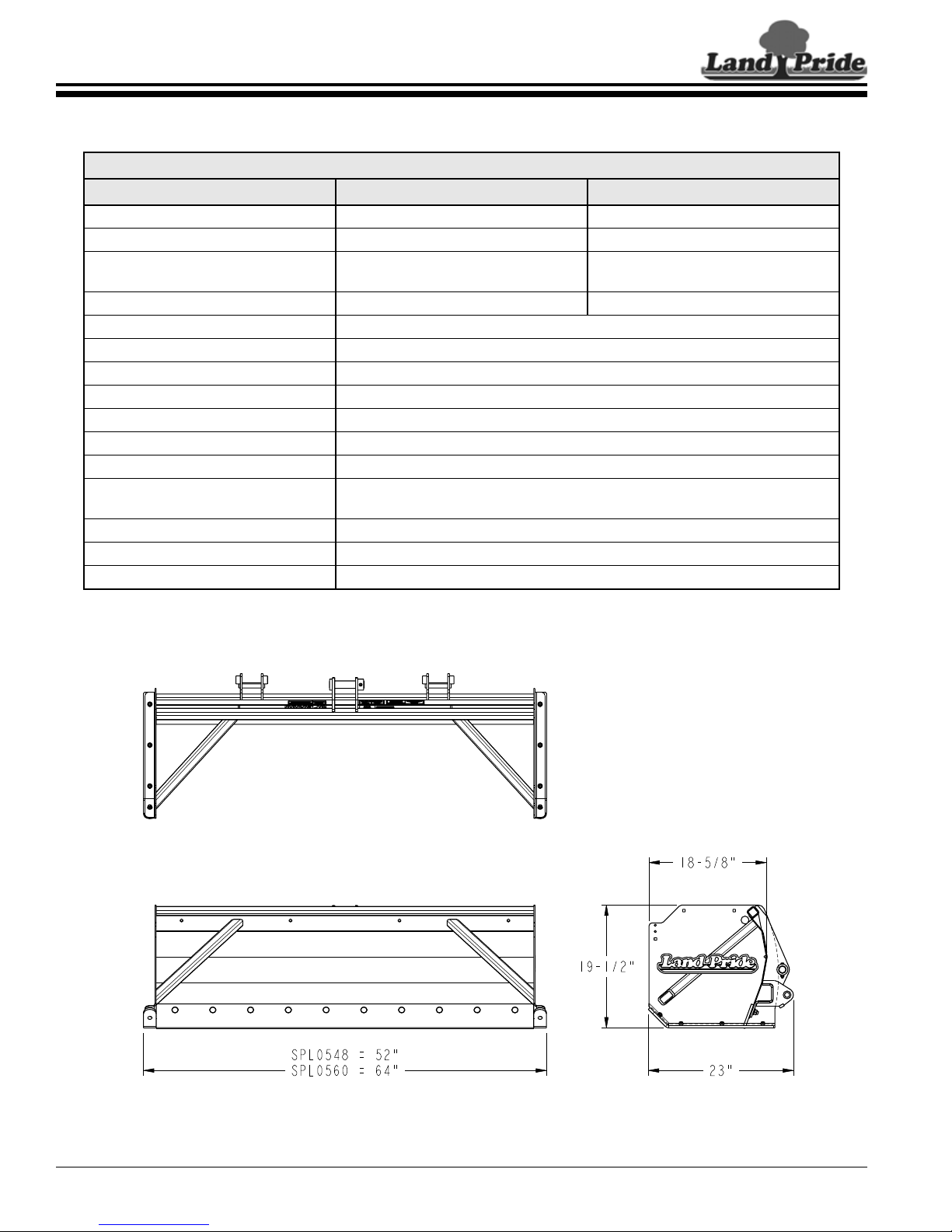
Table of Contents
Section 4: Specifications & Capacities
Section 4: Specifications & Capacities
SPL05 Series
Specifications & Capacities
Model Numbers SPL0548 SPL0560
Working width 48" 60"
Capacity (approximate) 9 ft
Weight with poly blade
with steel blade
Weight of pull back option 51 lbs 62 lbs
Horsepower range Maximum 28 hp
Operating weight of carrier 1,800 lbs.
Lift capacity of carrier 800 lbs. at pivot pins
Hitch type Fits Kubota BX front loader hitch, with or without Kubota BX6315 Quick Hitch.
Skid shoes 3/8" x 2" Replaceable
Moldboard thickness 12 Ga.
Side panel thickness 3/16"
Poly blades (option)
Steel blades (option) 3/8" x 4" Replaceable blade(s)
Pull Back (option) 3/8" x 3" Steel blade
Orange marker (accessory) 28" Tall, bolts to the side panels
3
160 lbs
168 lbs
1/2" x 6" Poly
Reversible and replaceable blade
3
12 ft
182 lbs
190 lbs
SPL0548 & SPL0560 Snow Pusher 303-454M
18
39722
9/07/16
Page 23

Table of Contents
Section 5: Features & Benefits
Section 5: Features & Benefits
SPL05 Series
Features Benefits
Designed to fit Kubota’s BX tractors
with front loaders
3/16" Side panels Built heavy to handle the tough jobs for Kubota BX tractors.
Bracing on side panels and back Reinforces side panels and back for a stronger unit.
1/4" Formed back plate at blade mount Makes for a strong moldboard.
Replaceable skid shoes Protects the side panels from wear.
Reversible poly blade The blade can be reversed to extend the life of the blade.
Replaceable poly or steel blades The blades can be replaced to extend the life of the Snow Pusher.
Pull back with 3/8" weld-on steel blade Used to pull snow away from structures such as garage doors and other objects.
28" High orange marker (accessory)
Easy to attach to Kubota’s BX tractor loaders with or without Kubota BX6315
Quick Hitch. A good fit for Kubota BX tractors with front loaders.
Options & Accessories
Assist in locating outer ends of the Snow Pusher when approaching buildings,
trees, poles, and other obstacles that can damage equipment.
9/07/16
SPL0548 & SPL0560 Snow Pusher 303-454M
19
Page 24
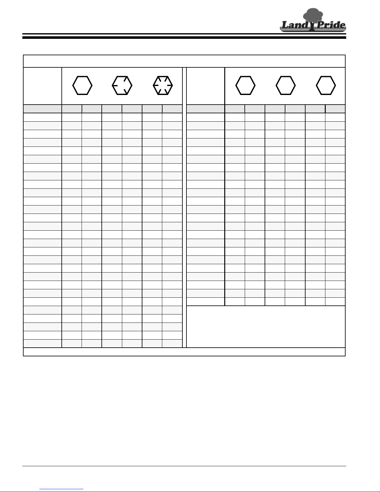
Section 6: Torque Values Chart
5.8
8.8
10.9
Section 6: Torque Values Chart
Torque Values Chart for Common Bolt Sizes
Bolt Head Identification Bolt Head Identification
Table of Contents
Bolt Size
(inches) Grade 2 Grade 5 Grade 8
1
in-tpi
1/4" - 20 7. 4 5 . 6 11 8 1 6 1 2 M 5 X 0.8 436597
1/4" - 28 8.5 6 13 10 18 14 M 6 X 1 7 5 11 8 15 11
5/16" - 18 15 11 24 17 33 25 M 8 X 1.25 17 12 26 19 36 27
5/16" - 24 17 13 26 19 37 27 M 8 X 1 18 13 28 21 39 29
3/8" - 16 27 20 42 31 59 44 M10 X 1.5 33 24 52 39 72 53
3/8" - 24 31 22 47 35 67 49 M10 X 0.75 39 29 61 45 85 62
7/16" - 14 43 32 67 49 95 70 M12 X 1.75 58 42 91 67 125 93
7/16" - 20 49 36 75 55 105 78 M12 X 1.5 60 44 95 70 130 97
1/2" - 13 66 49 105 76 145 105 M12 X 1 90 66 105 77 145 105
1/2" - 20 75 55 11 5 85 165 120 M14 X 2 92 68 145 105 200 150
9/16" - 12 95 70 150 110 210 155 M14 X 1.5 99 73 155 115 l215 160
9/16" - 18 105 79 165 120 235 170 M16 X 2 145 105 225 165 315 230
5/8" - 11 130 97 205 150 285 210 M16 X 1.5 155 115 240 180 335 245
5/8" - 18 150 110 230 170 325 240 M18 X 2.5 195 145 310 230 405 300
3/4" - 10 235 170 360 265 510 375 M18 X 1.5 220 165 350 260 485 355
3/4" - 16 260 190 405 295 570 420 M20 X 2.5 280 205 440 325 610 450
7/8" - 9 225 165 585 430 820 605 M20 X 1.5 310 230 650 480 900 665
7/8" - 14 250 185 640 475 905 670 M24 X 3 480 355 760 560 1050 780
1" - 8 340 250 875 645 1230 910 M24 X 2 525 390 830 610 1150 845
1" - 12 370 275 955 705 1350 995 M30 X 3.5 960 705 1510 112 0 2100 1550
1-1/8" - 7 480 355 1080 795 1750 1290 M30 X 2 1060 785 1680 1240 2320 1710
1-1/8" - 12 540 395 1210 890 1960 1440 M36 X 3.5 1730 1270 2650 1950 3660 2700
1-1/4" - 7 680 500 1520 1120 2460 1820 M36 X 2 1880 1380 2960 2190 4100 3220
1-1/4" - 12 750 555 1680 1240 2730 2010
1-3/8" - 6 890 655 1990 1470 3230 2380
1-3/8" - 12 1010 745 2270 1670 3680 2710
1-1/2" - 6 1180 870 2640 1950 4290 3160
1-1/2" - 12 1330 980 2970 2190 4820 3560
Torque tolerance + 0%, -15% of torquing values. Unless otherwise specified use torque values listed above.
N · m 2ft-lb 3N · m ft-lb N · m ft-lb mm x pitch 4N · m ft-lb N · m ft-lb N · m ft-lb
Bolt Size
(Metric) Class 5.8 Class 8.8 Class 10.9
1
in-tpi = nominal thread diameter in inches-threads per inch
2
N· m = newton-meters
3
ft-lb= foot pounds
4
mm x pitch = nominal thread diameter in millimeters x thread
pitch
SPL0548 & SPL0560 Snow Pusher 303-454M
20
9/07/16
Page 25

Section 7: Warranty
Section 7: Warranty
Table of Contents
Warranty
Land Pride warrants to the original purchaser that this Land Pride product will
be free from defects in material and workmanship beginning on the date of
purchase by the end user according to the following schedule when used as
intended and under normal service and conditions for personal use.
Overall Unit: One year Parts and Labor
Blades and Skid Shoes: Considered wear items.
This Warranty is limited to the repair or replacement of any defective part by
Land Pride and the installation by the dealer of any such replacement part, and
does not cover common wear items such as blades, belts, tines, etc. Land Pride
reserves the right to inspect any equipment or parts which are claimed to have
been defective in material or workmanship.
This Warranty does not apply to any part or product which in Land Pride’s
judgment shall have been misused or damaged by accident or lack of normal
maintenance or care, or which has been repaired or altered in a way which
adversely affects its performance or reliability, or which has been used for a
purpose for which the product is not designed. Misuse also specifically includes
failure to properly maintain oil levels, grease points, and driveline shafts.
Claims under this Warranty must be made to the dealer which originally sold
the product and all warranty adjustments must be made through such dealer. Land
Pride reserves the right to make changes in materials or design of the product at
any time without notice.
This Warranty shall not be interpreted to render Land Pride liable for damages
of any kind, direct, consequential, or contingent to property. Furthermore, Land
Pride shall not be liable for damages resulting from any cause beyond its
reasonable control. This Warranty does not extend to loss of crops, any expense
or loss for labor, supplies, rental machinery or for any other reason.
No other warranty of any kind whatsoever, express or implied, is made
with respect to this sale; and all implied warranties of merchantability and
fitness for a particular purpose which exceed the obligations set forth in this
written warranty are hereby disclaimed and excluded from this sale.
This Warranty is not valid unless registered with Land Pride within 30 days from
the date of purchase.
IMPORTANT: The Online Warranty Registration should be completed by the dealer at the time of
purchase. This information is necessary to provide you with quality customer service.
Model Number ____________________ Serial Number ____________________
9/07/16
SPL0548 & SPL0560 Snow Pusher 303-454M
21
Page 26

Corporate Office: P.O. Box 5060
Salina, Kansas 67402-5060 USA
www.landpride.com
 Loading...