

Page 1
Table of Contents
Rotary Tillers
RTR12 & RTA12 Series (Serial No. 884764-)
RTR1242, RTR1250, RTR1258, RTR1266, & RTR1274
RTA1242, RTA1250, RTA1258, RTA1266, & RTA1274
30361A
RTA12 Series Rotary Tillers
RTR12 Series Rotary Tillers
Operator’s Manual
Read the Operator’sManual entirely.When you
see this symbol, the subsequent instructions and
warnings are serious - follow without exception.
!
Your life and the lives of others depend on it!
Coverphoto may show optional equipment
not supplied with standard unit.
© Copyright 2014 Printed
30345A
311-785M
8/12/14
Page 2

Table of Contents
Table of Contents
Important Safety Information . . . . . . . . . . . . . 1
Safety at All Times . . . . . . . . . . . . . . . . . . . . . . . . 1
Look For The Safety Alert Symbol . . . . . . . . . . . . . 1
Safety Labels . . . . . . . . . . . . . . . . . . . . . . . . . . . . . 4
Introduction . . . . . . . . . . . . . . . . . . . . . . . . . . . 8
Application . . . . . . . . . . . . . . . . . . . . . . . . . . . . . . . 8
Using This Manual . . . . . . . . . . . . . . . . . . . . . . . . . 8
Terminology . . . . . . . . . . . . . . . . . . . . . . . . . . . . . 8
Definitions . . . . . . . . . . . . . . . . . . . . . . . . . . . . . . 8
Owner Assistance . . . . . . . . . . . . . . . . . . . . . . . . . . 8
Serial Number . . . . . . . . . . . . . . . . . . . . . . . . . . . 8
Further Assistance . . . . . . . . . . . . . . . . . . . . . . . . 8
Section 1: Assembly and Set-Up . . . . . . . . . . 9
Dealer Preparations . . . . . . . . . . . . . . . . . . . . . . . . 9
Tractor Requirements . . . . . . . . . . . . . . . . . . . . . . . 9
Torque Requirements . . . . . . . . . . . . . . . . . . . . . . . 9
RTR & RTA Parking Stand Installation . . . . . . . . . . 9
RTR & RTA Rear Chain Installation . . . . . . . . . . . . 9
Reverse Rotation (RTR) Rotary Tillers . . . . . . . . . 10
RTR Front Deflector Assembly . . . . . . . . . . . . . 10
RTR 3-Point Hitch Assembly . . . . . . . . . . . . . . . 11
Standard Rotation (RTA) Rotary Tillers . . . . . . . . . 12
RTA 3-Point Hitch Assembly . . . . . . . . . . . . . . . 12
Tractor Hook-Up . . . . . . . . . . . . . . . . . . . . . . . . . . 13
Driveline Installation . . . . . . . . . . . . . . . . . . . . . . . 13
Check Driveline Collapsible Length . . . . . . . . . . 14
Shorten Driveline . . . . . . . . . . . . . . . . . . . . . . . . 15
Check Driveline Maximum Length . . . . . . . . . . . 15
Check Driveline Interference . . . . . . . . . . . . . . . 15
Section 2: Operating . . . . . . . . . . . . . . . . . . . 16
Operating Checklist . . . . . . . . . . . . . . . . . . . . . . . . 16
Inspections . . . . . . . . . . . . . . . . . . . . . . . . . . . . . . 16
Safety Information . . . . . . . . . . . . . . . . . . . . . . . . . 16
Transporting . . . . . . . . . . . . . . . . . . . . . . . . . . . . . 18
Parking . . . . . . . . . . . . . . . . . . . . . . . . . . . . . . . . . 18
General Operating Notes . . . . . . . . . . . . . . . . . . . 19
General Operating Instructions . . . . . . . . . . . . . . . 19
Section 3: Adjustments . . . . . . . . . . . . . . . . . 20
RTA & RTR12 Tiller Hitch Offset . . . . . . . . . . . . . . 20
Drive Chain Tension . . . . . . . . . . . . . . . . . . . . . . . 20
RTR12 Series Tillers . . . . . . . . . . . . . . . . . . . . . 20
RTA12 Series Tillers . . . . . . . . . . . . . . . . . . . . . 20
Rear Deflector . . . . . . . . . . . . . . . . . . . . . . . . . . . . 21
Skid Shoe Adjustment . . . . . . . . . . . . . . . . . . . . . . 21
Section 4: Maintenance and Lubrication . . . 22
Maintenance . . . . . . . . . . . . . . . . . . . . . . . . . . . . . 22
Tine Replacement . . . . . . . . . . . . . . . . . . . . . . . . . 22
Driveline Protection . . . . . . . . . . . . . . . . . . . . . . . . 22
Clutch Run-In . . . . . . . . . . . . . . . . . . . . . . . . . . . 22
Clutch Disassembly . . . . . . . . . . . . . . . . . . . . . . 23
Clutch Assembly . . . . . . . . . . . . . . . . . . . . . . . . 23
Storage . . . . . . . . . . . . . . . . . . . . . . . . . . . . . . . . . 24
Ordering Replacement Parts . . . . . . . . . . . . . . . . . 24
Lubrication Points . . . . . . . . . . . . . . . . . . . . . . . . . 25
Driveline U-Joint . . . . . . . . . . . . . . . . . . . . . . . . . 25
Driveline Shield Bearings . . . . . . . . . . . . . . . . . . 25
Driveline Shaft . . . . . . . . . . . . . . . . . . . . . . . . . . 25
Bearing On Right End Of Rotor Shaft . . . . . . . . . 26
Chaincase . . . . . . . . . . . . . . . . . . . . . . . . . . . . . 26
Gearbox . . . . . . . . . . . . . . . . . . . . . . . . . . . . . . . 26
Section 5: Troubleshooting . . . . . . . . . . . . . . 27
Section 6: Specifications & Capacities . . . . . 28
Section 7: Features & Benefits . . . . . . . . . . . 30
Section 8: Torque Values Chart . . . . . . . . . . 32
Section 9: Warranty . . . . . . . . . . . . . . . . . . . . 33
© Copyright 2014 All rights Reserved
Land Pride provides this publication “as is” without warranty of any kind, either expressed or implied. While every precaution has been taken in the
preparationof this manual,Land Pride assumesno responsibility forerrors oromissions. Neitherisany liabilityassumed fordamages resulting fromthe use
oftheinformation contained herein. LandPridereservesthe right to reviseandimprove its productsas it sees fit. This publicationdescribes the state of this
product at the time of its publication, and may not reflect the product in the future.
Land Pride is a registered trademark.
All other brands and product names are trademarks or registered trademarks of their respective holders.
Printed in the United States of America.
RTR12 & RTA12 Series (Serial No. 884764-) Rotary Tillers 311-785M
8/12/14
Page 3
Land Pride
Table of Contents
Important Safety Information
Important Safety Information
These are common practices that may or may not be applicable to the products described in
this manual.
Safety at All Times
Thoroughly read and understand
the instructions given in this
manual before operation. Refer to
the “Safety Label” section, read all
instructions noted on them.
Do not allow anyone to operate
this equipment who has not fully
read and comprehended this
manual and who has not been
properly trained in the safe
operation of the equipment.
▲ Operator should be familiarwith all
functions of the unit.
▲ Operate implement from the
driver’s seat only.
▲ Make sure all guards and shields
are in place and secured before
operating implement.
▲ Do not leave tractor or implement
unattended with engine running.
▲ Dismounting from a moving tractor
could cause serious injury or
death.
▲ Do not allow anyone to stand
between tractor and implement
while backing up to implement.
▲ Keep hands, feet, and clothing
away from power-driven parts.
▲ Wear snug fitting clothing to avoid
entanglement with moving parts.
▲ Watch out for wires, trees, etc.,
when raising implement. Make
sure all persons are clear of
working area.
▲ Turningtractor too tight may cause
implement to ride up on wheels.
This could result in injury or
equipment damage.
▲ Do not carry passengers on
implement at any time.
Look For The Safety Alert Symbol
The SAFETY ALERT SYMBOL indicates there is a
potential hazard to personal safety involved and extra
safety precaution must be taken. When you see this
symbol, be alert and carefully read the message that
follows it. In addition to design and configuration of
!
Be Aware of
Signal Words
A Signal word designates a degree or
level of hazard seriousness. The
signal words are:
!
DANGER
Indicates an imminently hazardous
situation which, if not avoided, will
result in death or serious injury. This
signal word is limited to the most
extreme situations, typically for
machine components that, for
functional purposes, cannot be
guarded.
For Your Protection
▲ Thoroughly read and understand
the “Safety Label” section, read all
instructions noted on them.
equipment, hazard control, and accident prevention
are dependent upon the awareness, concern,
prudence, and proper training of personnel involved
in the operation, transport, maintenance, and storage
of equipment.
!
WARNING
Indicates a potentially hazardous
situation which, if not avoided, could
result in death or serious injury, and
includes hazards that are exposed
when guards are removed. It may also
be used to alert against unsafe
practices.
!
CAUTION
Indicates a potentially hazardous
situation which, if not avoided, may
result in minor or moderate injury. It
may also be used to alert against
unsafe practices.
Shutdown and Storage
▲ Lower machine to ground, put
tractor in park, turn off engine, and
remove the key.
▲ Detach and store implements in an
area where children normally do
not play. Secure implement by
using blocks and supports.
OFF
8/12/14
Parts Manual QR Locator
The QR (Quick Reference) code on the front
cover and to the left will take you to the
Parts Manual for this equipment. Download
the appropriate App on your camera phone,
open the App, point your phone on the QR
code and take a picture.
RTR12 & RTA12 Series (Serial No. 884764-) Rotary Tillers 311-785M
REMO
VE
Dealer QR Locator
The QR code on the left will
link you to available dealers
for Land Pride products.
Refer to Parts Manual
QR Locator on this page for
detailed instructions.
1
Page 4
Table of Contents
Important Safety Information
These are common practices that may or may not be applicable to the products described in
this manual.
Use Safety
Lights and Devices
▲ Slow moving tractors, self-
propelled equipment, and towed
implements can create a hazard
whendriven on publicroads.They
are difficult to see, especially at
night.
▲ Flashing warning lights and turn
signals are recommended
wheneverdriving on public roads.
Transport
Machinery Safely
▲ Comply with state and local laws.
▲ Maximum transport speed for
implement is 20 mph. DO NOT
EXCEED.Never travel at a speed
which does not allow adequate
control of steering and stopping.
Some rough terrain require a
slower speed.
▲ Sudden braking can cause a
towed load to swerve and upset.
Reduce speed if towed load is not
equipped with brakes.
▲ Use the following maximum
speed - tow load weight ratios as
a guideline:
20 mph when weight is less
than or equal to the weight of
tractor.
10 mph when weight is more
than weight of tractor but less
than double the weight of
tractor.
▲ IMPORTANT: Do not tow a load
that is more than double the
weight of tractor.
Practice Safe
Maintenance
▲ Understand procedure before
doing work. Use proper tools and
equipment, refer to Operator’s
Manual for additional information.
▲ Work in a clean dry area.
▲ Lower the implement to the
ground, put tractor in park, turn off
engine, and remove key before
performing maintenance.
▲ Allow implement to cool
completely.
▲ Do not grease or oil implement
while it is in operation.
▲ Inspect all parts. Make sure parts
are in good condition & installed
properly.
▲ Remove buildup of grease, oil or
debris.
▲ Remove all tools and unused
parts from implement before
operation.
Operate Equipment Safely
▲ The operator must not use drugs
or alcohol as they can change the
alertness or coordination of that
person while operating the
equipment. The operator should, if
he is taking over-the-counter
drugs, seek medical advice on
whether he can safely operate the
equipment.
▲ Keep bystanders away.
Start tractor with gearshift in park
or neutral and park brakes set. Be
aware hydraulics are live upon
start-up and can move instantly.
▲ Dig Safe, Call 811.
Always contact your local utility
companies (electrical, telephone,
gas, water, sewer, and others)
before digging so that they may
mark the location of any under
ground services in the area. Be
sure to ask how close you can
work to the marks they positioned.
▲ Avoid contact with any over head
utility lines or electrically charged
conductors.
RTR12 & RTA12 Series (Serial No. 884764-) Rotary Tillers 311-785M
2
8/12/14
Page 5
Land Pride
Table of Contents
Important Safety Information
These are common practices that may or may not be applicable to the products described in
this manual.
Prepare for Emergencies
▲ Be prepared if a fire starts.
▲ Keep a first aid kit and fire
extinguisher handy.
▲ Keep emergency numbers for
doctor, ambulance, hospital, and
fire department near phone.
911
Wear
Protective Equipment
▲ Wear protective clothing and
equipment appropriate for the job.
Avoid loose fitting clothing.
▲ Prolonged exposure to loud noise
can cause hearing impairment or
hearing loss. Wear suitable
hearing protection such as
earmuffs or earplugs.
▲ Operating equipment safely
requires the full attention of the
operator. Avoid wearing radio
headphones while operating
machinery.
Avoid High
Pressure Fluids Hazard
▲ Escaping fluidunder pressure can
penetrate the skin causing
serious injury.
▲ Avoid the hazard by relieving
pressure before disconnecting
hydrauliclines or performing work
on the system.
▲ Make sure all hydraulic fluid
connections are tight and all
hydraulic hoses and lines are in
good condition before applying
pressure to the system.
▲ Use a piece of paper or
cardboard, NOT BODY PARTS, to
check for suspected leaks.
▲ Wear protective gloves and safety
glasses or goggles when working
with hydraulic systems.
▲ DO NOT DELAY. If an accident
occurs, see a doctor familiar with
this type of injury immediately.
Any fluid injected into the skin or
eyes must be treated
within a fewhours or
gangrene may
result.
Keep Riders
Off Machinery
▲ Riders obstruct the operator’s
view, they could be struck by
foreign objects or thrown from the
machine.
▲ Never allow children to operate
equipment.
Tire Safety
▲ Tire changing can be dangerous
and should be preformed by
trained personnel using the
correct tools and equipment.
▲ When inflating tires, use a clip-on
chuck and extension hose long
enough to allow you to stand to
one side and NOT in front of or
over the tire assembly. Use a
safety cage if available.
▲ When removing and installing
wheels, use wheel handling
equipment adequate for the
weight involved.
Handle
Chemicals Properly
▲ Protective clothing should be
worn.
▲ Handle all chemicals with care.
▲ Follow instructions on container
label.
▲ Agricultural chemicals can be
dangerous. Improper use can
seriously injure persons, animals,
plants, soil, and property.
▲ Inhaling smoke from any type of
chemical fire is a serious health
hazard.
▲ Store or dispose of unused
chemicals as specified by the
chemical manufacturer.
8/12/14
RTR12 & RTA12 Series (Serial No. 884764-) Rotary Tillers 311-785M
3
Page 6

Important Safety Information
Table of Contents
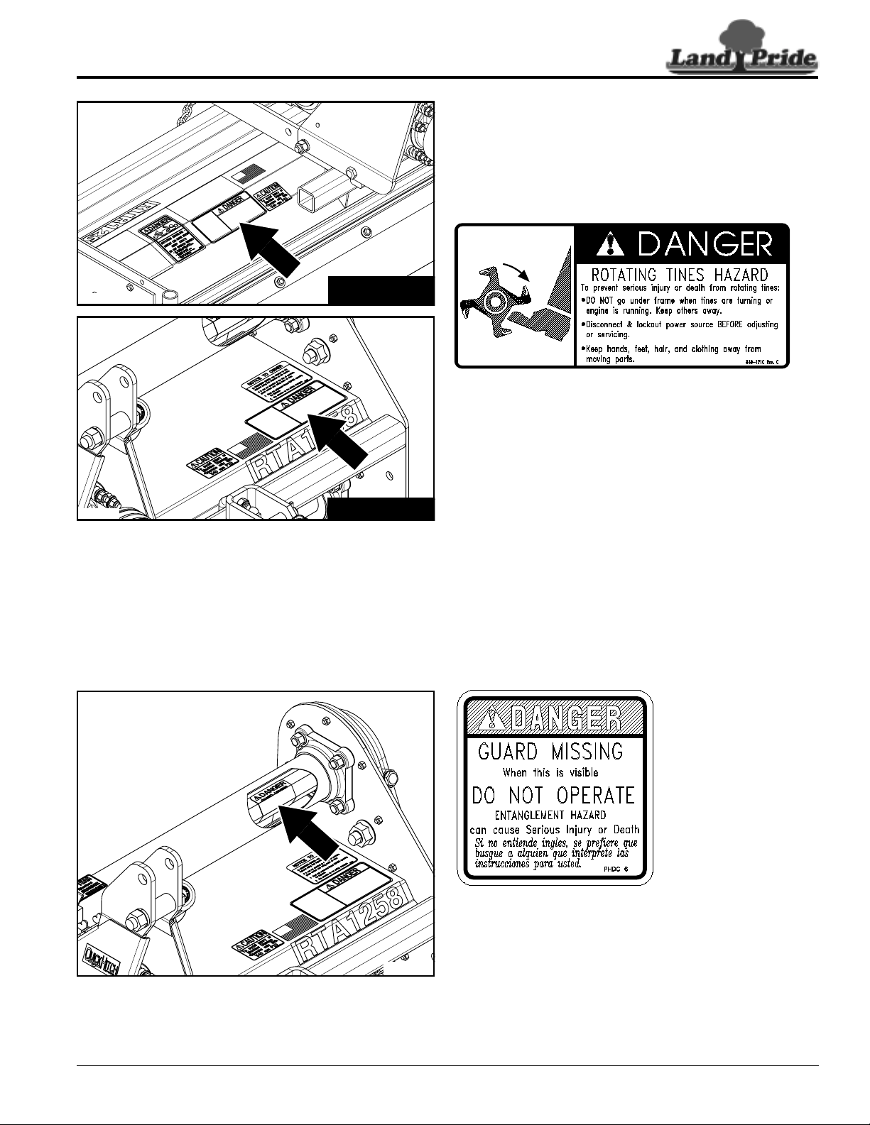
Safety Labels
Your Rotary Tiller comes equipped with all safety labels in
place. They were designed to help you safely operate your
implement. Read and follow their directions.
1. Keep all safety labels clean and legible.
2. Refer to this section for proper label placement. Replace
all damaged or missing labels. Order new labels from your
nearest Land Pride dealer. To find your nearest dealer,
visit our dealer locator at www.landpride.com.
3. Some new equipment installed during repair requires
safety labels to be affixed to the replaced component as
30346A
RTR12 Series
specified by Land Pride. When ordering new components
make sure the correct safety labels are included in the
request.
4. Refer to this section for proper label placement.
To install new labels:
a. Clean the area the label is to be placed.
b. Spray soapy water on the surface where the label is to
be placed.
c. Peel backing from label. Press firmly onto the surface.
d. Squeeze out air bubbles with the edge of a credit card
or with a similar type straight edge.
30362A
30346A
RTA12 Series
RTR12 Series
818-130C
Operate only w/540 rpm PTO
KEEP FRONT DEFLECTOR IN PLACE
818-284C
RTR12 Series only
Thrown Object hazard
RTR12 & RTA12 Series (Serial No. 884764-) Rotary Tillers 311-785M
4
8/12/14
Page 7
Land Pride
Important Safety Information
Table of Contents
30346A
30362A
RTR12 Series
818-171C
Rotating Tines Hazard!
RTA12 Series
30362A
RTA1258 Shown (Applicable for both RTA & RTR Series)
8/12/14
818-543C
RTR & RTA Series
Rotating Driveline Hazard - Keep Away!
RTR12 & RTA12 Series (Serial No. 884764-) Rotary Tillers 311-785M
5
Page 8
Important Safety Information
Table of Contents
30346A
30361A
RTR12 Series
RTA12 Series
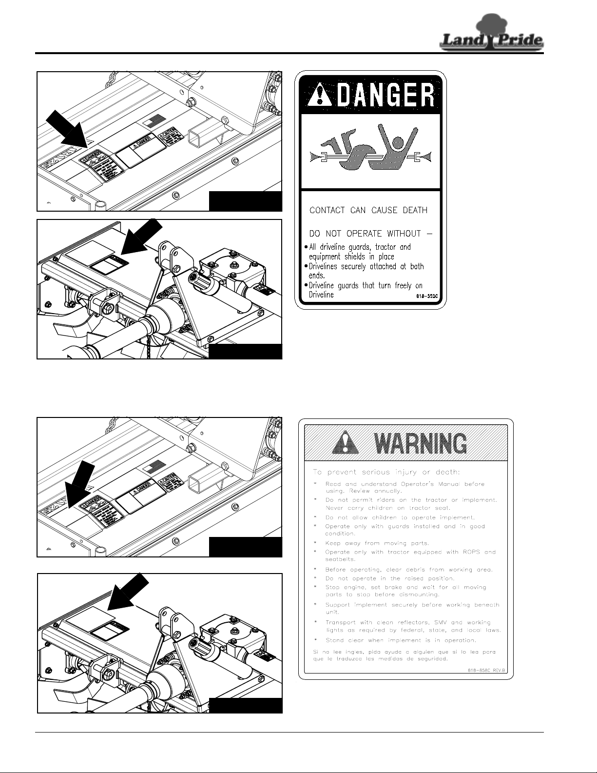
ROTATING DRIVELINE
KEEP AWAY!
818-552C
Rotating Driveline Hazard - Keep
Away!
30346A
30361A
RTR12 & RTA12 Series (Serial No. 884764-) Rotary Tillers 311-785M
6
RTR12 Series
RTA12 Series
818-858C
General Safety Instructions
8/12/14
Page 9
Land Pride
Important Safety Information
Table of Contents
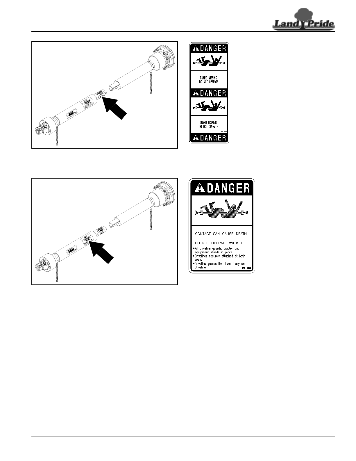
818-540C
RTR & RTA Series
Shield missing - Do Not operate.
30370
30370
ROTATING DRIVELINE
KEEP AWAY!
818-552C
RTR & RTA Series
Rotating Driveline Hazard Keep Away!
8/12/14
RTR12 & RTA12 Series (Serial No. 884764-) Rotary Tillers 311-785M
7
Page 10
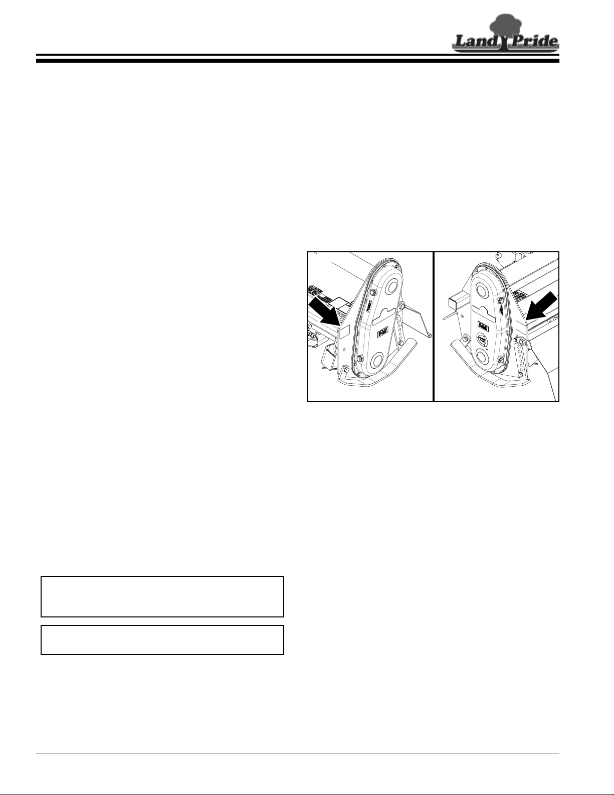
Table of Contents
Introduction
Introduction
Land Pride welcomes you to the growing family of new
product owners.
This Rotary Tiller has been designed with care and built
by skilled workers using quality materials. Proper
assembly, maintenance,andsafeoperatingpracticeswill
help youget years of satisfactory use from this machine.
Application
The RTR12 and RTA12 Series Rotar y Tillers are
designed and built by Land Pride to till soil for seedbed
and planting preparation with uses and applications in
landscaping, gardens, and residential areas. They are
adapted for 15-50 horsepower tractors with Category I
three-point hitch mounting, 540 rpm PTO speed and are
Quick-Hitch adaptable.
The reverse rotation tillers (RTR Series) tend to achieve
greater depth penetration resulting in moving and
pulverizingmore soil. Also, theybury more of the residue
in the soil.
See “Specifications & Capacities” on page 28 and
“Features & Benefits” on page 30 for additional
information.
The parts on your Rotary Tiller have been specially
designedbyLand Prideand shouldonly be replacedwith
genuine Land Pride parts.Contact a Land Pride dealer if
customer service or repair parts are required. Your Land
Pride dealer has trained personnel, repair parts, and
equipment needed to service the implement.
Serial Number
Model No. _____________Serial No. _______________
For quick reference and prompt service, record model
number and ser ial number in the spaces provided above
and again on warranty page 33. Always provide model
and serial number when ordering parts and in all
correspondences with your Land Pride dealer. Refer to
Figure 1 for location of your serial number plate.
30364A
30357A
Using This Manual
This Operator’s Manual is designed to help familiarize
•
you with safety, assembly, operation, adjustments,
troubleshooting, and maintenance. Read this manual
and follow the recommendations to help ensure safe
and efficient operation.
• The information contained within this manual was
current at the time of printing. Some parts may change
slightly to assure you of the best performance.
• To order a new Operator’s or Parts Manual, contact
your authorized dealer. Manuals can also be
downloaded, free-of-charge, from our website at
www.landpride.com
Terminology
“Right” or “Left” as used in this manual is determined by
facingthe direction the machine will operate while in use
unless otherwise stated.
Definitions
IMPORTANT: A special point of information related
to the following topic. Land Pride’s intention is this
information must be read & noted beforecontinuing.
NOTE: A special point of information that the
operator should be aware of before continuing.
Owner Assistance
The Online Warranty Registration should be completed
by the dealer at the time of purchase. This information is
necessary to provide you with quality customer service.
RTA Series RTR Series
Serial Number Plate Location
Figure 1
Further Assistance
Your dealer wants you to be satisfied with your Rotary
Tiller. If for anyreason you do not understand any part of
thismanual or are not satisfiedwith the service received,
the following actions are suggested:
1. Discuss the matter with your dealership ser vice
manager making sure that person is aware of any
problemsyou mayhave and has had the opportunity
to assist you.
2. If you are still not satisfied, seek out the owner or
general manager of the dealership, explain the
problem, and request assistance.
3. For further assistance write to:
Land Pride
Service Depar tment
P.O. Box 5060
Salina, Ks. 67402-5060
E-mail address
lpservicedept@landpride.com
RTR12 & RTA12 Series (Serial No. 884764-) Rotary Tillers 311-785M
8
8/12/14
Page 11
Land Pride
Table of Contents
Section 1: Assembly and Set-Up
Section 1: Assembly and Set-Up
Dealer Preparations
!
CAUTION
To avoid bodily injury caused by accidental falling of tiller,
securely support tiller on safe supporting stands or blocks.
This unit is shipped almost completely assembled.
Carefully follow instructions for final assembly.
Before attempting assembly check the following items.
Having all the needed parts and equipment readily at
hand will speed up your assemblytask and will makethe
job as safe as possible.
• Check for fasteners and pins that were shipped with
the tiller. Small hardware shipped loose from the
factoryis contained ina bag. Largerparts are attached
to the shipping crate.
• Have ready for the assembly task a fork lift or loader
along with chains and safety stands sized for the job.
• Have a minimum of 2 people on handduring assembly. Tractor Requirements
Tractor horsepower should be within the range noted
below. Tractors outside the horsepower range must not
be used.
Hitch Category . . . . . . . . . . . . . . . . . . . . 3-Point Cat. I
PTO Speed . . . . . . . . . . . . . . . . . . . . . . . . .540 RPM
Horsepower Requirements:
42" & 50" widths . . . . . . . . . . . . . . . . . . .15-35 HP
58" & 66" widths . . . . . . . . . . . . . . . . . . . . 20-40 HP
74" Width . . . . . . . . . . . . . . . . . . . . . . . . .25-50 HP
!
WARNING
Ballast weights may be required to maintain steering control.
Refer to your tractor Operator’s Manual to determine proper
ballast requirements.
Torque Requirements
Check to make sure all nuts are tightened. Refer to
“Torque ValuesChart” on page 32 to determine correct
torque values for common bolts. See “Additional
Torque Values” at bottom of chart for exceptions to
standard torque values.
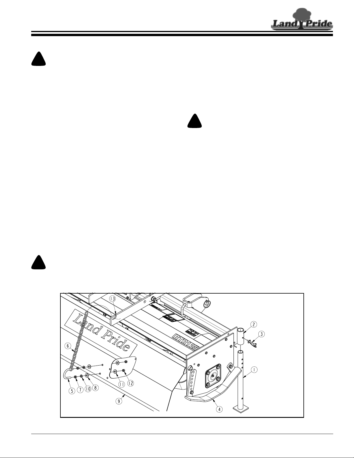
RTR & RTA Parking Stand Installation
Refer to Figure 1-1:
!
CAUTION
To avoid bodily injury caused by accidental falling of tiller,
stabilize unit with parking stand and support blocks.
1. Insert parking stand (#1) in support tube (#2).
2. Adjust parking stand to a height that will suppor t the
tiller level while resting on skid shoes (#4).
3. Secure parking stand with wire retaining pin (#3).
Makesure wire retainer ishooked over the end of the
retaining pin.
RTR & RTA Rear Chain Installation
Refer to Figure 1-1:
1. Insert u-bolt (#5) into one end of rear chain (#6).
2. Install two nuts (#7) onto u-bolt an equal distance
from the threaded end.
3. Insert u-bolt through lock washers (#10), flat
washers (#8), and holes in deflector shield (#9) that
are most vertically located under slot (#13).
4. Secure u-bolt (#5) to deflector shield (#9) with flat
washers (#11) and 3/8"-16 hex nuts (#12). Draw hex
nuts (#12) up snug and tighten hex nuts (#10) to the
correct torque.
5. Attach opposite end of rear chain (#6) to slot (#13).
8/12/14
RTR Series Shown
Support Leg & Rear Deflector Chain Assembly
Figure 1-1
RTR12 & RTA12 Series (Serial No. 884764-) Rotary Tillers 311-785M
30728A
9
Page 12

Section 1: Assembly and Set-Up
Table of Contents
Reverse Rotation (RTR) Rotary Tillers
The following are assembly instructions for reverse
rotation tillers (RTR12 Series). Seepage 12 forstandard
rotation tillers (RTA12 Series).
IMPORTANT: Parking stand (#1) and wire retaining
pin (#7) must be installed at the correct height
before continuing. See “Parking Stand Installation”
on page 9 for special instructions.
RTR Front Deflector Assembly
Refer to Figure 1-2:
1. Remove3/8"-16x 1 1/2" bolts (#3),flatwashers (#5),
lockwashers (#6), hex nuts (#4) and both front
deflector mounting bars (#2) from tiller frame.
2. Insert 3/8"-16 x 1 1/2" GR5 hex head bolts (#3)
through flat washers (#5), upper mount bar (#2A),
front rubber deflector (#8) and mounting holes “A”.
3. Securerubber deflector andupper mountingbarwith
lower mount bar (#2B), lock washers (#6) and hex
nuts (#7).
4. Tighten hex nuts to the correct torque.
RTR Parking Stand and Front Deflector Assembly
RTR12 & RTA12 Series (Serial No. 884764-) Rotary Tillers 311-785M
10
30348A
Figure 1-2
8/12/14
Page 13

Land Pride
Section 1: Assembly and Set-Up
Table of Contents
RTR 3-Point Hitch Assembly
Refer to Figure 1-3:
1. Install upper right-hand hitch plate (#4) to gearbox
mounting frame with 5/8"-11 x 1 3/4" GR5 cap
screw(#6),lockwashers(#14), andhexnuts(#9). Do
not tighten hardware at this time.
2. Repeat step 1 above to Install upper left-hand hitch
plate (#3) to gearbox mounting frame.
3. Install 1 1/4
hitch plates (#4 & #5) with 3/4
screw (#7), lockwasher (#15) and hex nut (#10).
4. Tighten all hex nuts (#9 & #10) to the correct torque.
5. Attach manual storage tube (#18) to hitch plate (#3)
with 1/4
washers (#13) and nylock hex nuts (#12) as shown.
Tighten nuts to the correct torque.
6. Attach left-hand clevis (#5) to the square tube with
1/2" u-bolt (#17) and 1/2" hex lock nuts (#11). Do
Not Tighten lock nuts.
7. Repeat step 6 above for the right-hand clevis.
" OD spacer (#1) between upper 3-Point
"-10 x 4" GR5 cap
"-20 x 1 1/4" GR5 cap screws (#8), flat
Refer to Figure 1-4:
8. Position clevises 26 7/8
" apart from inside of clevis
plate to inside of clevis plate and centered off the
gearbox input shaft 13 7/16
" as shown.
Refer to Figure 1-3:
9. Tighten u-bolt locknuts (#11) to the correct torque.
10. Skip to “Tractor Hook-Up” instructions on page 13.
13 7/16"
26 7/8"
Clevis Location (RTR Series Shown)
Figure 1-4
30349A
8/12/14
RTR 3-Point Hitch & Driveline Assembly
Figure 1-3
RTR12 & RTA12 Series (Serial No. 884764-) Rotary Tillers 311-785M
30347A
11
Page 14

Section 1: Assembly and Set-Up
Table of Contents
Standard Rotation (RTA) Rotary Tillers
The following are assembly instructions for standard
rotation tillers (RTA12 Series). See page 10 for reverse
rotation tillers (RTR12 Series).
IMPORTANT: Parking stand (#3) and wire retaining
pin (#20) must be installed at the correct height
before continuing. See “Parking Stand Installation”
on page 9 for special instructions.
RTA 3-Point Hitch Assembly
Refer to Figure 1-5:
1. Install upper right-hand hitch plate (#6) to gearbox
mounting frame with 5/8"-11 x 1 3/4" GR5 cap
screws (#9), spr ing lockwashers (#17), and hex
nuts (#12). Do not tighten hardware at this time.
2. Repeat step 1 to Install upper left-hand hitch
plate (#5) to gearbox mounting frame.
3. Install 1 1/4" OD spacer (#1) between upper 3-Point
hitch plates (#5 & #6) with 3/4"-10 x 4" GR5 cap
screw (#10), lockwasher (#18) and hex nut (#13).
4. Tightenall hexnuts (#12 & #13) to the correct torque.
5. Attach manual storage tube (#22) to hitch plate (#5)
with 1/4"-20 x 1 1/4" GR5 cap screws (#11), flat
washers(#116) and nylockhexnuts (#15)as shown.
Tighten nuts to the correct torque.
6. Install driveline guard (#7) on backside of 3-Point
hitch plates with four 5/16" wing screws (#8).
7. Attach left-hand clevis (#4) to the square tube with
1/2" u-bolt (#21) and 1/2" hex lock nuts (#14). Make
certain clevis is oriented with hitch pin holes closest
to the top and the longer chamfer is on the bottom.
Do Not Tighten lock nuts.
8. Repeat step 7 above for the right-hand clevis.
RTA Parking Stand, 3-Point Hitch & Driveline Assembly
RTR12 & RTA12 Series (Serial No. 884764-) Rotary Tillers 311-785M
12
30363A
Figure 1-5
8/12/14
Page 15

Land Pride
Section 1: Assembly and Set-Up
Table of Contents
Refer to Figure 1-6:
9. Position clevises 26 7/8" apart from inside of clevis
plate to inside of clevis plate and centered off the
gearbox input shaft 13 7/16" as shown.
Refer to Figure 1-5 on page 12:
10. Tighten u-bolt locknuts (#15) to the correct torque.
30349A
13 7/16"
26 7/8"
Clevis Location (RTA Series Shown)
Figure 1-6
Tractor Hook-Up
!
DANGER
A Crushing Hazard exists when hooking-up equipment to a
tractor. Do not allow anyone to stand between tractor and
implement while backing-up to implement. Do not operate
hydraulic 3-point lift controls while someone is directly
behind the tractor or near the implement.
!
WARNING
Lifting unit morethan 14" above ground with PTO engaged or
engaging PTO with unit higher than 14" above ground can
break the driveline and could cause flying projectiles.
!
CAUTION
To avoid bodily injury caused by accidental falling of tiller,
stabilize unit with parking stand and support blocks.
Refer to Figure 1-7:
1. Backtractorup to tilleruntil lower3-Pointliftarms are
aligned with tiller hitch clevises.
2. Securetractor’s3-Pointlower hitch arms to the lower
hitch clevisesusing 7/8" diameter hitch pins. Secure
hitch pins with linch pins.
3. Secure tractor’s top center link to tiller hitch plates
using 3/4" diameter hitch pin (supplied bycustomer).
4. Place a levelon the end plate and adjust tractor’stop
center link to level tiller from front to back.
5. Place levelon the square tube and adjust one of the
two tractor’s lower 3-Point arms up or down to level
tiller from left to right.
IMPORTANT: Tokeep parkingstand frombecoming
damaged, always store stand in the transport
position before moving tractor with tiller attached.
6. Raise tiller up and remove parking stand from its
mounting tube. Turn parking stand upside down and
reinsert it several inches through the top of the
mounting tube. Secure parking stand using one of
the upper three holes with existingwire retaining pin.
7. Raise tiller fully up with 3-Point lift. Measure the
distancetines areoff theground. Ifdistance exceeds
14", adjust tractor’s 3-Point lift height limiter until
tines will not lift higher than 14 inches off the ground.
8. Continue with “Driveline Installation” on page 13.
Driveline Installation
The tiller driveline is coupled to the tractor shaft with
a push-pin coupler and to the implement shaft with a
boltedcoupler.A slip clutch is providedon the implement
end for protection from shock loads.
Always engage PTO at low engine r pm to minimize
start-up torque. Drivelines with friction slip clutches
must go through a “run-in” operation prior to initial
use and after long periods of inactivity. See
“Driveline Protection” on page 22 for detailed
instructions on maintaining the slip clutch.
If the Rotary Tiller is used on more than one tractor,an
additionaldriveline mayberequired -especially ifa quick
hitch is used.
8/12/14
30360
Tractor Hook-Up
Figure 1-7
RTR12 & RTA12 Series (Serial No. 884764-) Rotary Tillers 311-785M
13
Page 16

Table of Contents
Section 1: Assembly and Set-Up
!
DANGER
Do not engage tractor PTO while hooking-up and unhooking
driveline or while someone is standing near the driveline. A
person’s body and/or clothing can become entangled in the
driveline resulting in serious injury or death.
!
WARNING
Do not use a PTO adaptor with a quick hitch. A PTO adapter
will increase strain on the tractor’s PTO shaft resulting in
possible damage to shaft and driveline.
4. Attach other end of driveline to tractor PTO shaft.
5. Move driveline yokes back and forth to ensure both
ends are secured to the shafts. Reattach any yoke
that is loose.
NOTE: If driveline is too long to fit between tractor
and tiller, skip to “Shorten Driveline” on page 15.
IMPORTANT: Two safety chains are supplied with
the driveline.To keepdriveline shields from rotating,
thesechains mustbe attachedto theouter andinner
driveline shields and to the tiller and tractor.
!
DANGER
All guards and shields must be installed and in good working
condition at all times during tiller operation.
!
WARNING
Always disengage PTO, put gear selector in park or set park
brake, shut off tractor, remove ignition key, and wait for all
moving parts to come to a complete stop before dismounting
tractor.
!
WARNING
Do not over speed PTO or machine breakagemay result.Some
tractorsare equipped with multispeed PTOranges. Be certain
your tractor’s PTO is set for 540 rpm.
IMPORTANT: The driveline must be lubricated
before putting it into service. Refer to “Lubrication
Points” on page 25 for detailed instructions.
IMPORTANT: Drivelines with friction clutches must
go through a “run-in” operation prior to initial use
and after long periods of inactivity.See “Driveline
Protection” on page 22 for detailed instructions.
IMPORTANT: If tiller is to be used on more than one
tractor, an additional driveline may be required,
especially if a quick hitch is used.
6. Attach safety chain on the outer driveline shield to
thetractor frameto restrictouter shieldfrom rotating.
Re-latch safety chain to outer driveline shield.
7. Attach safety chain on the inner driveline shield to
the tiller frame to restr ict inner shield from rotating.
Re-latch safety chain to inner driveline shield.
Check Driveline Collapsible Length
Refer to Figure 1-8:
IMPORTANT: A driveline that is too long can bottom
out causing structural damage to tractor and tiller.
Alwayscheckdrivelinecollapsedlength duringinitial
setup, when connecting to a different tractor, and
when alternating between using a quick hitch and a
standard 3-point hitch. More than one driveline may
be required to fit all applications.
1. Make sure dr iveline is installed properly before
checking driveline collapsed length (Refer to
“Driveline Installation” instructions on page 13).
2. With driveline level, measure 1" (“B” dimension)
back from universal joint shield to end of outer
driveline shield as shown in Figure 1-8.
a. If measurement is less than 1", shorten driveline.
a. If measurement is 1” or more, skip to “Check
Driveline Maximum Length” on page 15.
IMPORTANT: The tractor’s PTO shaft and tiller
gearbox shaft must be aligned and level with each
other during installation of driveline. This alignment
is the shortest distance between the two shafts.
1. Parktractorand tilleron alevelsurface.Raisetiller to
aligngearbox input shaft levelwith tractor PTOshaft.
Securely block tiller at this height to keep unit from
lowering while attaching the dr iveline.
2. Place gear selector in park, shut tractor engine off,
set park brake and remove switch key.
Refer to Figure 1-3 on page 11 for RTA12 or
Figure 1-5 on page 12 for RTR12
3. Remove gearbox shaft protector (#24) from end of
gearbox shaft and attach slip clutch end of
driveline (#25) to gearbox input shaft.
RTR12 & RTA12 Series (Serial No. 884764-) Rotary Tillers 311-785M
14
30563
Driveline Shortening
Figure 1-8
8/12/14
Page 17

Land Pride
Section 1: Assembly and Set-Up
Table of Contents
Shorten Driveline
Refer to Figure 1-8 on page 14:
Be sure to first check driveline collapsed length as
instructed above. If required, shorten drivelineas follows:
1. Un-hook driveline from tractor PTO shaft and pull
outer and inner drivelines apart.
2. Reattach outer dr iveline to tractor PTOshaft. Pull on
inner and outer drivelines to be sure universal joints
are properly secured.
3. Holdinner and outerdrivelines parallel to each other:
a. Measure 1" (“B” dimension) back from outer
drivelineuniversal jointshield and makea markat
this location on the inner driveline shield.
b. Measure 1" (“B” dimension) back from the inner
drivelineuniversaljoint shieldand makea mar k at
this location on the outer driveline shield.
4. Removedriveline and safety chains from tractor and
gearbox.
5. Measure from end of inner shield to scribed mark
(“X” dimension). Cutoff innershield at the mark. Cut
same amount off the inner shaft (“X1” dimension).
6. Measure from end of outer shield to scribed mark
(“Y” dimension). Cutoff outershield at themark. Cut
same amount off the outer shaft (“Y1” dimension).
7. Remove all burrs and cuttings.
8. Continuewith“Check Driveline Maximum Length”.
Check Driveline Maximum Length
Refer to Figure 1-9:
Thedrivelinemaximum allowablelength must,when fully
extended,haveaminimum overlap ofthe profiletubes by
notless than 1/3 the free length with bothinner and outer
profile tubes being of equal length.
1. Ifnot already completed,apply multi-purposegrease
to inside of outer profile and reassemble driveline.
2. Assemblethe twodriveline profiles together with just
1/3 overlapping of the profile tubes as shown below.
Onceassembled, measureand recordthe maximum
allowable length for future reference.
Record Maximum Allowable Length here: ________
3. Reattach driveline to tractor and gearbox shaft
following “Driveline Installation” steps 1 to 7 on
page 14.
4. Continue with “Check Driveline Interference”.
Check Driveline Interference
1. Start tractor and raise Rotary Tiller just enough to
remove support blocks from under tiller.
2. Slowly engage tractor hydraulic3-Point control lever
to lower tiller while checking for sufficient drawbar
clearance. Move drawbar ahead, aside or remove if
required.
Refer to Figure 1-10:
!
WARNING
Lifting unit morethan 14" above ground with PTO engaged or
engaging PTO with unit higher than 14" above ground can
break the driveline and could cause flying projectiles.
!
WARNING
The driveline must not exceed an angle of 25 degrees up or
down while operating. Exceeding this angle with driveline
rotating can break the driveline and cause flying projectiles.
3. With PTO off, raise implement fully up and make the
following checks below. If driveline exceeds any of
the limits listed, set tractor 3-Point lift limiter at a
heightthat willkeep the driveline within its lift limits to
avoid premature driveline breakdown.
• Tines do not exceed more than 14" off the ground.
• Driveline does not exceed 25
o
up.
• Driveline does not exceed maximum allowable
length recorded in step 2 under “Check Driveline
Maximum Length” on this page.
24513
Outer Shielding has been removed for clarity.
Driveline Maximum Length
Figure 1-9
8/12/14
Maximum PTO Driveline Movement During Operation
Figure 1-10
RTR12 & RTA12 Series (Serial No. 884764-) Rotary Tillers 311-785M
24872
15
Page 18

Table of Contents
Section 2: Operating
Section 2: Operating
Operating Checklist
Hazard control and accident preventionare dependent
upon the awareness, concern, prudence, and proper
training involved in the operation, transport,
maintenance,andstorage of theRotaryTiller. Therefore,
it is absolutely essential that no one operates the Rotar y
Tiller without first having read, fully understood, and
becometotally familiarwith the Operator’sManual.Make
sure the operator has paid particular attention to:
• Important Safety Information, pages 1 to 7
• Section 1: Assembly and Set-Up, page 9
• Section 2: Operating, page 16
• Section 3: Adjustments, page 20
• Section 4: Maintenance and Lubrication, page 22
Safety Information
!
DANGER
Do not engage tractor PTO while hooking-up and unhooking
driveline or while someone is standing near the driveline. A
person’s body and/or clothing can become entangled in the
driveline resulting in serious injury or death.
!
Keep yourself and all others away from rotating tines and
drive train. Always disengage PTO and lockout power source
before making adjustments or servicing the tiller. A person’s
body, hair, or clothing can become entangled in rotating
components causing serious bodily injury or death.
DANGER
Inspections
Make the following inspections with tiller attached to a
tractor, PTO disengaged and completely stopped.
Operating Checklist
✔ Check
Inspect tractor safety equipment to make sure it is in
good working condition.
Check all guards and shields to make certain they are in good
working condition, in place and secured.
Carefully raise and lower implement to ensure drawbar , tires , and
other tractor parts do not contact tiller frame or PTO driveline.
Check driveline to be sure it is securely connected to
tractor PTO shaft and tiller gearbox shaft.
Refer to “Driveline Installation”.
Check drive chain tension.
Refer to “Drive Chain Tension”.
Check tiller depth setting.
Refer to “Skid Shoe Adjustment”.
Checkdriveline slip clutch to make sure disks will slip.
Refer to “Driveline Protection”
Check for worn, bent, broken, loose and/or missing
tines. Replace tines as needed.
Refer to “Tine Replacement”
Grease driveline shaft and all other grease fittings
Refer to“Lubrication Points”.
Check oil level in gearbox. Make sure all plugs
have been replaced when completed.
Refer to “Gearbox Lubrication”.
Checkoillevelin chaincase. Make sure all plugs have
been replaced when completed.
Refer to “Chaincase Lubrication”.
Checktiller initially and periodically for loose bolts and
pins. Refer to “Torque Values Chart for Common Bolt
Sizes” for torque values .
Page No.
SeeTractor
Manual
Page 13
Page 20
Page 21
Page 22
Page 22
Page 25
Page 26
Page 26
Page 32
!
DANGER
Keep away from the rotating hex drive shaft between the
gearbox and chaincase. A person can become entangled in the
shaft causing serious bodily injury or death.
!
DANGER
Make all 3-point hydraulic adjustments from the tractor seat.
Never make hydraulic adjustments while standing alongside
the tractor or behind the tractor.
!
DANGER
PTO shaft shield, gearbox shields, driveline shields, and
driveline safety chains must be installed and in good working
condition while operating tiller to avoid injury or death from
entanglement in a rotating driveline.
!
DANGER
Do not operate a brokenor bent driveline. Such drivelines can
break apart while rotating at high speeds causing serious
injury or death. Always remove Rotary Tiller from service
until damaged drivelines are repaired or replaced.
!
DANGER
Clear areaof debris beforetilling.Mark any potential hazards
that cannot be removed such as treestumps, post, rocks,holes,
and drop-offs with a visible flag.
!
DANGER
Keep front rubber dirt deflector on the RTR tiller in place
while operating the unit. Objects can be thrown forward
toward the operator causing serious bodily injury or death.
RTR12 & RTA12 Series (Serial No. 884764-) Rotary Tillers 311-785M
16
!
DANGER
Do not point outlet toward people, animals, or buildings and
keep people and animals away from outlet during operation.
Tine impact on objects can cause projectiles resulting in
bodily injury or death.
8/12/14
Page 19

Land Pride
Section 2: Operating
Table of Contents
!
DANGER
Do not till across steep inclines exceeding 15 degrees. The
action of the tines being forced down into the ground can
cause the tractor to roll-over resulting in serious injury or
death. Consult your tractor’s manual for acceptable inclines
the tractor is capable of traveling across.
!
DANGER
Always disengage PTO before lifting tiller up and never
operate tiller in the raised position. The tiller can discharge
objects at high speeds resulting in injury or death.
!
DANGER
Do not use tiller as a working platform. The tiller is not
properly designed or guarded for this use. Using tiller as a
working platform can cause serious injury or death.
!
WARNING
Never allow children or other riders on the tractor or tiller.
They can fall and be ran over causing serious injury or death.
!
WARNING
Do not use a PTO adaptor with a quick hitch. A PTO adapter
will increase strain on the tractor’s PTO shaft resulting in
possible damage to shaft and driveline.
!
WARNING
Use Rotary Tiller for its intended purpose only. Do not use
tiller to lift or carry objects; to pull fence posts, stumps, or
other objects; or to tow other equipment. Doing so can
damage the tiller, cause serious bodily injury, or death.
!
WARNING
Do not operate tiller with loose pins, bolts and nuts. Loose
hardware can result in a serious breakdown causing bodily
injury or death.
!
WARNING
Do not over speed PTO or machine breakagemay result.Some
tractorsare equipped with multispeed PTOranges. Be certain
your tractor’s PTO is set for the tiller’s rated PTO speed. See
Specifications & Capacities for rated PTO speed.
!
CAUTION
Make certain you are not working over any underground
wiring, pipes, or other obstructions. If there is doubt, contact
your local utility services so that they may mark the location
of all underground utilities in the area. Be sure to ask how
close you can work to the marks or flags they positioned.
IMPORTANT: Make sure all safety labelsare in their
proper location and in good condition before
operation. Follow all directions on the safety labels.
IMPORTANT: Do not alter tiller in a way which will
adversely affect its performance or reliability or use
the tiller for a pur pose for which it was not designed.
NOTE: To protect the parking stand from becoming
bent while transporting and tilling the soil, always
store it upside down in its mount.
!
WARNING
Always disengage PTO, put gear selector in park or set park
brake, shut off tractor, remove ignition key, and wait for all
moving parts to come to a complete stop before dismounting
tractor.
!
WARNING
Always make certain driveline yokes aresecuredto the tractor
PTO shaft and gearbox input shaft before engaging PTO. A
loose driveline can slip off the end of a connected shaft while
rotating and cause serious bodily injury or death.
!
WARNING
Do not allow anyone to operate this Rotary Tiller who has not
been properly trained in its safe operation or anyone who is
under the age of 16.
8/12/14
RTR12 & RTA12 Series (Serial No. 884764-) Rotary Tillers 311-785M
17
Page 20

Section 2: Operating
Table of Contents
Transporting
Refer to Figure 2-1:
!
CAUTION
When traveling on public roadswhether at night or during the
day,use accessory lights and devices for adequate warning to
operatorsof other vehicles. Comply with all federal,state,and
local laws.
IMPORTANT: AlwaysdisengagePTObeforeraising
tiller to transport position.
1. When raising tiller to transport position, be sure the
driveline does not contact tractor or tiller. Adjust
tractor’s3-Pointhitch lift height so that the tiller tines
are not lifted more than 14 inches off the ground to
prevent driveline damage.
Refer to Figure 2-1:
2. Remove parking stand (#4) from support tube, turn
stand upsidedown and replace through top of
support tube as shown. Secure stand with wire
retaining pin (#5).
Parking
Thefollowingstepsshould be takenwhenpreparing to store
the tiller or unhitch it from the tractor.
IMPORTANT: It is impor tant to adjust skid shoes
down to stabilize the tiller when parked.
Refer to Figure 2-2:
1. Adjust right-hand skid shoes (#1) down before
unhitching tiller from the tractor:
a. Loosening pivot bolt (#2A) at the shoe’s front.
b. Remove adjusting bolt (#2B) at the shoe’s rear.
c. Pivot skid shoe downand replace pivot bolt (#2B)
and lock washer (#3) in the second hole down
from the top as shown.
d. Tighten bolts (#2A & #2B) to the correct torque.
2. Repeat step 1 to adjust the left-hand skid shoe down.
3. Remove parking stand (#5) from support tube, turn
stand upright and replace it through bottom of
support tube.
4. Set parking stand (#5) to desired height for re-hookup and install wire retaining pin (#4) to lock in place.
5. Park tiller on a level, solid area. Shut tractor engine
off and engage parking brake.
6. Unhitch tiller from tractor.
30350A
Parking Stand in Transport Position
Figure 2-1
3. Be sure to reduce tractor ground speed when
turning, and leave enough clearance so tiller does
not contact obstacles such as buildings, trees or
fences.
4. Select a safe ground travelspeed when transporting
from one area to another. When traveling on
roadways,transport in sucha waythat fastermoving
vehicles may pass you safely.
5. Whentravelingoverroughor hillyterrain, shift tractor
to a lower gear.
!
WARNING
Place support blocks under tiller as needed to prevent unit
fromtipping over onto a childand/or an adult. A tiller that tips
over can result in injury or death.
7. After unhooking tiller, check tiller for stability by
physically applying pressure at the hitch plates to
see if it will tip forward or backwards. If the tiller
moves in either direction, then block under the tiller
as needed to prevent that movement.
8. See “Storage” on page 24 for additional information
on long term storage of your tiller.
30351A
Parking Stand & Skid Shoe in Parking Position
Figure 2-2
RTR12 & RTA12 Series (Serial No. 884764-) Rotary Tillers 311-785M
18
8/12/14
Page 21

Land Pride
Section 2: Operating
Table of Contents
General Operating Notes
Beforebeginning totill the following inspection should be
performed:
1. Check oil level in gearbox and chaincase. Refer to
“Lubrication Points” on page 25.
2. Check that all plugs have been replaced properly in
the gearbox and chaincase.
3. Be sure all tiller tines, bolts, and nuts are tight.
4. Be certain all guards, shields, and dirt deflectors are
in place and secure.
5. Grease driveline shaft and all other grease fittings.
Refer to “Lubrication Points” on page 25.
6. Clear area to be tilled of rocks, branches, and other
foreign objects.
7. Tall grass and weeds should be mowed before tilling.
8. Do not engage PTO at full throttle. Once engaged,
increase throttle to 540 PTO speed. Tiller tines will
cut better at 540 PTOspeed than at reduced throttle.
9. Tilling should not be done in wet conditions as soil
will stick to tines.
10. At first begin tilling at a slow forward speed and shift
up as ground conditions warrant.
11. Operated tiller with deck level to the ground.
12. Tiller should be operated with the tiller deck level to
the ground.
13. Tiller tines will cut better when operating the tractor
at full 540 rpm PTO speed than at reduced throttle.
14. After tillingthe first 50feet,stop andchecktosee that
the tiller is adjusted properly.
15. Do not maketurns or attempt to back up while tiller is
in the ground. See important note below.
IMPORTANT: Turning or backing up with rotary
tines in the ground will damage the tiller.
16. Do not engage PTO with machine in the fully raised
or lowered position.
17. Periodically check for foreign objects wrapped
around the rotor shaft and remove them after
disengaging PTO, turning off tractor engine, and
removing ignition key.
General Operating Instructions
Before using your Land Pride RTR12 or RTA12 Series
Rotary Tiller, you should have completely read the
Operator’s Manual, properly attached the tiller to the
tractor, cut the driveline to proper length, run-in the
clutch, and gone through the Operating Checklist. If you
have missed any of these steps, please complete them
before proceeding.
Now that you have properly prepared yourself and your
tiller,it’stime todo sometilling. Carefully dr ive thetractor
to the site where you intend to till. You should have
already cleaned this site of any large limbs, rocks,
trash, metal or other debris. Best results will be
achievedifyou have mountedyour tiller offset tothe right
far enough to cover the tread of your right tractor wheel.
Linethe tractor upjust tother ight ofcenter onyourtillage
plot. You will be working from the center out and always
turning to the r ight to line up for your next pass.
Lower the tiller half way to the ground and reduce your
tractor engine speed to about one quarter throttle.
Engage the PTO and gradually increase the engine
speed until you reach full PTO speed of 540 rpm. Lower
the tiller to the ground and simultaneously commence
forwardtravelof approximately2mph. Do notmake turns
or attempt to back up while tiller is in the ground. See
important note below.
IMPORTANT: Turning or backing up with rotary
tines in the ground will damage the tiller.
Travel about 50 ft. and then stop to check your results.
When stopping, remember to lift the tiller out of the
ground, stop the tractor, reduce engine speed,
disengage the PTO, set the par k brake, shut off the
tractor,and removethe keys.If you are tilling too shallow
or too deep, adjust the skid shoes accordingly. If the soil
textureis too coarse,lower the rear deflector and reduce
your ground speed. If the soil texture is too fine, you will
need to raise your rear deflector and increase your
groundspeed.Foranyother problemconditionsthatmay
arise,youwill wanttoreferto the Troubleshootingsection
on page 27.
When youare done tilling forthe day, make sure you use
propertractor shutdown procedures beforeyou get off of
thetractor.If you are detaching yourtiller, makesure you
park it on a dry and level surface leaving it clean and
ready forthe next use. When you put yourtiller up for the
season,make sure youreferto theStorage Directionson
page 24.
With a little practice and a fewadjustments,you will soon
be achieving the results you want with your Land Pride
Rotary Tiller. See “Features and Benefits” Section 6
or “Specifications and Capacities” Section 5 for
additional information and performance enhancing
options.
8/12/14
RTR12 & RTA12 Series (Serial No. 884764-) Rotary Tillers 311-785M
19
Page 22

Table of Contents
Section 3: Adjustments
Section 3: Adjustments
RTA & RTR12 Tiller Hitch Offset
Refer to Figure 3-1:
!
CAUTION
Do not exceed offsetting tiller 7" left or right of gearbox input
shaft. Doing so can breakthe driveline, tractorPTO,and tiller
gearbox.
!
CAUTION
After offsetting, check to see that the driveline clears all
shields on the tiller, tractor, and tiller hitch. If not, decrease
offset until clearance is obtained.
Except for RTA1242, the RTA12 & RTR12 Series tillers
can be shifted a maximum offset of 7" left or right of the
gearbox input shaft by moving the hitch clevises (#1)
7
" to the right or left.
The RTA1242 is built to be offset 5" to the right when the
hitch clevis are set an equal distance away from the
gearbox input shaft. The unit can be shifted a maximum
of 7" to the left by moving the hitch clevis 7" to the right.
For best tillage results, adjust tiller offset to the right by
moving the hitch clevisto the left far enough to cover the
tractor’s r ight rear wheel tread marks.
1. Loosen hex nuts (#2) until clevises (#1) can be
moved on the front tube.
2. Slide lower hitch clevises (#1) an equal amount left
or right up to 7" while holding the 26 7/8" distance
between clevises.
3. Retighten hex nuts (#2) to the correct torque value.
Adjust Clevis Left or Right
Up To 7" Maximum
Adjust
To Suit
Hold 26 7/8"
30352
Clevis Offset
Figure 3-1
Torque L.H. Jam Nut
Counterclockwise to 400 ft-lbs.
Arrow showing
Counterclockwise Rotation
Drive Chain Tension
The drive chain tension can be adjusted by rotating the
chain tightener stud. Should excessivechain backlash
occur, tighten stud as noted below.
RTR12 Series Tillers
Refer to Figure 3-2:
IMPORTANT: Jam nut has left-hand threads.
Loosen nut by turning it clockwise.
1. Loosen jam nut and torque chain tightener stud
counterclockwise 20 to 30 ft-lbs.
2. Retighten jam nut to 400 ft-lbs. Be sure to hold chain
tightener stud in position while tightening jam nut.
RTA12 Series Tillers
Refer to Figure 3-3:
IMPORTANT: Chain tightener nut has right-hand
threads. Loosen nut by turning it counterclockwise.
1. Loosen jam nut and torque chain tightener stud
clockwise 20 to 30 ft-lbs.
2. Retighten jam nut to 400 ft-lbs. Be sure to hold chain
tightener stud in position while tightening jam nut.
RTR12 Series Chain Tightener
Arrow Showing
Clockwise Rotation
30371A
RTA12 Series Chain Tightener
Torque Chain Tightener Stud
Counterclockwise 20 to 30 ft-lbs.
Figure 3-2
Torque R.H. Jam Nut
Clockwise to 400 ft-lbs.
Torque Chain Tightener Stud
Clockwise 20 to 30 ft-lbs.
Figure 3-3
30353A
RTR12 & RTA12 Series (Serial No. 884764-) Rotary Tillers 311-785M
20
8/12/14
Page 23

Land Pride
Table of Contents
Section 3: Adjustments
Rear Deflector
Refer to Figure 3-4:
Rear deflector (#2) can be adjusted closer to the ground
to produce a fine soil texture or raised to produce a
coarse soil texture. Adjust rear deflector up or down by
repositioning chain (#1) in slot “A”.
30354
Rear Deflector Adjustment
Figure 3-4
Skid Shoe Adjustment
Refer to Figure 3-5:
The skid shoes can be adjusted to the desired tilling
depth by raising or lowering them:
NOTE: Tilling depth is the vertical distance from
bottom of skid shoes to bottom of lowest tine. Be
certain both skid shoes are adjusted the same.
1. Raise tiller off the ground. Place support blocks
under the tiller (not under the skid shoes) and
lower tiller onto the supports. Make certain the tiller
is secured while resting on the supports before
working on or around the tiller.
2. Always place tractor in park, set tractor brakes,shut
tractor engine off and remove switch key before
dismounting tractor.
3. Loosen pivot bolt (#2A) at the shoe’s front.
4. Remove adjusting bolt (#2B) at the shoe’s rear.
5. Adjustskid shoe (#1)up or down to the desired tilling
depth.
6. Reinstall adjusting bolt (#2B) and lock washer (#3).
Tighten adjusting bolt and pivot bolt to the correct
torque.
30350A
Skid Shoe Adjustment for Field Operation
Figure 3-5
8/12/14
RTR12 & RTA12 Series (Serial No. 884764-) Rotary Tillers 311-785M
21
Page 24

Table of Contents
Section 4: Maintenance and Lubrication
Section 4: Maintenance and Lubrication
Maintenance
Properser vicing and adjustment is the keyto the long life
of any implement. With careful inspection and routine
maintenance, you can avoid costly downtime and repair.
The parts on your Rotary Tiller have been specially
designedand shouldonly be replacedwith genuineLand
Pride parts. Do not alter the tiller in a way which will
adversely affect its performance.
Check all bolts and pins after using the unit for several
hours and on a regular basis thereafter to ensure they
are tight and secured.
Replace worn, damaged or illegible safety labels by
obtaining new labels from your Land Pride Dealer.
!
CAUTION
For safety reasons, each maintenance operation must be
performed with tractor PTO disengaged, tiller lowered
completely to the ground or onto support blocks, tractor
engine shut off, and ignition key removed.
Tine Replacement
Refer to Figure 4-1 for RTR12 Series Tillers and
Figure 4-2 for RTA12 Series Tillers:
!
WARNING
Worn tines may be very sharp.
IMPORTANT: When ordering, be sure to order
genuine Land Pride replacement tines only and to
order both right- and left-hand tines. Always install
tines with cutting edge facing direction of rotation.
IMPORTANT: Removeand install one tine at a time
to ensure they are oriented correctly when installed.
1. Remove the 2 hex head cap screws and fasteners
from the tine being replaced and then remove tine.
2. Attach new tine to the mounting flange making
certain it is positioned so that the cutting edge
crosses over the mounting flange and leads in
rotation as shown inFigure 4-1 forthe RTR12Series
or in Figure 4-2 for the RTA12 Series.
3. Replace removed cap screws and nuts.Tighten nuts
to the proper torque.
4. Repeat steps 1 to 3 until tines have been replaced.
30355
RTR12 Series Tine Replacement
Figure 4-1
30372
RTA12 Series Tine Replacement
Figure 4-2
Driveline Protection
Tiller drive components are protected from shock loads
with a two plate fr iction clutch.
Friction clutches should be “run-in” prior to initial
operation and after long per iods of inactivity to remove
any oxidation that may have accumulated on the friction
surfaces.Repeat “run-in” instructions atthe beginning of
each season and when moisture and/or condensation
seizes the inner friction plates.
RTR12 & RTA12 Series (Serial No. 884764-) Rotary Tillers 311-785M
22
Clutch Run-In
The clutch must be capable of slippage during operation
to protect gearbox, driveline and other drive train parts.
Friction clutches should be “run-in” prior to initial
operation and after long per iods of inactivity. To prevent
driveline and gearbox damage, repeat clutch “run-in” at
the beginning of each season and when moisture and/or
condensation seizes the inner fr iction plates.
8/12/14
Page 25

Land Pride
n
Table of Contents
Section 4: Maintenance and Lubrication
Refer to Figure 4-3:
1. Using a pencil or other marker scribe a line across the
exposed edges of the clutch plates and friction disks.
2. Carefullyloosen each ofthe 8spr ing retainer nutsby
exactly 2 revolutions. It will be necessary to hold the
hexendof theretainer boltin order to count theexact
number of revolutions.
3. Start tractor and engage driveline for 2-3 seconds to
permit slippage of clutch plate and disk surfaces.
Disengagedrivelineand re-engage asecondtime for
2-3 seconds. Disengage driveline, shut off tractor
and remove key. Wait for all components to stop
before dismounting from tractor.
30557
Clutch Disassembly
Figure 4-4
30560
Clutch Run-In
Figure 4-3
4. Inspect clutch and ensure that the scribed markings
made on the clutch plates have changed position.
Slippage has not occurred if any two marks on the
friction disk and plate are still aligned. A clutch that
has not slipped must be disassembled to separate
the clutch plates from the friction disks. See “Clutch
Disassembly” instructions below.
5. Tighten each of the 8 spring retainer nuts on the
clutch housing exactly 2 revolutionsto restore clutch
to its original setting pressure.
6. The clutch should be checked dur ing the first hour of
operation and periodically each week. An additional
set of scribe marks can be added to check for
slippage. See “Clutch Assembly” to adjust for
proper spring length.
Clutch Disassembly
If the clutch run-in procedure, (See “Clutch Run-In” on
page22),indicated thatone ormore of the frictiondisks did
not slip, the clutch must be disassembled to separate the
friction discs.
Refer to Figure 4-4:
Inspection
Inspect all parts forexcessive wear and condition. Clean
all parts that do not require replacement.The original
friction disk thickness is 1/8" and should be replaced if
the thickness falls below 3/32". If the clutch have been
slippedto the pointof “smoking”, thefriction disksmaybe
damaged and should be replaced. Heat build-up may
also affect the yoke joints.
Clutch Assembly
Refer to Figure 4-4:
Reassemble each fr iction disk (#4) next to the metal
clutch plate it was separated from. Make certain all
bushing are replaced in the same location as when
removed. Install bolts (#3) through end plates and
intermediate plates as shown. Place springs (#2) over
each bolt and secure with nuts (#1).
Refer to Figure 4-5:
Progressively tighten each spring retainer bolt until
correct spring height (“A” dimension) is reached.
A = Measured length of each spri
before disassembling slip clutch.
Use 1.15" for “A” dimension if
measurements were not taken.
IMPORTANT: Be Sure to measure and record
length (A”) of each clutch spring before
disassembling clutch.
See IMPORTANT NOTE above before disassembling
clutch. After measuring and recording each spring
length,removespringretainer nuts(#1),springs (#2)and
bolts(#3). Each friction disc (#4) mustthen be separated
from the metal surface adjacent to it.
8/12/14
RTR12 & RTA12 Series (Serial No. 884764-) Rotary Tillers 311-785M
30559
Clutch Adjustment
Figure 4-5
23
Page 26

Table of Contents
Section 4: Maintenance and Lubrication
Storage
Clean, inspect, service and make necessar y repairs to
the Rotar y Tiller when parking it for long per iods and
when parking it at the end of a working season. This will
help ensure that the tiller is ready for field use the next
time you hook-up to it.
!
DANGER
Always disconnect main driveline from tractor PTO and
secure tiller in the up position with solid supports before
servicing underside of tiller. PTO can be engaged if tractor is
started resulting in damage to tiller, bodily injury, or death.
1. Clean off any dirt and grease that may have
accumulated on the tiller and moving parts. Scrape
off compacted dirt from bottom of tiller and then wash
surfacethoroughlywith agardenhose. Acoatingof oil
may also be applied to the areas where paint has
been worn off from use to minimize oxidation.
2. Check tines and tine bolts for wear. Replace if
necessary. Refer to “Tine Replacement” on
page 22.
3. Inspect tiller for loose, damaged or worn parts and
adjust or replace as needed.
4. Repaint parts where paint is worn or scratched to
preventrust. Ask your Land Pr ide dealer for aerosol
touch-up paint. They are also available in touch-up
bottleswith brush,quar ts, andgallon sizes byadding
TU, QT,or GL to the end of the aerosol part number.
Ordering Replacement Parts
Land Pride offers equipment in factory standard beige
color with black highlights. Equipment in special colors
maybe purchased in Green, Red or Orange. Because of
the variety of colors available, special attention must be
given to the part number to prevent ordering the wrong
replacement part. A suffix number corresponding to one
of the colors below must be added at the end of Land
Pride’s part number when ordering a replacement par t
with that color. Parts ordered without a suffix number will
be supplied in factory standard colors.
81 . . . . . . Green
82 . . . . . . Orange
For example, if you are ordering a replacement part with
part number 555-555C and the existing part is red, then
add the suffix 83 to the end of the number to make the
part number read 555-555C83.
83 . . . . . . .Red
85 . . . . . . .Black
Land Pride Touch-up Paint
Part No. Part Description
821-011C PAINT LP BEIGE SPRAY CAN
821-002C PAINT LP BLACK SPRAY CAN
821-054C PAINT MEDIUM RED SPRAY CAN
821-058C PAINT GREEN AEROSOL SPRAY CAN
821-066C PAINT LP ORANGE SPRAY CAN
5. A coating of oil may be applied to worn surfaces in
lieu of painting to minimize oxidation.
6. Replace all damaged or missing decals.
7. Lubricate as noted in “Lubrication Points” starting
on page 25.
8. Drainand refillgearbox and chaincase oil.Be sureto
replace all oil plugs when completed.
• Drainoil in gearboxby removing bottomdrain plug.
See “Gearbox” lubrication instructions on page
26.
• Drain oil in chaincase by removing bottom level
plug and tipping tiller towards the plug hole. See
“Chaincase” lubrication instructions on page 26.
9. Store tiller on a level surface in a clean, dry place.
Insidestorage will reduce maintenance and make for
a longer tiller life.
10. Follow all “Parking” instructions on page 18 when
disconnecting tractor from tiller.
RTR12 & RTA12 Series (Serial No. 884764-) Rotary Tillers 311-785M
24
8/12/14
Page 27

Land Pride
Table of Contents
Section 4: Maintenance and Lubrication
Lubrication Points
Lubrication
Legend
Multi-purpose
spray lube
30561
Multi-purpose
grease lube
Multi-purpose
oil lube
Driveline U-Joint
Type of Lubr ication: Grease
Quantity = 6 pumps
Driveline Shield Bearings
Intervals in hours at which
50
lubrication is required
Hrs
8
Hours
8
Hours
30561
30303
Type of Lubr ication: Grease
Quantity = 6 pumps
20
Hours
Driveline Shaft
Disconnect driveline shaft from the tractor and slide
apart. Cleanand coatthe inner tube of the driveline shaft
with a light film of grease and then reassemble.
Type of grease = Multi-Pur pose
Quantity = Coat Generously
8/12/14
RTR12 & RTA12 Series (Serial No. 884764-) Rotary Tillers 311-785M
25
Page 28

Table of Contents
Section 4: Maintenance and Lubrication
8
Hours
Bearing On Right End Of Rotor Shaft
Type of Lubr ication: Multi-Purpose
Quantity = As Required
30356
30364A
Fill Plug
RTA Series RTR Series
NOTE: SOME GEARBOXES HAVE THE
FILL PLUG ON THE TOP AND DRAIN
PLUG ON THE BOTTOM.
30357A
Fill Plug
Level PlugLevel Plug
30358
As
Required
Chaincase
IMPORTANT: Tiller should be level when checking
oil level in chaincase. Check oil level by removing
lower level plug. Oil should reach bottom of plug
hole. Remove fill plug and add recommended oil as
needed. Retighten both plugs when done.
Type = Recommended: Shell Alvania EP00 Oil
Alternate: SAE 90 wt. oil
Quantity = As required
50
Hours
Gearbox
Checkoil every 50hours ofoperation by removingcenter
level plug at the rear of the gearbox, oil should come to
bottom of center plug hole.Add recommended gear lube
through fill plug hole until oil begins to flow out of oil level
plug hole. DO NOT OVERFILL!
Retighten all plugs when done.
RTR12 & RTA12 Series (Serial No. 884764-) Rotary Tillers 311-785M
26
Type of Lubr ication: SAE 80-90W EP Oil
Quantity = Fill until oil begins to flow out of oil level plug
hole.
8/12/14
Page 29

Land Pride
Section 5: Troubleshooting
Section 5: Troubleshooting
Problem Cause Solution
Table of Contents
Machine makes intermittent
clicking noise
Driveline vibrates
Gearbox noise is noticeable
and constant
Oil leaking from gearbox
Rotor will not turn
Tillage depth insufficient
Soil texture too coarse
Soil texture too fine
Machine skips or leaves crop
residue
Tines operating behind tractor
tires show increased wear
Tines balling up with soil
Tiller bumping on ground
Tines are loose.
Gearbox has tooth damaged.
Roller chain is damaged.
Universal joint is worn.
Excessive trash is wrapped on rotor.
Machine is lifted too high.
May be normal on new machine.
Low oil level.
Worn gears.
Seals and/or gaskets are damaged.
Gearbox is overfilled.
PTO is not engaged.
Drive chain is broken.
Friction clutch is slipping.
Tiller is carried by tractor.
Tractor has insufficient power.
Skid Shoes need adjusting.
Tines are worn or bent.
Tines are incorrectly installed.
Obstacles are entangled in tines and/or rotor.
Lower hitch clevises are in the wrong position.
Leveling door is too high.
PTO speed is too slow.
Ground speed is too fast.
Leveling door is too low.
Ground speed is too slow.
Tines are badly worn.
Friction clutch is slipping.
Ground speed is too fast for conditions.
Tractor tires can compact soil causing tines
that operate in the compacted soil to have
increased wear.
Tines are worn or bent.
Tines are incorrectly installed.
Rear deflector is too low.
Tractor speed is too fast.
Soil is too wet.
Obstacles are entangled in tines and/or rotor.
Tines are not installed correctly.
Tighten tines.
Replace damaged gearbox.
Replace damaged chain link.
Replace universal joint.
Remove trash.
Lower machine and readjust tractor lift stop.
Allow time for break-in.
Add oil to the gearbox.
Replace gears in the gearbox.
Replace seals or gaskets in the gearbox.
Drain oil to proper level.
Engage PTO.
Repair drive chain.
Reduce load to tiller.
Lower tractor 3-Point arms.
Increase tractor rpm.
Adjust skid shoes.
Replace tines.
Check tine placement.
Clear rotor and/or tines of obstacles.
Relocate lower hitch clevises.
Lower leveling door.
Increase PTO speed.
Decrease ground speed.
Raise leveling door.
Increase Ground Speed.
Replace worn tines.
Reduce load.
Reduce ground speed.
Considered as normal wear.
Replace worn tines.
Replace tines.
Install tines correctly.
Raise rear deflector.
Decrease tractor speed.
Wait until soil dries.
Clear rotor and/or tines.
Install tines correctly.
8/12/14
RTR12 & RTA12 Series (Serial No. 884764-) Rotary Tillers 311-785M
27
Page 30

Table of Contents
Section 6: Specifications & Capacities
Section 6: Specifications & Capacities
RTR12 Series Rotary Tiller
Model
Recommended Tractor PTO HP 15 to 35 HP 20 to 40 HP 25 to 50 HP
Weight 405 lbs. 434 lbs. 478 lbs. 497 lbs. 529 lbs.
Tilling Width 42" 50" 58" 66" 74"
Overall Width 48 1/4" 56 1/4" 64 1/4" 72 1/4" 80 1/4"
3-Point Hitch Type Category l, Adjustable Lower Hitch Clevis with Plated Pins
Offset Capabilities Yes, Cannot offset with Quick-Hitch
Sideshift DimensionsCentered
Shifted Right
Shifted Left
Number of Flanges on Rotor 56789
Number of Tines per Flange 4
Tine Construction Alloy steel heat treated “C” shaped blades
Rotor Rotation Reverse Rotation
Rotor Swing Diameter 15"
Rotor Shaft Speed 211 rpm at 540 rpm PTO
Rotor Bearing Mounts Machined cast iron
Skid Shoes Adjustable
Storage Stands Adjustable
Rear Deflector Adjustable profile stamped rear deflector
Front Deflector Rubber
Driveline Category II with Slip Clutch
Gearbox Construction 50 HP input at 540rpm 1.92:1 ratio, Cast iron housing with ASAE 1 3/8" - 6 spline
Lubrication SAE 80-90W EP oil
Capacity 2 pints
Drive Chain #80 Roller chain - Fully enclosed in oil bath with drain & fill plugs
RTR1242 RTR1250 RTR1258 RTR1266 RTR1274
Fits Land Pride Quick-Hitch
16" - 26"
16" - 26"
23" - 19"
shaft, tapered roller bearings, bevel gears, drain plug, level plug & fill plug
25" - 25"
18" - 32"
32" - 18"
29" - 29"
22" - 36"
36" - 22"
33" - 33"
26" - 40"
40" - 26"
37" - 37"
30" - 44"
44" - 30"
Drive Chain Lubrication Shell Alvania EP 00 or equivalent
Sprockets Case hardened teeth, splined bores
36 1/4"
16 1/4"
RTR1242 = 48 1/4"
RTR1250 = 56 1/4"
RTR1258 = 64 1/4"
RTR1266 = 72 1/4"
RTR1274 = 80 1/4"
RTR12 & RTA12 Series (Serial No. 884764-) Rotary Tillers 311-785M
28
24"
25 1/8"
30359
8/12/14
Page 31

Land Pride
Table of Contents
Section 6: Specifications & Capacities
RTA12 Series Rotary Tiller
Model
Recommended Tractor PTO HP 15 to 35 HP 20-40 HP 25-50 HP
Weight 362 lbs 389 lbs. 419 lbs. 448 lbs. 480 lbs.
Tilling Width 42" 50" 58" 66" 74"
Overall Width 47 3/8" 55 3/8" 63 3/8" 71 3/8" 79 3/8"
3-Point Hitch Type Category l, Adjustable Lower Hitch Clevis with Plated Pins
Sideshift Capabilities Yes, Cannot offset with Quick-Hitch
Sideshift Dimensions Centered
Shifted Right
Shifted Left
Number of Flanges on Rotor 56789
Number of Tines per Flange 4
Tine Construction Alloy steel heat treated “C” shaped blades
Rotor Rotation Forward Rotation
Rotor Swing Diameter 15"
Rotor Shaft Speed 211 rpm at 540 rpm PTO
Rotor Bearing Mounts Machined cast iron
Skid Shoes Adjustable
Storage Stands Adjustable
Rear Deflector Adjustable profile stamped rear deflector
Front Deflector None (Not required with RTA forward rotation)
Driveline Category II with Slip Clutch
Gearbox Construction 50 HP input at 540rpm 1.92:1 ratio, Cast iron housing with ASAE 1 3/8" - 6 spline
Lubrication SAE 80-90W EP oil
Capacity 2 pints
Drive Chain #80 Roller chain - Fully enclosed in oil bath with drain & fill plugs
Drive Chain Lubrication Shell Alvania EP 00 or equivalent
Sprockets Case hardened teeth, splined bores
RTA1242 RTA1250 RTA1258 RTA1266 RTA1274
Fits Land Pride Quick Hitch
16" - 26"
16" - 26"
23" - 19"
shaft, tapered roller bearings, bevel gears, drain plug, level plug & fill plug
25" - 25"
18" - 32"
32" - 18"
29" - 29"
22" - 36"
36" - 22"
33" - 33"
26" - 40"
40" - 26"
37" - 37"
30" - 44"
44" - 30"
8/12/14
RTA1242 = 47 3/8"
RTA1250 = 55 3/8"
RTA1258 = 63 3/8"
RTA1266 = 71 3/8"
RTA1274 = 79 3/8"
36 9/16"
17 5/8"
20 5/8"
22 3/8"
RTR12 & RTA12 Series (Serial No. 884764-) Rotary Tillers 311-785M
30365A
29
Page 32

Table of Contents
Section 7: Features & Benefits
Section 7: Features & Benefits
RTR12 Series
Features Benefits
American made American made means better parts availability. Many tillers are impor ted.
Tractor HP range 42" & 50"
58" & 60"
Reverse tilling action Reverse action ‘sucks’ tiller into ground, does not walk on top of hard ground like
3 year Gearbox Warranty 3 Years on housing, seals, & bearings. shows our confidence in the product.
42", 50", 58", 66" & 74"
Working widths
6 1/2" Digging depth For deep soil penetration.
Bent plate steel upper hitch Plate steel is stronger than flat bar type hitch.
Clevis lower hitch Provides additional strength and easy one person hook-up.
Offset Capabilities Allows tiller to work closer to objects such as fence lines, buildings and trees.
Fits Land Pride Quick-Hitch Allows for quick and easy one person hook-up.
Adjustable parking stand Allows for easy hook-up and storage.
Adjustable skid shoes Control depth with seven adjustments.
Formed and reinforced rear
deflector
Front deflector Front deflector is flexible to take the beating from rocks or debris.
4 ‘C’ shaped heat-treated
tines per flange
Solid steel rotor shaft Solid steel shaft gives rotor extra strength.
15" Rotor swing diameter For deep tilling and turns the soil over faster.
Double lip seal on rotor bearing Double lip seal helps keep the dirt out and the grease in.
Fully shielded slip-clutch driveline Protects the gearbox and rotor shaft upon hitting obstructions.
#80 Drive chain
enclosed in oil bath
Stamped chain case cover Stamped forming gives the chain cover strength.
15-35 HP
20-40 HP
25-50 HP
74"
forward rotation tillers can.
A wide range of widths are available to meet specific customer needs.
(Offset cannot be used with Quick-Hitch.)
Keeps dirt in and leaves a level finish. Forming gives deflector additional strength.
Adjustable deflector allows for various finish results.
‘C’ Shaped tines require less HP to move through the ground.
Slip-clutch saves having to replace shear-pins.
Heavy drive chain stretches less, and oil bath keeps wear to a minimum.
RTR12 & RTA12 Series (Serial No. 884764-) Rotary Tillers 311-785M
30
8/12/14
Page 33

Land Pride
Table of Contents
Section 7: Features & Benefits
RTA12 Series
Features Benefits
American made American made means better parts availability. Many tillers are impor ted.
Tractor HP range 42" & 50"
58" & 60"
3 Year Gearbox Warranty 3 Years on housings, seals, bearings. Shows our confidence in the product.
42", 50", 58", 66" & 74"
Working widths
6 1/2" Digging depth For deep soil penetration.
Formed plate steel upper hitch Plate steel is stronger than flat bar type hitch.
Clevis lower hitch Provides additional strength and easy one person hook-up.
Offset Capabilities Allows tiller to work closer to objects such as fence lines, buildings and trees.
Fits Land Pride Quick-Hitch Allows for quick and easy one person hook-up.
Adjustable Parking stand Allows for easy hook-up and storage.
Adjustable skid shoes Control depth with various settings.
Formed and reinforced
rear deflector
4 ‘C’ Shaped heat-treated
tines per flange
Solid steel rotor shaft Solid steel shaft gives rotor extra strength.
15" Rotor swing diameter For deep tilling and turning the soil over faster.
Double lip seal on rotor bearing Double lip seal helps keep the dirt out and the grease in.
Fully shielded slip-clutch driveline Protects the gearbox and rotor shaft upon hitting obstructions.
#80 Drive chain
enclosed in oil bath
Stamped chain case cover Stamped forming gives the chain cover strength.
15-35 HP
20-40 HP
74"
25-50 HP
A wide range of widths are available to meet specific customer needs.
Does not offset to the left with Quick-Hitch.
Forming gives deflector additional strength. Adjustable deflector allows for various finish
results.
‘C’ Shaped tines require less HP to move through the ground.
Slip-clutch saves having to replace shear-pins.
Heavy drive chain stretches less, and oil bath keeps wear to a minimum.
8/12/14
RTR12 & RTA12 Series (Serial No. 884764-) Rotary Tillers 311-785M
31
Page 34

Section 8: Torque Values Chart
Section 8: Torque Values Chart
Torque Values Chart for Common Bolt Sizes
Bolt Head Identification Bolt Head Identification
Table of Contents
5.8
Bolt Size
(inches) Grade 2 Grade 5 Grade 8
1
in-tpi
1/4" - 20 7.4 5.6 11 8 16 12 M 5 X 0.8 436597
1/4" - 28 8.5 6 13 10 18 14 M 6 X 1 7 5 11 8 15 11
5/16" - 18 15 11 24 17 33 25 M 8 X 1.25 17 12 26 19 36 27
5/16" - 24 17 13 26 19 37 27 M 8 X 1 18 13 28 21 39 29
3/8" - 16 27 20 42 31 59 44 M10 X 1.5 33 24 52 39 72 53
3/8" - 24 31 22 47 35 67 49 M10 X 0.75 39 29 61 45 85 62
7/16" - 14 43 32 67 49 95 70 M12 X 1.75 58 42 91 67 125 93
7/16" - 20 49 36 75 55 105 78 M12 X 1.5 60 44 95 70 130 97
1/2" - 13 66 49 105 76 145 105 M12 X 1 90 66 105 77 145 105
1/2" - 20 75 55 115 85 165 120 M14 X 2 92 68 145 105 200 150
9/16" - 12 95 70 150 110 210 155 M14 X 1.5 99 73 155 115 l215 160
9/16" - 18 105 79 165 120 235 170 M16 X 2 145 105 225 165 315 230
5/8" - 11 130 97 205 150 285 210 M16 X 1.5 155 115 240 180 335 245
5/8" - 18 150 110 230 170 325 240 M18 X 2.5 195 145 310 230 405 300
3/4" - 10 235 170 360 265 510 375 M18 X 1.5 220 165 350 260 485 355
3/4" - 16 260 190 405 295 570 420 M20 X 2.5 280 205 440 325 610 450
7/8" - 9 225 165 585 430 820 605 M20 X 1.5 310 230 650 480 900 665
7/8" - 14 250 185 640 475 905 670 M24 X 3 480 355 760 560 1050 780
1" - 8 340 250 875 645 1230 910 M24 X 2 525 390 830 610 1150 845
1" - 12 370 275 955 705 1350 995 M30 X 3.5 960 705 1510 1120 2100 1550
1-1/8" - 7 480 355 1080 795 1750 1290 M30 X 2 1060 785 1680 1240 2320 1710
1-1/8" - 12 540 395 1210 890 1960 1440 M36 X 3.5 1730 1270 2650 1950 3660 2700
1-1/4" - 7 680 500 1520 1120 2460 1820 M36 X 2 1880 1380 2960 2190 4100 3220
1-1/4" - 12 750 555 1680 1240 2730 20101 in-tpi = nominal thread diameter in inches-threads per inch
1-3/8" - 6 890 655 1990 1470 3230 23802N· m = newton-meters
1-3/8" - 12 1010 745 2270 1670 3680 27103 ft-lb= foot pounds
1-1/2" - 6 1180 870 2640 1950 4290 31604mm x pitch = nominal thread diameter in millimeters x thread
1-1/2" - 12 1330 980 2970 2190 4820 3560
Torque tolerance + 0%, -15% of torquing values. Unless otherwise specified use torque values listed above.
N · m2ft-lb3N · m ft-lb N · m ft-lb mm x pitch4N · m ft-lb N · m ft-lb N · m ft-lb
Bolt Size
(Metric) Class 5.8 Class 8.8 Class 10.9
pitch
8.8 10.9
Additional Torque Values
Chain Tightener Stud 20 to 30 ft-lbs.
Chain Tightener Jam Nut 400 ft-lbs
Driveline Conical Dog Pin 45 to 50 ft-lbs.
RTR12 & RTA12 Series (Serial No. 884764-) Rotary Tillers 311-785M
32
8/12/14
Page 35

Land Pride
Section 9: Warranty
Section 9: Warranty
be free from defects in material and workmanship beginning on the date of
purchase by the end user according to the following schedule when used as
intended and under normal service and conditions for personal use.
Land Pride and the installation by the dealer of any such replacement part, and
does not cover common wear items such as blades, belts, tines, etc. Land Pride
reserves the right to inspect any equipment or parts which are claimed to have
been defective in material or workmanship.
judgment shall have been misused or damaged by accident or lack of normal
maintenance or care, or which has been repaired or altered in a way which
adversely affects its performance or reliability, or which has been used for a
purpose for which the product is not designed. Misuse also specifically includes
failure to properly maintain oil levels, grease points, and driveline shafts.
the product and all warranty adjustments must be made throughsuch dealer.Land
Pride reserves the right to make changes in materials or design of the product at
any time without notice.
of any kind, direct, consequential, or contingent to property. Furthermore, Land
Pride shall not be liable for damages resulting from any cause beyond its
reasonable control. This Warranty does not extend to loss of crops, any expense
or loss for labor, supplies, rental machinery or for any other reason.
with respect to this sale; and all implied warranties of merchantability and
fitness for a particular purpose which exceed the obligations set forth in this
written warranty are hereby disclaimed and excluded from this sale.
the date of purchase by the end user.
Table of Contents
Warranty
Land Pride warrants to the original purchaser that this Land Pride product will
Overall Unit and Driveline: One year Parts and Labor
Gearbox: 3 years Parts and Labor
Tines and Driveline Friction Discs: Considered wear items
Rental or Commercial Use: 90 days on overall unit, driveline & gearbox
This Warranty is limited to the repair or replacement of any defective part by
This Warranty does not apply to any part or product which in Land Pride’s
Claims under this Warranty should be made to the dealer which originally sold
This Warranty shall not be interpreted to render Land Pride liable for damages
No other warranty of any kind whatsoever, express or implied, is made
This Warranty is not valid unless registered with Land Pride within 30 days from
IMPORTANT: The Online Warranty Registration should be completed by the dealer at the time of
purchase. This information is necessary to provide you with quality customer service.
Model Number ____________________ Serial Number ____________________
8/12/14
RTR12 & RTA12 Series (Serial No. 884764-) Rotary Tillers 311-785M
33
Page 36

Corporate Office: P.O. Box 5060
Salina, Kansas 67402-5060 USA
www.landpride.com
 Loading...