

Land Pride DB2660, DBM2660 Operator's Manual
Table of Contents
Ditch Bank Rotary Cutter
DB2660 & DBM2660
37247
316-317M
Operator’s Manual
Read the Operator’s Manual entirely. When you see this symbol,
the subsequent instructions and warnings are serious - follow
!
without exception. Your life and the lives of others depend on it!
Cover photo may show optional equipment not supplied
with standard unit.
For an Operator’s Manual and Decal Kit in French
Language, please see your Land Pride dealer.
Printed 11/06/18

Machine Identification
Record your machine details in the log below. If you replace this manual, be sure to transfer this information to the new
manual.
If you, or the dealer, have added Options not originally ordered with the machine, or removed Options that were
originally ordered, the weights and measurements are no longer accurate for your machine. Update the record by
adding the machine weight and measurements provided in the Specifications & Capacities Section of this manual with
the Option(s) weight and measurements.
Model Number
Serial Number
Machine Height
Machine Length
Machine Width
Machine Weight
Delivery Date
First Operation
Accessories
Dealer Contact Information
Name:
Street:
City/State:
Telephone:
Email:
!
WARNING: Cancer and reproductive harm - www.P65Warnings.ca.gov
California Proposition 65
11/6/18DB2660 & DBM2660 Ditch Bank Rotary Cutter 316-317M

Table of Contents
Table of Contents
Important Safety Information . . . . . . . . . . . . . 1
Safety at All Times . . . . . . . . . . . . . . . . . . . . . . . . . 1
Look for the Safety Alert Symbol . . . . . . . . . . . . . . . 1
Safety Labels . . . . . . . . . . . . . . . . . . . . . . . . . . . . . 4
Introduction . . . . . . . . . . . . . . . . . . . . . . . . . . 11
Application . . . . . . . . . . . . . . . . . . . . . . . . . . . . . . 11
Using This Manual . . . . . . . . . . . . . . . . . . . . . . . . 11
Owner Assistance . . . . . . . . . . . . . . . . . . . . . . . . . 11
Serial Number . . . . . . . . . . . . . . . . . . . . . . . . . . 11
Section 1: Assembly & Set-up . . . . . . . . . . . 12
Tractor Requirements . . . . . . . . . . . . . . . . . . . . . . 12
Protective Equipment Requirements . . . . . . . . . . . 12
Dealer Preparations . . . . . . . . . . . . . . . . . . . . . . . 13
Unloading & Parking The Cutter . . . . . . . . . . . . . . 13
Preparing For Tractor Hook-up . . . . . . . . . . . . . . . 13
Fill Hydraulic Reservoir With Fluid . . . . . . . . . . . 13
Check Hose Loops . . . . . . . . . . . . . . . . . . . . . . . 13
Rotate Deck Down . . . . . . . . . . . . . . . . . . . . . . . 14
Tractor Hook-up . . . . . . . . . . . . . . . . . . . . . . . . . . 15
Prepare Cutter for Hook-up . . . . . . . . . . . . . . . . 15
3-Point Hook-up to Cat. ll Standard Hitch . . . . . 15
Upper Center Bushing Placement . . . . . . . . . . . . . 16
Lower Hitch Pin Set-up For Cat. ll Quick Hitch . . . 16
Lower Hitch Pin Set-up For Cat. lll Quick Hitch . . . 16
Optional Driveline Hook-up . . . . . . . . . . . . . . . . . . 17
Check Driveline Collapsible Length . . . . . . . . . . 18
Shorten Driveline . . . . . . . . . . . . . . . . . . . . . . . . 18
Check Driveline Maximum Extended Length . . . 18
Check Driveline Interference . . . . . . . . . . . . . . . 18
Optional Speed Increaser Hook-up . . . . . . . . . . . . 19
Purge Hydraulic Cylinders . . . . . . . . . . . . . . . . . . . 19
Section 2: Options & Accessories Set-up . . 20
Tailwheel (Optional) . . . . . . . . . . . . . . . . . . . . . . . 20
Side Gauge Wheel (Optional) . . . . . . . . . . . . . . . . 20
Weight Hanger Assembly (Optional) . . . . . . . . . . . 20
Bolt-on Weight Hangers . . . . . . . . . . . . . . . . . . . 21
Optional Front Guard Assemblies . . . . . . . . . . . . . 22
Front Rubber Guard . . . . . . . . . . . . . . . . . . . . . . 22
Front Single or Double Chain Guard . . . . . . . . . 22
Optional Rear Guard Assemblies . . . . . . . . . . . . . 23
Rear Rubber Guard . . . . . . . . . . . . . . . . . . . . . . 23
Rear Single or Double Chain Guard . . . . . . . . . . 23
Slow Moving Vehicle Sign (Accessory) . . . . . . . 23
Protective Shield (Accessory) . . . . . . . . . . . . . . . . 24
Section 3: Hydraulic Plumbing . . . . . . . . . . . 25
Hydraulic Plumbing For Pump . . . . . . . . . . . . . . . . 25
Section 4: Adjustments . . . . . . . . . . . . . . . . . 26
Turtle/Rabbit Flow Control . . . . . . . . . . . . . . . . . . . 26
Deck Leveling Front to Back . . . . . . . . . . . . . . . . . 26
Frame Leveling Left to Right . . . . . . . . . . . . . . . . . 27
Angle Problems With Driveline . . . . . . . . . . . . . . . 27
Cutting Height Adjustment . . . . . . . . . . . . . . . . . . . 28
Cutting Height Without Gauge Wheel . . . . . . . . . 28
Cutting Height With Side Gauge Wheel . . . . . . . 28
Cutting Height With Rear Gauge Wheel . . . . . . . 29
Section 5: Operating Procedures . . . . . . . . .30
Startup Checklist . . . . . . . . . . . . . . . . . . . . . . . . . . 30
Safety Information . . . . . . . . . . . . . . . . . . . . . . . . . 30
Tractor Shut Down Procedure . . . . . . . . . . . . . . . . 31
Inspection of Tractor & Cutter . . . . . . . . . . . . . . . . 31
Blade Operation Inspection . . . . . . . . . . . . . . . . . . 32
Hook-up Transport Safety Chain . . . . . . . . . . . . . . 33
Unhook Transport Safety Chain . . . . . . . . . . . . . . 33
Transporting . . . . . . . . . . . . . . . . . . . . . . . . . . . . . 34
Blade Engagement & Disengagement . . . . . . . . . . 34
Field Set-up & Operation . . . . . . . . . . . . . . . . . . . . 35
Unhook Ditch Bank Cutter . . . . . . . . . . . . . . . . . . . 36
Initial Preparation . . . . . . . . . . . . . . . . . . . . . . . . 36
Unhook Hydraulic Hoses . . . . . . . . . . . . . . . . . . 36
Unhook Driveline Option . . . . . . . . . . . . . . . . . . 36
Unhook Speed Increaser/Pump Option . . . . . . . 36
Unhook 3-Point Hitch Option . . . . . . . . . . . . . . . 36
Unhook Quick Hitch Option . . . . . . . . . . . . . . . . 36
Relocate SMV Sign . . . . . . . . . . . . . . . . . . . . . . 36
Section 6: Maintenance & Lubrication . . . . . 37
General Maintenance Information . . . . . . . . . . . . . 37
Tractor Maintenance . . . . . . . . . . . . . . . . . . . . . . . 37
Skid Shoes . . . . . . . . . . . . . . . . . . . . . . . . . . . . . . 37
Cutter Blade Maintenance . . . . . . . . . . . . . . . . . . . 38
Long Term Storage . . . . . . . . . . . . . . . . . . . . . . . . 39
Lubrication Points . . . . . . . . . . . . . . . . . . . . . . . . . 40
Section 7: Specifications & Capacities . . . . . 46
Section 8: Features and Benefits . . . . . . . . . 48
Section 9: Troubleshooting . . . . . . . . . . . . . . 49
Section 10: Torque Values Chart . . . . . . . . . . 50
Section 11: Warranty . . . . . . . . . . . . . . . . . . . 51
11/6/18
© Copyright 2018 All rights Reserved
Land Pride provides this publication “as is” without warranty of any kind, either expressed or implied. While every precaution has been taken in the
preparation of this manual, Land Pride assumes no responsibility for errors or omissions. Neither is any liability assumed for damages resulting from the use
of the information contained herein. Land Pride reserves the right to revise and improve its products as it sees fit. This publication describes the state of this
product at the time of its publication, and may not reflect the product in the future.
Land Pride is a registered trademark.
All other brands and product names are trademarks or registered trademarks of their respective holders.
Printed in the United States of America.
DB2660 & DBM2660 Ditch Bank Rotary Cutter 316-317M

Table of Contents Continued
See previous page for Table of contents.
Table of Contents
Parts Manual QR Locator
The QR (Quick Reference) code on the
cover and to the left will take you to the
Parts Manual for this equipment.
Download the appropriate App on your
smart phone, open the App, point your
phone on the QR code and take a picture.
Dealer QR Locator
The QR code on the left will
link you to available dealers
for Land Pride products.
Refer to Parts Manual QR
Locator on this page for
detailed instructions.
11/6/18DB2660 & DBM2660 Ditch Bank Rotary Cutter 316-317M

Important Safety Information
Important Safety Information
Listed below are common practices that may or may not be applicable to the products
described in this manual.
Safety at All Times
Careful operation is your best
assurance against an accident.
All operators, no matter how much
experience they may have, should
carefully read this manual and
other related manuals, or have the
manuals read to them, before
operating the power machine and
this implement.
Thoroughly read and understand
the “Safety Label” section. Read
all instructions noted on them.
Do not operate the equipment
while under the influence of drugs
or alcohol as they impair the ability
to safely and properly operate the
equipment.
The operator should be familiar
with all functions of the tractor and
attached implement and be able to
handle emergencies quickly.
Make sure all guards and shields
appropriate for the operation are in
place and secured before
operating implement.
Keep all bystanders away from
equipment and work area.
Start tractor from the driver’s seat
with hydraulic controls in neutral.
Operate tractor and controls from
the driver’s seat only.
Never dismount from a moving
tractor or leave tractor unattended
with engine running.
Do not allow anyone to stand
between tractor and implement
while backing up to implement.
Keep hands, feet, and clothing
away from power-driven parts.
While transporting and operating
equipment, watch out for objects
overhead and along side such as
fences, trees, buildings, wires, etc.
Do not turn tractor so tight as to
cause hitched implement to ride
up on the tractor’s rear wheel.
Store implement in an area where
children normally do not play.
When needed, secure attachment
against falling with support blocks.
Look for the Safety Alert Symbol
The SAFETY ALERT SYMBOL indicates there is a
potential hazard to personal safety involved and extra
safety precaution must be taken. When you see this
!
Be Aware of
Signal Words
A signal word designates a degree or
level of hazard seriousness. The
signal words are:
!
DANGER
Indicates a hazardous situation that, if
not avoided, will result in death or
serious injury.
Safety Precautions for
Children
Tragedy can occur if the operator
is not alert to the presence of
children. Children generally are
attracted to implements and their
work.
Never assume children will remain
where you last saw them.
Keep children out of the work area
and under the watchful eye of a
responsible adult.
Be alert and shut the implement
and tractor down if children enter
the work area.
Never carry children on the tractor
or implement. There is not a safe
place for them to ride. They may
fall off and be run over or interfere
with the control of the power
machine.
Never allow children to operate the
power machine, even under adult
supervision.
Never allow children to play on the
power machine or implement.
Use extra caution when backing
up. Before the tractor starts to
move, look down and behind to
make sure the area is clear.
symbol, be alert and carefully read the message that
follows it. In addition to design and configuration of
equipment, hazard control, and accident prevention are
dependent upon the awareness, concern, prudence, and
proper training of personnel involved in the operation,
transport, maintenance, and storage of equipment.
!
WARNING
Indicates a hazardous situation that, if
not avoided, could result in death or
serious injury.
!
CAUTION
Indicates a hazardous situation that, if
not avoided, may result in minor or
moderate injury.
Tractor Shutdown & Storage
If engaged, disengage power
take-off.
Park on solid, level ground and
lower implement to ground or onto
support blocks.
Put tractor in park or set park
brake, turn off engine, and remove
switch key to prevent unauthorized
starting.
Relieve all hydraulic pressure to
auxiliary hydraulic lines.
Wait for all components to stop
before leaving operator’s seat.
Use steps, grab-handles and
anti-slip surfaces when stepping
on and off the tractor.
Detach and store implement in an
area where children normally do
not play. Secure implement using
blocks and supports.
OFF
REMOVE
11/6/18
1

Important Safety Information
Listed below are common practices that may or may not be applicable to the products
described in this manual.
Tire Safety
Tire changing can be dangerous
and must be performed by
trained personnel using the
correct tools and equipment.
Always maintain correct tire
pressure. Do not inflate tires
above recommended pressures
shown in the Operator’s Manual.
When inflating tires, use a clip-on
chuck and extension hose long
enough to allow you to stand to
one side and NOT in front of or
over the tire assembly. Use a
safety cage if available.
Securely support the implement
when changing a wheel.
When removing and installing
wheels, use wheel handling
equipment adequate for the
weight involved.
Make sure wheel bolts have been
tightened to the specified torque.
Transport Safely
Comply with federal, state, and
local laws.
Use towing vehicle and trailer of
adequate size and capacity. Secure
equipment towed on a trailer with
tie downs and chains.
Sudden braking can cause a towed
trailer to swerve and upset. Reduce
speed if towed trailer is not
equipped with brakes.
Avoid contact with any overhead
utility lines or electrically charged
conductors.
Always drive with load on end of
loader arms low to the ground.
Always drive straight up and down
steep inclines with heavy end of a
tractor with loader attachment on
the “uphill” side.
Engage park brake when stopped
on an incline.
Maximum transport speed for an
attached equipment is 20 mph. DO
NOT EXCEED. Never travel at a
speed which does not allow
adequate control of steering and
stopping. Some rough terrains
require a slower speed.
As a guideline, use the following
maximum speed weight ratios for
attached equipment:
20 mph when weight of attached
equipment is less than or equal
to the weight of machine towing
the equipment.
10 mph when weight of attached
equipment exceeds weight of
machine towing equipment but
not more than double the weight.
IMPORTANT: Do not tow a load
that is more than double the weight
of the vehicle towing the load.
Use A Safety Chain
A safety chain will help control
drawn machinery should it
separate from the tractor drawbar.
Use a chain with the strength
rating equal to or greater than the
gross weight of the towed
implement.
Attach the chain to the tractor
drawbar support or other specified
anchor location. Allow only
enough slack in the chain to
permit turning.
Always hitch the implement to the
machine towing it. Do not use the
safety chain tow the implement.
Practice Safe Maintenance
Understand procedure before doing
work. Refer to the Operator’s
Manual for additional information.
Work on a level surface in a clean
dry area that is well-lit.
Lower implement to the ground and
follow all shutdown procedures
before leaving the operator’s seat to
perform maintenance.
Do not work under any hydraulic
supported equipment. It can settle,
suddenly leak down, or be lowered
accidentally. If it is necessary to
work under the equipment, securely
support it with stands or suitable
blocking beforehand.
Use properly grounded electrical
outlets and tools.
Use correct tools and equipment for
the job that are in good condition.
Allow equipment to cool before
working on it.
Disconnect battery ground cable (-)
before servicing or adjusting
electrical systems or before welding
on implement.
Inspect all parts. Make certain
parts are in good condition &
installed properly.
Replace parts on this implement
with genuine Land Pride parts only.
Do not alter this implement in a way
which will adversely affect its
performance.
Do not grease or oil implement
while it is in operation.
Remove buildup of grease, oil, or
debris.
Always make sure any material and
waste products from the repair and
maintenance of the implement are
properly collected and disposed.
Remove all tools and unused parts
before operation.
Do not weld or torch on galvanized
metal as it will release toxic fumes.
2
11/6/18

Important Safety Information
Listed below are common practices that may or may not be applicable to the products
described in this manual.
Prepare for Emergencies
Be prepared if a fire starts.
Keep a first aid kit and fire
extinguisher handy.
Keep emergency numbers for
doctor, ambulance, hospital, and
fire department near phone.
911
Use Safety
Lights and Devices
Slow moving tractors, skid steers,
self-propelled machines, and towed
equipment can create a hazard
when driven on public roads. They
are difficult to see, especially at
night. Use the Slow Moving Vehicle
sign (SMV) when on public roads.
Flashing warning lights and turn
signals are recommended
whenever driving on public roads.
Avoid Underground
Utilities
Dig Safe, Call 811 (USA).
Always contact your local utility
companies (electrical, telephone,
gas, water, sewer, and others)
before digging so that they may
mark the location of any
underground services in the area.
Be sure to ask how close you can
work to the marks they positioned.
Wear Personal Protective
Equipment (PPE)
Wear protective clothing and
equipment appropriate for the job
such as safety shoes, safety
glasses, hard hat, and ear plugs.
Clothing should fit snug without
fringes and pull strings to avoid
entanglement with moving parts.
Prolonged exposure to loud noise
can cause hearing impairment or
hearing loss. Wear suitable
hearing protection such as
earmuffs or earplugs.
Operating equipment safely
requires the operator’s full
attention. Avoid wearing
headphones while operating
equipment.
Use Seat Belt and ROPS
Land Pride recommends the use
of a CAB or roll-over-protectivestructures (ROPS) and seat belt
in almost all power machines.
Combination of a CAB or ROPS
and seat belt will reduce the risk
of serious injury or death if the
power machine should be upset.
If ROPS is in the locked-up
position, fasten seat belt snugly
and securely to help protect
against serious injury or death
from falling and machine overturn.
Avoid High
Pressure Fluids Hazard
Escaping fluid under pressure can
penetrate the skin causing serious
injury.
Before disconnecting hydraulic
lines or performing work on the
hydraulic system, be sure to
release all residual pressure.
Make sure all hydraulic fluid
connections are tight and all
hydraulic hoses and lines are in
good condition before applying
pressure to the system.
Use a piece of paper or
cardboard, NOT BODY PARTS, to
check for suspected leaks.
Wear protective gloves and safety
glasses or goggles when working
with hydraulic systems.
DO NOT DELAY. If an accident
occurs, see a doctor familiar with
this type of injury immediately. Any
fluid injected into the skin or eyes
must be treated within
a few hours or
gangrene may
result.
Keep Riders Off
Machinery
Never carry riders on tractor or
implement.
Riders obstruct operator’s view
and interfere with the control of
the power machine.
Riders can be struck by objects or
thrown from the equipment.
Never use tractor or implement to
lift or transport riders.
11/6/18
3

Table of Contents
Important Safety Information
Important Safety Information
Safety Labels
Your Ditch Bank Cutter comes equipped with all safety labels in
place. They were designed to help you safely operate your
implement. Read and follow their directions.
1. Keep all safety labels clean and legible.
2. Refer to this section for proper label placement. Replace
all damaged or missing labels. Order new labels from your
nearest Land Pride dealer. To find your nearest dealer,
visit our dealer locator at www.landpride.com.
3. Some new equipment installed during repair requires
safety labels to be affixed to the replaced component as
specified by Land Pride. When ordering new components
make sure the correct safety labels are included in the
request.
4. Refer to this section for proper label placement.
To install new labels:
a. Clean area where label is to be placed.
b. Spray soapy water on the surface where the label is to
be placed.
c. Peel backing from label. Press firmly onto the surface.
d. Squeeze out air bubbles with the edge of a credit card
or with a similar type straight edge.
37248
818-554C
Caution: General Safety Information
818-831C
Warning: High Pressure Fluid Hazard
4
37248
11/6/18DB2660 & DBM2660 Ditch Bank Rotary Cutter 316-317M

Important Safety Information
37248
Table of Contents
818-130C
Caution: Use with 540 rpm power take-off only
818-240C
Caution: Use with 1000 rpm power take-off only
37248
37249
838-615C
2" x 9" Amber Reflector
838-614C
2" x 9" Red Reflector
37249
11/6/18
316-362S
Socket mounted Slow Moving Vehicle Sign
Offered as an Accessory. See “Slow Moving Vehicle
Sign (Accessory)” on page 23.
DB2660 & DBM2660 Ditch Bank Rotary Cutter 316-317M
5

Important Safety Information
37249
Table of Contents
818-390C
Warning: Thrown Object Hazard
37249
37249
818-391C
Warning: Tractor Roll Over Hazard
818-388C
Important: Valve must be open
818-142C
37249
6
Danger: Rotating Driveline Hazard
11/6/18DB2660 & DBM2660 Ditch Bank Rotary Cutter 316-317M
Important Safety Information
Table of Contents
37249
818-339C
Warning: High Pressure Fluid Hazard
37250
11/6/18
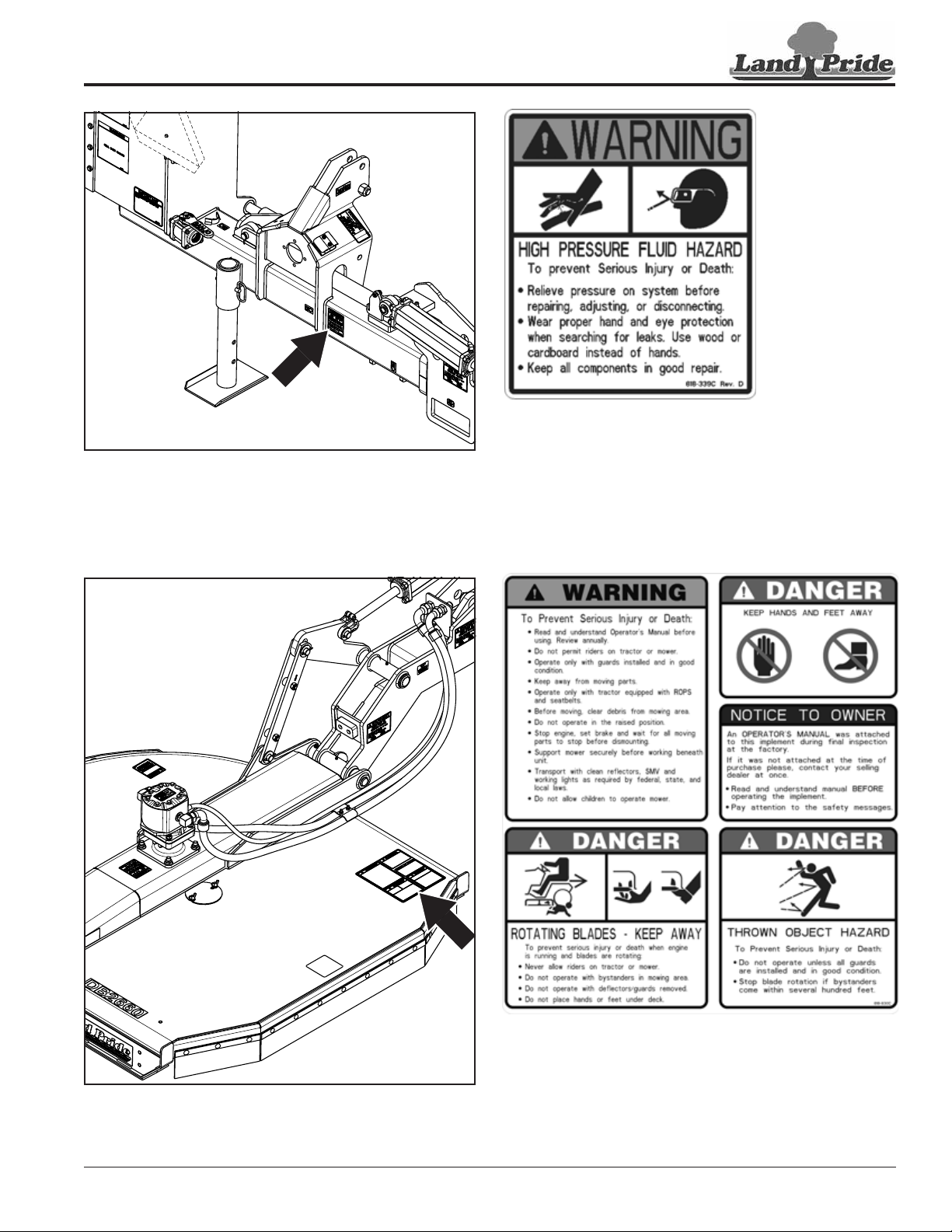
818-830C
Warning/Danger/Notice: Combination Safety Decal
DB2660 & DBM2660 Ditch Bank Rotary Cutter 316-317M
7

Important Safety Information
37250
Table of Contents
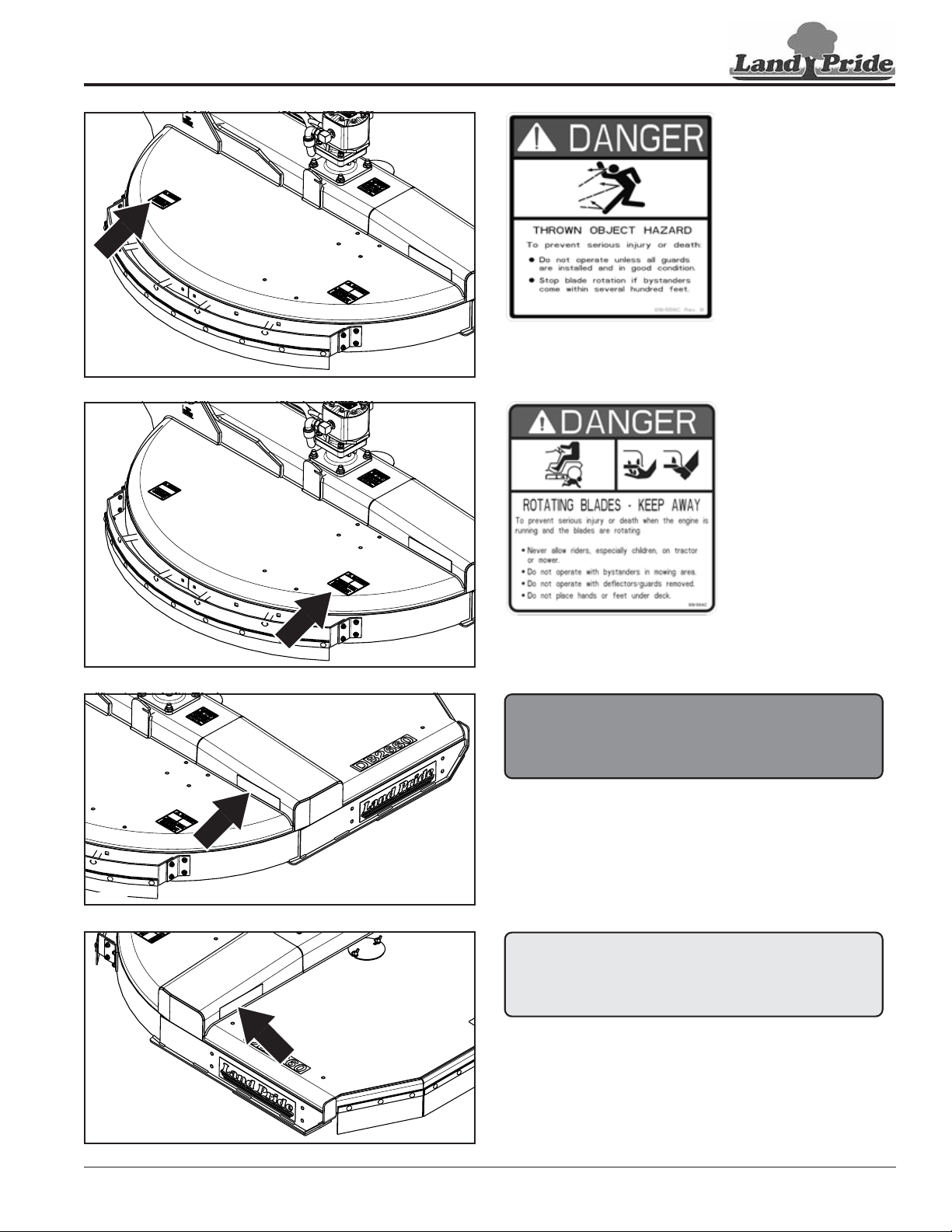
818-555C
Danger: Rotating Blades Keep Away
37250
37250
818-339C
Warning: High Pressure Fluid Hazard
818-045C
Warning: Pinch Point Hazard (4-Places)
37251
8
11/6/18DB2660 & DBM2660 Ditch Bank Rotary Cutter 316-317M
Important Safety Information
37251
Table of Contents
818-556C
Danger: Thrown Object Hazard
37251
37251
818-564C
Danger: Keep Away Rotating Blade Hazard
838-614C
2" x 9" Red Reflector
838-615C
2" x 9" Amber Reflector
37250
11/6/18
DB2660 & DBM2660 Ditch Bank Rotary Cutter 316-317M
9

Important Safety Information
Table of Contents
37334
818-552C
Danger: Rotating Driveline
37334
818-564C
Danger: Guard Missing
10
11/6/18DB2660 & DBM2660 Ditch Bank Rotary Cutter 316-317M

Table of Contents
Introduction
Introduction
Land Pride welcomes you to the growing family of new
product owners. This Ditch Bank Cutter has been
designed with care and built by skilled workers using
quality materials. Proper assembly, maintenance, and
safe operating practices will help you get years of
satisfactory use from this implement.
Application
The DB2660 Hydraulic Ditch Bank Cutter is designed
and built by Land Pride to provide excellent cutting
performance on ditch banks and other sloping areas
adjacent to right-of-ways, lakes, ponds, and streams.
They are designed to work equally as well in and around
areas of restricted access such as guardrails, low
overhanging branches, tree limbs, and hedges. These
units perform extremely well in tall grass cutting
applications and will easily cut through standing brush up
to one inch in diameter. Optional gauge wheels are also
available for customers who want to maintain a constant
cutting height with minimal control lever manipulation.
The DB(M)2660 cutter is designed for tractors in the 75
minimum hp range with a minimum weight of 7,000 lbs.
This cutter will fit Cat. ll 3-point hitches, or it will fit Cat.ll or
Cat. lll quick hitches.
The hydraulic drive requires 540 or 1000 rpm input power
take-off speed. Two duplex hydraulic outlets are required
on the tractor to operate the cutter’s extension arm
cylinder and deck pivot cylinder.
See “Specifications & Capacities” on page 46 and
“Features & Benefits” on page 48 for additional
information and performance enhancing options.
NOTE: A special point of information that the
operator should be aware of before continuing.
Owner Assistance
The dealer should complete the Online Warranty
Registration at the time of purchase. This information is
necessary to provide you with quality customer service.
The parts on your Ditch Bank Cutter have been specially
designed by Land Pride and should only be replaced with
genuine Land Pride parts. Contact a Land Pride dealer if
customer service or repair parts are required. Your Land
Pride dealer has trained personnel, repair parts, and
equipment needed to service the implement.
Serial Number
For quick reference and prompt service, record model
and serial number on the inside cover page and again on
the warranty page. Always provide model number and
serial number when ordering parts and in all
correspondences with your Land Pride dealer. For
location of your serial number plate, see Figure 1.
37349
Using This Manual
This Operator’s Manual is designed to help familiarize
•
you with safety, assembly, operation, adjustments,
troubleshooting, and maintenance. Read this manual
and follow the recommendations to help ensure safe
and efficient operation.
• The information contained within this manual was
current at the time of printing. Some parts may change
slightly to assure you of the best performance.
• To order a new Operator’s or Parts Manual, contact
your authorized dealer. Manuals can also be
downloaded, free-of-charge, from our website at
www.landpride.com
Terminology
“Right” or “Left” as used in this manual is determined by
facing forward in the direction the machine will operate
while in use unless otherwise stated.
Definitions
IMPORTANT: A special point of information related
to the following topic. Land Pride’s intention is this
information must be read & noted before continuing.
Serial Number Plate Location
Figure 1
Further Assistance
Your dealer wants you to be satisfied with your new Ditch
Bank Cutter. If for any reason you do not understand any
part of this manual or are not satisfied with the service
received, the following actions are suggested:
1. Discuss any problems you have with your implement
with your dealership service personnel so they can
address the problem.
2. If you are still not satisfied, seek out the owner or
general manager of the dealership, explain the
problem, and request assistance.
3. For further assistance write to:
Land Pride Service Department
1525 East North Street
P.O. Box 5060
Salina, Ks. 67402-5060
E-mail address
lpservicedept@landpride.com
11/6/18
DB2660 & DBM2660 Ditch Bank Rotary Cutter 316-317M
11

Table of Contents
Section 1: Assembly & Set-up
Section 1: Assembly & Set-up
Tractor Requirements
Tractor horsepower must be capable of controlling the
Ditch Bank Cutter under all operating conditions. Smaller
tractors must not be used.
Horsepower rating . . . . . . . . . . . . . . . 75 minimum hp
3-Point hitch . .Cat. ll std., Cat ll or Cat. lll Quick hitch
See also “3-Point Hitch” below.
Rear power take-off speed:. . . . . . . . 540 or 1000 rpm
Power take-off shaft type: . . . . . . . . . . . . . . . . . . . . . .
540 rpm. . . . . . . . . . . . . . . . . . . . . . 1 3/8”-6 spline
1000 rpm. . . . . . . . . . . . . . . . . . . . .1 3/8"-21 spline
Number of duplex outlets
Extension arm cylinder . . . . . . . . . . . . . . . . . . . . . 1
Deck pivot cylinder . . . . . . . . . . . . . . . . . . . . . . . . 1
See also “Hydraulic Outlets” below.
Tractor Weight
Minimum weight . . . . . . . . . . . . . . . . . . . . 7,000 lbs
See also “Weight” below.
Minimum outside rear wheel base . . . . . . . . . . . . .74"
See also “Wheel Base” on this page.
3-Point Hitch
A 3-point Category II or Category III hitch is required. The
Cat. ll hitch is quick hitch adaptable. A quick hitch must
be used with Cat. lll hitch. The lower 3-point arms of the
3-point hitch must be stabilized to prevent side-to-side
movement. Most tractors have sway blocks or adjustable
chains for this purpose.
It is best to add auxiliary weights to the left rear tractor
wheel. In addition, up to eight 100 lb. suitcase type
weights can be added to the optional weight hanger on
the hydraulic reservoir. However, adding weights to the
reservoir can lighten the tractor’s front. Additional
weights may need to be added to the front of the tractor.
Wheel Base
Refer to Figure 1-1:
Rear wheel base must meet minimum requirements
when measured from outside face to outside face of rear
tractor tires. Smaller wheel bases must not be used.
Tractors equipped with dual wheels will need the outside
right rear wheel removed.
7,000 LBs MIN.
Hydraulic Outlets
Control lever for deck pivot cylinder must be capable of
infinite variable flow control (turtle/rabbit control) with
self-cancel detent without gauge wheels and float detent
with gauge wheels.
Weight
!
WARNING
To avoid serious injury or death:
Lightweight tractors with rear attached implements may need
weights added to the front to maintain steering control.
Consult your tractor Operator’s Manual to determine proper
weight requirements and maximum weight limitations.
IMPORTANT: An extended extension arm will pull
the tractor’s front to the right. When necessary, add
weight to the tractor front to stabilize it. Consult your
tractor’s manual for allowable added weights.
IMPORTANT: The tractor’s right rear wheel should
be pressurized to the manufactures highest
recommended air pressure.
Minimum: Tractor weight must be sufficient to control the
Ditch Bank Cutter under all operating conditions. Tractors
that do not meet the absolute minimum weight listed
above must not be used.
12250
Minimum Tractor Wheel Base and Weight
Figure 1-1
Protective Equipment Requirements
Refer to Figure 1-1:
!
DANGER
To avoid serious injury or death:
Always use a tractor equipped with protective equipment
designed to shield operator from thrown objects and protect
operator from tractor rollover. Always fasten seat belt snugly
and securely when operating the Ditch Bank Cutter. Operating
the Ditch Bank Cutter without proper protective equipment
can result in bodily injury or death.
The tractor MUST be equipped with protective equipment
designed to shield the operator from thrown objects and
tractor rollover. An enclosed tractor cab with a Roll Over
Protective Structure (ROPS) may qualify. See the
tractor’s manual to determine if it qualifies.
Tractors with only a ROPS must have a protective shield
added to the right-hand fender. A universal operator
protective shield is available from Land Pride. Refer to
“Protective Shield (Accessory)” on page 24 for
additional information and installation.
12
11/6/18DB2660 & DBM2660 Ditch Bank Rotary Cutter 316-317M

Section 1: Assembly & Set-up
Table of Contents
It is also recommended that a protective shield or screen
be added to the right-hand side of the tractor engine
cowling and radiator. This will help protect the tractor’s
finish and radiator against thrown objects.
Dealer Preparations
This cutter has been assembled at the factory. However,
some preparations will be necessary to attach the cutter
to the customer’s tractor.
• Make certain the intended tractor conforms to the
“Tractor Requirements” on page 12.
• Review and check off “Pre-Assembly Checklist”
below before proceeding.
Pre-Assembly Checklist
Check
Cat. ll & Cat. lll quick hitch hook-ups will use upper center bolt
and bushing supplied with cutter. An upper hitch pin must be
supplied by customer when making a 3-point Cat II hook-up. If
customer does not have a hitch pin, one can be purchased from
Land Pride. See hitch pin part number and description below.
805-079C - Upper Hitch Pin Cat II (1" dia. x 3 3/8" usable)
Before operating this unit, 80-90 EP Gear Lube must be added
to the speed increaser as indicated in the “Maintenance &
Lubrication” section for “Speed Increaser” on page 42 of this
manual.
35 Gallons of hydraulic fluid is needed for the hydraulic
reservoir. Use high quality mineral based hydraulic fluid such as
Mobilfluid 424 with a viscosity rating of 10W-30.
Additional hydraulic fluid (approx 2 gallons) may be needed for
the tractor reservoir.
Miscellaneous assembly tools: hammer, tape measure,
assortment of wrenches and sockets, and spirit level.
Have a forklift or hoist with properly sized chains and safety
stands on hand capable of lifting 2500 lbs.
Auxiliary tractor weights (depending on tractor size). See
“Tractor Requirements” on page 12.
A minimum of two people available during assembly.
Be sure parts get used in the correct location. Use Parts
Manual to identify location of pins, bolts, and other parts that
you are unsure of their location. By double checking, you will
lessen the chance of using a bolt or pin incorrectly that may be
needed later.
Make sure working parts move freely, bolts are tight & cotter
pins are spread.
Make sure all grease fittings are in place and lubricated.
Make sure all safety decals are legible and undamaged. Red
and amber reflectors are correctly located and visible when
machine is in transport position.
Driveline and loose parts bag/box shipped with the cutter are
present.
Unloading & Parking The Cutter
Refer to Figure 1-2 on page 14:
1. Check transport safety chain (#1). It must be secured
in deck hook (#6) with zip tie (#19) before moving
cutter or working around the unit.
2. Use a fork lift capable of lifting 2500 lbs to lift the
cutter. Insert right fork through slot (#4) in extension
arm and left fork under mainframe (#3) as illustrated
with arrows.
3. Lift cutter from the shipping trailer and transport it to
your work area or storage location.
4. Park fork lift with Ditch Bank Cutter on level hard
ground. Lower cutter until supported on parking
stand (#2) and shipping block (#16).
5. Remove fork lift from under the cutter if storing cutter
without setting it up for tractor hook-up. Do not
remove fork lift if hooking-up cutter to a tractor.
Preparing For Tractor Hook-up
The Ditch Bank Cutter is shipped with the deck folded up
and hydraulic reservoir empty of fluid. The reservoir will
need to be filled with fluid and deck rotated down
before cutter can be hooked-up to a tractor.
Fill Hydraulic Reservoir With Fluid
1. If fork lift is still under the cutter after unloading and
parking the cutter, turn off ignition switch and remove
switch key before dismounting unit to fill hydraulic
reservoir.
NOTE: The hydraulic reservoir can be filled without
the use of the fork lift if the Ditch Bank Cutter has
been properly parked for storage after unloading.
IMPORTANT: Any high quality mineral based
hydraulic fluid such as Mobilfluid 424 with a viscosity
rating of 10W-30 is acceptable. For alternate fluids,
search on the web for “Mobilfluid 424" or go to
www.mobil.com.
2. Remove fill cap (#15) and add 35 gallons of Mobilfluid
424 to the hydraulic reservoir. Use care to ensure
that dust or other foreign particles do not
contaminate the fluid.
Check Hose Loops
Refer to Figure 1-2 on page 14:
IMPORTANT: Hoses (#14) should loop up as shown
and tilt slightly to the back to keep hoses from falling
forward into the tractor tires. They also should be
zipped tied together in three locations as shown.
1. Check hoses (#14) to make sure they loop up as
shown and tilt back at the top.
2. If needed, loosen hoses at bulk head (#11) and tilt top
of hose loops (#14) slightly back. Hold loops in this
position and re-tighten hoses at the bulk head.
3. If additional movement is needed, loosen hose
clamp (#8) and tilt hose loops slightly back. Hold
loops in this position and re-tighten hose clamp bolt.
4. Check hose loops to make sure they are tied together
with zip ties (#17) in the three locations shown. If not,
add zip ties to the hoses as shown.
11/6/18
DB2660 & DBM2660 Ditch Bank Rotary Cutter 316-317M
13
 Loading...