

Land Pride BH3512 User Manual

Table of Contents
Backhoes
BH3512
20555
340-131M
Operator’s Manual
Read the Operator’s manual entirely. When
you see this symbol, the subsequent
instructions and warningsare serious - follow
!
without exception. Your life and the lives of
others depend on it!
© Copyright 2008 Printed
Cover photo may show optional equipment not supplied
7/14/08
with standard unit.

Table of Contents
Table of Contents
Important Safety Information . . . . . . . . . .1
Safety at All Times . . . . . . . . . . . . . . . . . . . . . . . . 1
Look For The Safety Alert Symbol . . . . . . . . . . . . 1
Safety Labels . . . . . . . . . . . . . . . . . . . . . . . . . . . . 4
Introduction . . . . . . . . . . . . . . . . . . . . . . . . 6
Application . . . . . . . . . . . . . . . . . . . . . . . . . . . . . . 6
Using This Manual . . . . . . . . . . . . . . . . . . . . . . . . 6
Terminology . . . . . . . . . . . . . . . . . . . . . . . . . . . 6
Definitions . . . . . . . . . . . . . . . . . . . . . . . . . . . . 6
Owner Assistance . . . . . . . . . . . . . . . . . . . . . . . . . 6
Serial Number Plate . . . . . . . . . . . . . . . . . . . . . 6
Further Assistance . . . . . . . . . . . . . . . . . . . . . . 6
Backhoe Operation, Maintenance & Safety Tips . . 7
Section 1: Assembly and Set-Up . . . . . . . 8
Tractor Requirements . . . . . . . . . . . . . . . . . . . . . . 8
Hydraulic System Requirements . . . . . . . . . . . . . . 8
Open Center System . . . . . . . . . . . . . . . . . . . . . . . 8
Closed Center System . . . . . . . . . . . . . . . . . . . . . 8
Power Beyond Closed Center Kit
Part No. 340-084A . . . . . . . . . . . . . . . . . . . . . . 8
Power Beyond Hydraulic System . . . . . . . . . . . 9
Power Beyond Closed Center Kit
Part No. 340-084A . . . . . . . . . . . . . . . . . . . . . . 9
Choose the Appropriate Hosing. . . . . . . . . . . . . . . 9
Independent P.T.O.
Hydraulic Pump System . . . . . . . . . . . . . . . . . . 9
Testing Procedure for
Hydraulic Circuits . . . . . . . . . . . . . . . . . . . . . . . . 11
Testing Open Center System . . . . . . . . . . . . . . . 11
Checking a Single Circuit . . . . . . . . . . . . . . . . 11
Checking the Cylinders . . . . . . . . . . . . . . . . . . 12
Return Hose: . . . . . . . . . . . . . . . . . . . . . . . . . 12
Testing Closed Center System . . . . . . . . . . . . . . 12
Checking a Single Circuit . . . . . . . . . . . . . . . . 12
Checking the Pump . . . . . . . . . . . . . . . . . . . . 12
Checking The Cylinders . . . . . . . . . . . . . . . . . 12
Using Tractor Hydraulics All Tractors . . . . . . . . . 13
Using Tractor Hydraulics John Deere . . . . . . . . . 13
Mounting The Backhoe . . . . . . . . . . . . . . . . . . . . 13
Description of Major Backhoe Parts . . . . . . . . 13
Bucket Installation . . . . . . . . . . . . . . . . . . . . . 16
Locking Bar Installation (Optional) . . . . . . . . . 16
Seat Assembly . . . . . . . . . . . . . . . . . . . . . . . . 16
Land Pride
Section 2: Operating Instructions . . . . . . 17
Preparing For Operation . . . . . . . . . . . . . . . . . . . 17
Preparing The Backhoe . . . . . . . . . . . . . . . . . 17
Preparing The Tractor . . . . . . . . . . . . . . . . . . . 17
Operating The Backhoe . . . . . . . . . . . . . . . . . . . . 17
Transporting The Backhoe . . . . . . . . . . . . . . . . . 17
Control Functions . . . . . . . . . . . . . . . . . . . . . . . . 18
Stabilizers . . . . . . . . . . . . . . . . . . . . . . . . . . . . 18
Boom . . . . . . . . . . . . . . . . . . . . . . . . . . . . . . . 18
Dipper Stick And Bucket . . . . . . . . . . . . . . . . . 18
Digging Suggestions . . . . . . . . . . . . . . . . . . . . . . 19
Digging at the Correct Angle . . . . . . . . . . . . . . 19
Section 3: Maintenance and Lubrication 21
Maintenance . . . . . . . . . . . . . . . . . . . . . . . . . . . . 21
Storage . . . . . . . . . . . . . . . . . . . . . . . . . . . . . . . . 21
Bucket Tooth Replacement . . . . . . . . . . . . . . . . . 21
Lubrication . . . . . . . . . . . . . . . . . . . . . . . . . . . . . . 22
Bucket Pivot . . . . . . . . . . . . . . . . . . . . . . . . . . 22
Bucket Cylinder Base End . . . . . . . . . . . . . . . 22
Dipper Stick Pivots . . . . . . . . . . . . . . . . . . . . . 22
Boom Cylinder Rod End . . . . . . . . . . . . . . . . . 23
Boom Pivot . . . . . . . . . . . . . . . . . . . . . . . . . . . 23
Boom Cylinder Base End . . . . . . . . . . . . . . . . 23
Stabilizer Arms . . . . . . . . . . . . . . . . . . . . . . . . 24
Boom Swing Cylinder Rod End . . . . . . . . . . . . 24
Boom Swing Cylinder Base End . . . . . . . . . . . 24
Section 4: Specifications & Capacities . 25
Section 5: Features and Benefits . . . . . . 26
Section 6: Troubleshooting . . . . . . . . . . . 27
Section 7: Appendix . . . . . . . . . . . . . . . . 29
Torque Values Chart . . . . . . . . . . . . . . . . . . . . . . 29
Notes . . . . . . . . . . . . . . . . . . . . . . . . . . . . . . . . . . 30
Warranty . . . . . . . . . . . . . . . . . . . . . . . . . . . . . . . 31
© Copyright 2008 All rights Reserved
Land Pride provides this publication “as is” without warrantyof any kind, either expressedor implied. While every precaution has been taken in the preparation of this manual, Land
Pride assumes no responsibility for errors or omissions. Neither is anyliability assumed for damages resulting from the use of theinformation contained herein. Land Pride reserves
the right to revise and improve its products as it sees fit. This publication describes thestate of this product at thetime of its publication, and may not reflect theproduct in the future.
Land Pride is a registered trademark.
All other brands and product names are trademarks or registered trademarks of their respective holders.
Printed in the United States of America.
BH3512 Backhoes 340-131M
7/14/08

Land Pride
▲
Table of Contents
Important Safety Information
Important Safety Information
These are common practices that may or may not be applicable to the products described in
this manual.
Safety at All Times
Thoroughly read and understand
the instructions given in this
manual before operation. Refer to
the “Safety Label” section, read
all instructions noted on them.
Do not allow anyone to operate
this equipment who has not fully
read and comprehended this
manual and who has not been
properly trained in the safe
operation of the equipment.
▲ Operator should be familiar with
all functions of the unit.
▲ Operate implement from the
driver’s seat only.
▲ Make sure all guards and shields
are in place and secured before
operating the implement.
▲ Do not leave tractor or implement
unattended with engine running.
▲ Dismounting from a moving
tractor could cause serious injury
or death.
▲ Do not stand between the tractor
and implement during hitching.
▲ Keep hands, feet, and clothing
away from power-driven parts.
▲ Wear snug fitting clothing to avoid
entanglement with moving parts.
▲ Watch out for wires, trees, etc.,
when raising implement. Make
sure all persons are clear of
working area.
▲ Turning tractor too tight may
cause implement to ride up on
wheels. This could result in injury
or equipment damage.
Look For The Safety Alert Symbol
The SAFETY ALERT SYMBOL indicates there is a
potential hazard to personal safety involved and extra
safety precaution must be taken. When you see this
symbol, be alert and carefully read the message that
follows it. In addition to design and configuration of
!
Be Aware of
Signal Words
A Signal word designates a degree or
level of hazard seriousness. The
signal words are:
!
DANGER
Indicates an imminently hazardous
situation which, if not avoided, will
result in death or serious injury. This
signal word is limited to the most
extreme situations, typically for
machine components that, for
functional purposes, cannot be
guarded.
For Your Protection
▲ Thoroughly read and understand
the “Safety Label” section, read all
instructions noted on them.
equipment, hazard control and accident prevention
are dependent upon the awareness, concern,
prudence and proper training of personnel involvedin
the operation, transport, maintenance and storage of
equipment.
!
WARNING
Indicates a potentially hazardous
situation which, if not avoided, could
result in death or serious injury, and
includes hazards that are exposed
when guards are removed. It may also
be used to alert against unsafe
practices.
!
CAUTION
Indicates a potentially hazardous
situation which, if not avoided, may
result in minor or moderate injury. It
may also be used to alert against
unsafe practices.
Shutdown and Storage
▲ Lower machine to ground, put
tractor in park, turn off engine, and
remove the key.
▲ Detach and store implements in a
area where children normally do
not play. Secure implement by
using blocks and supports.
7/14/08
OFF
REMO
VE
BH3512 Backhoes 340-131M
1
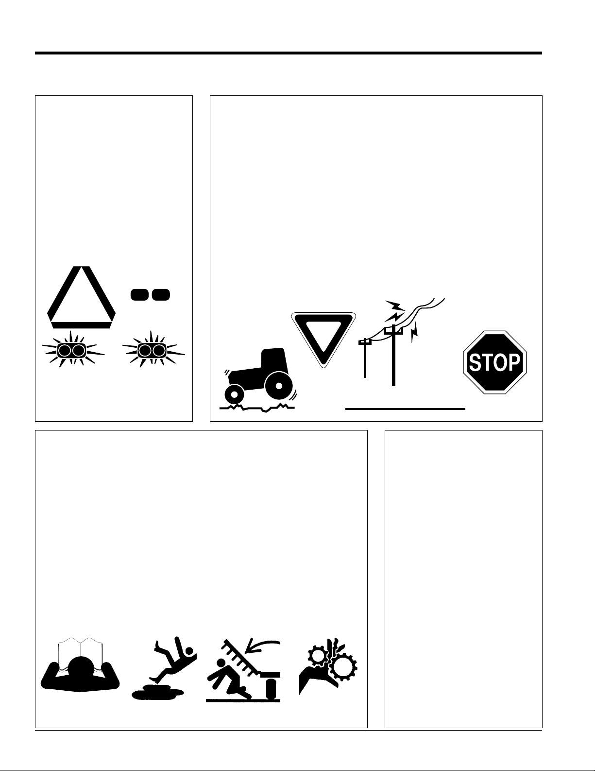
Table of Contents
Land Pride
Important Safety Information
These are common practices that may or may not be applicable to the products described in
this manual.
Use Safety
Lights and Devices
▲ Slow moving tractors, self-
propelled equipment, and towed
implements can create a hazard
when drivenon publicroads. They
are difficult to see, especially at
night.
▲ Flashing warning lights and turn
signals are recommended
whenever driving on public roads.
Transport
Machinery Safely
▲ Comply with state and local laws.
▲ Maximum transport speed for
implement is 20 mph. DO NOT
EXCEED.Never travel at a speed
which does not allow adequate
control of steering and stopping.
Some rough terrain require a
slower speed.
▲ Sudden braking can cause a
towed load to swerve and upset.
Reduce speed if towed load is not
equipped with brakes.
▲ Use the following maximum
speed - tow load weight ratios as
a guideline:
20 mph when weight is less
than or equal to the weight of
tractor.
10 mph when weight is double
the weight of tractor.
IMPORTANT: Do not tow a load that
is more than double the weight of
tractor.
Transporting the Loader
and Attachment
▲ Always drive up the ramp with
heavy end uphill. Engage parking
brake.
▲ Secure loader and attachments
using tiedowns and chains. Use
towing vehicle and trailer of
adequate capacity.
Practice Safe Maintenance
▲ Understand procedure before
doing work. Use proper tools and
equipment, refer to Operator’s
Manual for additional information.
▲ Work in a clean dry area.
▲ Lower the implement to the
ground, put tractor in park, turn off
engine, and remove key before
performing maintenance.
▲ Allow implement to cool
completely.
▲ Do not grease or oil implement
while it is in operation.
▲ Inspect all parts. Make sure parts
are in good condition & installed
properly.
▲ Remove buildup of grease, oil or
debris.
▲ Remove all tools and unused
parts from implement before
operation.
Tractors With Cabs
Tractors Equipped With
ROPS
▲ There should be sufficient
clearance for the operator when
mounted to a tractor with a cab or
that is equipped with ROPS.
▲ The ROPS may need to be
extended or flipped around to
obtain sufficient clearance.
BH3512 Backhoes 340-131M
2
7/14/08
Land Pride
Table of Contents
Important Safety Information
These are common practices that may or may not be applicable to the products described in
this manual.
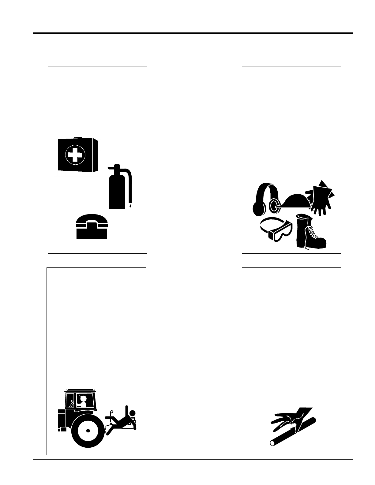
Prepare for Emergencies
▲ Be prepared if a fire starts.
▲ Keep a first aid kit and fire
extinguisher handy.
▲ Keep emergency numbers for
doctor, ambulance, hospital and
fire department near phone.
911
Wear
Protective Equipment
▲ Protective clothing and equipment
should be worn.
▲ Wear clothing and equipment
appropriate for the job. Avoid
loose fitting clothing.
▲ Prolonged exposureto loud noise
can cause hearing impairment or
hearing loss. Wear suitable
hearing protection such as
earmuffs or earplugs.
▲ Operating equipment safely
requires the full attention of the
operator. Avoid wearing radio
headphones while operating
machinery.
Keep Riders
Off Machinery
▲ Riders obstruct the operator’s
view, they could be struck by
foreign objects or thrown from the
machine.
▲ Never allow children to operate
equipment.
Avoid High
Pressure Fluids Hazard
▲ Escaping fluid under pressure can
penetratethe skincausing serious
injury.
▲ Avoid the hazard by relieving
pressure before disconnecting
hydraulic lines.
▲ Use a piece of paper or
cardboard, NOTBODYPARTS, to
check for suspected leaks.
▲ Wear protective glovesand safety
glasses or goggles when working
with hydraulic systems.
▲ If an accident occurs, see a
doctor immediately. Any fluid
injected into the skin must be
surgically removed within a few
hours or gangrene may result.
7/14/08
BH3512 Backhoes 340-131M
3
Important Safety Information
Table of Contents
Land Pride
Safety Labels
Your backhoe comes equipped with all safety labels in place.
They were designed to help you safely operate your implement.
Read and follow their directions.
1. Keep all safety labels clean and legible.
2. Replace all damaged or missing labels. To order new
labels go to your nearest Land Pride dealer.
3. Some new equipment installed during repair requires
safety labels to be affixed to the replaced component as
specified by Land Pride. When ordering new components
19364
make sure the correct safety labels are included in the
request.
4. Refer to this section for proper label placement.
To install new labels:
a. Clean the area the label is to be placed.
b. Spray soapy water on the surface where the label is to
be placed.
c. Peel backing from label. Press firmly onto the surface.
d. Squeeze out air bubbles with the edge of a credit card.
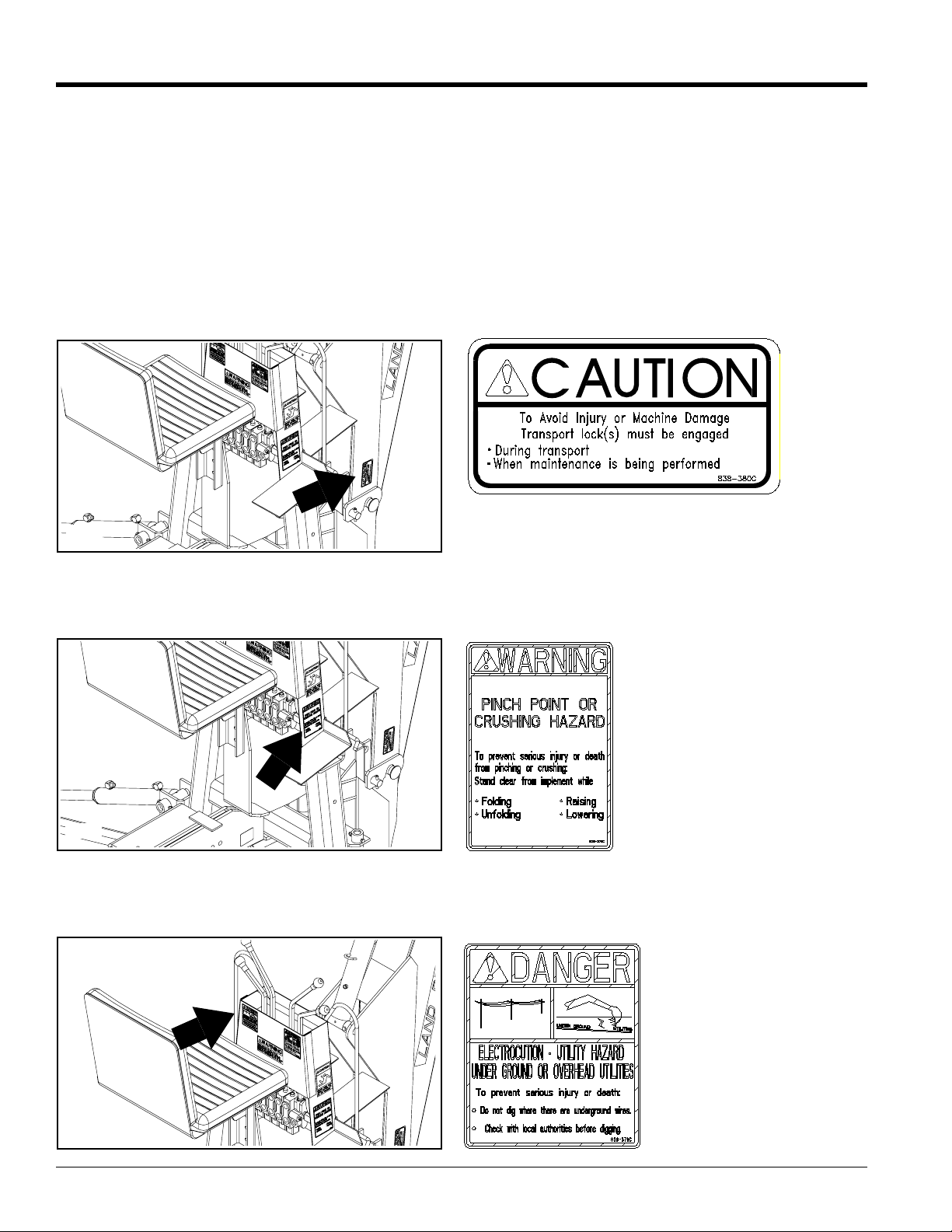
838-380C
Caution: Lock For Transport
19366
19366
BH3512 Backhoes 340-131M
4
838-378C
Warning: Pinch or Crush Hazard
838-379C
Danger: Overhead/
Underground Utilities
7/14/08
Land Pride
Important Safety Information
Table of Contents
19366
19366
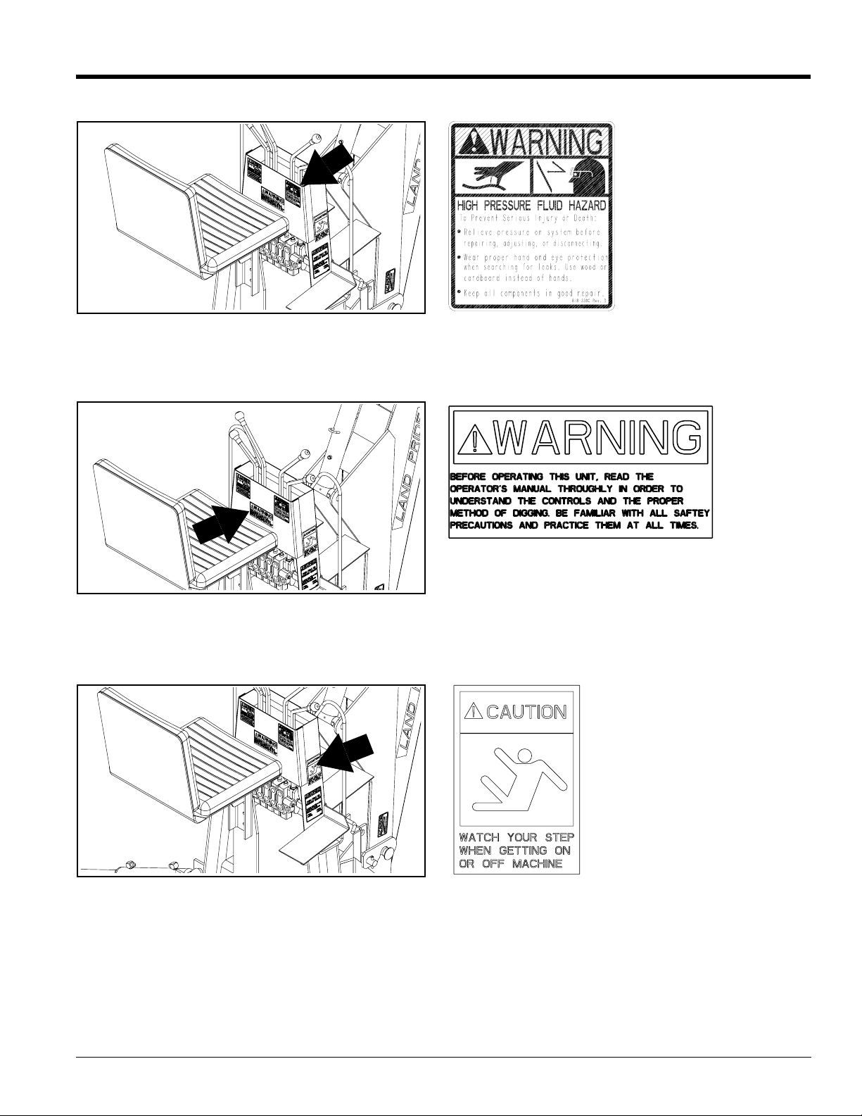
818-339C
Warning: High Pressure
839-933C
Warning: General
19366
7/14/08
839-932C
Caution: Watch your step
BH3512 Backhoes 340-131M
5
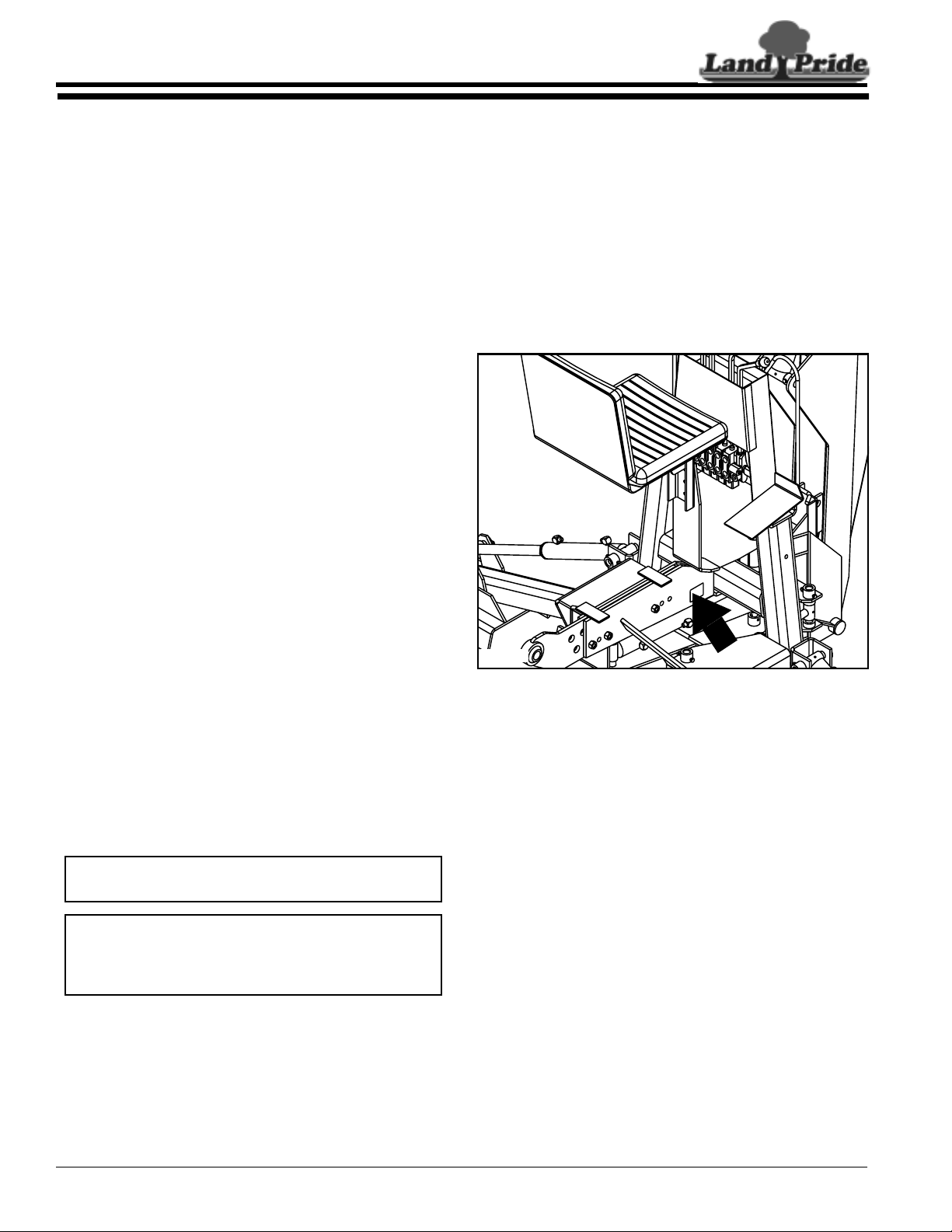
Table of Contents
Introduction
Introduction
Land Pride welcomes you to the growing family of new
product owners.
This Backhoe has been designed with care and built by
skilledworkers usingquality materials.Proper assembly,
maintenance, and safe operating practices will help you
get years of satisfactory use from the machine.
Application
TheBH3512 Backhoeis theideal toolfor farms,drainage
ditches, nurseries, golf courses, utilities and cemeteries.
An unobstructed view of the work area, comfortable
positioning of the controls and walk through platform
allow for hours of fatigue free work. Stabilizer legs
provide a stance of 10’ 7" assuring more stability and
safer operational control. Optional rubber shoes can be
added to the stabilizer legs for working on concrete.
Selectedskid steer loader mounting kits areavailable for
added versatility. See “Features and Benefits”,
“Section 6” for additional information.
Land Pride
parts and equipment needed to service the backhoe.
Theparts onyour backhoehave beenspecially designed
and should only be replaced with genuine Land Pride
parts. Therefore, should your backhoe require
replacement parts go to your Land Pride Dealer.
Serial Number Plate
For prompt service always use the serial number and
modelnumber when ordering parts fromyour Land Pride
dealer.Be sureto include yourserial andmodel numbers
incorrespondence also. Referto Figure 1 forthe location
of your serial number plate.
Using This Manual
This Operator’s Manual is designed to help familiarize
•
you with safety, assembly, operation, adjustments,
troubleshooting, and maintenance. Read this manual
and follow the recommendations to help ensure safe
and efficient operation.
• The information contained within this manual was
current at the time of printing. Some parts may change
slightly to assure you of the best performance.
• To order a new Operator’s or Parts Manual contact
your authorized dealer. Manuals can also be
downloaded, free-of-charge from our website at
www.landpride.com or printed from the Land Pride
Service & Support Center by your dealer.
Terminology
“Right” or “Left” as used in this manual is determined by
facing the direction the machine will operate while in use
unless otherwise stated.
Definitions
NOTE: A special point of information that the
operator must be aware of before continuing.
IMPORTANT: A special point of information related
to its preceding topic. Land Pride’s intention is that
this information should be read and noted before
continuing.
Owner Assistance
The Warranty Registration card should be filled out by
the dealer at the time of purchase. This information is
necessary to provide you with quality customer service.
If customer service or repair parts are requiredcontact a
LandPride dealer. Adealer has trainedpersonnel, repair
20556
Serial Number Plate Location
Figure 1
Further Assistance
Your dealer wants you to be satisfied with your new
backhoe. If for any reason you do not understand any
part of this manual or are not satisfied with the service
received, the following actions are suggested:
1. Discuss the matter with your dealership service
manager making sure he is aware of any problems
youmay have and that he has had the opportunity to
assist you.
2. If you are still not satisfied, seek out the owner or
general manager of the dealership, explain the
problem and request assistance.
3. For further assistance write to:
Land Pride Service Department
1525 East North Street
P.O. Box 5060
Salina, Ks. 67402-5060
E-mail address
lpservicedept@landpride.com
BH3512 Backhoes 340-131M
6
7/14/08

Land Pride
Introduction
Table of Contents
Backhoe Operation, Maintenance & Safety Tips
1. Your backhoe must be mounted only on a tractor
equipped with a Category 1 or 2 hitch or Skid Steer
Hitch. Failure to do so may result in serious injury.
2. When servicing the backhoe, make sure all moving
parts are on the ground.
3. To avoid injury from escaping pressurized hydraulic
fluid, move the control levers in all directions before
disconnecting any hoses, steel lines, or couplers.
4. Keep footpads clean to prevent feet from slipping
while mounting backhoe.
5. Do not transport your backhoe with the bucket fully
raised.
6. Besure your tractor hassufficient front end weight to
operate and transport the backhoe.
7. When traveling on highways and roads, be sure the
boom and stabilizers are in the fully raised position
and transport lock is in the transport lock position.
8. When traveling on a road with your backhoe, use
proper safety lights and warning sign. Check local
regulations.
9. When traveling with your backhoe, do not make
sudden starts, stops or turn at high speeds. Do not
exceed safe speed limits on rough ground. Do not
make sudden starts when climbing grades.
10. Always wear protective headgear while operating
backhoe.
11. Be sure to lower the stabilizers to the ground before
operating the backhoe.
12. Lookout for overhead low hanging wires. Do not
touch wires with any part of the backhoe.
13. Do not operate from any position other than the
backhoe’s operator’s seat.
14. Before swinging the backhoe for any reason, make
sure youhaveroom to swing and that allpersons are
clear of the backhoe.
15. Be extra careful when workingon hillsides andclose
to ditches or any place where danger of tipping or
sliding is possible.
16. Do not dig under the stabilizers or backhoe, as a
cave-in could occur.
17. Be sure you are not digging overunderground wiring
or other underground obstr uctions.
18. When digging to either side and close to the tractor,
be extremely careful that the backhoe does not
contact the stabilizers as serious damage could
occur.
19. Do not attempt to raise the tractor off the ground or
movethetractorforwardor backwardusingthe boom
or stabilizers.
20. When leaving the backhoe for any reason, lower the
bucket to the ground for safety.
21. Never leave the backhoe unattended with tractor
engine r unning.
22. To prevent injury during assembly,installation,
operation, adjustment, or removal of the backhoe, it
is recommended that gloves, safety glasses or face
shield, and safety toe shoes be worn.
23. Do not wear loose clothing while operating or
working near the backhoe. Keep hair and clothing
awayfrom all moving parts of the backhoe.
24. Only the operator shouldbe near thebackhoe during
operation. Keep all others a minimum of fifty feet
awayfrom your work area.
25. Keep your work area clear of obstacles at all times.
26. Children should never be permitted to operate the
backhoe.
27. Do not attempt any repairs, maintenance, or
adjustments of your backhoe while it is in operation.
Alwaysturn off yourtractor beforemaking repairs or
adjustments or performing maintenance procedures.
28. When the use of hand tools is required to perform
any part of assembly, installation, removal or
adjustment ofthe backhoe, be sure that the toolsare
designed and recommended by the tool
manufacturer for the specific task in which they are
being used.
29. Keep all bolts and nuts tight. Replace any damaged
or wor n parts such as hydraulic hoses and fittings
immediately. Alwaysuse Land Pride replacement
parts.
30. Perform all maintenance procedures as
recommended.
31. Anytime hoses are disconnectedfrom your backhoe,
cover all open por ts with protective caps or plugs in
order to prevent contamination of the oil supply.
IMPORTANT: Make sure that there is sufficient
clearance forthe operator if the backhoe is mounted
to a tractor with a cab or is equipped with a ROPS.
The ROPS may need to be extended or flipped
around to obtain sufficient clearance.
7/14/08
BH3512 Backhoes 340-131M
7

Section 1: Assembly and Set-Up
Section 1: Assembly and Set-Up
Table of Contents
Land Pride
Tractor Requirements
!
CAUTION!
Your backhoe must be mounted only on a tractor equipped with
a Category 2 and 3 hitch.Failureto do so may result in serious
injury.
NOTE: In order to maintain steering control on your
tractor,ballast may need to be addedto your tractor.
To determine whether or not to add the ballast, refer
to your tractor’s operator manual.
Hydraulic System Requirements
!
CAUTION!
The backhoe valve must be compatible with the hydraulic
system that will power it. Make surethat if you arepowering the
backhoe with an open center hydraulic system, the backhoe is
set for open center operation. If you are using a closed center
hydraulic system, the valve must be set for closed center
operation.If you areusinga powerbeyondsetup, the valve must
be converted for this use. See the appropriate section of this
manual on how to convert your valve. If you do not know how
your valve is currently setup, check with your Land Pride
dealer.
Open Center System
Removecap from the1/2” highpressure hose connected
to the right hand side of backhoe valve. The high
pressure hose may be connected to any high pressure
outlet in the tractor system. A tractor remote hydraulic
valve is usually the preferable source. An oil quick
coupler thatis compatible to the oil coupler on the tractor
valve is permissible.
Thereturn hosemust be connectedso that theoil returns
directly to the tractor oil sump. DO NOT connect the
return hose directly to the tractor remote valve. If the
operator would be reversed. This could result in damage
to the return hose or the backhoe’s hydraulic valve.
!
CAUTION!
The hydraulic valve can be damaged by reverse flow of oil
through the valve, disconnecting the return hose while the
tractor is running, and by using more than 12 GPM of oil flow
while operating. The valve manufacturer will not warrant the
valve when damaged under these circumstances.
Closed Center System
Power Beyond Closed Center Kit Part No. 340-084A
Your backhoe cylinders have been filled with oil at the
factory. The oil in the unitis compatible with most tractor
manufacturers’oil. Do notmove anycontrollevers onthe
unit until after hydraulic connections to the tractor or the
independent hydraulic system have been made.
The Land Pride Backhoe has been designed to be
operated at a flow rate of 8-11 GPM.
Since many tractor systems exceed a flow rate specified
for your backhoe, the flow may have to be adjusted by
throttling the engine RPM down to obtain an acceptable
flow rate. By adjusting the flow rate correctly, you will
prevent sudden shock loads on the cylinders, pins,
hoses seals, etc. This results in a smooth operation and
reduced maintenance costs and down time.
!
CAUTION!
If you are going to use a closed center tractor hydraulic system
to power your Land Pride Backhoe, A Power Beyond and
Closed Center Kit must be purchased from your Land Pride
Dealer, then you must follow carefully the directions below.
Failure to do so may cause extensive damage to your tractor
and/or Land Pride Backhoe.
BH3512 Backhoes 340-131M
8
7/14/08
Land Pride
Section 1: Assembly and Set-Up
Table of Contents
Refer to Figure 1-1:
1. Adjust the Valve Bypass for Closed Center
Conversion only.
a. Removethe covernut (#3) from the valvebypass.
This exposes a socket head screw.
b. Loosen locknut and turn socket head screw in
approximately four complete turns, then tighten
locknut.
c. Replacecover nut. Be sure to replace the washer
with the cover nut as it acts as a gasket.
2. Installing the Closed Center Sleeve.
a. Return hose must be connected to the return
sectionof thevalveat point “A”and withthe other
end to the tractor.
b. Remove elbowat point “B” and install the closed
center sleeve (#1). Use the plug (#2) that was
removed from port “A” to plug the sleeve.
c. Withthe removalof the O-Ringplug from the front
of outlet section of the valve Point “A” and
replace with a 839-768C O-Ring adapter.
Connectreturnline to theadapter andreturn tooil
sump of the tractor.
19516
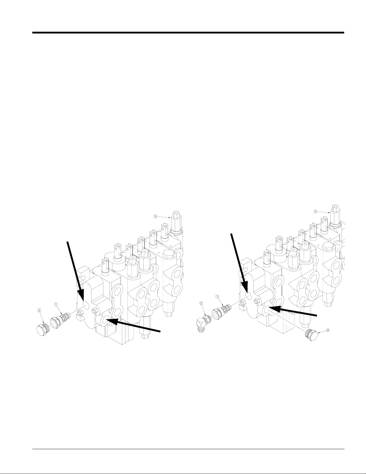
Power Beyond Closed Center Kit Part No. 340-084A
For power beyond applications, a Power Beyond and
Closed Center Kit (Part # 340-084A) must be purchased
from your Land Pride Dealer, then perform the following
steps:
3. Remove return hose and elbow,only if it was
installed at point “B”.
4. Remove plug (#4) from port “A” and install Power
beyondsleeve (#1) in port “B” as shown in Figure 1-
2.
5. Install a #8 O-Ring ell (Part # 839-882C) (#2) into
closedcenter sleeve(#1) opening. This convertsit to
a power beyond sleeve.
6. Install a high pressure hose going to the inlet of
another valve (front loader valve). This hose is not
furnished.
7. If the return hose was installed at Point “B” it must
be relocated and installed at point “A” of the outlet
section. Remove the O’Ring plug and install one
839-768C adapter. Connect the return hose to the
elbowand the other end to the oil sump of the tractor.
B
A
Closed Center Hydraulic Systems
Figure 1-1
This procedure converts the valve to a closed center
operation. If the valve is set for closed center operation,
it maybe converted back to open center by reversing the
above procedure.
Power Beyond Hydraulic System
If you wish to run both a loader and a backhoe from the
same hydraulic system, make your connection as
illustrated in Figure 1-2. Since there are so many
variations for this type of setup, we are showing only a
generalized hosing scheme. If you have any questions
concerning the specifics for your situation, please
contact your dealer before attempting operation.
7/14/08
B
A
19386
Power Beyond Hydraulic Systems
Figure 1-2
Choose the Appropriate Hosing.
Independent P.T.O. Hydraulic Pump System
Install the independent hydraulic system onto the
backhoe according to the following procedures. Refer to
Figure 1-3 and Figure 1-4 for the identification of the
parts. During the assembly, use pipe compound on all
pipe fittings. None is required on the O-Ring fittings.
a. Insert the filter into the SUCTION PORT of the
reservoir.This isthe port thatis located on the left
side of the reservoir.
BH3512 Backhoes 340-131M
9
 Loading...