

Page 1
Table of Contents
All Purpose Seeder
APS1548, APS1560, APS1572 & APS1586
24932
APS1548
APS1586
313-354M
Operator’s Manual
Read the Operator’s manual entirely. When
you see this symbol, the subsequent
!
instructions andwarningsare serious - follow
without exception. Your life and the lives of
others depend on it!
25982
© Copyright 2008 Printed
Cover photo may show optional equipment
not supplied with standard unit.
5/13/08
Page 2

Table of Contents
Table of Contents
Land Pride
Important Safety Information . . . . . . . . . . .1
Safety at All Times . . . . . . . . . . . . . . . . . . . . . . . . . 1
Look For The Safety Alert Symbol . . . . . . . . . . . . .1
Safety Labels . . . . . . . . . . . . . . . . . . . . . . . . . . . . . 4
Introduction . . . . . . . . . . . . . . . . . . . . . . . .6
Application . . . . . . . . . . . . . . . . . . . . . . . . . . . . . . . 6
Using This Manual . . . . . . . . . . . . . . . . . . . . . . . . .6
Terminology . . . . . . . . . . . . . . . . . . . . . . . . . . . 6
Definitions . . . . . . . . . . . . . . . . . . . . . . . . . . . . .6
Owner Assistance . . . . . . . . . . . . . . . . . . . . . . . . . 6
Serial Number Plate . . . . . . . . . . . . . . . . . . . . . 6
Further Assistance . . . . . . . . . . . . . . . . . . . . . .6
Section 1: Assembly & Set-up . . . . . . . . .7
Tractor Requirements . . . . . . . . . . . . . . . . . . . . . .7
Sling Bracket . . . . . . . . . . . . . . . . . . . . . . . . . . . . . 7
Dealer Preparations . . . . . . . . . . . . . . . . . . . . . . . . 7
Pre-Assembly Checklist . . . . . . . . . . . . . . . . . . . . . 7
Mud Scraper Installation (Optional) . . . . . . . . . . . . 7
Front Mud Scrapers . . . . . . . . . . . . . . . . . . . . . 8
Rear Mud Scraper . . . . . . . . . . . . . . . . . . . . . . .8
Special Instructions For Packer Roller . . . . . . . 9
Special Instructions For Spike Roller . . . . . . . 10
Section 2: Operating Instructions . . . . . . 11
Operating Check List . . . . . . . . . . . . . . . . . . . . . . 11
Tractor Hook-up . . . . . . . . . . . . . . . . . . . . . . . . . . 11
Transporting . . . . . . . . . . . . . . . . . . . . . . . . . . . . 11
Filling the Seed Box . . . . . . . . . . . . . . . . . . . . . . . 11
How the Seeder Works . . . . . . . . . . . . . . . . . . . . 12
Operating the Seeder . . . . . . . . . . . . . . . . . . . . . 12
Parking the Seeder . . . . . . . . . . . . . . . . . . . . . . .13
General Operating Instructions . . . . . . . . . . . . . .13
Section 3: Adjustments . . . . . . . . . . . . . .14
Front Roller Angle Adjustment . . . . . . . . . . . . . . .14
Mud Scraper Adjustment (Optional) . . . . . . . . . . .14
Front Mud Scrapers . . . . . . . . . . . . . . . . . . . . .14
Rear Mud Scrapers . . . . . . . . . . . . . . . . . . . . .14
Special Instructions for Spike Rollers . . . . . . .14
Drive Chain Engagement . . . . . . . . . . . . . . . . . . .15
Speed Change Sprocket . . . . . . . . . . . . . . . . . . .16
High Range Set-up . . . . . . . . . . . . . . . . . . . . .16
Low Range Set-up . . . . . . . . . . . . . . . . . . . . . .16
Seeding Adjustments . . . . . . . . . . . . . . . . . . . . . .17
Seed Rate Charts (English) . . . . . . . . . . . . . . . . .18
Seed Rate Charts (Metric) . . . . . . . . . . . . . . . . . .20
Section 4: Maintenance & Lubrication . .22
Maintenance . . . . . . . . . . . . . . . . . . . . . . . . . . . .22
Roller Chains . . . . . . . . . . . . . . . . . . . . . . . . . . . .22
Cleaning and Storing . . . . . . . . . . . . . . . . . . . . . .22
Lubrication Points . . . . . . . . . . . . . . . . . . . . . . . .23
Feed Cup Drive Sprocket Square Bore . . . . . .23
Front Roller Bearings . . . . . . . . . . . . . . . . . . .23
Rear Roller Bearings . . . . . . . . . . . . . . . . . . . .24
Roller Chains . . . . . . . . . . . . . . . . . . . . . . . . . .24
Section 5: Specifications & Capacities . 25
Section 6: Features and Benefits . . . . . .26
Section 7: Troubleshooting . . . . . . . . . .27
Section 8: Appendix . . . . . . . . . . . . . . . .28
© Copyright 2008 All rights Reserved
Land Pride provides this publication “asis” without warranty ofany kind, either expressedor implied. While every precaution has beentaken in the preparationof this manual, Land
Pride assumesno responsibility forerrors oromissions. Neither isany liability assumedfor damagesresulting from theuse of theinformation contained herein.Land Pride reserves
the rightto revise andimprove itsproducts as it sees fit. This publicationdescribes the stateof this productat the time of its publication,and may notreflect the productin the future.
Land Pride isa registered trademark.
All other brands and product names are trademarksor registered trademarks of their respectiveholders.
Printed in the United States of America.
APS1548, APS1560, APS1572 & APS1586 All Purpose Seeder 313-354M
5/13/08
Page 3
Land Pride
▲
Table of Contents
Important Safety Information
Important Safety Information
These are common practices that may or may not be applicable to the products described in
this manual.
Safety at All Times
Thoroughly read and understand
the instructions given in this
manual before operation. Refer to
the “Safety Label” section, read
all instructions noted on them.
Do not allow anyone to operate
this equipment who has not fully
read and comprehended this
manual and who has not been
properly trained in the safe
operation of the equipment.
▲ Operator should be familiar with
all functions of the unit.
▲ Operate implement from the
driver’s seat only.
▲ Make sure all guards and shields
are in place and secured before
operating the implement.
▲ Do not leave tractor or implement
unattended with engine running.
▲ Dismounting from a moving
tractor could cause serious injury
or death.
▲ Do not stand between the tractor
and implement during hitching.
▲ Keep hands, feet, and clothing
away from power-driven parts.
▲ Wear snug fitting clothing to avoid
entanglement with moving parts.
▲ Turning tractor too tight may
cause implement to ride up on
wheels. This could result in injury
or equipment damage.
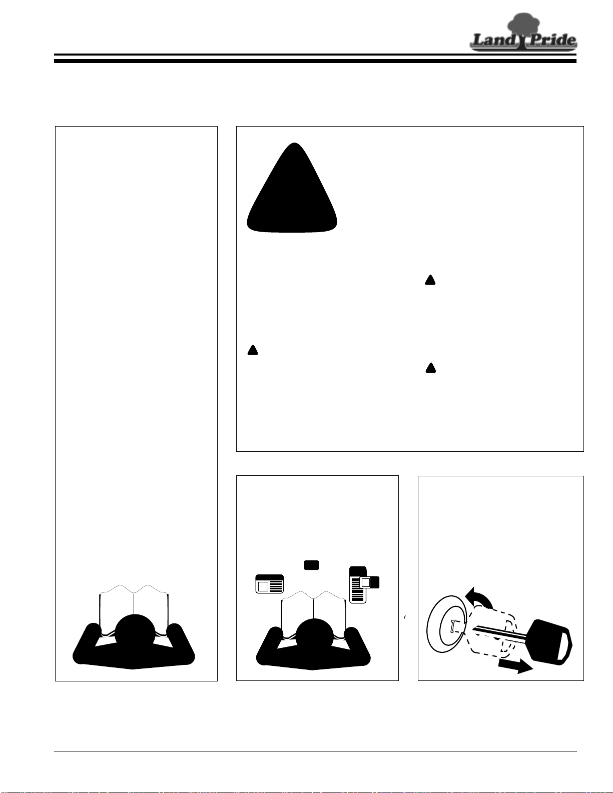
Look For The Safety Alert Symbol
The SAFETY ALERT SYMBOL indicates there is a potential hazard to personal safety involved and extra
safety precaution must be taken. When you see this
symbol, be alert and carefully read the message that
follows it. In addition to design and configuration of
!
Be Aware of
Signal Words
A Signal word designates a degree or
level of hazard seriousness. The
signal words are:
!
DANGER
Indicates an imminently hazardous
situation which, if not avoided, will
result in death or serious injury. This
signal word is limited to the most
extreme situations, typically for
machine components that, for
functional purposes, cannot be
guarded.
For Your Protection
▲ Thoroughly read and understand
the “SafetyLabel”section, read all
instructions noted on them.
equipment, hazard control and accident prevention
are dependent upon the awareness, concern, prudence and proper training of personnel involved in
the operation, transport, maintenance andstorage of
equipment.
!
WARNING
Indicates a potentially hazardous
situation which, if not avoided, could
result in death or serious injury, and
includes hazards that are exposed
when guards are removed. It mayalso
be used to alert against unsafe
practices.
!
CAUTION
Indicates a potentially hazardous
situation which, if not avoided, may
result in minor or moderate injury. It
may also be used to alert against
unsafe practices.
Shutdown and Storage
▲ Lower machine to ground, put
tractor in park, turn off engine, and
remove the key.
▲ Detach and store implements in a
area where children normally do
not play. Secure implement by
using blocks and supports.
5/13/08
OFF
REMO
VE
APS1548, APS1560, APS1572 & APS1586 All Purpose Seeder 313-354M
1
Page 4
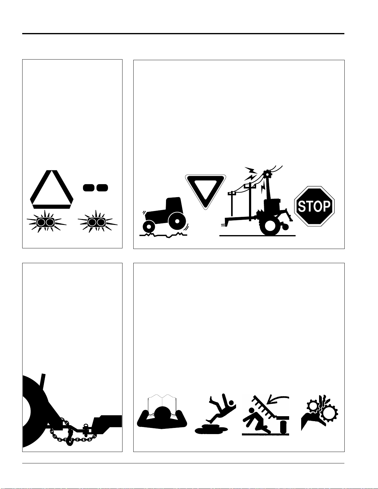
Table of Contents
Land Pride
Important Safety Information
These are common practices that may or may not be applicable to the products described in
this manual.
Use Safety
Lights and Devices
▲ Slow moving tractors, self-
propelled equipment, and towed
implements can create a hazard
whendrivenonpublicroads.They
are difficult to see, especially at
night.
▲ Flashing warning lights and turn
signals are recommended
wheneverdriving on public roads.
Use lights and devices provided
with implement.
Transport
Machinery Safely
▲ Comply with state and local laws.
▲ Maximum transport speed for
implement is 20 mph. DO NOT
EXCEED.Nevertravelat a speed
which does not allow adequate
control of steering and stopping.
Some rough terrain require a
slower speed.
▲ Sudden braking can cause a
towed load to swerve and upset.
Reduce speed if towed load is not
equipped with brakes.
▲ Use the following maximum
speed - tow load weight ratios as
a guideline:
20 mph when weight is less
than or equal to the weight of
tractor.
10 mph when weight is double
the weight of tractor.
▲ IMPORTANT: Do not tow a load
that is more than double the
weight of tractor.
▲
Use A Safety Chain
▲ A safety chain will help control
drawn machinery should it
separate from the tractor
drawbar.
▲ Use a chain with the strength
rating equal to or greater than
the gross weight of the towed
machinery.
▲ Attach the chain to the tractor
drawbar support or other
specified anchor location. Allow
only enough slack in the chain
to permit turning.
▲ Do not use safety chain for
towing.
Practice Safe Maintenance
▲ Understand procedure beforedoing
work. Use proper tools and
equipment, refer to Operator’s
Manual for additional information.
▲ Work in a clean dry area.
▲ Lower the implement to the ground,
put tractor in park, turn off engine,
and remove key before performing
maintenance.
▲ Allow implement to cool completely.
▲ Do not grease or oil implement
while it is in operation.
▲ Inspect all parts. Make sure parts
are in good condition & installed
properly.
▲ Remove buildup of grease, oil or
debris.
▲ Remove all tools and unused
parts from implement before
operation.
APS1548, APS1560, APS1572 & APS1586 All Purpose Seeder 313-354M
2
5/13/08
Page 5
Land Pride
Table of Contents
Important Safety Information
These are common practices that may or may not be applicable to the products described in
this manual.
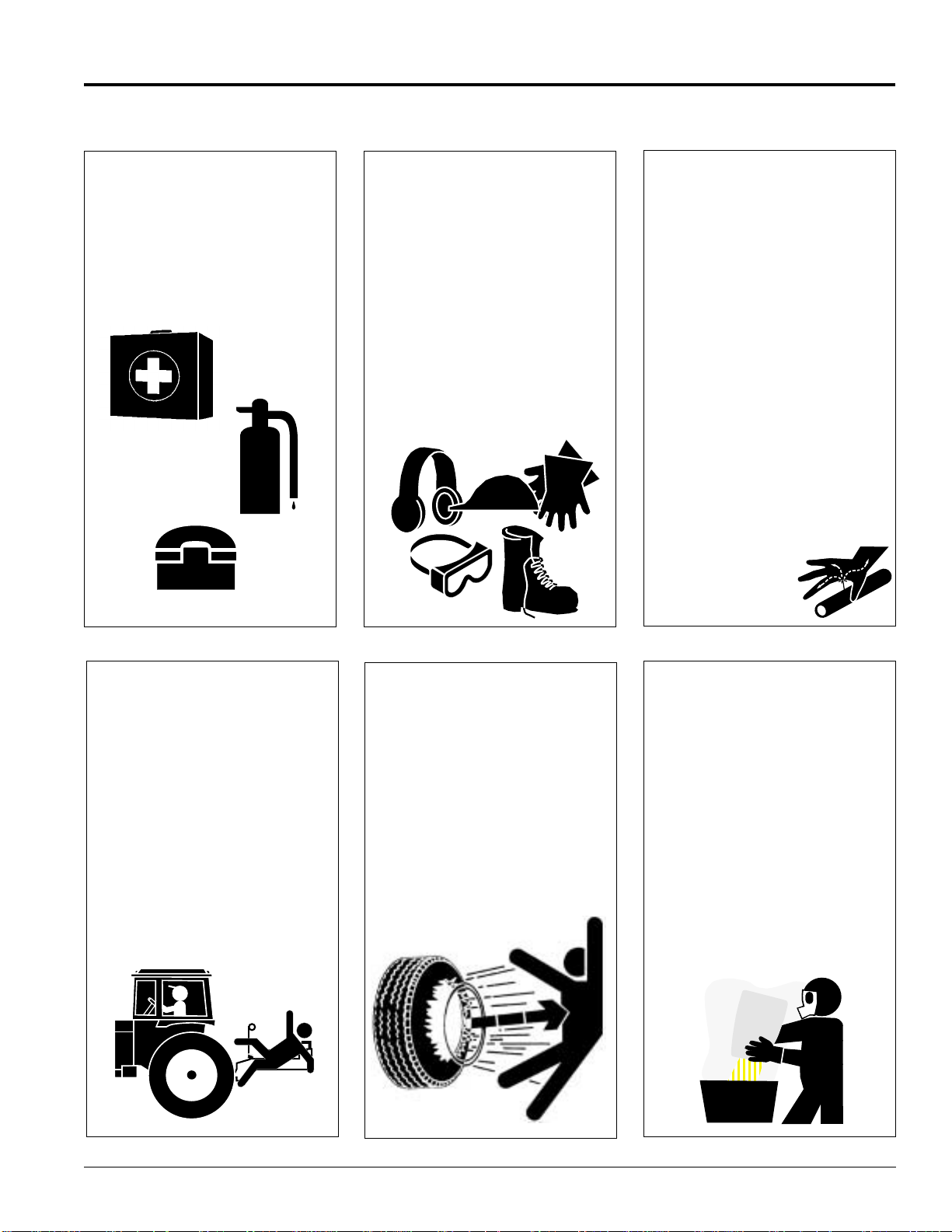
Prepare for Emergencies
▲ Be prepared if a fire starts.
▲ Keep a first aid kit and fire
extinguisher handy.
▲ Keep emergency numbers for
doctor, ambulance, hospital and
fire department near phone.
911
Wear
Protective Equipment
▲ Protectiveclothingandequipment
should be worn.
▲ Wear clothing and equipment
appropriate for the job. Avoid
loose fitting clothing.
▲ Prolonged exposure to loud noise
can cause hearing impairment or
hearing loss. Wear suitable
hearing protection such as
earmuffs or earplugs.
▲ Operating equipment safely
requires the full attention of the
operator. Avoid wearing radio
headphones while operating
machinery.
Avoid High
Pressure Fluids Hazard
▲ Escaping fluid underpressurecan
penetrate the skin causing
serious injury.
▲ Avoid the hazard by relieving
pressure before disconnecting
hydrauliclines or performing work
on the system.
▲ Make sure all hydraulic fluid
connections are tight and all
hydraulic hoses and lines are in
good condition before applying
pressure to the system.
▲ Use a piece of paper or
cardboard, NOT BODY PARTS,to
check for suspected leaks.
▲ Wear protective gloves and safety
glasses or goggles when working
with hydraulic systems.
▲ If an accident occurs, see a
doctor immediately. Any fluid
injected into the skin must be
treated within a few hours or
gangrene may result.
Keep Riders
Off Machinery
▲ Riders obstruct the operator’s
view, they could be struck by
foreign objects or thrown from the
machine.
▲ Never allow children to operate
equipment.
Tire Safety
▲ Tire changing can be dangerous
and should be preformed by
trained personnel using the
correct tools and equipment.
▲ When inflating tires, use a clip-on
chuck and extension hose long
enough to allow you to stand to
one side and NOT in front of or
over the tire assembly. Use a
safety cage if available.
▲ When removing and installing
wheels, use wheel handling
equipment adequate for the
weight involved.
Handle
Chemicals Properly
▲ Protective clothing should be
worn.
▲ Handle all chemicals with care.
▲ Follow instructions on container
label.
▲ Agricultural chemicals can be
dangerous. Improper use can
seriously injure persons, animals,
plants, soil, and property.
▲ Inhaling smoke from any type of
chemical fire is a serious health
hazard.
▲ Store or dispose of unused
chemicals as specified by the
chemical manufacturer.
5/13/08
APS1548, APS1560, APS1572 & APS1586 All Purpose Seeder 313-354M
3
Page 6
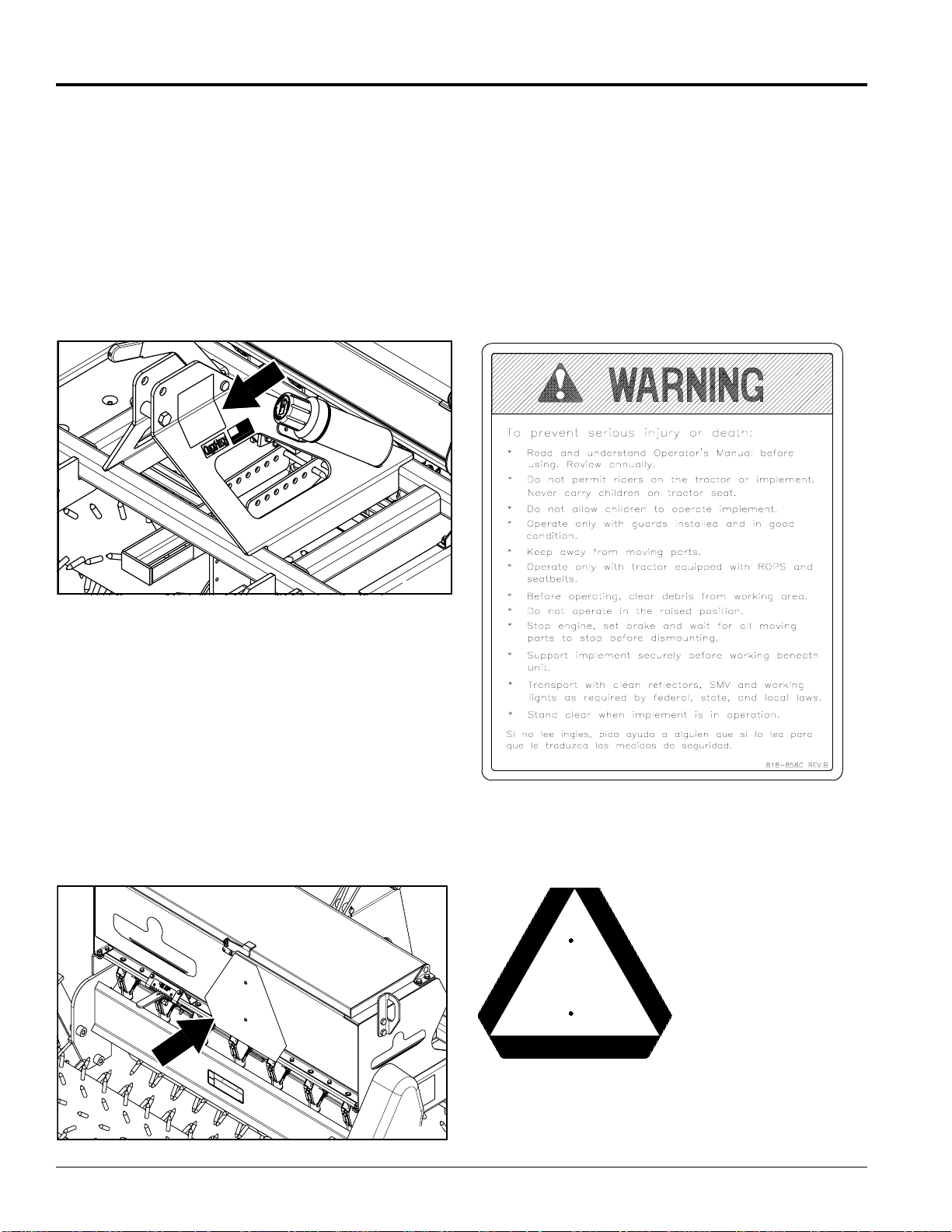
Table of Contents
Important Safety Information
Safety Labels
Your All Purpose Seeder comesequipped withall safety
labels in place. They were designed to help you safely
operate your implement. Read and follow their
directions.
1. Keep all safety labels clean and legible.
2. Replace all damaged or missing labels. To order new
labels go to your nearest Land Pride dealer or visit our
dealer locator at landpride.com.
3. Some new equipment installed during repair requires
safety labels to be affixed to the replaced component as
Land Pride
specified by Land Pride. When ordering new components
make sure the correct safety labels are included in the
request.
4. Refer to this section for proper label placement.
To install new labels:
a. Clean the area the label is to be placed.
b. Spray soapy water on the surface where the label is to
be placed.
c. Peel backing from label.Pressfirmlyontothe surface.
d. Squeeze out air bubbles with the edge of a credit card.
24932
818-858C
warning: General Information
24934
APS1548, APS1560, APS1572 & APS1586 All Purpose Seeder 313-354M
4
818-055C
SMV: Slow Moving Vehicle
5/13/08
Page 7
Land Pride
Important Safety Information
Table of Contents
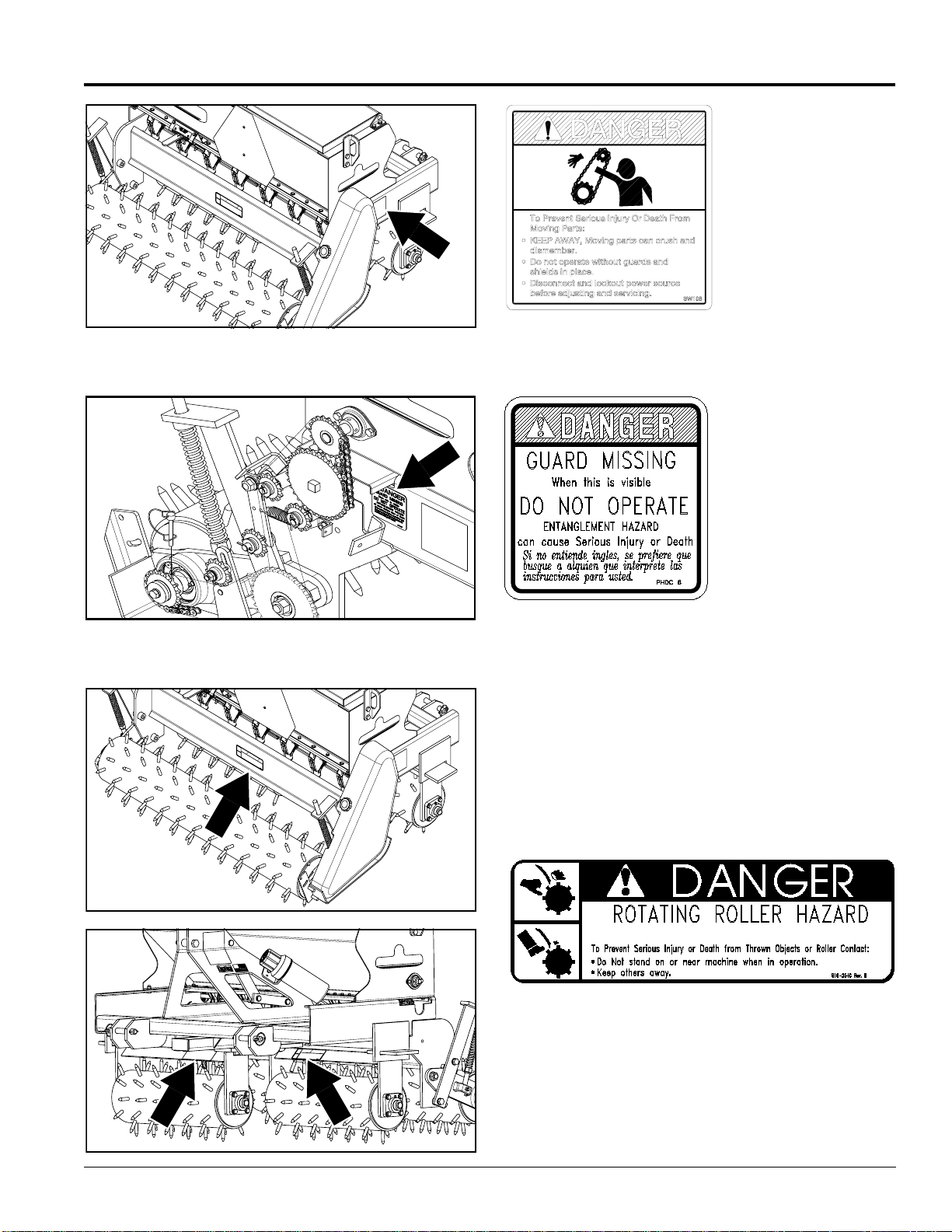
24934
24938
838-111C
DANGER: Keep away,
Moving Parts
818-543C
DANGER:GuardMissing
(Beneath Guard)
5/13/08
24934
KEEP AWAY
818-254C
DANGER: Rotating Roller Hazard
25512
APS1548, APS1560, APS1572 & APS1586 All Purpose Seeder 313-354M
5
Page 8
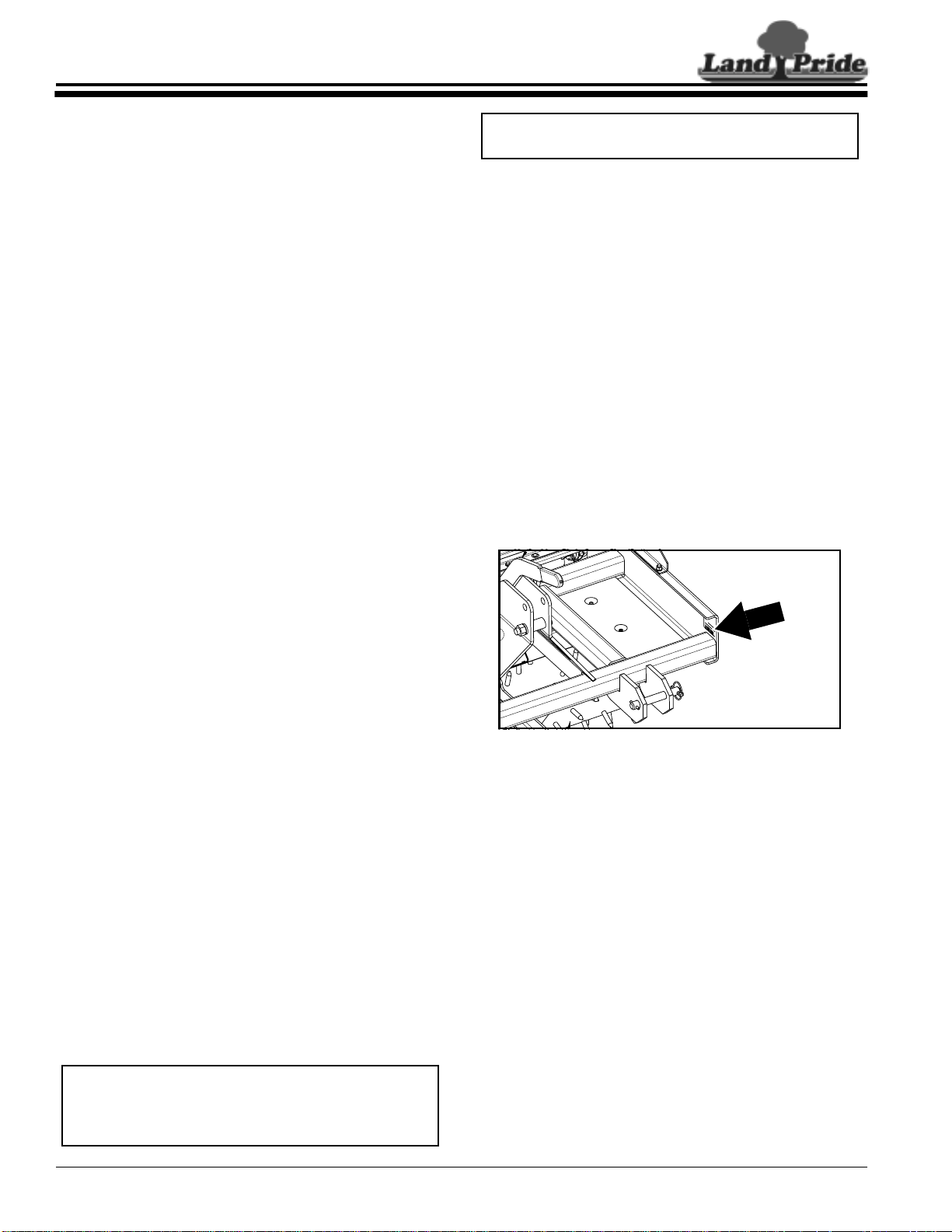
Table of Contents
Introduction
Introduction
Land Pride welcomes you to the growing family of new
product owners.
This All Purpose Seeder has been designed with care
and built by skilled workers using quality materials.
Proper assembly, maintenance and safe operating
practices will help you get years of satisfactory use from
the machine.
Application
The APS1548, APS1560, APS1572 & APS1586 All
PurposeSeedersareexcellentcombinationplantingand
cultivation tools for golf courses, school systems,
municipalities, rental yards, construction companies,
sports fields, and college campuses. Their narrower
widths make them effective in seeding applications on
residential lots, grassy medians, grassy parkings or
right-of- ways adjacent to sidewalks, community parks,
sporting facilities, and golf courses. Unlike wider models
of seeders these units will do a more effective job of
planting in areas where undulations, moguls, and
depressions are prevalent.
The seed box is equipped with our standard fluted seed
cups and an agitator enabling highly accurate and
uniform delivery of most turf grass seeds as well as a
wide variety of other seeds ranging from alfalfa to peas.
The spiked front rollers can be adjusted for more or less
“crab-action cultivation” making theman ideal choice for
opening up and planting in hard or thatchy soil profiles.
See“Section 5: Specifications& Capacities” on page
25 and “Section 6: Features andBenefits” on page26
for additional product information.
Land Pride
NOTE: A special point of information that the
operator must be aware of before continuing.
Owner Assistance
The Warranty Registration card should be filled out by
the dealer at the time of purchase. This information is
necessary to provide you with quality customer service.
If customer service or repair parts are required contact a
LandPridedealer. A dealer has trained personnel, repair
parts and equipment needed to service the All Purpose
Seeder.
The parts on your APS1548 or APS1572 seeder have
been specially designed and should only be replaced
with genuine Land Pride parts. Therefore, should your
seeder require replacement parts go to your Land Pride
Dealer.
Serial Number Plate
For prompt service always use the serial number and
modelnumber when ordering partsfromyour Land Pride
dealer.Besuretoincludeyourserialandmodel numbers
incorrespondencealso. Refer to Figure 1forthelocation
of your serial number plate.
Using This Manual
•
This Operator’s Manual is designed to help familiarize
you with safety, assembly, operation, adjustments,
troubleshooting, and maintenance. Read this manual
and follow the recommendations to help ensure safe
and efficient operation.
• The information contained within this manual was
current at thetime of printing. Some partsmay change
slightly to assure you of the best performance.
• To order a new Operator’s or Parts Manual contact
your authorized dealer. Manuals can also be
downloaded, free-of-charge from our website at
www.landpride.com or printed from the Land Pride
Service & Support Center by your dealer.
Terminology
“Right” or “Left” as used in this manual is determined by
facing the directionthe machine will operate while in use
unless otherwise stated.
Definitions
IMPORTANT: A special point of information related
to its preceding topic. Land Pride’s intention is that
this information should be read and noted before
continuing.
24940
Serial Number Plate Location
Figure 1
Further Assistance
Your dealer wants you to be satisfied with your new All
PurposeSeeder. If for any reasonyoudonot understand
any part of this manual or are not satisfied with the
service received, the following actions are suggested:
1. Discuss the matter with your dealership ser vice
manager making sure he is aware of any problems
youmay haveand that he has had the opportunity to
assist you.
2. If you are still not satisfied, seek out the owner or
general manager of the dealership, explain the
problem and request assistance.
3. For further assistance write to:
Land Pride Service Department
1525 East North Street
P.O. Box 5060
Salina, Ks. 67402-5060
E-mail address
lpservicedept@landpride.com
APS1548, APS1560, APS1572 & APS1586 All Purpose Seeder 313-354M
6
5/13/08
Page 9
Land Pride
Section 1: Assembly & Set-up
Section 1: Assembly & Set-up
Table of Contents
Tractor Requirements
Tractor horse power and hitch category should be within
the range noted below. Tractors outside the horsepower
range must not be used.
• Tractor Horse Power Rating
APS1548, APS1560 & APS1572 . . . . . . . . . . . 65 HP
APS1586 . . . . . . . . . . . . . . . . . . . . . . . . . . . . . 80 HP
• Hitch Category
APS1548, APS1560 & APS1572 . . . . . . . . . . . . Cat. I
APS1586 . . . . . . . . . . . . . . . . . . . . . . . . . . .Cat. I & II
Make certain tractor’s 3-point lifting capacity and weight
is capable of lifting and controlling the seeder under all
operating conditions. Refer to “Specifications &
Capacities” on page 25 for seeder weight.
NOTE: Ballast may needto be addedto your tractor
to maintain steering control. Refer to your tractor’s
operator manual to determine if additional ballast is
needed.
The lower 3-Point arms must be stabilized to prevent
side-to-side movement. Most tractors have sway blocks
or adjustable chains for this purpose.
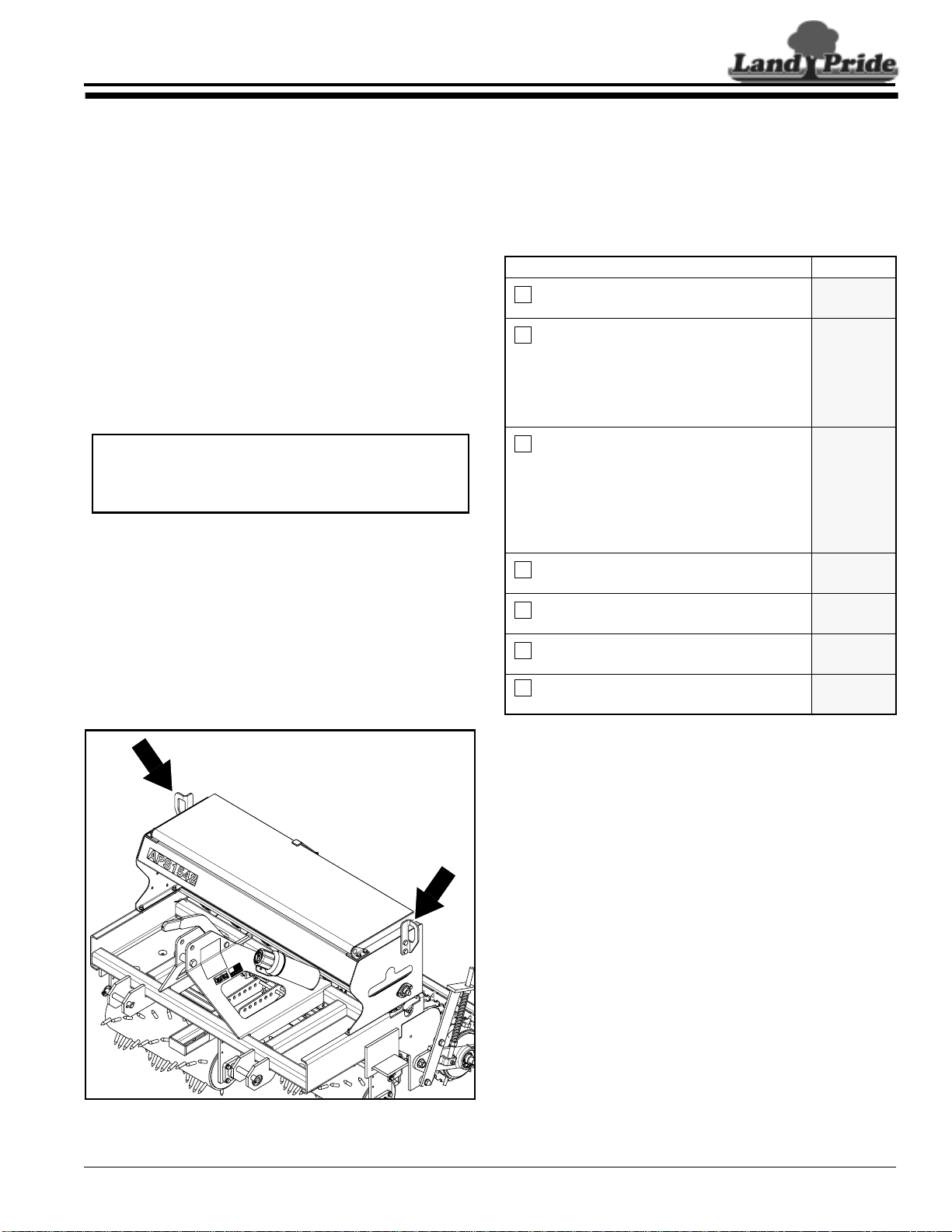
Sling Bracket
Refer to Figure 1-1:
The sling brackets allow points at each end to hook a
chain for lifting the unit. When hooking a chain to the
sling brackets, be certain toeither use a spreader baron
thechain or use alongchainto prevent bending thesling
brackets.
Dealer Preparations
This All Purpose Seeder has been assembled at the
factory.Somepreparation will be necessary to attachthe
seederto the customer’stractor.Make sure the intended
tractor conforms to “Tractor Requirements”.
Pre-Assembly Checklist
Check Reference
All major frame components Operator’s
Manual
Location of fasteners and pins.
NOTE: All hardware from the factory has
been installed in the location where it will
be used. If a part is temporarily removed
for assembly reasons, remember where
it goes. Keep parts separated.
Be sure the part gets used in the correct
location. Use parts manual to identify
location of parts that have been removed
and are unsure where to replace them.
By double checking while you assemble,
you will lessen the chance of using a bolt
incorrectly that may be needed later.
All working parts are moving freely, bolts
are tight and cotter pins are spread.
All grease fittings are in place and
lubricated.
Proper tension and alignment on all
drive chains.
Safety decals are correctly located and
legible. Replace if damaged.
Operator’s
Manual
Parts
Manual
Operator’s
Manual
Section 4
Page 23
Section 4
Page 22
Pages
4 & 5
5/13/08
Sling Brackets
Figure 1-1
24932
APS1548, APS1560, APS1572 & APS1586 All Purpose Seeder 313-354M
7
Page 10
Section 1: Assembly & Set-up
Table of Contents
Land Pride
Mud Scraper Installation (Optional)
Optional mud scrapers are available from your local
Land Pride dealer.A scraper bundleconsists of one rear
roller scraper and two front roller scrapers and are
identified by the rear roller type and seeder planting
width.
Land Pride Mud Scrapers
Part No. Part Description
APS1548
313-431A SPIKE SCRAPER BUNDLE . . . S/N 567003+
313-432A PACKER SCRAPER BUNDLE . S/N 567003+
APS1560
313-458A SPIKE SCRAPER BUNDLE
313-459A PACKER SCRAPER BUNDLE
APS1572
313-429A SPIKE SCRAPER BUNDLE . . . . S/N 547969+
313-430A PACKER SCRAPER BUNDLE. . S/N 547969+
APS1586
313-449A SPIKE SCRAPER BUNDLE
313-453A PACKER SCRAPER BUNDLE
Refer to “Torque Values Chart For Common Bolt Size”
on page 28 when tightening hardware.
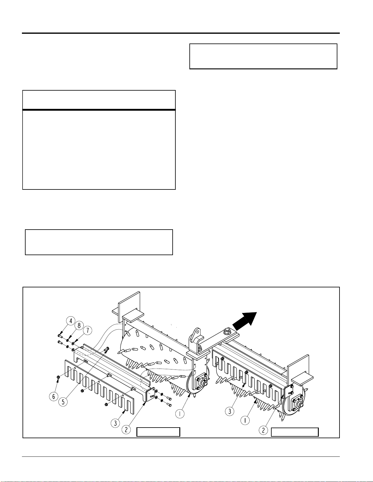
Front Mud Scrapers
Refer to Figure 1-4:
IMPORTANT: Some units will not accept a Mud
Scraper attachment. Please be sure of your serial
number to verify.
NOTE: Do not tighten bolts (#4 & #5) until after
adjustments have been made. See “Mud Scraper
Adjustment (Optional)” on page 14 for instructions.
1. Attach spike scrapers (#3) to scraper hangers (#2)
with 3/8"-16 x 1 1/4" GR5 round head square neck
bolts(#5)andhexflangelocknuts(#6).Drawnuts up
snug, do not tighten until after completing
adjustments in Section 3.
2. Attach scraper hangers (#2) to the front rollers with
four 3/8"-16 x 1" GR5 hex head cap screws (#4),
3/8" lock washers (#8) and 3/8" flat washers (#7).
Draw nuts up snug, do not tighten until after
completing adjustments in Section 3.
Rear Mud Scraper
Refer to Figure 1-5 on page 9:
The instructions below apply to both the rear packer
roller and rear spike roller.
1. Lower rear roller to ground level to compress
spring (#6). Adjust 3-point lift height to make sure
roller arm (#1) is positioned so that there is space
between the arm and stop blockslocated above and
below the arm.
2. Support seeder frame at this height to keep seeder
frame from creeping lower during assembly.
3. Shut tractor engine off and engage parking brake.
4. Attach vice grips tightly to the spring rod and tight
against the spring rod guide bar to retain spr ing
compression.
5. Loosen bearing set collar screw (#2) and remove
locknut(#3), cap screws (#4)andlockwashers (#5).
Keep hardware for reuse.
Left Hand Roller
Front Mud Scraper Installation
APS1548, APS1560, APS1572 & APS1586 All Purpose Seeder 313-354M
8
Figure 1-4
vel
ra
Direction
of T
Right hand Roller
25607
5/13/08
Page 11

Land Pride
Section 1: Assembly & Set-up
Table of Contents
24977
Important: Make sure there is space
between the roller arm (#1) and stop
blocks above and below the arm and
that the arm is not tight against a stop
block before attaching a vice grip to
the spring rod.
Attach a vice grip tightly to
the spring rod at this location.
5
3
4
Roller Arm Disassembly Position
Figure 1-5
Spring Rod
SpringRod
Guide Bar
6
1
2
Refer to Figure 1-6 below & Figure 1-7 on page 10:
6. Pull roller arm assembly (#1) away from rear roller
end plate and insert two 1/2"-13 x 1 1/2" GR5 hex
cap screws (#12) from the inside as shown.
7. Reinstall roller arm assembly (#1)to the seeder side
plate with existing 3/4"-10 hex flange lock
nut (#3), 5/8"-11 GR5 hexhead cap screws (#4) and
lock washers (#5). Torque all hardware including
bearing set collar screw (#2).
8. Remove vice grip from spring rod.
9. Attach left hand scraper mount (#10) to the left side
roller arm (#1) with hex flange lock nuts (#14).
Tighten lock nuts (#14) to the correct torque.
Special Instructions For Packer Roller
Refer to Figure 1-6:
NOTE: Do not tighten bolts (#16) until after
adjustments have been made. See “Mud Scraper
Adjustment (Optional)” on page 14 for instructions.
1. Attach rear roller scraper (#9) to chain guard
mount (#7) with two 3/8"-16 x 1 1/4" GR5 hex head
cap screws (#11), 3/8" flat washers (#15), 3/8" lock
washers (#16) and hex nuts (#13). Draw nuts up
snug, do not tighten until after completing
adjustments in Section 3.
2. Attach opposite end to scraper mount (#10) with two
3/8"-16 x 1 1/4" GR5 hex head cap screws (#11),
3/8" flat washers (#15), 3/8" lock washers (#16) and
hex nuts (#13). Draw nuts up snug, do not tighten
until after completing adjustments in Section 3.
5/13/08
Rear Mud Scraper Installation to Packer Roller
Figure 1-6
APS1548, APS1560, APS1572 & APS1586 All Purpose Seeder 313-354M
25605
9
Page 12

Section 1: Assembly & Set-up
Table of Contents
Land Pride
Special Instructions For Spike Roller
Refer to Figure 1-7:
NOTE: Do not tighten bolts (#11 & #18) until after
adjustments have been made. See “Mud Scraper
Adjustment (Optional)” on page 14 for instructions.
1. Attach spike scrapers (#17) to scraper hanger (#9)
with 3/8"-16 x 1 1/4" GR5 round head square neck
bolts(#18) and hexflangelocknuts(#19). Draw nuts
up snug, do not tighten until after completing
adjustments in Section 3.
2. Attach scraper hangers (#9) to chain guard
mount (#7) with two 3/8"-16 x 1 1/4" GR5 hex head
cap screws (#11), 3/8" flat washers (#15) and 3/8"
lockwashers(#16). Secure scraper in placewith hex
nuts (#13). Draw nuts up snug, do not tighten until
after completing adjustments in Section 3.
3. Attach opposite end to scraper mount (#10) with two
3/8"-16 x 1 1/4" GR5 hex head cap screws (#11),
3/8" flat washers (#15) and 3/8" lock washers (#16).
Securecapscrewswithhexnuts(#13).Drawnutsup
snug, do not tighten until after completing
adjustments in Section 3.
Rear Mud Scraper Installation to Spike Roller
APS1548, APS1560, APS1572 & APS1586 All Purpose Seeder 313-354M
10
25606
Figure 1-7
5/13/08
Page 13

Land Pride
Table of Contents
Section 2: Operating Instructions
Section 2: Operating Instructions
Operating Check List
Hazard control and accident prevention are dependent
upon the awareness, concern, prudence and proper
training involved in the operation, transport,
maintenance and storage of the seeder. Therefore, it is
absolutelyessentialthatnooneoperatestheAllPurpose
Seeder without first having read, fully understood and
becometotallyfamiliarwiththeOperator’sManual.Make
sure the operator has paid particular attention to:
• Important Safety Information, pages 1 to 5
• Section 1: Assembly & Set-up, page 7
• Section 2: Operating Instructions, page 11
• Section 3: Adjustments, page 14
• Section 4: Maintenance & Lubrication, page 22
The following information should be known and
inspections made before operating your seeder.
Check Reference
Read and follow all “Safety Rules”
carefully.
Read and follow “T ractor Hook-up”
instructions below.
Read and understand “Operating and
Adjustment Instructions” in this manual
Lubricate seeder as needed. Refer to
“Lubrication”
Check seeder initially and periodically for
loose bolts & pins, “T orque Values Chart”.
Make sure all guards and shields are in
place.
Checkinitially and periodicallyforloose bolts,
pins, and chains.
Inspectseedcups and seedtubes forforeign
matter.
Set speed change sprocket for drive type
desired.
Set seed rate. See “Seed Rate Charts”. Section 3
Important Safety
Information
Section 2
page 11
Operator’s
Manual
Section 4
page 23
Section 8
page 28
Operator’s
Manual
Operator’
Manual
Section 3
page 17
Section 3
page 16
pages 18 to 21
4. Attach tractor’stop center link to the seeder’s top
hitchusinga3/4” diameter hitch pin. Secure hitch pin
with a linch pin.
5. Ensure that the lower hitch arms are blocked to
prevent excessive side movement.
6. Return to tractor and slowly operate controls up and
down to makesure seeder clears tractor tires, frame
and drawbar.Move or removedrawbarif it interferes.
7. Manuallyadjust one ofthe tractor’slower lift arms up
or down to level the seeder from left to r ight.
8. With the seeder resting on level ground, manually
adjust tractor’stop link until the seeder is level from
front to rear.
Transporting
!
When traveling on public roads whether at nightor during the
day,use accessory lights and devices for adequate warning to
operators of other vehicles. Comply with all federal, state and
local laws.
1. This seeder can be transported with a full box of
2. Select a safeground travel speed when transporting
3. Reduce tractor ground speed when tur ning. Leave
4. Shift tractor to a lower gear when traveling over
CAUTION
seed, however; it is best not to do this unless
necessary because the increased weight does
increase the chances for problems on the road.
fromoneareatoanother.Donotexceed20 milesper
hour travel speed. When traveling on roadways,
transport in such a way that faster moving vehicles
may pass you safely.
enough clearance so the seeder does not contact
obstacles such as buildings, trees or fences.
rough or hilly terrain.
Filling the Seed Box
Tractor Hook-up
!
Tractor hook-up to equipment is dangerous and can result in
serious injury or death. Do not allow anyoneto stand between
the seeder and tractor during hook-up operations. Do not
operate hydraulic 3-point lift controls while someone is
directly behind the tractor or near the seeder.
1. Slowly back tractor up to the All Purpose Seeder
2. Engage tractor park brake, shut tractor engine off
3. Attach tractor’s3-Point lower links to the seeder’s
5/13/08
DANGER
while using the tractor’s 3-point hydraulic control to
align the tractor’s lower hitch link holes with the
seeder’s clevis lug holes.
and remove key before dismounting from tractor.
lower hitch clevises using 7/8” diameter hitch pins.
Secure hitch pins with linch pins.
APS1548, APS1560, APS1572 & APS1586 All Purpose Seeder 313-354M
!
Always lower the All Purpose Seeder to the ground before
filling and checking seed level in the seed box. This will keep
the rollers from turning while working around them.
Refer to Figure 2-1 on page 12:
1. Always lower the All Purpose Seeder to the ground,
2. Release lid latch handle (#5) and open seed box
3. Fill seed box from the rear while standing on the
CAUTION
engage tractor park brake, shut tractor engine off
and remove key before filling the seed box.
lid (#1) until over center latch arms (#2) have locked
in place. Doingthis willkeep the lid from fallingwhile
filling the box.
ground.Do not step orclimbon the rear roller(#3)to
fill the seed box. Make sure the rear roller (#3) is on
the ground so it cannot turn while filling the box.
11
Page 14

Section 2: Operating Instructions
Table of Contents
Land Pride
4. The bag opener(#4) (sharp point on top ofthe baffle
plate) can be used to tear open the seed bags.
5. Maker certain the seed box is filled uniformly to
insure one side dose not run out of product ahead of
the other side.
6. Close lid by pulling on the handle of the over center
latcharms (#2) with one handwhileholdingthelid up
with the other hand. Lower lid gently while keeping
hands and fingers clear.
7. Lock lid down with lid latch handle (#5) to keep
moisture out.
1
5
2
4
Seed Rate
Chart
Seed Splash
Plate
3
The condition of soil and type of vegetation will
determine front roller angle. Soil that has been preworked will not require as aggressive an angle as hard
soil or soil with unwanted vegetation. The drive sprocket
can be disengaged from the rear roller to make several
passes over the soil beforeseeding. Grass that you plan
to seed over, without killing,should havethe front rollers
set at 0 degrees or at a slight angle to remove thatch.
Seeds drops in frontof the rearroller to allowthe roller to
firm the soil around the seeds. The rear roller assembly
floats up and down under spring tension to follow field
terrain.
Operating the Seeder
!
Do not use the seeder for pulling fence posts, stumps, etc.,
lifting objects, carry objects or towing other equipment. Any
of the above can result in equipment damage, serious bodily
injury or death.
Never carry a person on the seeder. A person can become
entangled in the seeder or fall and be ran over causing serious
injury or death.
WARNING
!
DANGER
IMPORTANT: Reference Figure 3-3 on page 15.
Never back up with rear roller drive sprocket (#2)
engaged (retaining pin (#1) installed) and roller in
contact with the ground. This will loosen the drive
chain and damage the seeder.
25511
Seed Box With Lid Open
Figure 2-1
How the Seeder Works
The following is a brief description of how your
All Purpose Seeder works.
The power to drive the seed cups comes from the rear
rollerturning against the ground whiletraveling.Poweris
transmitted from the rear roller through roller chains to
the seed cups. Seed is metered out of the cups at a rate
proportional to the distance driven. Thisensures that the
rate applied in pounds per 1000 square feet or pounds
per acre remains constant as ground speed is varied.
Cup metering speed can be adjusted to either a high or
lowrange by changingthe speed change sprocket.Also,
the rate seed falls through the seed cups is adjustable
using the seed rate adjustment lever located at the back
of the seeder.
Thefrontrollers cultivate the soil, crushesclods,presses
down small stones and forms a seedbed. They can be
angled form 0 degrees (non-aggressive) to 20 degrees
(very aggressive).
Always disconnect drive sprocket from rear roller
before backing up with roller on the ground.
IMPORTANT: Never make sharp tur ns with any of
the rollers in contact with the ground. Alwayslift unit
up off the ground when making sharp turns.
IMPORTANT: Attach seeder to a tractor before
calibrating it for proper seed dispersal rate.
1. Contact your local utility services so that they may
mark location of any under ground utility services in
the area. Thoroughly inspect the work area yourself
for buried pipelines, sprinkler heads and any
unforeseen objects. Mark any potential hazards.
2. This seeder can be transported with a full box of
seeds. It is best not to do this unless necessary
because the increased weight does increase the
chances for problems onthe road. Do not exceed20
miles per hour.
3. Calibrate your seeder sprocket speed and seed cup
rate adjustment lever based on type of seed you are
using.Calibrationinformationislocatedontheinside
of your box lid or on page 17.
APS1548, APS1560, APS1572 & APS1586 All Purpose Seeder 313-354M
12
5/13/08
Page 15

Land Pride
Section 2: Operating Instructions
Table of Contents
4. Make sure each seed cup door handle is set at the
same height acrossthe seeder. The highestposition
is usually used for grass seeds.
5. Be sure all bolts and nuts are tight.
6. Be certain all guards are in place and secure.
7. Clearareatobeseededofrocks,branches and other
foreign objects. Mark any potential hazards.
8. Tall grass and weeds should be mowed before
seeding.
9. Never allow anyone to ride on the seeder.
10. Adjust front rollers to desired angle. Make some
practice runs with drive sprocket disconnected to
determine the best roller angle for your application.
11. Do not back up while seeder is on the ground unless
rear roller is disconnected from drive sprocket.
12. Disconnect rear roller from drive sprocket before
backing up seeder to clean front and rear mud
scrapers of debris.
13. Disconnect drive sprocket if more than one pass is
required to prepare a seed bed before seeding.
14. Reconnect drive sprocket when ready to seed.
15. Do not make sharp turns while the seeder is on the
ground.
16. Seeding should not be donein wet conditions as soil
will stick to the rollers.
17. At first begin seeding at a slow forward speed and
shift up until the desired speed is achieved.
Maximum speed to plant seed will vary according to
soil conditions.
18. After seeding the first 50 feet, stop and check to see
that the seeder is adjusted properly.
Parking the Seeder
The following steps should be done when preparing to
store the seeder or unhitch it from the tractor. See also
“Section 4: Maintenance & Lubrication” on page 22
for additional information on long term storage of your
seeder.
1. Park the All Purpose Seeder on a level, solid area.
2. Lower seeder to level ground or onto blocks
supporting the seeder just above ground level.
3. Shut off tractor engine and engage parking brake.
4. Un-hook 3-point hitch from tractor. Reinstall hitch
pins and linch pins in seeder hitch for storage.
5. See ““Cleaning and Storing” on page 22” if the
seeder is not going to be used for a long time.
General Operating Instructions
Once you have read the Operator’s Manual, properly
installed the seeder to the tractor’s 3-point hitch, ran
through the Operating Check List, filled the box with
seed, and calibrated the unit for proper seed rate
delivery, it’s time to do some serious seeding.
The All Purpose Seeders have ground driven seed
delivery systems. The power to drive the seeder comes
from the forward momentum ofthe tractor. As the tractor
moves forward the ground driven rear roller transfers
power via chain driven sprockets to the seed metering
system. Seed rate remains constant and in direct
proportion to the distance traveled and is affected very
little by actual ground speed.
As the front spiked rollers pass over areas to be seeded
they open up the soil profile. The more critical the angle
adjustment on the front rollers, the more aggressive the
cultivating action will be. Seed is then delivered at the
precise predetermined rate through the wind guarded
seed drop area between the front and rear rollers. The
rear roller then presses seed into firm contact with the
soil to promote a superbly high germination rate.
Seeding should not be attempted in wet or muddy
conditions.
Now that you understand how it works, it is time to begin
seeding. You may want to make a few passes with the
seeder drive sprocket disconnected just to make sure
your front rollers are adjusted to the proper angle and to
determine correct ground speed for cultivating the soil
profile to your expectations. Ridging of loose soil is
possible when the front rollers are set at and angle and
your ground speed is to fast. Slow your ground speed to
eliminate ridging. Re-engage the seeder drive sprocket
once you are satisfied that the proper amount of soil
opening action is being achieved.
You should already have removed any large stones or
obstaclesfrom the area you plantoseed.Line the tractor
up for the first pass and choose a tractor gear selection
that will deliver a ground speed of approximately
3-5 mph. Lower the three-point hitch and seeder slowly
to the ground and begin driving forward, slowly at first
untilyou get comfortable with whatyouare doing. As you
approachthe end of the lane youareseeding,slow down
and come to a stop while simultaneously raising the
seeder off of the ground. With the seeder raised, line up
for your next pass and repeat the process. Look back
oftenandavoidmakingverysharpturnswithyourseeder
on the ground ifyou expect to developa uniform seeding
pattern. The more experienced you become the better
you will get at developing beautiful seed plots and
beautiful lawns.
Whenever you are done seeding always clean the
seeder out and perform all maintenance prescribed in
the Operator’s Manual. Never leave seed stored in the
hopper for prolonged periods. Never dismount your
tractor without first coming to a full stop, turning off the
tractor, and setting the park brake. Never allow riders on
the tractor when working with any rear mounted
implement installed.
With a little practice you should get very good at
developing lush green stands of grass with your Land
Pride All Purpose Seeder.
5/13/08
APS1548, APS1560, APS1572 & APS1586 All Purpose Seeder 313-354M
13
Page 16

Section 3: Adjustments
Section 3: Adjustments
Table of Contents
Land Pride
Front Roller Angle Adjustment
Refer to Figure 3-1:
NOTE: Gangslide (#1) is shown in its furthest back
position. In this position, both bent pins (#6) are in
front of the gang slide as shown. In all other
positions, one bent pin is in back of the gang slide
and the other is in front of the gang slide.
1. Lowerseeder frame onto blocks supporting the front
rollers just above ground level to allow the front
rollers to move freely.
2. Shut tractor engine off and engage parking brake.
3. Remove bent pins (#6) and operate roller angling
lever(#3) to reposition front rollers (#2) to the desired
angle.
4. Replacebentpins (#6) with one on each sideofgang
slide (#1). Securebent pins with hair pin cotters (#5).
5. Remove support blocksand lower seeder to ground
level.
IMPORTANT: If 1" hex flange lock nuts (#4) have
beenloosened, they should be retightened untilthey
make contact with gang slide (#1) and then backed
off 1/3 revolution (2 hex flats). Some additional
backing off of the nuts may be necessary to allow
the gang slide to move easily when adjusting roller
angle with lever (#3).
Mud Scraper Adjustment (Optional)
Refer to “Torque Values Chart For Common Bolt Size”
on page 28 when tightening hardware.
Refer to Figure 3-2:
Front Mud Scrapers
1. Loosen3/8"-16hexnuts(#1)atboth ends of the
left front mud scraper (#3).
2. Rotate teeth of mud scraper towards the front roller
to increase removal of mud and debris and away if
scraper teeth are interfering with the roller.
3. Retighten the four 3/8"-16 GR5 hex head bolts and
nuts (#1 & #2) to the proper torque.
4. Repeat steps 1, 2 & 3 above for the r ight front mud
scraper.
Rear Mud Scrapers
1. Loosen3/8"-16hexnuts(#4)atboth ends of the
rear mud scraper (#6).
2. Rotate teeth of mud scraper towards the front roller
to increase removal of mud and debris and away if
scraper teeth are interfering with the roller.
3. Retighten the four 3/8"-16 GR5 hex head bolts and
nuts (#4 & #5) to the proper torque.
Special Instructions for Spike Rollers
1. With front and rear spike rollers off the ground,
loosenround head square neckbolts(#7) and adjust
front and rear scrapers left or right to align slots up
with the roller spikes. Rotate spike rollers one or
morerevolutionstoverifyspikesare not touching the
scraper teeth.
2. Tightenfront and rear 3/8"-16x1 1/4" GR5 bolts (#7)
to the correct torque.
24940
Front Roller Adjustment
(Gang Slide #1 Shown Positioned Fully Back)
Figure 3-1
APS1548, APS1560, APS1572 & APS1586 All Purpose Seeder 313-354M
14
1
25608
7
6
67
4
2
3
5
Mud Scraper Adjustments
Figure 3-2
5/13/08
Page 17

Land Pride
Table of Contents
Section 3: Adjustments
Drive Chain Engagement
Refer to Figure 3-3:
Soil that isvery hard or with a lot ofunwanted vegetation
may require several passes with the front rollers set at a
very aggressive angle before planting begins.
Disengage drive chain from the rear roller while making
thesepassesandengagedrivechainwhen ready to start
planting seed.
1. Lower seeder frame onto blocks supporting rear
roller just above ground level to allow roller to turn
freely.
2. Shut tractor engine off and engage parking brake.
3. Remove drive guard (not shown).
4. Remove wire retaining pin (#1) from drive
sprocket (#2). Store retaining pin for reuse.
5. Replace drive guard.
NOTE: If needed, set front roller angle before
lowering seeder to ground level. See Front Roller
Angle Adjustment on this page.
6. Remove suppor t blocks and lower seeder to ground.
1
2
24938
Disengage Drive Chain
Figure 3-3
5/13/08
APS1548, APS1560, APS1572 & APS1586 All Purpose Seeder 313-354M
15
Page 18

Table of Contents
Section 3: Adjustments
Speed Change Sprocket
The All Purpose Seeder is designed with two drive
speeds to accommodate different seed sizes and seed
dispersal rates. The two drive speeds are high range
(fast speed) and low range (slow speed).
High Range Set-up
Refer to Figure 3-4:
1. Loosen 3/8" flange lock nut(#1) and drive tension
sprocket (#2). Remove drive chain (#3) from speed
change sprocket (#6).
2. Remove 5/8” nut (#4) and 5/8” flat washer (#5).
3. Pull idler sprocket (#8) away from driven
chain (#7) and remove driven chain.
4. Rearrange speed change sprocket(#6) so that the
larger 35 tooth sprocket is behind the smaller 19
tooth sprocket as shown.
5. Secure sprocket with 5/8" flat washer (#5) and
5/8" - 11 nut (#4). Tighten nut to correct torque.
6. Drivechain(#3)shouldbe65pitcheslonganddriven
chain (#7) 101 pitches long. If dr ive chain has 73
pitches, remove 8 pitches from it and add those 8
pitches to the driven chain.
7. Replace101 pitch driven chain (#7) firstandthen the
65 pitch drive chain (#3).
8. Makesure idler sprocket(#8) is pressing against the
driven chain.
9. Retention dr ive chain (#3) by pressing down on idler
sprocket(#2). When tensioned properly,tighten 3/8"
flange lock nut (#1) to maintain that tension.
Low Range Set-up
Refer to Figure 3-5:
1. Loosen 3/8" flange lock nut(#1) and drive tension
sprocket (#2). Remove drive chain (#3) from speed
change sprocket (#6).
2. Remove 5/8” nut (#4) and 5/8” flat washer (#5).
3. Pull idler sprocket (#8) away from driven
chain (#7) and remove driven chain.
4. Rearrange speed change sprocket(#6) so that the
larger 35 tooth sprocket is in front of the smaller 19
tooth sprocket as shown.
5. Secure sprocket with 5/8" flat washer (#5) and
5/8" - 11 nut (#4). Tighten nut to correct torque.
6. Drivechain(#3)shouldbe73pitcheslonganddriven
chain (#7) 92 pitches long. If dr iven chain has 101
pitches, remove 8 pitches from it and add those 8
pitches to the drive chain.
7. Replace 93 pitch driven chain (#7) first and then the
73 pitch drive chain (#3).
8. Makesure idler sprocket(#8) is pressing against the
driven chain.
9. Retention dr ive chain (#3) by pressing down on idler
sprocket(#2). When tensioned properly,tighten 3/8"
flange lock nut (#1) to maintain that tension.
Land Pride
No. 40 Chain
92 + 8 + Offset Link
= 101 Chain Pitches
2
High Range Sprocket Arrangement & Chain Pitches
No. 40 Chain
92 + Offset Link
= 93 Chain Pitches
7
8
No. 40 Chain
1
7
3
64 + Offset Link
= 65 Chain Pitches
Figure 3-4
35T Sprocket
LocatedBehind
19T Sprocket
6
4 5
35T Sprocket
In Front Of
19T Sprocket
8
2
No. 40 Chain
3
1
Low Range Speed Change & Chain Pitches
64 + 8 + Offset Link
= 73 Chain Pitches
Figure 3-5
6
4 5
24936
24935
APS1548, APS1560, APS1572 & APS1586 All Purpose Seeder 313-354M
16
5/13/08
Page 19

Land Pride
Section 3: Adjustments
Table of Contents
Seeding Adjustments
1. Use seed rate charts beginning on page 18 to
determine correct seeding rate. Make adjustments
as follows:
a. Decide whether your drive needs to be set-up for
lowrange or high range. If necessary, change the
speed change sprocket to accommodate the
correct speed range. See “Speed Change
Sprocket” on page 16.
Refer to Figure 3-6:
IMPORTANT: Use seed rate charts as a guide.
There are many factors which will affect seeding
rates: seed treatment, weight of seed, soil surface
condition and rear roller slippage. Minor
adjustments to the seed ratehandle may be needed
to compensate for these factors.
b. Locate seed rate adjustment lever at rear of
seeder and move it to indicator number obtained
from the seed rate charts. For best results, first
moveadjustmentleverall the wayto the left. Then
movelevertodesiredsetting,movingfromalower
to a higher number.
• Increase seed rate setting if the seed is lighter
than average.
• Decrease seed rate setting if seed is heavier
than average.
2. Complete the following procedure to calibrate
dispersal rate for your specific seed.
a. Place several pounds of seed over three of the
seed cups at the outboard end of the seeder. Do
not allow any of the seed to reach other cups.
b. Lower seeder frame onto blocks supporting rear
roller just above ground level to allow rollerto turn
freely.
NOTE: Rotate rear roller by grasping the roller and
pulling away from the seeder at the bottom of the
roller and pushing toward the seeder at the top.
c. Rotate rear roller to make sure drive system is
working properly and seed cups are free from
foreign matter.
d. Place a drop cloth under the seeder to collect all
seeds that are metered out.
e. Be sure tocheck the three seedcupsto make sure
each cup has plenty of seed falling into it and no
other cups are receiving seed.
f. Rotate rear roller as noted in table below.
Model
No
APS1548 103 rotations 450 rotations
APS1560 89 rotations 388 rotations
APS1572 73 rotations 319 rotations
APS1586 61 rotations 266 rotations
Rear Roller Rotations to Cover
1000 Sq. Ft. 1/10 ACRE
g. Weigh the seed which has been metered out and
divide that weight by three to get the number of
pounds metered by each seed cup. If your weight
is in ounces, divide the weight by 48 to get the
number of pounds metered by each seed cup.
h. Next, multiply number of pounds per cup by
number of cups on your seeder to arrive at total
pounds per 1000 sq. ft. or pounds per 1/10 acre.
i. If calculations are based on 1/10 acre, multiply
total pounds by 10 to arrive at total pounds per
acre.
j. If this figure (total pounds) is different than
desired, then readjust your seed cup adjustment
lever accordingly.
3. You may want to repeat calibration procedure if
results of your calibration vary greatly from
suggested settings on the chart.
NOTE: To determine seed rates for seeds not listed
onthecharts,compareweight and size to those listed
in the seed rate charts and use a similar setting.
Follow steps 4 and 5 to calibrate seed rate.
IMPORTANT: Remember, field conditions willaffect
seedingrates.Whenseeding,checkamountofseed
youareusing by noting acres orsquarefeetseeded,
amount of seed added to seeder, and level of seed
in the seed box. You may need to adjust the seeding
rate slightly to compensate for field conditions if you
suspect that you are seedingmore or lessseed than
desired; and you have accurately calibrated the
seeder for your seed.
IMPORTANT: This seeder is equipped with a fourposition door on each seed cup. The highest handle
position is for small seeds, the second and third
positions are for larger seeds. Grass seed
applications usually require the highest position.
MAKE SURE all handles are in the same position
before seeding. The wide open position (lowest
position) will allow complete clean out of seed cup.
24937
Seed
Cup
Four-Position
Door Handle
Seed Rate Adjustment Lever
DO NOT open cups to the widest position with seed
in the box unless complete clean out is desired.
Seed Rate Adjustment Handle
Figure 3-6
5/13/08
APS1548, APS1560, APS1572 & APS1586 All Purpose Seeder 313-354M
17
Page 20

Section 3: Adjustments
Table of Contents
Land Pride
Seed Rate Charts (English)
(Pounds per 1000 square foot and Pounds per acre)
Cup Setting 0 5 10 15 20 25 30 35 40 45 50 55 60 65 70 75 80 85 90 95 100
Alfalfa (Pounds per Acre)
High Range 0 54 125 198 269 341 412 485 555 626 699 769 842 913 985 1056 1129 1199 1270 1343 1413
Low Range 0 17 40 63 85 108 131 154 176 198 221 244 267 289 312 335 358 380 402 425 448
Alfalfa (Pounds per 1000 Square Feet)
High Range 0.0 1.2 2.9 4.5 6.2 7.8 9.2 11.1 12.8 14.4 16.1 17.7 19.4 21 22.6 24.3 25.9 27.6 29.2 30.9 32.5
Low Range 0.0 0.4 0.9 1.4 2 2.5 3 3.5 4 4.6 5.1 5.6 6.1 6.6 7.2 7.7 8.2 8.7 9.2 9.8 10.3
Bent Grass (Pounds per Acre)
High Range 0 37 80 115 152 185 206 239 265 293 326 358 380 413 439 467 499 528 554 586 619
Low Range 0 17 29 42 54 66 77 89 99 110 122 131 140 149 159 168 175 184 191 198 205
Bent Grass (Pounds per 1000 Square Feet)
High Range 0.0 0.8 1.8 2.6 3.5 4.2 4.7 5.5 6.1 6.7 7.5 8.2 8.7 9.5 10.1 11.5 12.1 12.7 12.7 13.5 14.2
Low Range 0.0 0.4 0.7 1 1.2 1.5 1.8 2 2.3 2.5 2.8 3 3.2 3.4 3.6 3.9 4 4.2 4.4 4.5 4.7
Bermuda - Unhulled (Pounds per Acre)
High Range 0 61 101 161 206 250 295 341 386 430 475 521 565 610 654 701 745 789 834 880 925
Low Range 0 19 32 51 65 79 93 108 122 136 150 165 179 193 207 222 236 250 264 279 293
Bermuda - Unhulled (Pounds per 1000 Square Feet)
High Range 0.0 1.4 2.3 3.7 4.7 5.8 6.8 7.8 8.9 9.9 10.9 12 13 14 15 16.1 17.1 18.1 19.2 20.2 21.3
Low Range 0.0 0.4 0.7 1.2 1.5 1.8 2.1 2.5 2.8 3.1 3.8 3.8 4.1 4.4 4.8 5.1 5.4 5.7 6.1 6.4 6.7
Buffalo Grass Sharps Improved (Pounds per Acre)
High Range 000225276106130159185213241259293321352371395417430434
Low Range 0001321293846566573839299109118127134143147150
Buffalo Grass Sharps Improved (Pounds per 1000 Square Feet)
High Range 0.0 0 0 0.5 1.2 1.7 2.4 3 3.6 4.2 4.9 5.5 6.2 6.7 7.4 8.1 8.5 9.1 9.6 9.9 10
Low Range 0.0 0 0 0.30 0.5 0.7 0.9 1.1 1.3 1.5 1.7 1.9 2.1 2.3 2.5 2.7 2.9 3.1 3.3 3.4 3.5
Clover - Red (Pounds per Acre)
High Range 0 77 143 202 263 321 380 438 499 557 616 676 734 793 852 913 971 1030 190 1149 1207
Low Range 0 24 45 64 83 102 120 139 158 177 195 214 233 251 270 289 308 326 346 364 383
Clover - Red (Pounds per 1000 Square Feet)
High Range 0.0 1.8 3.3 4.6 6 7.4 8.7 1.1 11.5 12.8 14.2 15.5 16.9 18.2 19.6 21 22.3 23.7 25.1 26.4 27.8
Low Range 0.0 0.6 1 1.5 1.9 2.3 2.8 3.2 3.6 4.1 4.5 4.9 5.4 5.8 6.2 6.6 7.1 7.5 7.9 8.4 8.8
Clover - White (Pounds per Acre)
High Range 0 77 151 224 297 372 444 517 592 664 737 812 884 957 1032 1104 1177 1252 1324 1397 1472
Low Range 0 24 48 71 94 118 141 164 187 211 234 257 280 303 327 350 373 397 420 443 466
Clover - White (Pounds per 1000 Square Feet)
High Range 0.0 1.8 3.5 5.2 6.8 8.5 10.2 11.9 13.6 15.3 16.9 18.7 20.3 22 23.7 25.4 27.1 28.8 30.4 32.1 33.8
Low Range 0.0 0.6 1.1 1.6 2.2 2.7 3.2 3.8 4.3 4.8 5.4 5.9 6.4 7 7.5 8 8.6 9.1 9.6 10.2 10.7
Fescue - Fine Blade, Turf Type (Pounds per Acre)
High Range 0 20 46 75 103 131 160 188 216 242 271 299 327 355 384 412 440 468 497 525 553
Low Range 0 6 15 24 33 42 51 60 69 77 86 95 104 113 122 131 140 148 157 166 175
Fescue - Fine Blade, Turf Type (Pounds per 1000 Square Feet)
High Range 0.0 0.5 1.1 1.7 2.4 3 3.7 4.3 5 5.6 6.2 6.9 7.5 8.2 8.8 9.5 10.1 10.8 11.4 12.1 12.7
Low Range 0.0 0.1 0.3 0.5 0.7 1 1.2 1.4 1.6 1.8 2 2.2 2.4 2.6 2.8 3 3.2 3.4 3.6 3.8 4
Fescue K-31(Pounds per Acre)
High Range 0 0 21 50 83 113 140 165 186 223 243 272 305 328 355 382 48 433 439 450 454
Low Range 00615263544515869768495102110118127134136140141
Fescue K-31 (Pounds per 1000 Square Feet)
High Range 0.0 0.0 0.5 1.1 1.9 2.6 3.2 3.8 4.3 5.1 5.6 6.3 7 7.5 8.2 8.8 9.4 10 10.1 10.3 10.4
Low Range 0.0 0.0 0.1 0.4 0.6 0.8 1 1.2 1.3 1.6 1.7 1.9 2.2 2.3 2.5 2.7 2.9 3.1 3.1 3.2 3.2
Kentucky Blue Grass (Pounds per Acre)
High Range 0 23 48 73 103 125 155 178 205 227 250 274 293 322 334 365 387 406 426 442 455
Low Range 0 8 16 24 34 41 51 58 67 74 82 90 96 106 109 119 127 133 140 145 149
Kentucky Blue Grass (Pounds per 1000 Square Feet)
High Range 0.0 0.5 1.1 1.7 2.4 2.9 3.6 4.1 4.7 5.2 5.7 6.3 6.7 7.4 7.7 8.4 8.9 9.3 9.8 10.1 10.5
Low Range 0.0 0.2 0.4 0.5 0.8 0.9 1.2 1.3 1.5 1.7 1.9 2.1 2.2 2.4 2.5 2.7 2.9 3.1 3.2 3.3 3.4
APS1548, APS1560, APS1572 & APS1586 All Purpose Seeder 313-354M
18
5/13/08
Page 21

Land Pride
Table of Contents
Section 3: Adjustments
Cup Setting 0 5 10 15 20 25 30 35 40 45 50 55 60 65 70 75 80 85 90 95 100
Lovegrass - Sand (Pounds per Acre)
High Range 0 89 140 191 242 293 343 394 445 496 547 598 649 700 751 802 852 925 977 1029 1081
Low Range 0 28 44 61 77 93 109 125 141 157 173 189 206 222 238 254 270 286 302 319 335
Lovegrass - Sand (Pounds per 1000 Square Feet)
High Range 0.0 2 3.2 4.4 5.6 6.7 7.9 9.1 10.2 11.4 12.6 13.7 14.9 16.1 17.3 18.4 19.6 21.3 22.5 23.7 24.9
Low Range 0.0 0.6 1 1.4 1.8 2.1 2.5 2.9 3.2 3.6 4 4.4 4.7 5.1 5.5 5.8 6.2 6.6 6.9 7.3 7.7
Lovegrass - Weeping (Pounds per Acre)
High Range 0 109 176 226 287 343 396 448 501 553 606 658 711 763 816 868 921 973 1026 1078 1133
Low Range 0 35 56 72 91 109 125 142 159 175 192 209 225 242 259 275 292 308 325 342 359
Lovegrass - Weeping (Pounds per 1000 Square Feet)
High Range 0.0 2.5 4 5.2 6.6 7.9 9.1 10.3 11.5 12.7 13.9 15.1 16.3 17.5 18.7 20 21.2 22.4 23.6 24.8 26
Low Range 0.0 0.8 1.3 1.6 2.1 2.5 2.9 3.3 3.6 4 4.4 4.8 5.2 5.6 5.9 6.3 6.7 7.1 7.5 7.8 8.2
Orchard Grass (Pounds per Acre)
High Range 046101520273441495866758594103112121130138146
Low Range 01235791215182225293336404448515558
Orchard Grass (Pounds per 1000 Square Feet)
High Range 0.0 0.1 0.1 0.2 0.3 0.5 0.6 0.8 0.9 1.1 1.3 1.5 1.7 1.9 2.2 2.4 2.6 2.8 3.0 3.2 3.3
Low Range 0.0 0.0 0.0 0.1 0.1 0.2 0.2 0.3 0.3 0.4 0.5 0.6 0.7 0.7 0.8 0.9 1.0 1.1 1.2 1.3 1.3
Rye Grass - Annual (Pounds per Acre)
High Range 0 21 59 95 131 168 204 242 279 315 351 388 426 462 499 535 573 610 646 682 719
Low Range 0 7 19 30 42 53 65 77 88 100 111 123 135 147 158 170 182 193 205 216 228
Rye Grass - Annual (Pounds per 1000 Square Feet)
High Range 0.0 0.5 1.3 2.2 3 3.9 4.7 5.6 6.4 7.2 8.1 8.9 9.8 10.6 11.5 12.3 13.2 14 14.9 15.7 16.5
Low Range 0.0 0.2 0.4 0.7 1 1.2 1.5 1.8 2 2.3 2.6 2.8 3.1 3.4 3.6 3.9 4.2 4.4 4.7 5 5.2
Rye Grass - Perennial (Pounds per Acre)
High Range 0 36 77 115 156 196 234 275 315 353 394 434 475 513 553 594 632 672 713 751 791
Low Range 0 12 24 37 49 62 74 87 100 112 125 138 150 163 175 188 200 213 226 238 251
Rye Grass - Perennial (Pounds per 1000 Square Feet)
High Range 0.0 0.8 1.8 2.6 3.6 4.5 5.4 6.2 7.2 8.1 9 10 10.9 11.8 12.7 13.6 14.5 15.5 16.4 17.3 18.2
Low Range 0.0 0.3 0.6 0.8 1.1 1.4 1.7 2 2.3 2.6 2.9 3.2 3.5 3.7 4 4.3 4.6 4.9 5.2 5.5 5.8
Sudan Grass (Pounds per Acre)
High Range 0 35 68 103 141 179 220 262 306 352 398 446 495 545 596 648 701 754 808 862 916
Low Range 0 18 28 41 55 71 89 107 127 147 168 189 210 231 252 271 290 308 325 339 352
Sudan Grass (Pounds per 1000 Square Feet)
High Range 0.0 0.8 1.6 2.4 3.2 4.1 5.1 6.0 7.0 8.1 9.1 10.2 11.4 12.5 13.7 14.9 16.1 17.3 18.5 19.8 21.0
Low Range 0.0 0.4 0.6 0.9 1.3 1.6 2.0 2.5 2.9 3.4 3.9 4.3 4.8 5.3 5.8 6.2 6.7 7.1 7.5 7.8 8.1
Vetch (Pounds per Acre)
High Range 0 78 135 191 245 302 358 415 471 525 582 638 695 749 805 862 918 973 1029 1089 1142
Low Range 0 21 38 56 73 90 108 125 142 159 177 194 211 228 246 263 280 298 315 333 350
Vetch (Pounds per 1000 Square Feet)
High Range 0.0 1.8 3.1 4.4 5.6 6.9 8.2 9.5 10.8 12.1 13.4 14.7 16 17.2 18.5 19.8 21.1 22.4 23.7 25.1 26.2
Low Range 0.0 0.5 0.9 1.3 1.7 2.1 2.5 2.9 3.3 3.7 4.1 4.5 4.9 5.2 5.6 6 6.4 6.9 7.2 7.6 8
Wheatgrass - Crested (Pounds per Acre)
High Range 0 22 36 51 67 81 95 111 125 139 153 170 184 198 214 228 242 258 273 287 301
Low Range 0 7 12 16 21 26 30 35 40 44 49 54 58 63 68 72 77 82 86 91 95
Wheatgrass - Crested (Pounds per 1000 Square Feet)
High Range 0.0 0.5 0.8 1.2 1.5 1.9 2.2 2.6 2.9 3.2 3.5 3.9 4.2 4.5 4.9 5.2 5.6 5.9 6.3 6.6 6.9
Low Range 0.0 0.2 0.3 0.4 0.5 0.6 0.7 0.8 0.9 1 1.1 1.2 1.3 1.4 1.6 1.7 1.8 1.9 2 2.1 2.2
Wheatgrass - Western (Pounds per Acre)
High Range 0 7 24 41 58 76 93 110 127 144 161 179 196 213 230 247 265 282 299 316 333
Low Range 0281319242935446515762677378848995100106
Wheatgrass - Western (Pounds per 1000 Square Feet)
High Range 0.0 0.2 0.5 0.9 1.3 1.7 2.1 2.5 2.9 3.3 3.7 4.1 4.5 4.9 5.3 5.7 6.1 6.5 6.9 7.3 7.7
Low Range 0.0 0 0.2 0.3 0.4 0.5 0.7 0.8 0.9 1 1.2 1.3 1.4 1.5 1.7 1.8 1.9 2.1 2.2 2.3 2.4
5/13/08
APS1548, APS1560, APS1572 & APS1586 All Purpose Seeder 313-354M
19
Page 22

Section 3: Adjustments
Table of Contents
Land Pride
Seed Rate Charts (Metric)
(Kilograms per 1000 square meter and Kilograms per hectare)
Cup Setting 0 5 10 15 20 25 30 35 40 45 50 55 60 65 70 75 80 85 90 95 100
Alfalfa (Kilograms per Hectare)
High Range 0 60 140 222 301 382 461 543 621 700 782 860 942 1021 1102 1181 1263 1341 1421 1503 1581
Low Range 0 19 45 70 95 121 147 172 197 222 247 273 299 323 349 375 41 425 450 475 501
Alfalfa (Kilograms per 1000 Square Meters)
High Range 0 6 14 22 30 38 45 54 62 70 79 86 95 103 110 119 126 135 143 151 159
Low Range 02471012151720222527303235384042454850
Bent Grass (Kilograms per Hectare)
High Range 0 41 90 129 170 207 230 267 296 328 365 401 425 462 491 522 558 591 620 656 693
Low Range 0 19 32 47 60 74 86 100 111 123 136 147 157 167 178 188 196 206 214 222 229
Bent Grass (Kilograms per 1000 Square Meters)
High Range 049131721232730333740424649565962626669
Low Range 02356791011121415161718192021212223
Bermuda Unhulled (Kilograms per Hectare)
High Range 0 68 113 180 230 280 330 382 432 481 531 583 632 682 732 784 834 883 933 985 1035
Low Range 0 21 36 57 73 88 104 121 136 152 168 185 200 216 232 248 264 280 295 312 328
Bermuda Unhulled (Kilograms per 1000 Square Meters)
High Range 0 7 11 18 23 28 33 38 43 48 53 59 63 68 73 79 83 88 94 99 104
Low Range 023679101214151919202123252628303133
Buffalo Grass (Kilograms per Hectare)
High Range 000255885119145178207238270290328359394415442467481486
Low Range 000152332435163738293103111122132142150160164168
Buffalo Grass (Kilograms per 1000 Square Meters)
High Range 000268121518212427303336404244474849
Low Range 000123456789101112131415161717
Clover - Red (Kilograms per Hectare)
High Range 0 86 160 226 294 359 425 490 558 623 689 756 821 887 953 1021 1086 1152 1219 1286 1350
Low Range 0 27 50 72 93 114 134 156 177 198 218 239 261 281 302 323 345 365 387 407 429
Clover - Red (Kilograms per 1000 Square Meters)
High Range 0 9 16 22 29 36 42 49 56 62 69 76 83 89 96 103 109 116 123 129 136
Low Range 0357911141618202224262830323537394143
Clover - White (Kilograms per Hectare)
High Range 0 86 169 251 332 416 497 578 662 743 825 908 989 1071 1155 1235 1317 1401 1481 1563 1647
Low Range 0 27 54 79 105 132 158 183 209 236 262 288 313 339 366 392 417 444 470 496 521
Clover - White (Kilograms per 1000 Square Meters)
High Range 0 9 17 25 33 42 50 58 66 75 83 91 99 107 116 124 132 141 148 157 165
Low Range 03581113161921232629313437394244475052
Fescue - Fine Blade, Turf Type (Kilograms per Hectare)
High Range 0 22 51 84 115 147 179 210 242 271 303 335 366 397 430 461 492 524 556 587 619
Low Range 0 7 17 27 37 47 57 67 77 86 96 106 116 126 136 147 157 166 176 186 196
Fescue - Fine Blade, Turf Type (Kilograms per 1000 Square Meters)
High Range 02581215182124273034374043464953565962
Low Range 00123567891011121314151617181920
Fescue K-31(Kilograms per Hectare)
High Range 0 0 23 56 93 126 157 185 208 249 272 304 341 367 397 427 456 484 491 503 508
Low Range 007172939495765778594106114123132142150152157158
Fescue K-31 (Kilograms per 1000 Square Meters)
High Range 0025913161921252731343740434649495051
Low Range 000534566889111112131415151616
Kentucky Blue Grass (Kilograms per Hectare)
High Range 0 26 54 82 115 140 173 199 229 254 280 307 328 360 374 408 433 454 477 495 509
Low Range 0 9 18 27 38 46 57 65 75 83 92 101 107 119 122 133 142 149 157 162 167
Kentucky Blue Grass (Kilograms per 1000 Square Meters)
High Range 02581214182023252831333638414345484951
Low Range 0122446678910111212131415161617
APS1548, APS1560, APS1572 & APS1586 All Purpose Seeder 313-354M
20
5/13/08
Page 23

Land Pride
Table of Contents
Section 3: Adjustments
Cup Setting 0 5 10 15 20 25 30 35 40 45 50 55 60 65 70 75 80 85 90 95 100
Lovegrass - Sand (Kilograms per Hectare)
High Range 0 100 157 214 271 328 384 441 498 555 612 669 726 783 840 897 953 1035 1093 151 1209
Low Range 0 31 49 68 86 104 122 140 158 176 194 211 230 248 266 284 302 320 338 357 375
Lovegrass - Sand (Kilograms per 1000 Square Meters)
High Range 0 10 16 21 27 33 39 44 50 56 62 67 73 79 84 90 96 104 110 116 122
Low Range 0357910121416182021232527283032343638
Lovegrass - Weeping (Kilograms per Hectare)
High Range 0 122 197 253 321 384 443 501 561 619 678 736 795 854 913 971 1030 1089 1148 1206 1268
Low Range 0 39 63 81 102 122 140 159 178 196 215 234 252 271 290 308 327 345 364 383 402
Lovegrass - Weeping (Kilograms per 1000 Square Meters)
High Range 0 12 20 25 32 39 44 50 56 62 68 74 80 85 91 98 104 109 15 121 127
Low Range 04681012141618202123252729313335373840
Orchard Grass (Kilograms per Hectare)
High Range 0471117233038465565748495105115126136145155164
Low Range 012458101417202428323741454953576165
Orchard Grass (Kilograms per 1000 Square Meters)
High Range 0011223456678911121314151516
Low Range 000011112223344555666
Rye Grass - Annual (Kilograms per Hectare)
High Range 0 23 66 106 147 188 228 271 312 352 393 434 477 517 558 599 641 682 723 763 804
Low Range 0 8 21 34 47 59 73 86 98 112 124 138 151 164 177 190 204 216 229 242 255
Rye Grass - Annual (Kilograms per 1000 Square Meters)
High Range 026111519232731354043485256606468737781
Low Range 0123567910111314151718192121232425
Rye Grass - Perennial (Kilograms per Hectare)
High Range 0 40 86 129 175 219 262 308 352 395 441 486 531 574 619 665 707 752 798 840 885
Low Range 0 13 27 41 55 69 83 97 112 125 140 154 168 182 196 210 224 238 253 266 281
Rye Grass - Perennial (Kilograms per 1000 Square Meters)
High Range 049131822263035404449535862667176808489
Low Range 01345781011131416171820212224252728
Sudan Grass (Kilograms per Hectare)
High Range 0 39 77 116 157 201 247 294 343 394 446 500 555 611 668 726 785 845 905 966 1027
Low Range 0 20 32 46 62 80 99 120 142 165 188 212 236 259 282 304 325 345 364 380 395
Sudan Grass (Kilograms per 1000 Square Meters)
High Range 0481216202529343945505661677379849197103
Low Range 023568101214161921242628303335363839
Vetch (Kilograms per Hectare)
High Range 0 87 151 214 274 338 401 464 527 587 651 714 778 838 901 964 1027 1089 1151 1218 1278
Low Range 0 23 43 63 82 101 121 140 159 178 198 217 236 255 275 294 313 333 352 373 392
Vetch (Kilograms per 1000 Square Meters)
High Range 0 9 15 21 27 34 40 46 53 59 65 72 78 84 90 97 103 109 116 123 128
Low Range 0246810121416182022242527293134353739
Wheatgrass - Crested (Kilograms per Hectare)
High Range 0 25 40 57 75 91 106 124 140 156 171 190 206 222 239 255 271 289 305 321 337
Low Range 0 8 13 18 23 29 34 39 45 49 55 60 65 70 76 81 86 92 96 102 106
Wheatgrass - Crested (Kilograms per 1000 Square Meters)
High Range 024679111314161719212224252729313234
Low Range 011223344556678899101011
Wheatgrass - Western (Kilograms per Hectare)
High Range 0 8 27 46 65 85 104 123 142 161 180 200 219 238 257 276 296 316 335 354 373
Low Range 0291521273239455157646975828794100106112119
Wheatgrass - Western (Kilograms per 1000 Square Meters)
High Range 012468101214161820222426283032343638
Low Range 0011223445667789910111112
5/13/08
APS1548, APS1560, APS1572 & APS1586 All Purpose Seeder 313-354M
21
Page 24

Table of Contents
Section 4: Maintenance & Lubrication
Land Pride
Section 4: Maintenance & Lubrication
Maintenance
Properservicingand adjustment is the key to thelonglife
of any implement. With careful and systematic
inspection, you can avoid costly maintenance, time and
repair.
After using your All Purpose Seeder for several hours,
check all bolts to be sure they are tight.
Replace any worn, damaged or illegible safety labels by
obtaining new labels from your Land Pride Dealer.
!
WARNING
Always secure seeder in the up position with solid supports
before servicing the underside. Never work under equipment
supported by hydraulics. Hydraulics can drop equipment if
controls are actuated or if hydraulic lines burst. Either
situation can dropthe seeder instantly even when power to the
hydraulics is shut off.
Roller Chains
Refer to Figure 4-1:
Your drive system uses standard no. 40 roller chain and
is designed for low maintenance.
1. Check drive idler (#1) and driven idler (#2) to ensure
they are taking up excess chain slack.
2. Check drive chain (#3) and driven chain (#4) to
ensure they are not over-tightened.
3. Clean and lubricate chains (#3 & #4) with chain
lubricant as needed.
4
2
1
3
Roller Chains
Figure 4-1
24938
Cleaning and Storing
At the end of the working season or when your
All Purpose Seeder will not be usedfor several days,it is
good practice to clean off any dirt or grease that may
have accumulated on the seeder and any of the moving
parts.
1. Be sure that the seed box is completely cleaned
beforestoring.Itisbest to do this while still hookedto
the tractor.
a. Scoop out any large quantities of seed left in the
box. Finish by using a small broom or vacuum
sweeper.
Refer to Figure 4-2:
b. Moveseedrateadjustment leverallthewaytothe
right to fully open fluted sprockets.
c. Lower four position door handle to the lowest
position at each seed cup.
d. Run seeder over the ground to power the fluted
sprockets and to finish cleaning out the seed
cups.
24937
Seed
Cup
Four-Position
Door Handle
DO NOT open cups to the widest position with seed
in the box unless complete clean out is desired.
2. Clean off all dirt and grease. Make sure rollers are
clean of all dirt, trash and debris.
3. Oil the square bore of the seed cup drive sprocket
hub to prevent seizing as noted under Lubrication
Points on page 23.
4. Also,lubricate all grease fittings and roller chains as
noted under Lubrication Points on pages 23 & 24.
5. When in storage, lower the seeder with rollers on a
board or hard surface.
6. Repaint parts where paint is worn or scratched to
prevent rust.
7. Replace all damaged or missing decals.
8. Store seeder inside if possible. Inside storage will
reduce maintenance and make for a longer seeder
life.
9. Inspectseederforloose,damagedorwornparts and
adjust or replace if needed with genuine Land Pride
parts. Do not alter Land Pride equipment. Altering
equipment can hinder performance and/or cause
damage to the equipment.
Seed Rate
Adjustment Lever
Clean-out Levers
Figure 4-2
APS1548, APS1560, APS1572 & APS1586 All Purpose Seeder 313-354M
22
5/13/08
Page 25

Land Pride
Table of Contents
Section 4: Maintenance & Lubrication
Lubrication Points
Lubrication
Legend
Multi-purpose
spray lube
Multi-purpose
grease lube
Multi-purpose
oil lube
50
Intervals in hours
at which lubrication
is required
50
Hours
Feed Cup Drive Sprocket Square Bore
Type of Lubrication: Oil
Quantity: Squir t agenerous amount of oilon to the square
feed cup shaft and move seed rate adjustment lever back
and forth in order to get oil back into the square bore.
IMPORTANT: DO NOT use petroleum lubricant on
the plastic seed cups. Petroleum will absorb into the
plastic and swell the plastic components.
24938
25
Hours
Front Roller Bearings
4 Zerks (1 At each front roller end)
Type of Lubrication: Multi-purpose Grease
Quantity: 4 - 5 pumps
24977
5/13/08
APS1548, APS1560, APS1572 & APS1586 All Purpose Seeder 313-354M
23
Page 26

Table of Contents
Section 4: Maintenance & Lubrication
Land Pride
25
Hours
Rear Roller Bearings
2 Zerks (1 At each rear roller end)
Type of Lubrication: Multi-purpose Grease
Quantity: 4 - 5 pumps
24977
12227
As
Required
Roller Chains
Type of Lubrication: Chain Lubricant
Quantity: Coat Generously
APS1548, APS1560, APS1572 & APS1586 All Purpose Seeder 313-354M
24
5/13/08
Page 27

Land Pride
Table of Contents
Section 5: Specifications & Capacities
Section 5: Specifications & Capacities
APS1548 & APS1572 All Purpose Seeder
Description APS1548 APS1560 APS1572 APS1586
Overall Width 61 3/8” 73 3/8" 85 3/8” 99 3/8"
Seeding Width (Broadcast) 51” 60" 70 1/2” 86"
Weight (Approximate Pounds) 700# 884# 1046# 1320#
Seed Capacity 1 Bushel/Foot
(4 bushel)
Number of Seed Cups 7 8 10 12
Seed Cup Type Fluted for accurate metering
Seed Cup Door Four position door for different seed sizes and complete clean out of seed cup
Seed Drop Wind Guarded
Seed Box Water tight with paddle type agitating above seed cups
Seed Box Lid Heavy duty lid with seed splash guard
Seed Cup Settings Wide range of calibration settings per 1000 square feet and per acre
Seed Cup Drive Metering rear roller ground drive with spring loaded #40 roller chain,
high/low speed change sprocket, spring tensioned idler & seed drive shut-off pin
Front Rollers Two 8" Diameter spiked rollers capable of angling from 0 to 20 degrees each
Rear Roller Option
Option
Rear Roller Mounting Spring loaded mounted on 1" sealed greaseable bearings
Roller Spike Size 1 1/2" x 1/2"
Mud Scrapers Option
Option
Hitch
APS1548, APS1560 & APS1572
APS1586
Straight 8" diameter spiked roller
Straight 11 9/16" diameter cast notched packer rings
Bolt on mud scrapers for front and rear spiked rollers.
Bolt on mud scrapers for front spiked rollers & rear packer roller.
Category I Formed A-frame plates; Fits Land Pride Quick-Hitch
Category I & II Formed A-frame plates; Fits Land Pride Quick-Hitch
1 Bushel/Foot
(5 bushel)
and mounted on 1" sealed greaseable bearings
1 Bushel/Foot
(6 bushel)
1 Bushel/Foot
(7 bushel)
5/13/08
APS1548, APS1560, APS1572 & APS1586 All Purpose Seeder 313-354M
25
Page 28

Table of Contents
Land Pride
Section 6: Features and Benefits
Section 6: Features and Benefits
APS1548, APS1560, APS1572 & APS1586 Models
Features Benefits
1548, 1560 & 1572 = Cat 1 QH
1586 = Cat1&2 QH
Seeding Width
APS1548 & APS1560
Seeding Width
APS1572 & APS1586
Machine Weight Heavier unit weight provides for better spike penetration and seed-to-soil contact.
Lift Hooks Lift hooks mounted on each end of seedbox to attach lift straps or chains for easy loading
Water-tight Seedbox Keeps moisture and rodents out of the seedbox.
Large Seedbox Capacity One bushel per foot. Keeps filling to a minimum and increases productivity.
Easy Seedbox Cleanout Simply moving the flute lever to the proper position allows for easy cleanout and removal
Heavy Duty Hopper Lid
with Stay Open Support
Seed Splash Guard Prevents seed from being spilled out between the lid and the box during hopper filling.
Precision Grass Seed Cups Proven fluted seed cups for highly accurate seed delivery.
Built-in Agitator Prevents bridging and keeps seed flowing evenly to cups.
Powdered Metal in Fluted
Sprockets
Easy Seed Rate Adjustment
Capability
Wind Guarded Seed Drop Protects seed from blowing away and ensures uniform seed distribution across the full
Seed Rate Chart Convenientlypositioned as large durable decal under the seed box lid for handy calibration
#40 Roller Chain Drive Provides for smooth and quiet r unning with a high degree of reliability and a spring loaded
High and Low Speed Range
Settings
Crab Action Spiked Front
Rollers
Spring Mounted Rear Rollers Full length rear rollers come in a choice of 8" diameter spiked steel or a cast steel and
Ground Driven Metering The rear roller serves as the primary seed meter dr ive providing a very high degree of
Rear Spiked Roller Option:
Fits Land Pride Quick Hitch for easy one person hook-up to tractor.
48" & 60" seeding width provides capability to maneuver around landscape obstacles and
over uneven hilly terrain.
72" & 86" seeding width provides high productivity over wide areas and flat or gently
sloping terrain.
and unloading.
of all seeds.
Precision fit to keep water and rodents out and HD constr uction with integral prop support
keeps lid from slamming shut in windy conditions.
Helps dissipate any heat buildup from fluted area and plastic seed cup housing.
Proper seed rate lever positioning is conveniently indicated on the seed rate chart for ease
of setting and adjustment with a high level of confidence.
width of the seeder.
reference.
idler keeps the chain properly tensioned.
A simple and easy repositioning of seed drive sprockets allows for an expanded range of
seed drive settings.
Two 8" diameter front rollers can easily be angled from 0-20 degrees providing for more or
less aggressive de-thatching action or soil cultivation and seedbed preparation.
notched packer type roller that are spring loaded for maximum down pressure and seed to
soil contact.
accuracy, low maintenance costs, and long component life.
Opens ground surfaces covered with heavy vegetation and/or grasses to allow seed to
make contact with the soil. Allows planting over existing grass without killing the grass.
Rear Packer Roller Option:
Mud Scrapers(Accessory) Reduces build-up of mud and debris on rollers when working in wet, sticky or trashy soil.
Spring loaded chain idler Spring loaded idler keeps constant pressure on chain so seeding rate is consistent.
APS1548, APS1560, APS1572 & APS1586 All Purpose Seeder 313-354M
26
Presses seed into full contact with soil that has been worked into a seed bed.
5/13/08
Page 29

Land Pride
Table of Contents
Section 7: Troubleshooting
Section 7: Troubleshooting
Troubleshooting Chart
Problem Cause
Uneven seed spacing or uneven stand. Check for plugging in seed cup.
Reduce ground speed.
Check for trash or mud buildup on rollers.
Actual seeding rate is different than
desired.
Feed cup sprocket locked up or twisted
feed cup drive shaft.
Rollers not turning freely.
Seed treatment will affect seeding rate if the chemicals buildup in seed cup.
Unless cleaned regularly, this buildup can cause breakage of the seed cup shaft.
Check for foreign matter lodged in seed cup sprocket.
Check for trash or mud buildup on roller end.
5/13/08
APS1548, APS1560, APS1572 & APS1586 All Purpose Seeder 313-354M
27
Page 30

Section 8: Appendix
Section 8: Appendix
Table of Contents
Torque Values Chart For Common Bolt Size
Bolt Head Identification
Bolt Head Identification
Land Pride
Bolt Size
(Inches)
1
in-tpi
1/4" - 20 7.4 5.6 11 8 16 12 M 5 X 0.8 436597
1/4" - 28 8.5 6 13 10 18 14 M 6 X 1 7 5 11 8 15 11
5/16" - 18 15 11 24 17 33 25 M 8 X 1.25 17 12 26 19 36 27
5/16" - 24 17 13 26 19 37 27 M 8 X 1 18 13 28 21 39 29
3/8" - 16 27 20 42 31 59 44 M10 X 1.5 33 24 52 39 72 53
3/8" - 24 31 22 47 35 67 49 M10 X 0.75 39 29 61 45 85 62
7/16" - 14 43 32 67 49 95 70 M12 X 1.75 58 42 91 67 125 93
7/16" - 20 49 36 75 55 105 78 M12 X 1.5 60 44 95 70 130 97
1/2" - 13 66 49 105 76 145 105 M12 X 1 90 66 105 77 145 105
1/2" - 20 75 55 115 85 165 120 M14 X 2 92 68 145 105 200 150
9/16" - 12 95 70 150 110 210 155 M14 X 1.5 99 73 155 115 l215 160
9/16" - 18 105 79 165 120 235 170 M16 X 2 145 105 225 165 315 230
5/8" - 11 130 97 205 150 285 210 M16 X 1.5 155 115 240 180 335 245
5/8" - 18 150 110 230 170 325 240 M18 X 2.5 195 145 310 230 405 300
3/4" - 10 235 170 360 265 510 375 M18 X 1.5 220 165 350 260 485 355
3/4" - 16 260 190 405 295 570 420 M20 X 2.5 280 205 440 325 610 450
7/8" - 9 225 165 585 430 820 605 M20 X 1.5 310 230 650 480 900 665
7/8" - 14 250 185 640 475 905 670 M24 X 3 480 355 760 560 1050 780
1" - 8 340 250 875 645 1230 910 M24 X 2 525 390 830 610 1150 845
1" - 12 370 275 955 705 1350 995 M30 X 3.5 960 705 1510 1120 2100 1550
1-1/8" - 7 480 355 1080 795 1750 1290 M30 X 2 1060 785 1680 1240 2320 1710
1 1/8" - 12 540 395 1210 890 1960 1440 M36 X 3.5 1730 1270 2650 1950 3660 2700
1 1/4" - 7 680 500 1520 1120 2460 1820 M36 X 2 1880 1380 2960 2190 4100 3220
1 1/4" - 12 750 555 1680 1240 2730 2010
1 3/8" - 6 890 655 1990 1470 3230 2380
1 3/8" - 12 1010 745 2270 1670 3680 2710
1 1/2" - 6 1180 870 2640 1950 4290 3160
1 1/2" - 12 1330 980 2970 2190 4820 3560
Torque tolerance + 0%, -15% of torquing values. Unless otherwise specified use torque values listed above.
Grade 2 Grade 5
Grade 8
N·m ft-lb3N · m ft-lb N · m ft-lb mm x pitch N · m ft-lb N · m ft-lb N · m ft-lb
Bolt Size
(Metric)
1
in-tpi = nominal thread diameter in inches-threads per inch
2
N· m = newton-meters
3
ft-lb= foot pounds
4
mm x pitch = nominal thread diameter in millimeters x thread
pitch
5.8
Class 5.8 Class 8.8 Class 10.9
8.8 10.9
Additional Torque Values
Front Roller Gang Slide
(1" Hex Flange Lock Nuts)
Tighten 1" nuts until they make contact with gang slide and then back nuts off
1/3 revolution (2 hex flats). Some additional backing off of the nuts may be necessary to
allow the gang slide to move easily. See “Front Roller Angle Adjustment” on page 14.
APS1548, APS1560, APS1572 & APS1586 All Purpose Seeder 313-354M
28
5/13/08
Page 31

Land Pride
Section 8: Appendix
Land Pride warrants tothe original purchaser that thisLand Pride product will
be free from defects in material and workmanship beginning on the date of
purchase by the end user according to the following schedule when used as
intended and under normal service and conditions for personal use.
Overall Unit: One year Parts and Labor
Front & Rear Rollers: Considered wear items.
This Warranty is limited to the replacement of any defective part by Land
Pride and the installation by the dealer of any such replacement part, and does
not cover common wear items. Land Pride reserves the right to inspect any
equipment or parts which are claimed to have been defective in material or
workmanship.
This Warranty does not apply to any part or product which in Land Pride’s
judgment shall have been misused or damaged by accident or lack of normal
maintenance or care, or which has been repaired or altered in a way which
adversely affects its performance or reliability, or which has been used for a
purpose for which the product is not designed. Misuse also specifically includes
failure to properly maintain oil levels, grease points, and driveline shafts.
Claims under this Warrantyshould be made tothe dealer which originallysold
the product and all warranty adjustments must be made through an authorized
Land Pride dealer. Land Pride reserves the right to make changes in materials
or design of the product at any time without notice.
This Warranty shall not beinterpreted to render Land Prideliable for damages
of any kind, direct, consequential, or contingent to property. Furthermore, Land
Pride shall not be liable for damages resulting from any cause beyond its
reasonable control. This Warranty does not extend to loss of crops, any expense
or loss for labor, supplies, rental machinery or for any other reason.
No other warranty of any kind whatsoever, express or implied, is made
with respect to this sale; and all implied warranties of merchantability and
fitness for a particular purpose which exceed the obligations set forth in
this written warranty are hereby disclaimed and excluded from this sale.
This Warranty is not valid unless registered with Land Pride within 30 days
from the date of purchase by the end user.
Table of Contents
Warranty
5/13/08
APS1548, APS1560, APS1572 & APS1586 All Purpose Seeder 313-354M
29
Page 32

Corporate Office: P.O. Box 5060
Salina, Kansas 67402-5060 USA
www.landpride.com
 Loading...