

Page 1
®
Accu-Z
Z52®, Z60® & Z72® Zero Turning Radius Mowers
19097
356-005M
Operator’s Manual
Read the Operator’s manual entirely. When
you see this symbol, the subsequent
!
instructions and warnings are serious - follow
without exception. Your life and the lives of
others depend on it!
© Copyright 2003 Printed
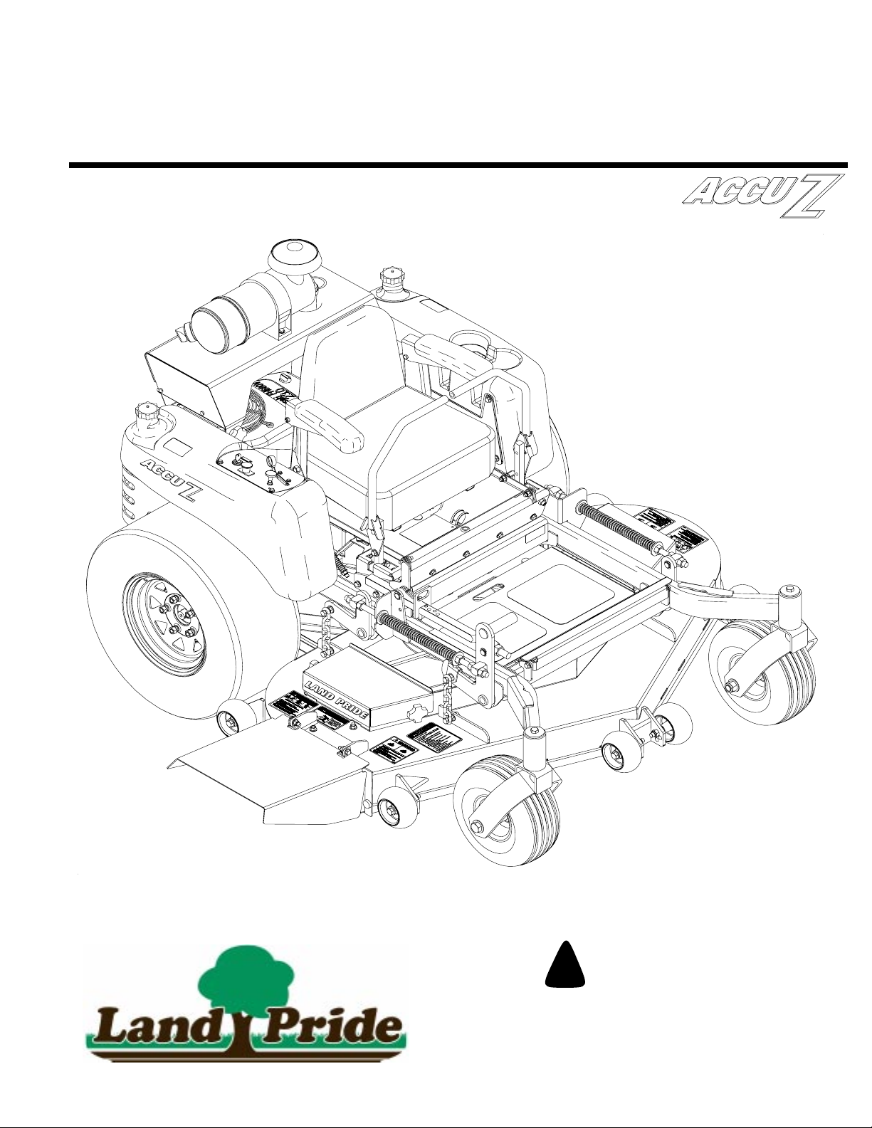
Cover photo may show optional equipment not supplied
with standard unit.
03/11/03
Page 2

Table of Contents
Table of Contents
Land Pride
Important Safety Information . . . . . . . . . . . . . . . . . . .1
Introduction. . . . . . . . . . . . . . . . . . . . . . . . . . . . . . . . . .6
Application . . . . . . . . . . . . . . . . . . . . . . . . . . . . . . . .6
Using This Manual . . . . . . . . . . . . . . . . . . . . . . . . . .6
Terminology. . . . . . . . . . . . . . . . . . . . . . . . . . . . .6
Definitions . . . . . . . . . . . . . . . . . . . . . . . . . . . . . .6
Owner Assistance . . . . . . . . . . . . . . . . . . . . . . . . . .6
Serial Number Plate. . . . . . . . . . . . . . . . . . . . . . . . .6
Further Assistance. . . . . . . . . . . . . . . . . . . . . . . . . .6
Section 1 Assembly and Set-Up . . . . . . . . . . . . . . . . .7
Control Lever and Seat Assembly . . . . . . . . . . . . . .7
Remote Air Cleaner Assembly. . . . . . . . . . . . . . . . .7
Optional Equipment Assemblies . . . . . . . . . . . . . . .8
Remote Air Cleaner Assembly . . . . . . . . . . . . . .8
Control Lever Extensions . . . . . . . . . . . . . . . . . .8
Accu-Vac Assembly. . . . . . . . . . . . . . . . . . . . . . .9
Mower Deck Preparation. . . . . . . . . . . . . . . . . . .9
Blower, Pulley and Pulley Cover Assembly. . . .10
Bagger Assembly . . . . . . . . . . . . . . . . . . . . . . .11
Front Lift and Weight Assembly. . . . . . . . . . . . .12
Section 2 Operation . . . . . . . . . . . . . . . . . . . . . . . . . .13
Controls . . . . . . . . . . . . . . . . . . . . . . . . . . . . . . . . .13
Ignition Switch. . . . . . . . . . . . . . . . . . . . . . . . . .13
Throttle Control . . . . . . . . . . . . . . . . . . . . . . . . .13
Choke Control. . . . . . . . . . . . . . . . . . . . . . . . . .13
Control Levers. . . . . . . . . . . . . . . . . . . . . . . . . .13
Parking Brake. . . . . . . . . . . . . . . . . . . . . . . .14
Deck Clutch Switch. . . . . . . . . . . . . . . . . . . . . .14
Deck Lift Pedal . . . . . . . . . . . . . . . . . . . . . . . . .14
Instrumentation . . . . . . . . . . . . . . . . . . . . . . . . . . .15
Electronic Hour Meter . . . . . . . . . . . . . . . . . . . .15
Oil Pressure Light . . . . . . . . . . . . . . . . . . . . . . .15
Safety Start Interlock System. . . . . . . . . . . . . . . . .15
Engine Starting . . . . . . . . . . . . . . . . . . . . . . . . . . .15
Moving Mower with Stalled Engine . . . . . . . . . . . .16
Driving the Mower . . . . . . . . . . . . . . . . . . . . . . . . .17
Steering. . . . . . . . . . . . . . . . . . . . . . . . . . . . . . .17
To Stop or Decrease Speed . . . . . . . . . . . . . . .17
To Increase Speed . . . . . . . . . . . . . . . . . . . . . .17
Operating Suggestions. . . . . . . . . . . . . . . . . . . . . .17
Mower Deck Operation . . . . . . . . . . . . . . . . . . . . .18
Operating Instructions . . . . . . . . . . . . . . . . . . . . . .19
Section 3 Adjustments. . . . . . . . . . . . . . . . . . . . . . . .20
Torque Values . . . . . . . . . . . . . . . . . . . . . . . . . . . .20
Steering Linkage . . . . . . . . . . . . . . . . . . . . . . . . . .20
Control Lever Neutral Adjustment. . . . . . . . . . .21
Control Lever Stops . . . . . . . . . . . . . . . . . . . . . . . 22
Reverse Spring Adjustment . . . . . . . . . . . . . . . . . 22
Steering Dampener. . . . . . . . . . . . . . . . . . . . . . . . 23
Control Lever Adjustment . . . . . . . . . . . . . . . . . . . 23
Park Brake Adjustment. . . . . . . . . . . . . . . . . . . . . 23
Hydraulic Pump Belt Adjustment . . . . . . . . . . . . . 25
Deck Drive Belt Adjustment . . . . . . . . . . . . . . . . . 25
Engine RPM Setting . . . . . . . . . . . . . . . . . . . . . . . 25
Deck Leveling and Height Adjustment . . . . . . . . . 25
Deck Level Adjustment. . . . . . . . . . . . . . . . . . . 26
Deck Cutting Height Adjustment. . . . . . . . . . . . . . 28
Anti-Scalp Rollers . . . . . . . . . . . . . . . . . . . . . . . . . 29
Section 4 Maintenance and Lubrication . . . . . . . . . 30
Maintenance Locations. . . . . . . . . . . . . . . . . . . . . 30
Maintenance Schedule . . . . . . . . . . . . . . . . . . . . . 31
Maintenance . . . . . . . . . . . . . . . . . . . . . . . . . . . . . 32
Torque Values. . . . . . . . . . . . . . . . . . . . . . . . . . . . 32
Tires . . . . . . . . . . . . . . . . . . . . . . . . . . . . . . . . . . . 32
Hour Meter . . . . . . . . . . . . . . . . . . . . . . . . . . . . . . 33
Lubrication . . . . . . . . . . . . . . . . . . . . . . . . . . . . . . 33
Electrical System . . . . . . . . . . . . . . . . . . . . . . . . . 33
Access to Engine and Hydraulic Pumps. . . . . . . . 34
Hydraulic System . . . . . . . . . . . . . . . . . . . . . . . . . 34
Fuel System . . . . . . . . . . . . . . . . . . . . . . . . . . . . . 35
Engine Oil and Filter . . . . . . . . . . . . . . . . . . . . . . . 35
Engine Air Filter . . . . . . . . . . . . . . . . . . . . . . . . . . 36
Over Service . . . . . . . . . . . . . . . . . . . . . . . . . . 36
ImproperInstallation . . . . . . . . . . . . . . . . . . . . . 36
Damaged Filter, Seals or Canister. . . . . . . . . . 37
Incorrect Air Filter Element. . . . . . . . . . . . . . . . 37
Engine Air Filter Service Procedure . . . . . . . . . . . 37
General Engine Maintenance . . . . . . . . . . . . . . . . 37
Belt Replacement . . . . . . . . . . . . . . . . . . . . . . . . . 38
Mower Blade Maintenance . . . . . . . . . . . . . . . . . . 38
Lift Jack and Weight Option . . . . . . . . . . . . . . . 38
Mower Blade Removal . . . . . . . . . . . . . . . . . . . . . 38
Storage . . . . . . . . . . . . . . . . . . . . . . . . . . . . . . . . . 39
Preparation of Engine for Storage. . . . . . . . . . . . . 39
New Season Preparation . . . . . . . . . . . . . . . . . . . 39
Section 5 Specifications and Capacities. . . . . . . . . 40
Section 6 Features and Benefits . . . . . . . . . . . . . . . 42
Section 7 Troubleshooting . . . . . . . . . . . . . . . . . . . . 43
Section 8 Appendix. . . . . . . . . . . . . . . . . . . . . . . . . . 44
Torque Values Chart for Common Bolt Sizes . . . . 44
Tire Inflation Chart . . . . . . . . . . . . . . . . . . . . . . . . 44
Warranty Statement . . . . . . . . . . . . . . . . . . . . . . . 45
© Copyright 2003 All rights Reserved
LandPrideprovidesthispublication “as is” withoutwarrantyofanykind,either expressed or implied.While every precaution hasbeentaken in thepreparationof this manual,
Land Pride assumes no responsibility for errors or omissions. Neither is any liability assumed fordamages resulting from the use of the information contained herein. Land
Pride reserves the right to revise and improve its products as it sees fit. This publication describes the state of this product at the time of its publication, and may not reflect
the product in the future. The illustrations in this manual are not intended for safe and proper assembly or disassembly of equipment. The illustrations are intended for
ordering parts only.
Land Pride and Accu-Z Razor are registered trademarks.
All other brands and product names are trademarks or registered trademarks of their respective holders.
Printed in the United States of America.
Z52®, Z60® & Z72® Zero Turning Radius Mowers Accu-Z 356-005M
03/11/03
Page 3
Land Pride
▲
Important Safety Information
Important Safety Information
These are common practices that may or may not be applicable to the products described in
this manual.
Be Aware of Signal Words
A signal word designates a degree or
level of hazard seriousness. The
signal words are:
!
DANGER!
Indicates an imminently hazardous
situation which, if not avoided, will
result in death or serious injury. This
signal word is limited to the most
extreme situations, typically for
machine components that, for
functional purposes, cannot be
guarded.
!
WARNING!
Indicates a potentially hazardous
situation which, if not avoided, could
result in death or serious injury, and
includes hazards that are exposed
when guards are removed. It may
also be used to alert against unsafe
practices.
!
CAUTION!
Indicates a potentially hazardous
situation which, if not avoided, may
result in minor or moderate injury. It
may also be used to alert against
unsafe practices.
!
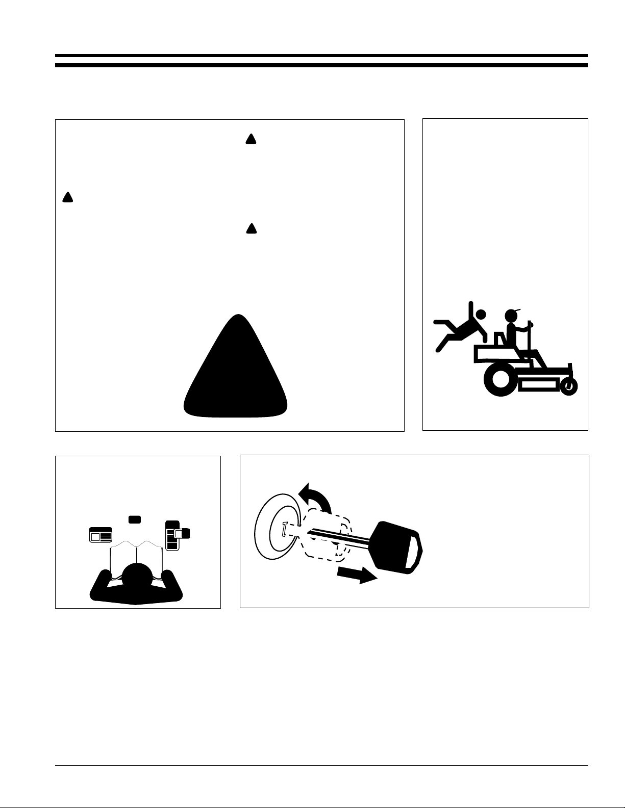
Keep Riders
Off Machinery
▲ Riders obstruct the operator’s
view, they could be struck by
foreign objects or thrown from the
machine.
▲ Never allow children to operate
equipment.
For Your Protection
▲ Thoroughly read and understand
the “Safety Label” section, read all
instructions noted on them.
OFF
Shutdown and Storage
▲ Put mower in park, turn off
engine, and remove the key.
▲ Store in an area where children
normally do not play.
ON
03/11/03
Z52®, Z60® & Z72® Zero Turning Radius Mowers Accu-Z 356-005M
1
Page 4
Land Pride
Important Safety Information
These are common practices that may or may not be applicable to the products described in
this manual.
Practice Safe Maintenance
▲ Understand procedure before
doing work. Use proper tools and
equipment, refer to Operator’s
Manual for additional information.
▲ Work in a clean dry area.
▲ Do not grease or oil while in
operation.
▲ Inspect all parts. Make sure parts
are in good condition & installed
properly.
▲ Remove buildup of grease, oil or
debris.
▲ Remove all tools and unused
parts before operation.
Safety at All Times
Thoroughly read and understand the
instructions given in this manual
beforeoperation. Refer to the “Safety
Label” section, read all instructions
noted on them.
▲ Operator should be familiar with
all functions of the unit.
▲ Operate mower from the driver’s
seat only.
▲ Do not leave mower unattended
with engine running.
▲ Dismounting from a moving
mower could cause serious injury
or death.
▲ Keep hands, feet, and clothing
away from power-driven parts.
▲ Wear snug fitting clothing to avoid
entanglement with moving parts.
▲ Make sure all persons are clear of
working area.
Z52®, Z60® & Z72® Zero Turning Radius Mowers Accu-Z 356-005M 03/11/03
2
Page 5
Land Pride
Important Safety Information
These are common practices that may or may not be applicable to the products described in
this manual.
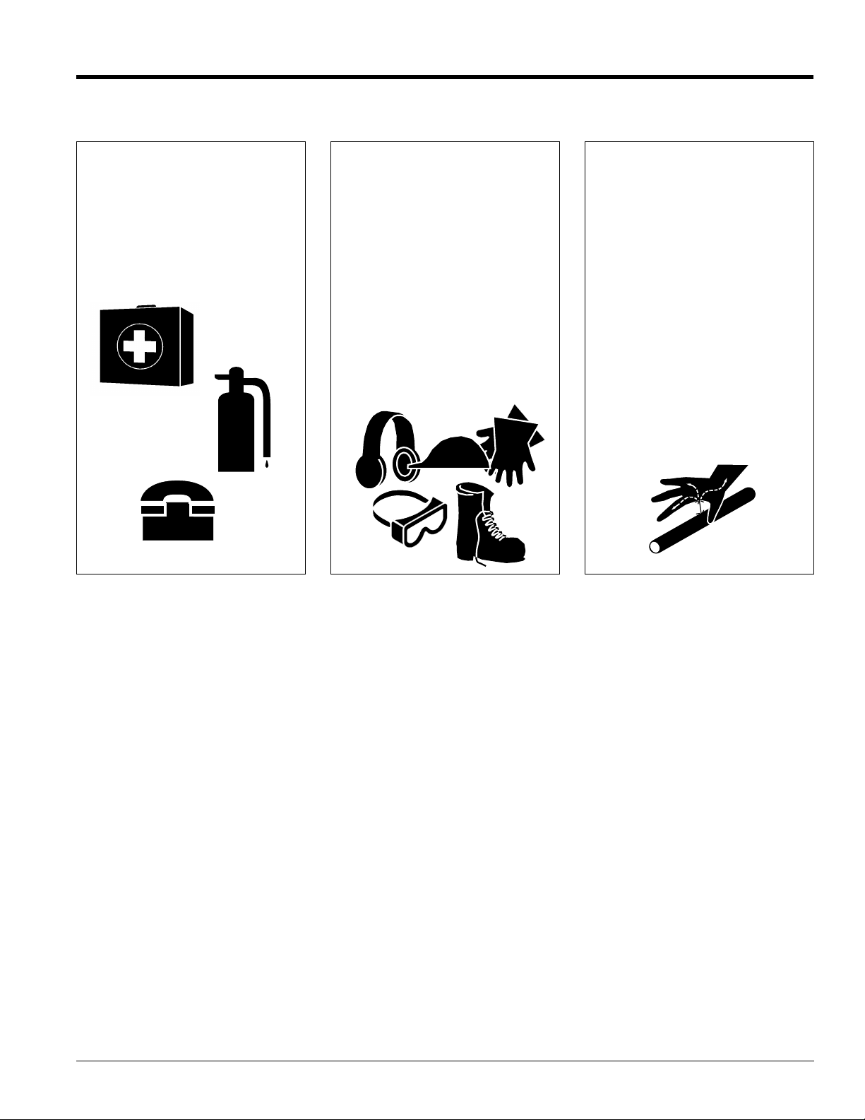
Prepare for Emergencies
▲ Be prepared if a fire starts.
▲ Keep a first aid kit and fire
extinguisher handy.
▲ Keep emergency numbers for
doctor, ambulance, hospital and
fire department near phone.
911
Wear
Protective Equipment
▲ Protective clothingand equipment
should be worn.
▲ Wear clothing and equipment
appropriate for the job. Avoid
loose fitting clothing.
▲ Prolonged exposure to loud noise
can cause hearing impairment or
hearing loss. Wear suitable
hearing protection such as
earmuffs or earplugs.
▲ Operating equipment safely
requires the full attention of the
operator. Avoid wearing radio
headphones while operating
machinery.
Avoid High
Pressure Fluids Hazard
▲ Escaping fluid under pressure can
penetratethe skin causing serious
injury.
▲ Avoid the hazard by relieving
pressure before disconnecting
hydraulic lines.
▲ Use a piece of paper or
cardboard, NOTBODYPARTS, to
check for suspected leaks.
▲ Wear protective gloves and safety
glasses or goggles when working
with hydraulic systems.
▲ If an accident occurs, see a
doctor immediately. Any fluid
injected into the skin must be
surgically removed within a few
hours or gangrene may result.
Safety Labels
1. Your mower comes equipped with all safety labels in place.
They were designed to help you safely operate your mower.
Read and follow their directions.
2. Keep all safety labels clean and legible.
3. Replace all damaged or missing labels. To order new labels
go to your Land Pride dealer.
4. Some new equipment installed during repair require safety
labels to be affixed to the replaced component as specified
by Land Pride. When ordering new components make sure
03/11/03
Z52®, Z60® & Z72® Zero Turning Radius Mowers Accu-Z 356-005M
the correct safety labels are included in the request. To
order new labels go to your Land Pride dealer.
5. Refer to this section for proper label placement.
To install new labels:
a. Clean the area the label is to be placed.
b. Spray soapy water on the surface where the label is to
be placed.
c. Peel backing from label. Press firmly onto the surface.
d. Squeeze out air bubbles with the edge of a credit card.
3
Page 6
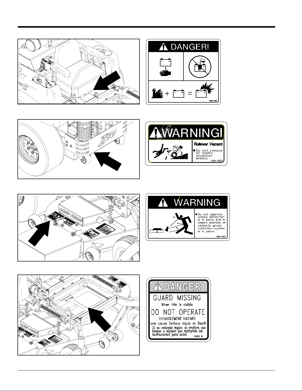
Important Safety Information
19097
Land Pride
838-303C
Danger: Battery
(Beneath Seat)
19097
19098
838-305C
Warning:Rollover Hazard(Beneath Bumper on Back ofFrame)
838-306C
Warning: Do not operate without deflector
19097
Z52®, Z60® & Z72® Zero Turning Radius Mowers Accu-Z 356-005M 03/11/03
4
818-543C
Danger: Guard is missing
(Beneath foot pan on mower deck)
Page 7
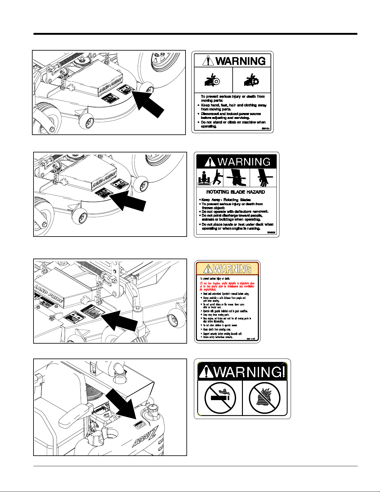
Land Pride
Important Safety Information
19057
838-307C
Warning: Moving Parts
(Both Sides)
19057
19097
838-308C
Warning: Rotating Blade
Hazard (Both Sides)
838-310C
Warning: General
03/11/03
838-399C
19057
Z52®, Z60® & Z72® Zero Turning Radius Mowers Accu-Z 356-005M
Warning: Fuel
Imbedded in Fuel Tank
5
Page 8
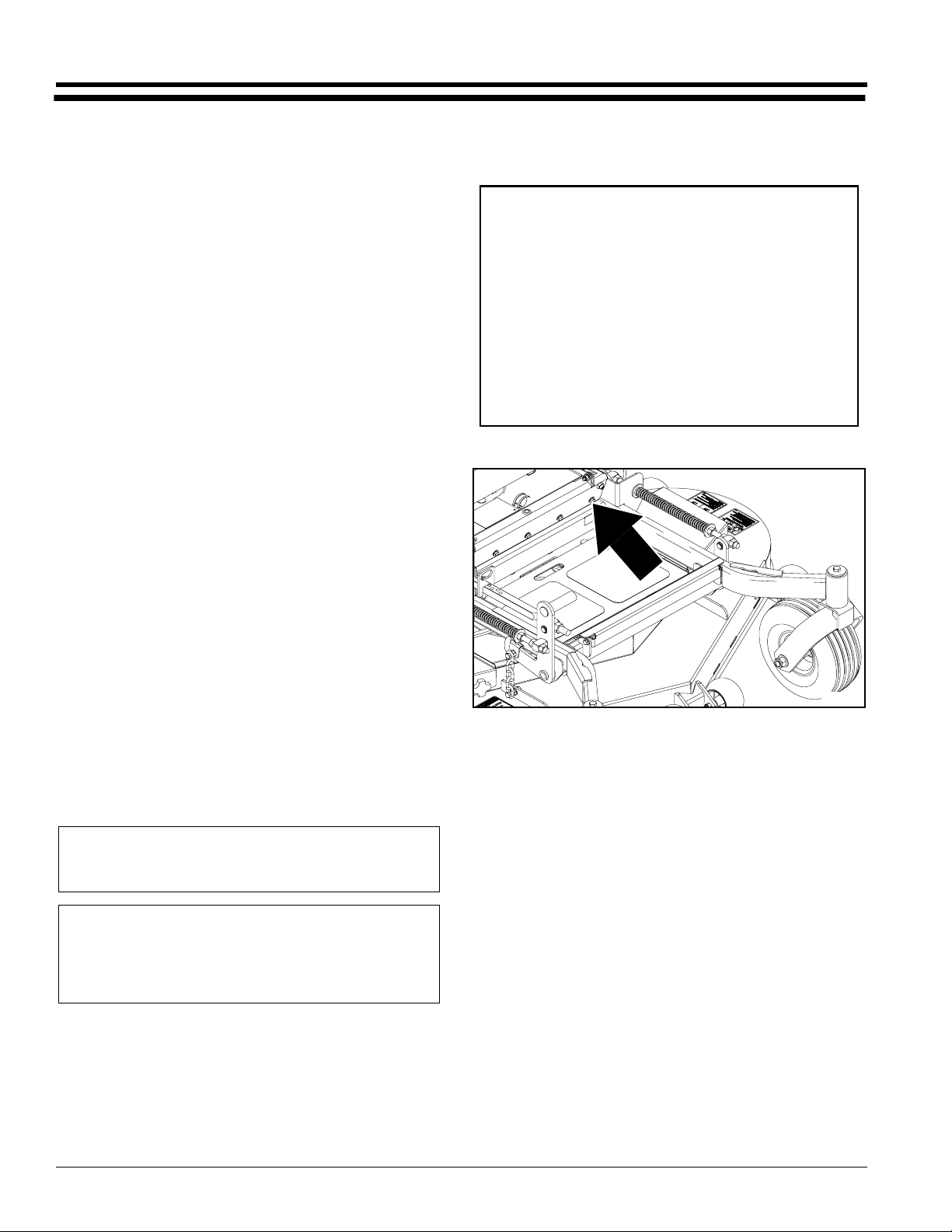
Introduction
Introduction
Land Pride
Land Pride welcomes you to the growing family of new
product owners.
This mower has been designed with care and built by
skilled workers using quality materials. Proper assembly,
maintenance, and safe operating practices will help you
get years of satisfactory use from the machine.
Application
The Accu-Z Razor®mowers from Land Pride are compact
in size and ideal for homeowner and commercial grass
maintenance . The Accu-Z is a true zero-turn mower:
When mowing alongside a building or landscaping, the
Accu-Z turns within its own width, allowing you to turn
away and not hit anything with the rear end. This makes it
the perfect choice for cemeteries, parks, recreational
areas, sports fields and schools where obstacles are
prevalent. An optional Vacuum Bagger, Mulching Kit and
Control Lever Extensions are also available. See
“Features and Benefits”, “Section 6” for additional
information.
Using This Manual
• This Operator’s Manual is designed to help familiarize
you with safety, assembly, operation, adjustments,
troubleshooting, and maintenance. Read this manual
and follow the recommendations to help ensure safe
and efficient operation.
• The information contained within this manual was
current at the time of printing. Some parts may change
slightly to assure you of the best performance.
• To order a new Operator or Parts Manual contact your
authorized dealer. Manuals can also be downloaded,
free-of-charge from our website at www.landpride.com
or printed by your dealer from the Land Pride Service &
Support Center CD-Rom.
Terminology:
“Right” or “Left” as used in this manual is determined by
facing the direction the machine will operate while in use
unless otherwise stated.
Definitions:
NOTE:A special point of information that the operator
must be aware of before continuing.
IMPORTANT: A special point of inf ormation related to
its preceding topic. Land Pride’s intention is that this
information should be read and noted before
continuing.
The parts on your Accu-Z Mower have been specially
designed and should only be replaced with genuine Land
Pride parts. Therefore, should your Accu-Z require
replacement parts go to your Land Pride Dealer.
IMPORTANT:
For parts and service for your engine contact your
nearest dealer or Call Customer Service Hotline.
Honda Engine Information:
Service Manual: P/N 61ZJ410Z
Owner’s Manual: P/N 31ZJ4620
Service Hotline: 1-770-497-6400
Kawasaki Engine Information:
Service Manual: P/N 99924-2045-02
Owner’s Manual: P/N 99920-2145-02
Service Hotline: 1-800-433-5640
Serial Number
Referto theFigure 1for thelocation ofyour serial number.
19097
Serial Number Location
Figure 1
Further Assistance
Your dealer wants you to be satisfied with your new
mower.If forany reason youdo notunderstand anypart of
this manual or are not satisfied with the service received,
the following actions are suggested:
1. Discussthe matter with your dealership service
managermaking sure he isaware ofany problemsyou
mayhaveand that he has had the opportunity to assist
you.
2. If you are still not satisfied, seek out the owner or
general manager of the dealership, explain the
problem and request assistance.
3. For further assistance write or E-mail to:
Owner Assistance
The Warranty Registration card should be filled out by the
dealer at the time of purchase. This information is
necessary to provide you with quality customer service.
If customer service or repair parts are required contact a
Land Pride dealer. A dealer has trained personnel, repair
parts and equipment needed to service the implement.
Z52®, Z60® & Z72® Zero Turning Radius Mowers Accu-Z 356-005M 03/11/03
6
Land Pride
Service Department
P.O. Box 5060
Salina, KS 674022-5060
E-mail address
Page 9
Land Pride
Section 1 Assembly and Set-Up
Section 1
Assembly and Set-Up
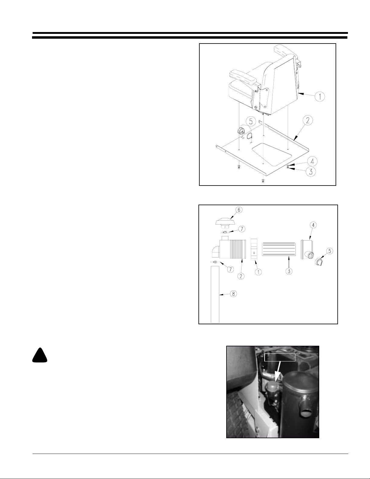
Control Lever and Seat Assembly
The seat is removed for ease in shipping and the control
lever’s upper bolts and flat washers are removed and the
levers are rotated down.
Refer to Figure 1-1:
1. Install the standard seat (#1) (or the optional
suspension seat) to the seat pan (#2) using four 5/16”
nuts (#3) and four 5/16” flat washers (#4).
2. Connecttheswitchwires onthe mower withtheswitch
wires on the seat. Secure the switchwires to the seat
pan (#2) using three wire ties (#5).
3. Fliptheseat overinto theoperatingposition androtate
thecontrol leversup untilthe holesline upand replace
the bolts and flat washers.
Remote Air Cleaner Assembly
Refer to Figure 1-2:
1. Slide air cleaner clamp (#1) over air cleaner housing
(#2), position the clamp so the bolt holes are facing
down (away from the intake) and the notches on the
clamp fit in the notches on the housing.
2. Insert air cleaner element (#3) inside air cleaner
housing (#2) and attach housing end (#4) (with the
arrows pointing up). Place rubber grommet (#5) over
opening in housing end (#4).
3. Attach air cleaner intake cap (#6) to the air cleaner
housing (#2) using a hose clamp (#7).
4. Attach air cleaner hose (#8) to the air cleaner (#2)
using a hose clamp (#7).
20858
Seat Assembly
Figure 1-1
Refer To Figure 1-3:
5. Remove plastic cap from carburetor intake.
!
CAUTION!
Be careful to not allow any foreign material into the carburetor
while performing this assembly.
03/11/03
20862
Air Cleaner Assembly
Figure 1-2
Plastic Cap
20859
Carburetor Intake
Figure 1-3
Z52®, Z60® & Z72® Zero Turning Radius Mowers Accu-Z 356-005M
7
Page 10
Section 1 Assembly and Set-Up
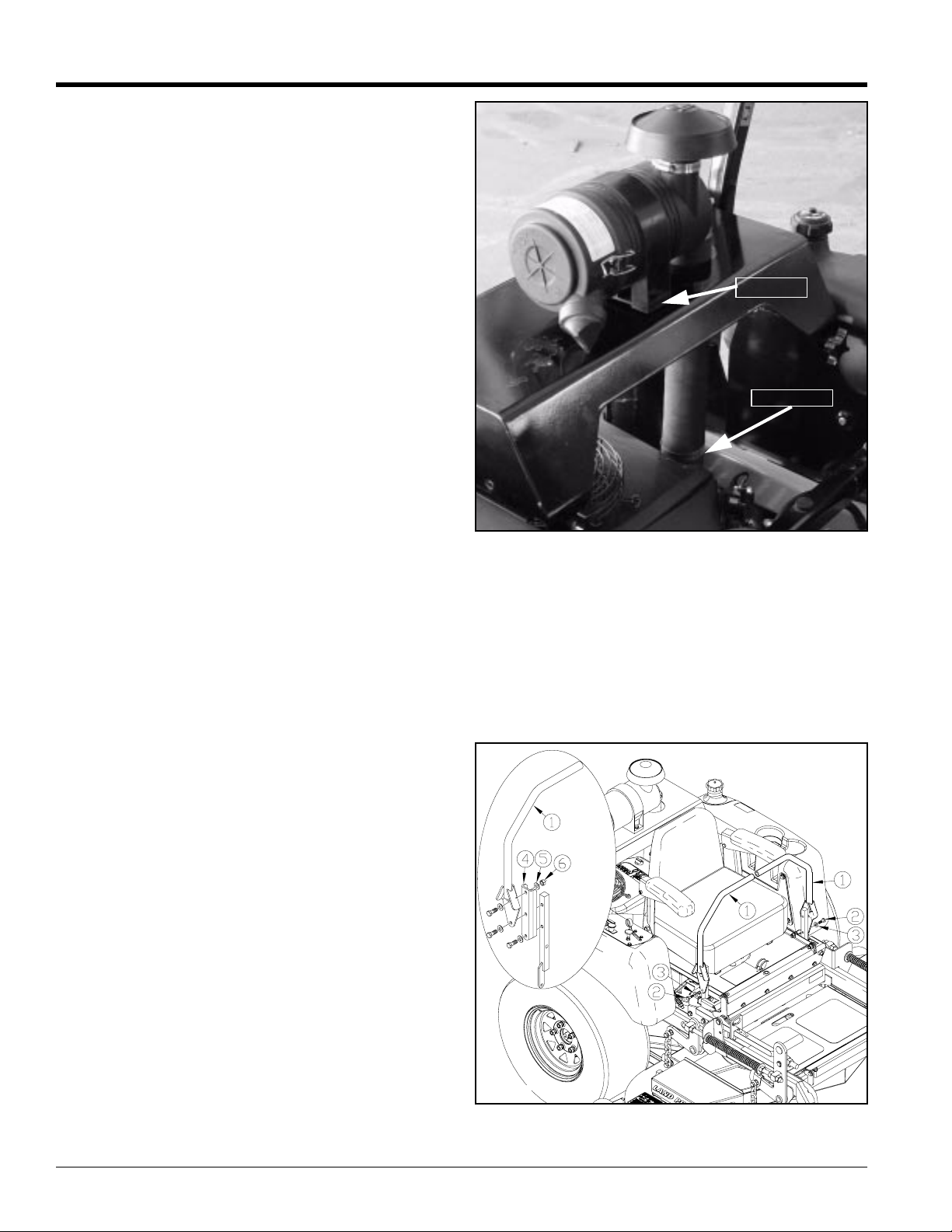
Refer to Figure 1-4:
6. Insert the air cleaner hose through the hole in the air
cleaner hood and slide hose end over the carburetor
intake.
7. Secure air cleaner to the air cleaner hood with two 5/
16” bolts, four 5/16” flat washers and two 5/16” nuts.
8. Securehose to thecarburetor intakewith hoseclamp.
Land Pride
5/16” Bolt
Hose Clamp
Optional Equipment Assemblies
Remote Air Cleaner Assembly
Refer to Figure 1-2 page 7:
The remote air cleaner is standard equipment on mowers
with Serial No. 364548 and above.
However, it may be purchased as an option on mowers
with Serial No. 364547 and below.
Control Lever Extensions
Refer to Figure 1-5:
1. Install the Extensions (#4) as shown.
20860
Figure 1-4
Air Cleaner
19121
Control Lever Assembly
Figure 1-5
Z52®, Z60® & Z72® Zero Turning Radius Mowers Accu-Z 356-005M 03/11/03
8
Page 11
Land Pride
Section 1 Assembly and Set-Up
Accu-Vac Assembly
Refer to Figure 1-9 on page 12
Land Pride offers as an option an Accu-Vac Collection
System designed to collect mower clippings into two 30
gallon rubber containers mounted on the back of the
mower.
NOTE: Accu-Vac Collection System cannot be
mounted on Accu-Z mowers manufactured with
Honda engines. Use only with Kawasaki engines.
!
WARNING!
Do not operate Accu-Vac System without remote air cleaner setup or engine damage may occur.
!
WARNING!
Do not operate mower without deflector chute or Accu-Vac in
place.
Mower Deck Preparation
Refer to Figure 1-6:
Park the Accu-Z mower on a flat surface. Shut off the
ignition switch and remove the key from the switch.
Disconnect the negative battery cable.
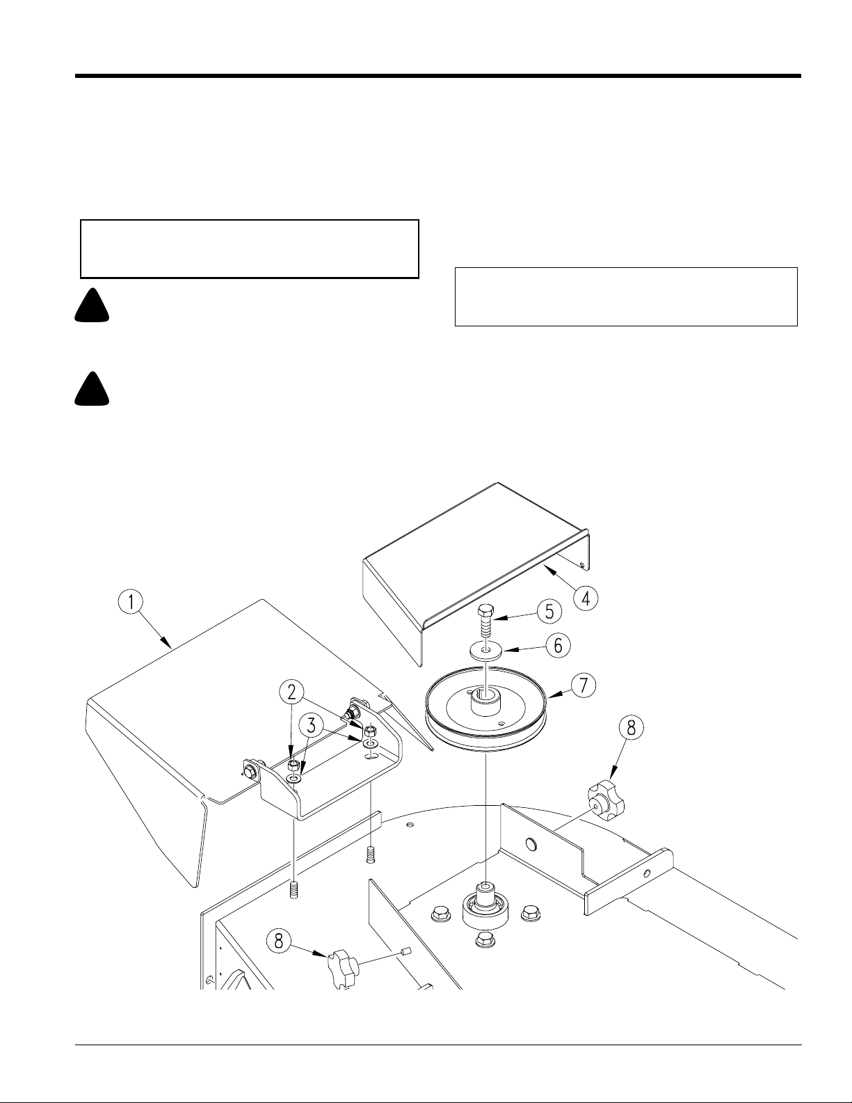
Beforethe Accu-Vaccan be installed, the right side pulley
cover (4) and discharge chute assembly (1) must be
removed. Loosen the tensioner for the blade belt and
remove pulley (7). Parts 2, 3, 6 and 8 will be used to
assemble Accu-Vac.
NOTE:Retainall other partsas theywillbe re-installed
when the Accu-Vac is removed.
19907
03/11/03
Chute, Pulley and Pulley Cover Removal
Figure 1-6
Z52®, Z60® & Z72® Zero Turning Radius Mowers Accu-Z 356-005M
9
Page 12
Section 1 Assembly and Set-Up
Land Pride
Blower, Pulley and Pulley Cover Assembly
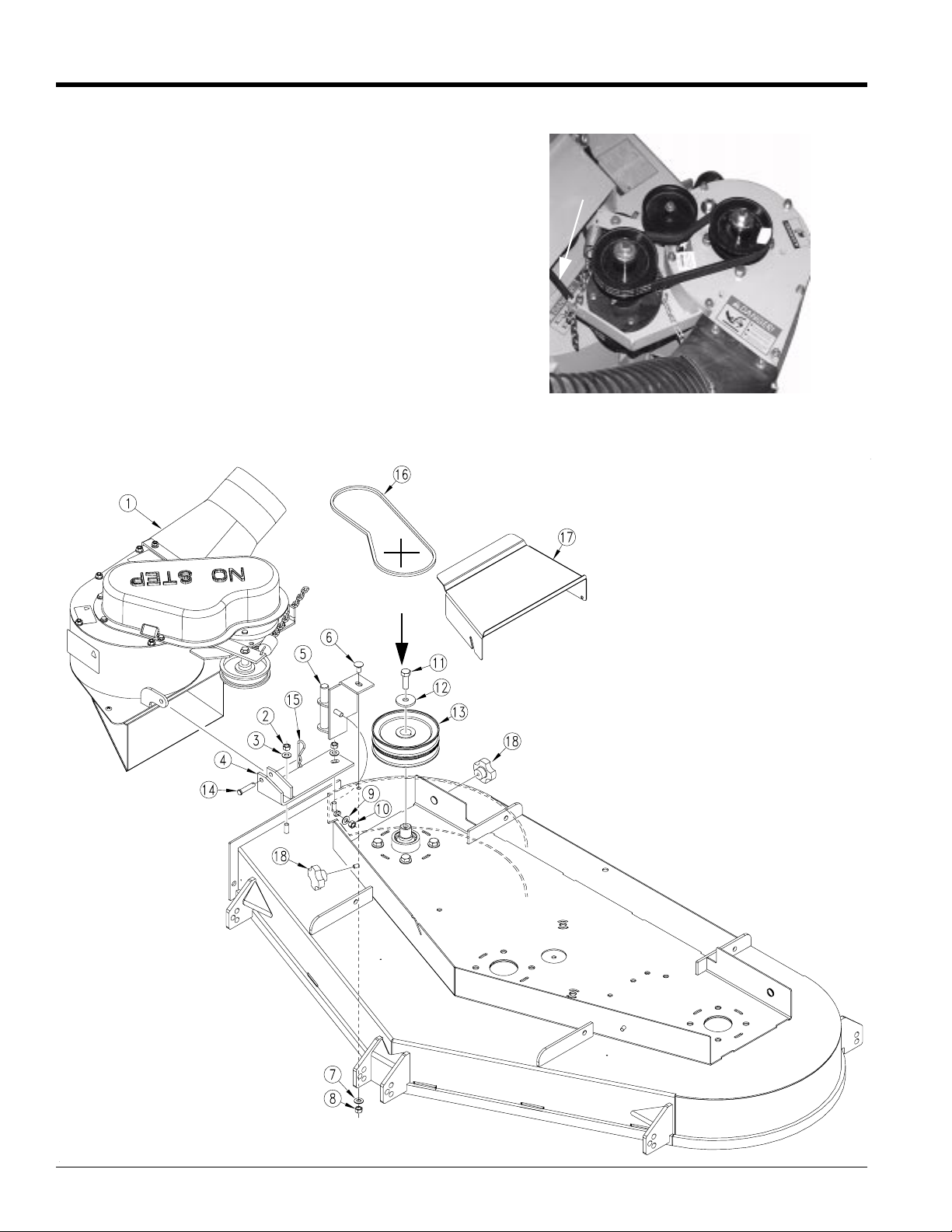
Refer to Figure 1-7:
1. Install double pulley (#13) with the bolt (#11) and
existing flat washer (#12) Torque bolt 65 - 75 lbs.
2. Reinstall blade drive belt on lower grove of pulley
(13).
3. Assemble bracket (#4) where the chute bracket was
assembled using the existing hardware (#2) and
(#3).
4. Assemble blower pivot (#5) with carriage bolt (#6)
and existing hardware (#7), (#8), (#9) and (#10).
5. Install blower (#1) on blower pivot and swing blower
around and secure to bracket with pin (#14) and hair
pin cotter (#15).
6. Install blower belt (#16) to double pulley and route it
as shown. (Belt must be on top pulley)
Blower
Drive Belt
20855
Blower Belt
7. Assemble pulley cover (#17) using existing knobs
(#18).
Route Beltto
TopPulley
Blower Assembly
Figure 1-7
Z52®, Z60® & Z72® Zero Turning Radius Mowers Accu-Z 356-005M 03/11/03
10
Page 13
Land Pride
Section 1 Assembly and Set-Up
Bagger Assembly
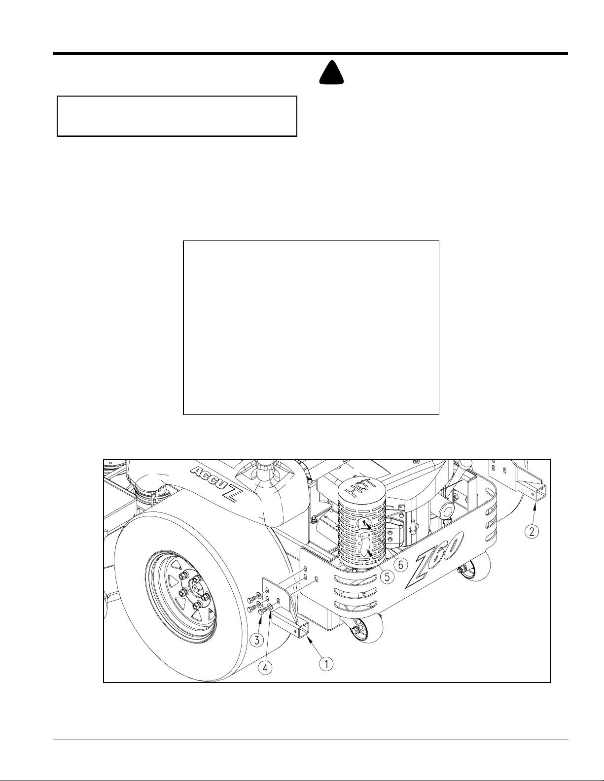
Refer to Figure 1-8:
NOTE: Accu-Vac Collection System cannot be
mounted on Accu-Z mowers manufactured with
Honda engines. Use only with Kawasaki engines.
1. Remove and retain rear bumper bolts (#3) and flat
washers (#4). Do not remove bumper.
2. Assemble left bracket (#1) and right bracket (#2)
through the same slots using the bolts and flat
washers retained from the bumper.
Damage will occur if:
Failure to install and/or adjust muffler exhaust deflector,
will result in damage to either grass catcher container or
mower.
With engine cool:
Install the muffler exhaust deflector onto current muffler
exhaust pipe.
Swivel deflector around so the exhaust is porting away
fromboth unit andbagger.Start mower and check air flow
out of deflector. Make sure hot exhaust air is not diverted
onto unit or bagger. Exhaust should be diverted out to
side.
Mark muffler exhaust pipe using hole in diverter.
Drill muffler exhaust pipe using #26 (.147) drill bit.
Muffler can cause burning. Muffler should be cool before proceeding.
3. Position muffler deflector (#5) on existing muffler
4. Install muffler deflector to existing exhaustand fasten
Important
!
CAUTION!
exhaust so that deflector is pointing away from the
plasticcontainers.Mark forholethroughdeflector (#5)
and drill hole for screw using a #26 (.147) drill bit.
with screw (#6) through hole in deflector and drilled
hole.
03/11/03
Bagger Brackets and Muffler Deflector Assembly
Figure 1-8
Z52®, Z60® & Z72® Zero Turning Radius Mowers Accu-Z 356-005M
19910
11
Page 14
Section 1 Assembly and Set-Up
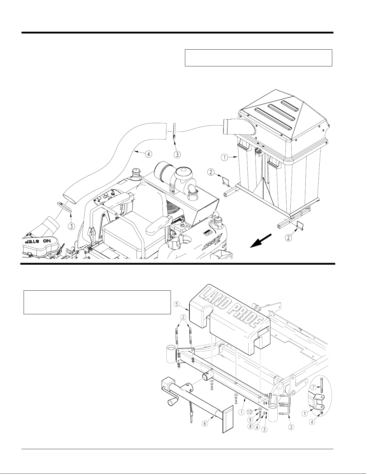
5. Install bagger (#1) through brackets and secure with
pins (#2).
6. Assembleclamps (#3) on the ends of the bagger tube
(#4) and slide the tube over the bagger inlet and the
blower as shown in Figure 1-9 and tighten clamps.
Bagger Assembly
Figure 1-9
Land Pride
NOTE: Lubricant can be used when installing tube to
bagger so the tube will slide over bagger inlet easier.
Front Lift and Weight Assembly
(For Blade Service or Replacement)
IMPORTANT:Do not use jack to support mower while
working under the deck. Chock back wheels and
securely block unit up before working under the deck.
1. The front weight bracket(#1) will mount to the front of
the mower frame with the four u-bolts (#2) lock
washers(#3) and nuts (#4) onthe Z60 & Z72 mowers.
TheZ52 mounts with twou-bolts (#2) onthe right side
and one bolt (#7) and nut (#4) on the left side of
frame as shown in Figure 1-10.
2. Fill the weight (#5) with sand and secure to
weight bracket with bolts (#8), lock washers (#9)
and flat washers (#10).
3. Assemble jack (#6) to the jack mount on the
weight bracket.
19911
Front Lift and Weight Assembly
Figure 1-10
Z52®, Z60® & Z72® Zero Turning Radius Mowers Accu-Z 356-005M 03/11/03
12
Z52 Left Side
19909
Page 15
Land Pride
Section 2 Operation
Section 2
Operation
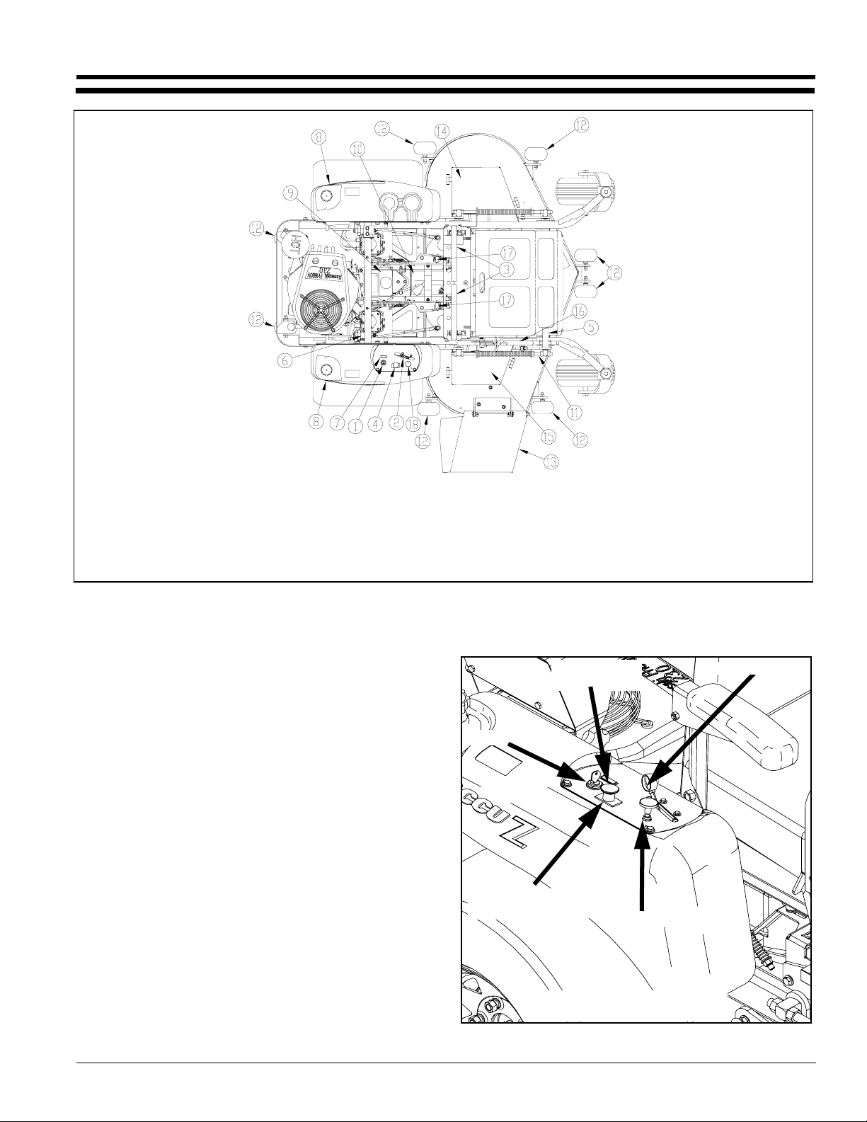
19058
1. Ignition Switch
2. Throttle Lever
3. Control Levers
4. Blade Engagement
Switch
5. Deck Lift Pedal
6. Hour Meter
7. Oil Pressure Light
8. Fuel Tanks
9. Hydraulic Reservoir
Accu Z Controls
Figure 2-1
Controls
For general location of the controls described in this
section, refer to Figure 2-1.
Ignition Switch
Refer to Figure 2-2:
A three position switch: off, run, and start. With key
inserted, rotate it clockwise to START position; release
key when engine starts, and switch will automatically
return to the RUN position.
Throttle Control
Refer to Figure 2-2:
A cable is linked to engine throttle for controlling engine
speed. Move lever forward to increase engine rpm, move
lever rearward to decrease engine rpm.
Choke Control
Refer to Figure 2-2:
A cable is linked to manually operate the engine choke.
When the lever is in the down position, the choke is in the
off(run) position. When the leveris pulled up, the choke is
in the on (start) position. DO NOT operate the machine in
the on (start) position.
10. Battery
11. Deck Adjusting Rod
12. Anti-Scalp Wheels
13. Discharge Chute
14. Left Belt/Pulley Cover
Oil Pressure
Light
Ignition Switch
Blade Engagement
Switch
19097
Control Panel
15. Right Belt/PulleyCover
16. Deck Height Indicator
17. Brake Switch
18. Choke Lever
Throttle
Choke
Figure 2-2
03/11/03
Z52®, Z60® & Z72® Zero Turning Radius Mowers Accu-Z 356-005M
13
Page 16
Section 2 Operation
Land Pride
Left/Right Fuel Tank Valve
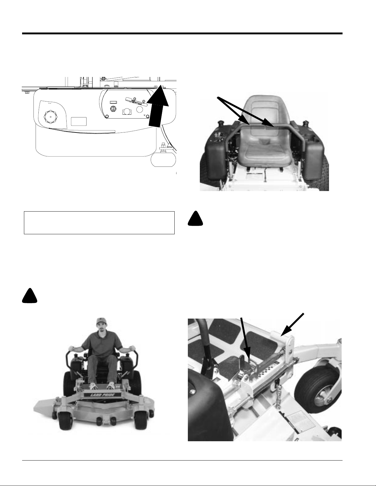
Refer to Figure 2-3:
The mower is equipped with a Left/Right Fuel Tank Valve
that will determine which fuel tank the mower is operating
from.It is not important which fuel tankthe mower isusing.
Left/Right Fuel Tank Switch
Figure 2-3
Blade Engagement Switch
Refer to Figure 2-2:
Thisswitch engages the deck blades. Pull the switchup to
engage and push switch down to disengage the clutch.
IMPORTANT:Never engage clutch with engine
running at high rpm or when the deck is under load.
Clutch, belts or deck could be damaged.
Control Levers
Parking Brake
The Parking Brakes are applied by moving the control
leversfrom theNeutral Position(Figure 2-5)to anoutward
position (Refer to Figure 2-4). Each rear wheel brake
operates independently of the other.
!
WARNING!
In the event of a system failure while mowing, engage both
parking brakes to stop or slow mower. Refer to Figure 2-4.
Refer to Figure 2-5:
Theselevers controlthe mower’sspeed, direction,neutral
lock and park brake. Levers are used to steer, accelerate,
brake and change direction. The mower will not move
when the engine is on, drive pumps are operating and the
control levers are in the park brake position (out)
Figure 2-4.
Control Levers
Control Levers
Figure 2-5
!
WARNING!
The parking brake is not designed to hold the mower on steep
slopes.
Deck Lift Pedal
Refer to Figure 2-6:
Thedeck lift pedal isused to raise orlower the deck. Push
on the pedal to raise the deck and then place the deck
height locking pin into the desired cutting height hole.
Push the deck lift pedal to raise the deck when going over
obstructions.
Deck Height
Locking Pin
19060
Deck Lift
Pedal
Control Levers in Parking Brake Position
Figure 2-4
Z52®, Z60® & Z72® Zero Turning Radius Mowers Accu-Z 356-005M 03/11/03
14
19698
Deck Lift Pedal
Figure 2-6
19061
Page 17
Land Pride
Section 2 Operation
Instrumentation
Electronic Hour Meter
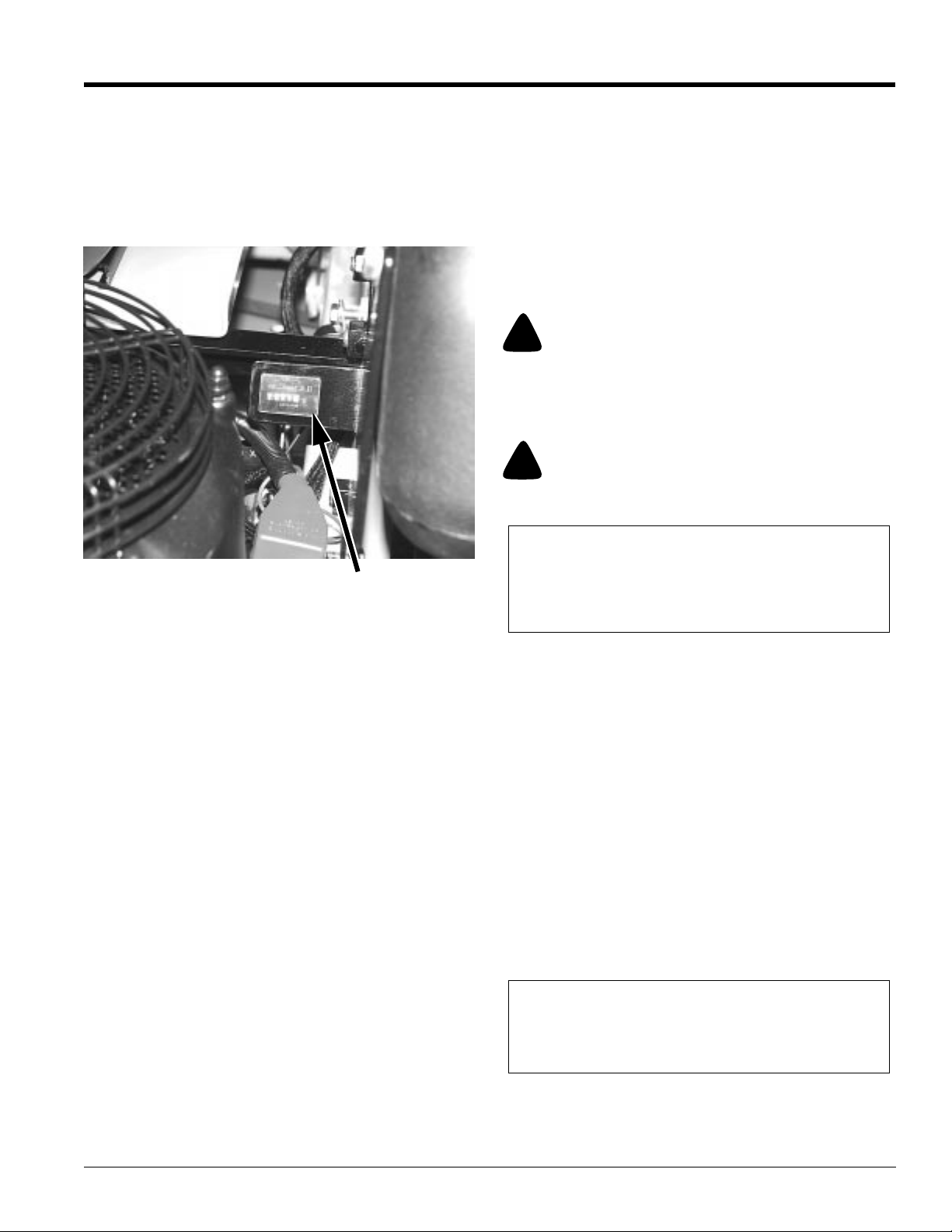
Refer to Figure 2-7:
Registers 1/10 hour increments up to 9,999.9 total hours.
Connected to the ignition switch, the meter records the
accumulative time while the ignition key is switched to the
RUN position and the operator is on the seat.
19062
Hour Meter
Hour Meter
Figure 2-7
Oil Pressure Light
Refer to Figure 2-2:
This light comes on when the ignition switch is placed in
the RUN position and stays lit until the engine is running
and a safe oil pressure is developed. If light comes on
during operation, shut engine off immediately and locate
and correct the problem.
Safety Start Interlock System
Themoweris equippedwith a safetystart interlocksystem
consisting of the brake switches, seat switch, and deck
clutch switch. Check mower safety start interlock system
daily, prior to operation. This system is an important
mower safety feature. It should be repaired immediately if
itmalfunctions. The machineincorporates aseparate seat
switch which will stop the mower engine when the
operator is unseated for any reason while the mower is
moving or the deck clutch is engaged. This is a safety
feature designed to prevent runaway or accidental
entanglement. To inspect the system:
1. The operator must be on the seat when testing the
seat switch.
2. Set both control levers in the park brake position.
3. Start the engine and allow it to warm up to operating
temperature.
4. With the deck clutch switch down and the control
leversinthe park brakeposition, slowly raise off of the
seat. The engine should continue to run.
5. With the deck clutch switch up and/or the control
leversin the neutral position, slowly raise off of the
seat. The engine should stop within two seconds.
6. If the engine failsto stop when the deck clutch switch
is up or one or both of the control leversis in and the
operator is off the seat, check the function of the seat
switch.If the seat switch is not operating properly and
if the cause can not be determined, replace the seat
switch.
Ifthe problem can not be located, contact your LandPride
Dealer.
!
WARNING!
The safety interlock system should always function per steps 4
and 5. If it does not function properly, it should be corrected
immediately. Do not operate the mower without a properly
functioning seat safety switch.
!
WARNING!
The safety interlock system must not be disconnected or
bypassed.
NOTE: The operator’s seat is equipped with a
separate safety switch. If for any reason the operator
should become unseated when the neutral switches
are disengaged or the deck clutch switchis engaged
the engine will stop.
Engine Starting
The Accu Z safety start interlock system is also designed
to protect the operator and others from accidental injury
due to unintentional engine starting. The engine starting
motor will not engage until:
A. Control levers are in the brake position.
B. Deck clutch switch is in the down (OFF) position.
Thefollowing steps are thecorrect procedures for starting
the engine. If difficulty is encountered, contact the Land
Pride Dealer in your area.
1. Before starting mower each day, perform daily preoperation checking.
2. Make sure the control leversare in the brake position
and deck clutch switch is disengaged.
3. Set throttle at approximately 1/2 open position.
NOTE: Use choke position when engine is cold, or if
warm engine fails to start within 5 seconds of
cranking. Avoid flooding and operate engine without
choking as soon as possible.
4. Insert keyin ignition switch and rotate full clockwiseto
engage starting motor. Release keywhen engine
starts.
03/11/03
Z52®, Z60® & Z72® Zero Turning Radius Mowers Accu-Z 356-005M
15
Page 18
Section 2 Operation
IMPORTANT:The engine starter should not be
operatedfor periods longerthen 30 seconds ata time.
An interval of at least two minutes should be allowed
between such cranking periods to protect the starter
from overheating and burn-out.
5. Performtestto make sure safetystart interlocksystem
is operating properly. Refer to Safety start interlock
system section.
6. As soon as engine begins to run, check to make
certain the oil warning light is off. If not, stop engine
immediately and check for the cause.
7. Allow the engine to idle a few minutes before
advancing the throttle and/or engaging the deck
clutch.
8. Beforestopping the engine, place the controlleversin
the brake position, disengage the deck clutch, and
throttle back to low idle for a couple of minutes; then
rotate ignition key counter-clockwise to the OFF
position. Remove the key from switch before leaving
the seat.
!
WARNING!
Never leave the machine unattended with key in ignition switch.
Moving Mower with Stalled Engine
If it becomes necessary to move the mower when the
engine is inoperative, the hydraulic pumps are equipped
with bypass valves. Before moving the unit, turn bypass
valves counter clockwise one-half to one revolution. The
valve stems on each hydraulic pump are located near the
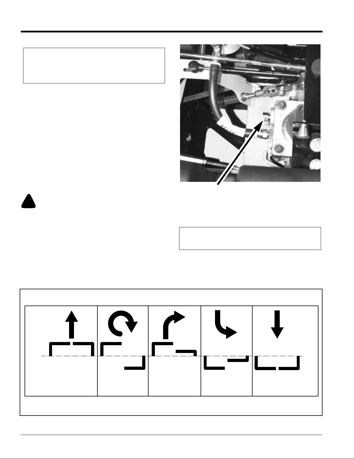
top and are identified as a hex stud. Refer to Figure 2-8.
Land Pride
Bypass
Valve
Donot tow themachine. Move it byhand or usea winch to
load on a trailer for transporting.
IMPORTANT: Always make certain the two bypass
valves are returned to their operating position before
running the mower following repairs.
Bypass Valve
Figure 2-8
19064
Front of mower Faces This Direction
N
Forward Travel Pivot Right Turn Forward Travel
Right Turn
N= Neutral Position
Direction of arrows indicate direction of mower movement.
Steering
Figure 2-9
Z52®, Z60® & Z72® Zero Turning Radius Mowers Accu-Z 356-005M 03/11/03
16
Reverse Travel
Right Turn
Reverse Travel
N
Page 19

Land Pride
Section 2 Operation
Driving the Mower
!
DANGER!
Never make sudden stops or reverse direction, especially when
going down a slope. The steering is designed for sensitive
response. Rapid movement of the control levers in either
directioncould result in a reaction of the mower that can cause
serious injury.
Steering
Refer to Figure 2-9:
After starting engine, engage the control levers and steer
as follows:
To Go Forward:
Push control levers forward an equal distance.
To Go in Reverse:
Pull control levers rearward an equal distance.
To Turn Left:
Move the right control lever farther forward from neutral
than the left control lever.
To Turn Right:
Move the left control lever farther forward from neutral
than the right control lever.
To Pivot Turn:
Moveone control lever forwardand the other control lever
back of neutral, this will allow the drive wheels to counterrotate.
To Stop or Decrease Speed
!
WARNING!
In the event of a system failure while mowing, engage both
parking brakes to stop or slow mower. Refer to Figure 2-4.
Move control levers to neutral. When going forward pull
backgently on controllevers. When goingin reverse push
forward gently on control levers.
!
DANGER!
When going in reverse push forward gently on control levers
and avoid sudden movement. Any sudden movement could
cause the front of the mower to come off of the ground resulting
in possible loss of control.
To Increase Speed
Increase control levers equal distance from neutral. The
farther forward control levers are from neutral, the faster
mower will travel forward. The farther back control levers
are from neutral, the faster mower will go in reverse.
Operating Suggestions
!
DANGER!
Priorto operating the mower the operator should be thoroughly
familiar with the proper use and operation of the equipment,
should read the manual completely and thoroughly, and should
haveattemptedslow moving maneuvers to become familiarwith
the operation of the equipment before attempting normal speed
operation.Aninexperiencedoperatorshould not mowon slopes
or on uneven terrain.
!
WARNING!
The mower’s control levers are very responsive: Easy does it!
For smooth operation, move lever slowly, avoid sudden
movement. Skill and ease of operation come with practice and
experience.
Inexperienced operators may have a tendency to
over-steer and lose control. Slow-moving practice
maneuvers are recommended to become familiar with
these characteristics before attempting normal speed
operation.
!
WARNING!
Sharpdepressionsor raised obstacles (suchas gutters or curbs)
should not be directly approached at high speed in an attempt
to jump them as the operator could be thrown from the
equipment.Approachata slow speed and angle one drive wheel
at the obstruction. Continue at an angle until the wheel clears
and then pivot the opposite wheel around.
When turning on soft wet turf, keep both wheels rolling
either forward or backward. Pivoting on one stopped
wheel can damage turf. This is especially important when
mowing.
Peakmowingperformance ismaintainedwhen thethrottle
is set at full rpm. This gives maximum power to the drive
wheels and deck when needed. Use the control levers to
control ground speed rather than engine rpm.
!
WARNING!
Do not operate the equipment while wearing sandals, tennis
shoes, sneakers, shorts or any type of loose fitting clothing.
Always wear long pants, safety glasses and safety shoes when
operating this machine.
Keep blades sharp. Many professional mowing
companies have additional sets of blades and change
blades twice a day: once in the morning and again at
noon. Many problems with incorrect cutting patterns are
due to dull blades or blades which have been sharpened
incorrectly. Information on sharpening blades is listed in
this manual’s maintenance section. In addition, most
communities have individuals or companies which
specialize in sharpening mower blades. Blade sharpness
should be checked daily.
03/11/03
Z52®, Z60® & Z72® Zero Turning Radius Mowers Accu-Z 356-005M
17
Page 20
Section 2 Operation
Land Pride
Use high blade speed. Your Accu Z is designed to
operate at full throttle. The throttle setting directly controls
bladespeed. The highest blade speed generally gives the
best cut.
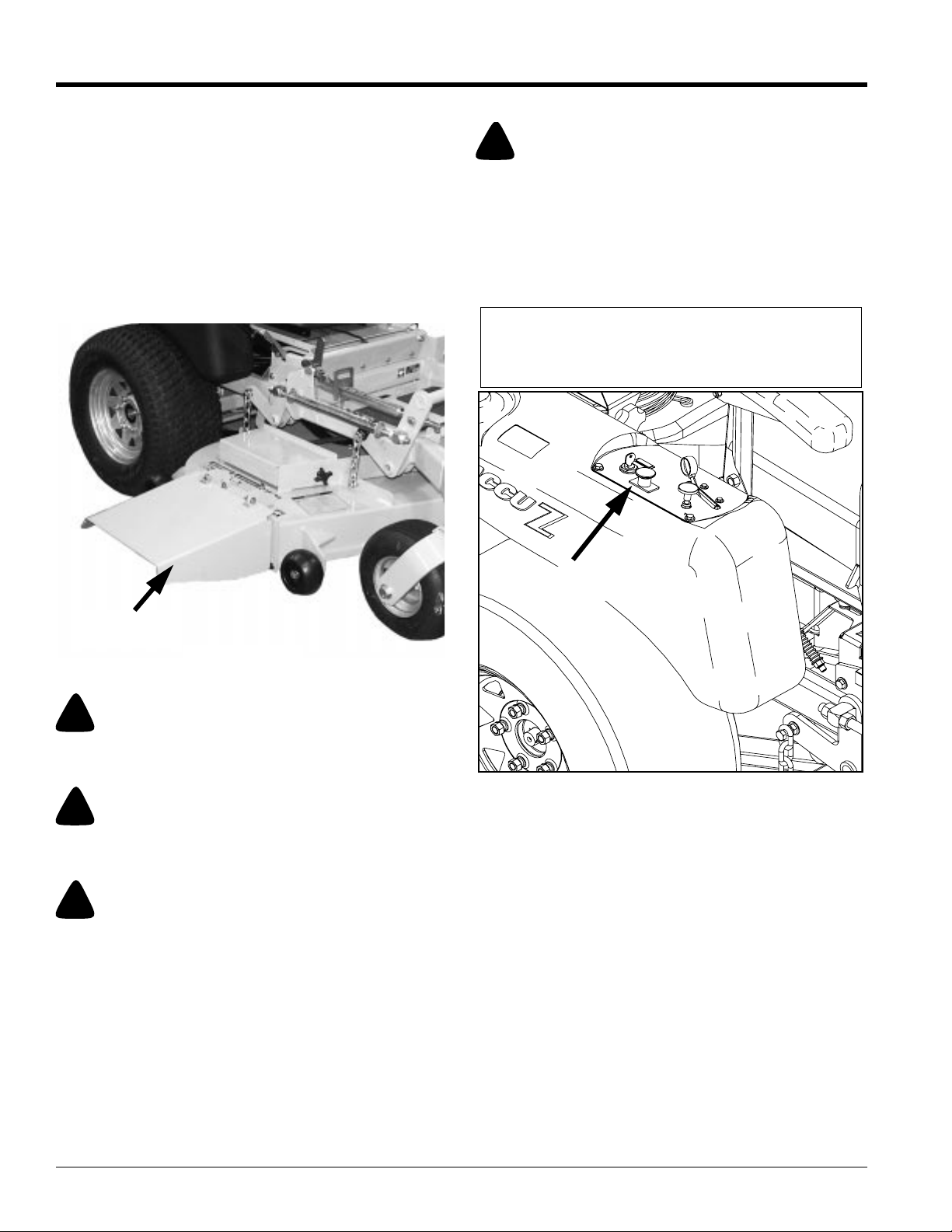
Direct grass discharge to right, away from unmown
area.Selecta mowing patternthat directs grassdischarge
towards the outside, not towards center, of mowing area.
Generally, this means using a pattern utilizing left turns
becauseside discharge is to right. Refer toFigure 2-10. In
any case, avoid throwing grass discharge onto unmowed
area because grass is then mowed twice. Mowing twice
putsan unnecessary loadon theunit andreduces mowing
efficiency.
Mower Deck Operation
!
DANGER!
Neverattempt to makeany adjustments to the mower deck while
the engine is running or with the blade engagement switch
engaged. Mower blades cannot be seen and are located very
close to deck housing. Fingers and toes can be cut off instantly.
With the engine running, engage the blade engagement
switch (Refer to Figure 2-11) and advance engine throttle
to full rpm.
NOTE: Engaging the blade engagement switch at
high engine rpm or when under heavy load (in tall
grassforexample)can cause beltsto slip,resulting in
premature wear or possible damage.
Discharge
Chute
Discharge Chute
Figure 2-10
!
WARNING!
Never direct discharge of material from mower deck towards
bystanders.
!
WARNING!
Never operate the mower deck with dischargechuteremovedor
in raised position.
!
WARNING!
Always check area to be mowed for rocks and other debris
before mowing.
19065
Blade Engagement
Switch
19059
Blade Engagement Switch
Figure 2-11
Z52®, Z60® & Z72® Zero Turning Radius Mowers Accu-Z 356-005M 03/11/03
18
Page 21

Land Pride
Section 2 Operation
Operating Instructions
After thoroughly familiarizing yourself with the Operator’s
Manual and completing the Operator’s Checklist, you are
almost ready to begin mowing.
Approach the mower from the front and make sure the
steering levers are spread fully apart in parking brake
position. Stand just to the outside rear of the left front
anti-scalp wheel and grab the left side steering lever for
support. Taking care not to step on the mower deck, step
up onto the operator’s platform and comfortably seat
yourself. With both steering levers still wide apart, reach
for the throttle and choke control to your right side.
Position the throttle control at half throttle and pull the
choke to the “up/on” position. Insert your ignition key and
rotate the ignition key clockwise until you hear the engine
beginto start. Releasethe ignitionkey andpushthe choke
to “down/off” position. Allow the engine to warm up
momentarily. If your mower has just been running and the
engine is already warm, using the choke is usually not
necessary.
With the engine at half throttle, reach forward and bring
both steering levers equally together in the neutral
position just in front of you. It’s now time to test your
steering skills. Gently push both steering levers equally
forward. The farther forward you push the levers, the
faster you will go. Pull back equally and you will slow
down, coming to a stop when you reach the neutral
position.Now slowlypull thelevers backtoward yourbody
pastneutralposition. Themower willreversedirection and
increase in speed as you pull further back.
If you push one lever forward and pull one lever back the
mower will do a zero turn in the direction of the steering
lever closest to your body. Now take a few moments in a
safe area to practice maneuvering and steering your
mower with the engine still at half throttle. Gradually
increase your throttle speed until you feel totally confident
of your mower steering and handling ability around
obstacles and in tight areas.
It’s now time to cut the grass. You should have already
removedany obstaclesfrom the lawn that youdo notwant
run over. With your mower at half throttle, place your right
foot on the deck lift pedal and release and lower the deck
to your preset cutting height. With your right hand, pull up
on the cutting blade engagement knob and increase the
engine speed to full throttle. You may now begin mowing.
When you are done mowing or just want to take a break,
make sure you do all of the following. Park on level
ground, disengage the cutting blade, throttle back, leave
the steering levers in wide-open parking brake position,
turn the engine off, remove the key, and step carefully off
the left front corner of the operator’s platform.
If your mower is equipped with the Accu-Vac Collection
System and you need to empty the clipping containers, it
is not necessary to shut the engine off. You must,
however, disengage the cutting blade and spread the
steering levers into parking brake position before you
dismountor the unitwill shutoff automaticallywhen you lift
off of the seat. Simply reverse this process when you are
ready to continue mowing.
03/11/03
Z52®, Z60® & Z72® Zero Turning Radius Mowers Accu-Z 356-005M
19
Page 22
Section 3 Adjustments
Section 3
Adjustments
!
WARNING!
Unless specifically required, DO NOT have engine running
when servicing or making adjustments to the mower. Place
control levers in the park brake position and remove ignition
switch key. Repairs or maintenance requiring engine power
should be performed by trained personnel only. To prevent
carbon monoxide poisoning, be sure proper ventilation is
available when engine must be operated in an enclosed area.
Read and observe safety warnings in front of manual.
YourAccuZ wasadjusted beforeit left thefactory andwas
checked during pre-delivery setup. However, after startup and continued use, a certain amount of break-in wear
will cause some adjustments to change.
Remainalert for unusual noises,they could be signalinga
problem. Visually inspect the machine for any abnormal
wearor damage. Agood time todetect potential problems
is while performing scheduled maintenance service.
Correcting the problem as quickly as possible is the best
insurance.
Land Pride
Wheel lug nuts
Wheel motor nut
Blade spindle bolts (top and bottom)
For engine torque values, see engine owner’s manual.
Steering Linkage
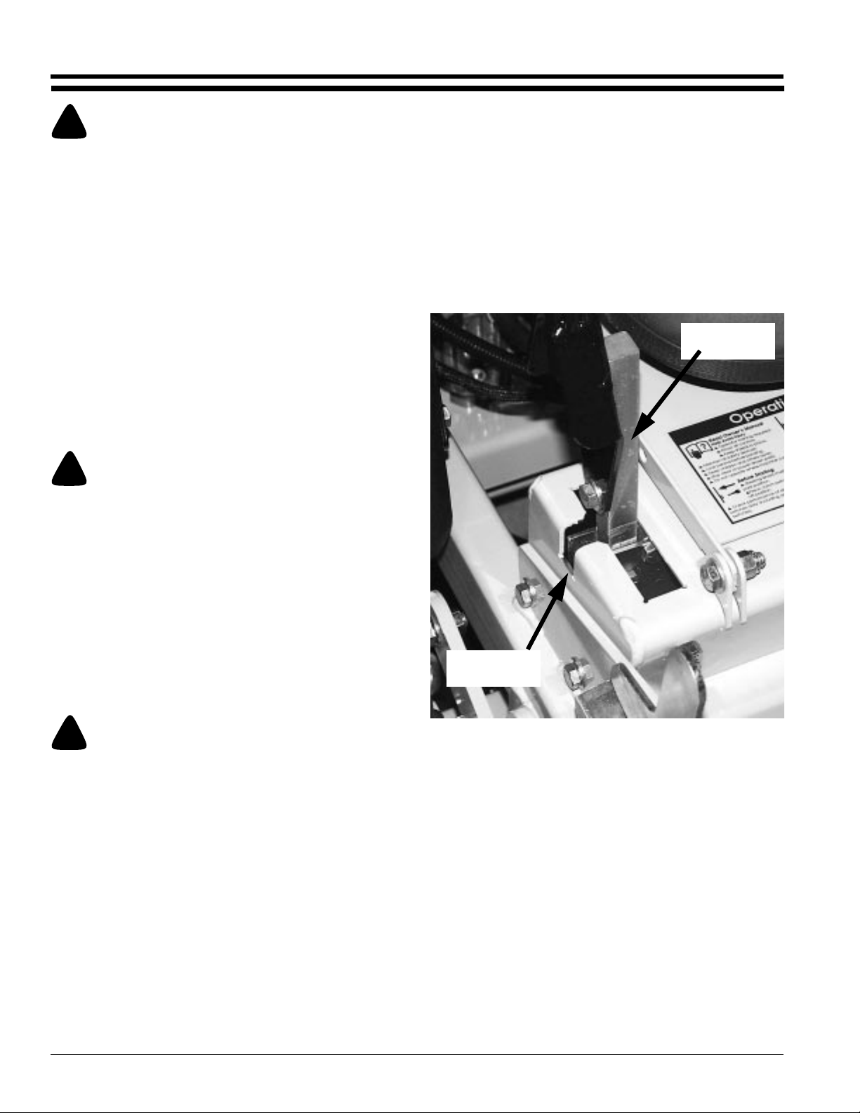
Theneutral adjustment for thecontrol levers in theneutral
position is discussed in this section.
The steering has been factory adjusted to eliminate
creepingwhenthe controllevers are inthe neutralposition
(Refer to Figure 3-1).
Control
Lever
!
WARNING!
Keep your machine clean and remove heavy deposits of trash
and clippings, they can cause engine fires and hydraulic
overheating as well as excessive belt wear.
Clear away heavy build-up of grease, oil and dirt,
especially in the area of reservoir and oil and engine
combustion air; minute dust particles are abrasive to
close-tolerance engine and hydraulic assemblies.
Some repairs require the assistance of a trained service
mechanic and should not be attempted by unskilled
personnel. Consult your Land Pride service center when
assistance is needed.
Torque Values
!
WARNING!
Particular attention must be given to tightening the drive wheel
lug nuts and wheel motor nuts. Failure to correctly torquethese
items may result in the loss of a wheel, which can cause serious
damage or personal injury.
Refer to “Torque Values” on page 32.
It is recommended that the following be checked after the
first2 hours of initial operation, initially andevery 50 hours
following removal for repair or replacement.
Park Brake
Slot
19078
Control Lever In Neutral Position
Figure 3-1
However, should the mower begin to creep, adjustments
can be made as outlined on the following page.
Z52®, Z60® & Z72® Zero Turning Radius Mowers Accu-Z 356-005M 03/11/03
20
Page 23
Land Pride
Section 3 Adjustments
Control Lever Neutral Adjustment
Before considering any adjustment, check the tire air
pressure and make certain hydraulic system oil is at
operating temperature. Unequal tire pressure will cause
the mower to drift to one side. Refer to “Tire Inflation
Chart” on page 44.
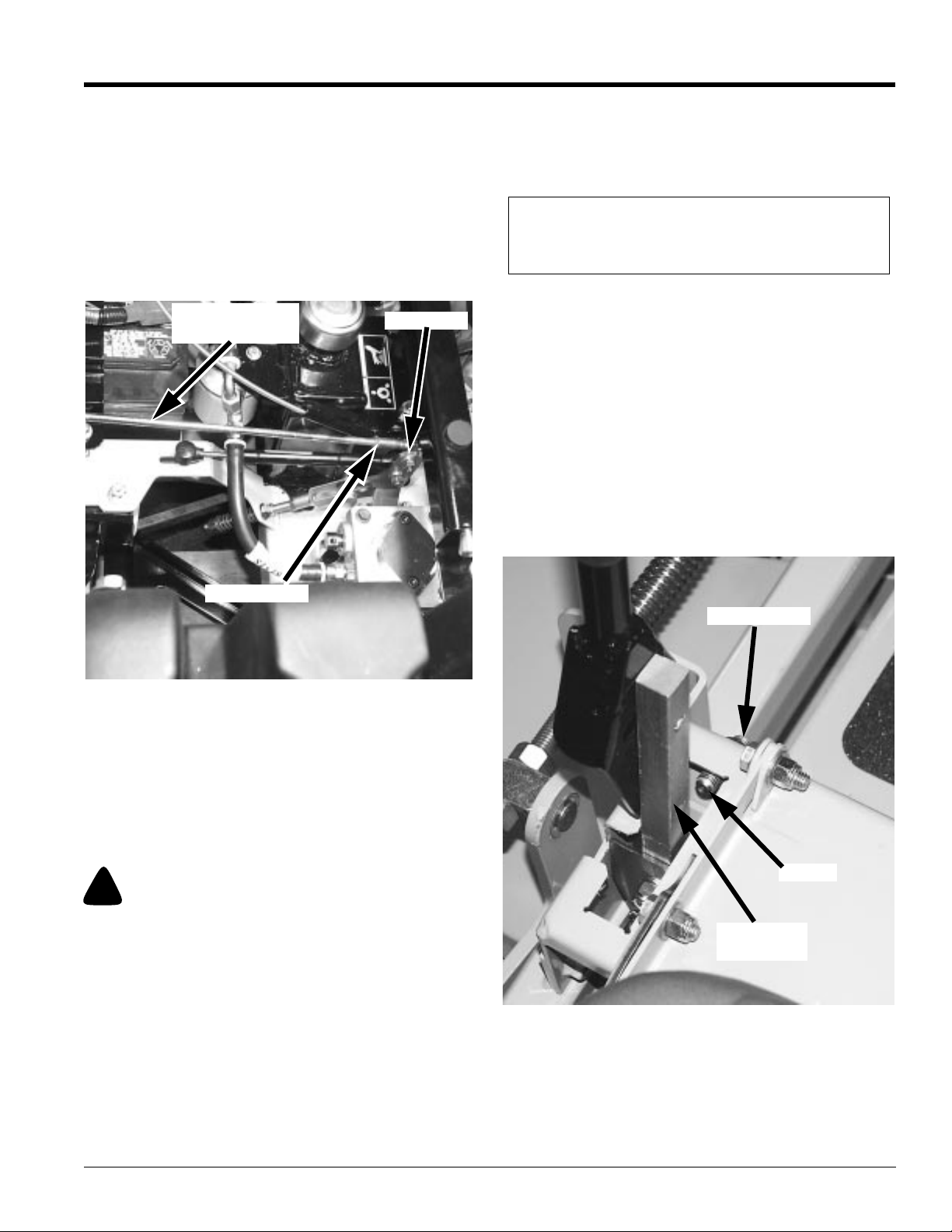
Fine adjustment to the steering is made with the
adjustablepump linkage rodslocated between the control
lever and pump arms. Refer to Figure 3-2.
PumpLinkage
Jam Nut
Rod
4. Ifwheel(s)are rotatingforward,loosenthejam nutson
the pump linkage rods and rotate the rod to lengthen
the steering control linkage until the wheel(s) come to
a stop. Refer to Figure 3-2. Repeat for the opposite
side if necessary.
NOTE: The left linkage controls the right hydraulic
pump and the right linkage controls the left hydraulic
pump.
5. If wheel(s) are rotating in reverse then loosen the jam
nuts on the pump linkage rods and rotate the rod to
shorten the steering control linkage until the wheel(s)
come to a stop. Refer to Figure 3-2. Repeat for the
opposite side if necessary.
6. When both wheels remain in neutral, tighten the jam
nuts to lock the turnbuckle in place.
7. Test again by moving the control levers forward and
backward before returning them to the neutral
position.If thetires are in neutral, theunit isnow ready
for operation.
8. After adjusting for neutral it may be necessary to
re-adjust the reversespring and/or the control lever
stop Refer to Figure 3-3 and Figure 3-4.
Jam Nut
Fine Adjustments to Steering
Figure 3-2
Neutral is properly adjusted when the control levers are in
the neutral position and the drive wheels are not turning.
If the mower creeps in the neutral position the control
linkage may be adjusted as follows:
1. Raiseand blockthe mowerup so thedrivewheels are
off of the floor.
!
WARNING!
Make certain mower is secure when it is raised and placed on
the jack stands. The jack stands should not allow the mower to
move when the engine is running and the drive wheels are
rotating. Use only certified jack stands.
2. Position the control levers in the neutral position.
Disengage the deck clutch.
3. Start the engine and observe which way the wheels
are rotating.
19079
Jam Nut
Stop
Control
Lever
19080
Control Lever Stop
Figure 3-3
03/11/03
Z52®, Z60® & Z72® Zero Turning Radius Mowers Accu-Z 356-005M
21
Page 24
Section 3 Adjustments
Top Nylock
Nut
Reverse
Spring
Lower
Nylock Nut
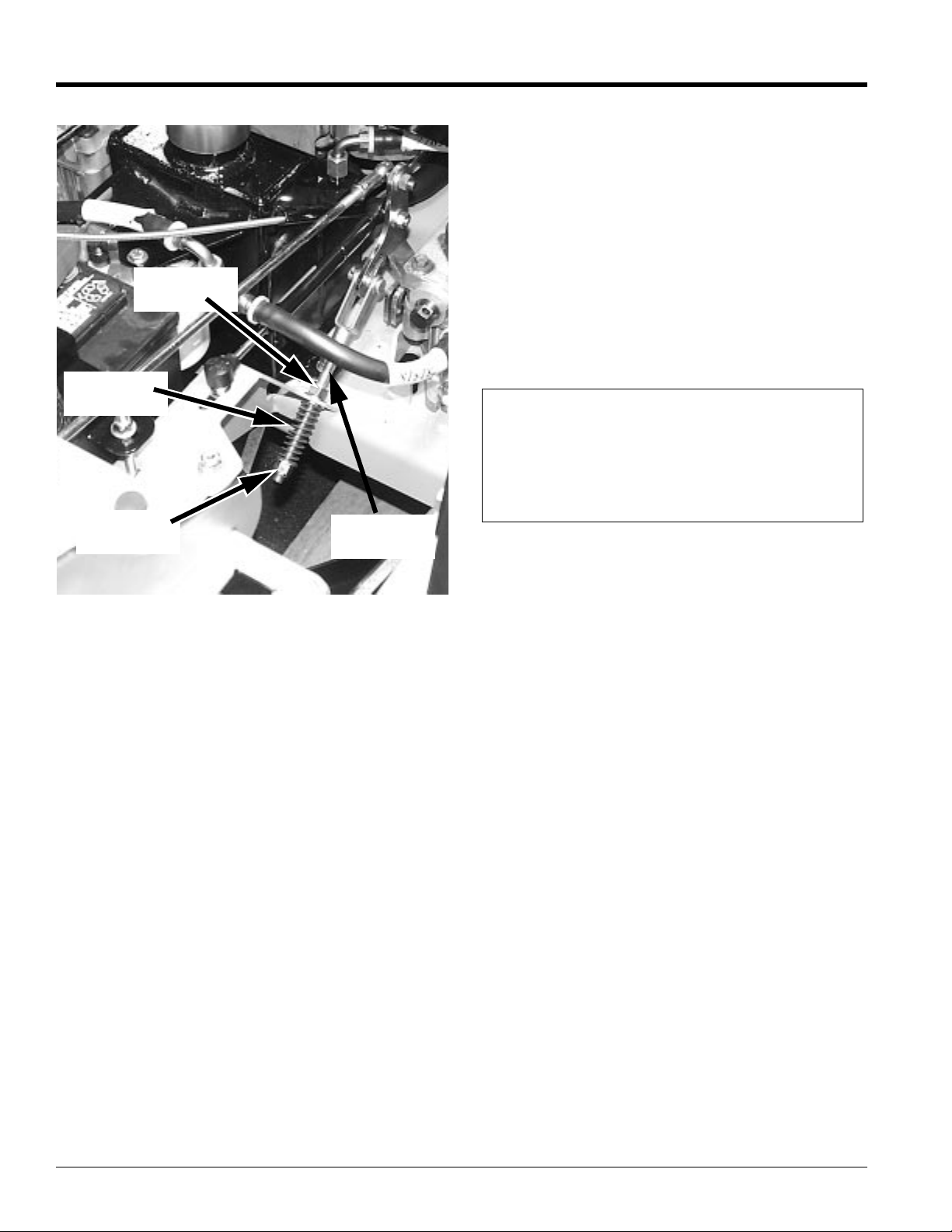
Reverse Spring
Figure 3-4
Spring
Linkage
19081
Control Lever Stops
Thecontrollever stops(Figure3-3) aredesigned to dotwo
things: First, and most important, they must keep the
pumps from bottoming out internally. Second, the stops
may be adjusted to help drive straight when the control
levers are pushed forward against the stops.
To keep the pumps from bottoming out internally use the
following procedure:
1. To make the first adjustment the mower engine must
NOT be running.
2. Check to make sure the control levers are against the
stopsbeforethepumpsare bottomedoutinternally.To
do this, gently and slowly move the control levers
forward and feel if there is some resistance on the
pump lever before the control levers hit the stops.
Check one side at a time. If you sense that the pump
Land Pride
arms are stopping the forward motion of the control
arms, loosen the jam nut on the adjustable stop of the
corresponding side and turn the stop (set screw)
inward to stop the control levers slightly before the
pumpbottoms out.Lock inplace whenthe adjustment
is correct by re-tightening the jam nut.
3. Do this for each side.
To adjust the stops for driving straight when control levers
are against the stops during operation:
Determine which drive tire is rotating too fast when both
control levers are against the stops. Then stop the mower
and loosen the lock nut on the side which is rotating too
fastand turnthe stop (set screw) inwardto stopthe control
lever sooner. Tighten the lock nut on the stop and test
again. Repeat this procedure until unit drives straight.
NOTE: Since this is a hydrostatic drive, variables
such as temperature of oil, efficiency of pumps and
motors,tire pressure etc., may effectthe consistency
of the ability to rely on the stops to drive straight
without the operator making minor steering
adjustments with the control arms.
Reverse Spring Adjustment
Refer to Figure 3-4:
The reverse spring is designed to bring the control levers
to the neutral position after they are released from the
reverse position.
To adjust:
1. Make certain the control leverneutral adjustment is
correct. If not, refer to Steering Linkage section.
2. Whencontrol leverisin thereverseposition the spring
should force the control lever to return to neutral after
the lever is released.
3. Adjustthe top nylocknuton thespring linkageuntil the
control lever returns to the neutral position from the
reverseposition properly. Tightening the nylock nut
will cause the control lever to travel forward less
before stopping. Loosening the nylock nut will allow
the control leverto travelfarther forward.
4. Check the length of the reversespring when the
control leveris in the neutral position. This dimension
shouldbe 1 7/8”. If itis not, adjust the lowernylocknut
until the dimension is achieved.
5. Repeat for other side.
Z52®, Z60® & Z72® Zero Turning Radius Mowers Accu-Z 356-005M 03/11/03
22
Page 25
Land Pride
Section 3 Adjustments
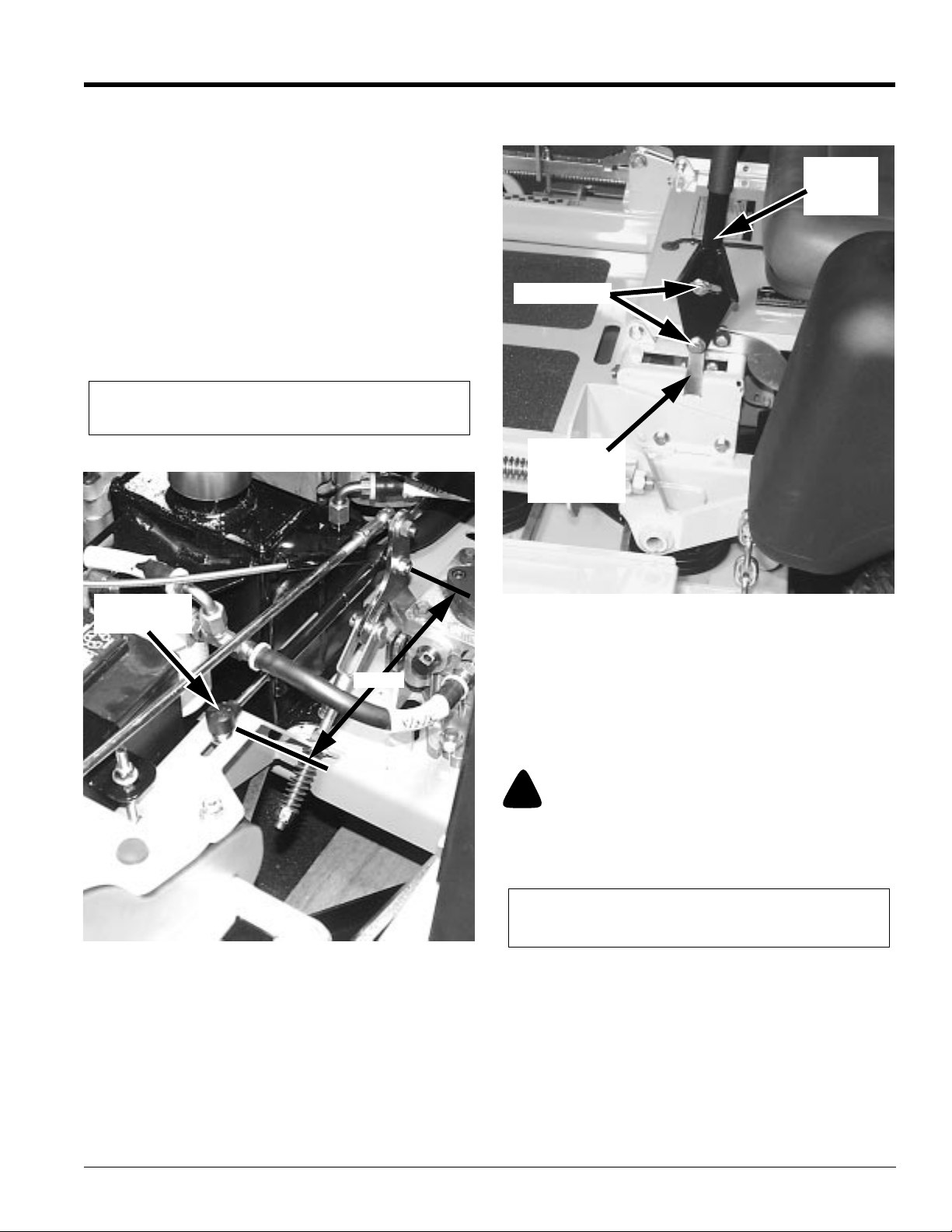
Steering Dampener
Refer to Figure 3-5:
The steering dampeners are incorporated into the unit to
provide some resistance when the control levers are
moving forward or rearward. To set the steering
dampeners in the correct operating position follow these
steps:
1. Place the control lever in the neutral position.
2. Check the center distance from the dampeners front
mounting hole to the rear mounting hole. This
dimension should be 8 9/16”. If it is not, loosen the
front attaching bolt and slide the dampener in the
mounting slot until this dimension is attained.
Re-tighten front attaching bolt.
NOTE:The dampener must not bottom out when the
pump lever is fully stroked in either direction.
The control levers should be adjusted so that they align
with each other when in the neutral position.
Upper
Control
Lever
Cap Screw
Lower
Control
Lever
Steering
Dampener
8.54”
Steering Dampener Adjustment
Figure 3-5
19081
Control Lever Adjustment
The control levers can be adjusted for operator comfort.
By loosening the cap screws that attach the upper control
lever to the lower lever (Fig. 5-6), the upper control lever
can be pivoted to fit the operator s personal preference.
Control Lever Adjustment
Figure 3-6
19082
Park Brake Adjustment
Occasionallycheck the park brakes and adjustment using
the following method:
1. Position the control levers in the neutral position.
Disengage the deck clutch.
!
WARNING!
Make certain mower is secure when it is raised and placed on
the jack stands. The jack stands should not allow the mower to
move when the engine is running and the drive wheels are
rotating. Use only certified jack stands.
NOTE:The front brake link is not adjustable. Refer to
Figure 3-7.
03/11/03
Z52®, Z60® & Z72® Zero Turning Radius Mowers Accu-Z 356-005M
23
Page 26
Section 3 Adjustments
Land Pride
4. Rotate the tire. The tire should rotate. Remember
hydraulic oil resistance will prevent the tire from
rotating freely evenwith the bypass valves open.
There should be no resistance from the brakes at this
point.
5. Move the control lever to where it is touching the
outside edge of the lever’s travel slot.
Refer to Figure 3-9.
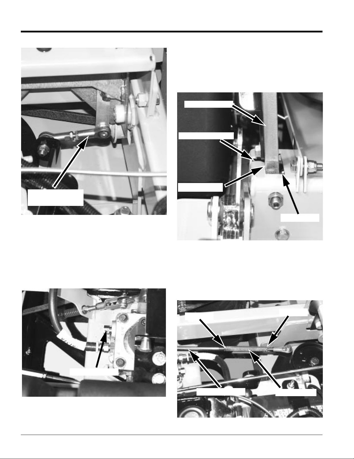
Control Lever
Park Brake Slot
FrontBrake Link
(Right Side)
Front Brake Link
Figure 3-7
2. Raiseand blockthe mowerup so thedrivewheels are
off of the floor.
3. Open the hydraulic pump’s bypass valve (Refer to
Figure 3-8) on the side that is being adjusted, by
turning bypass valvecounter clockwise one-half to
one revolution. The valve stems on each hydraulic
pump are located near the top and are identified as a
hex stud.
19083
Outside Edge
Travel Slot
Control Lever Touching Edge
Figure 3-9
6. Rotatethe tire.Ifthe brakeis adjusted properly thetire
will still rotate but friction will start to become
noticeable here. However, if no brake resistance is
noticed, the brake needs adjusted as follows:
7. Loosen the brake linkage jam nuts. Refer to
Figure 3-10.
Jam Nut
Jam Nut
19084
By-Pass Valve
Brake Linkage
By-Pass Valve
Figure 3-8
Loosen Brake Linkage Jam Nut
Figure 3-10
Z52®, Z60® & Z72® Zero Turning Radius Mowers Accu-Z 356-005M 03/11/03
24
Turnbuckle
19085
Page 27
Land Pride
Section 3 Adjustments
8. Rotate the tire and at the same time rotate the
turnbuckletoshortenthelength ofthebrakelinkage to
increase the brake pressure. When you feel the brake
begin to engage, stop adjusting the turnbuckle. Retighten the jam nuts on the turnbuckle.
9. Place the control lever in the park brake slot. Refer to
Figure3-9. The tire should not rotate whenthe control
leveris in the park brake position.
10. Place the control lever in the neutral position. The tire
should rotate freely.
11. Close the hydraulic pump’s bypass valve.
12. Repeat steps 3 thru 11 for the other side.
13. Remove from the jack stands and lower the unit. It is
now ready to operate.
Hydraulic Pump Belt Adjustment
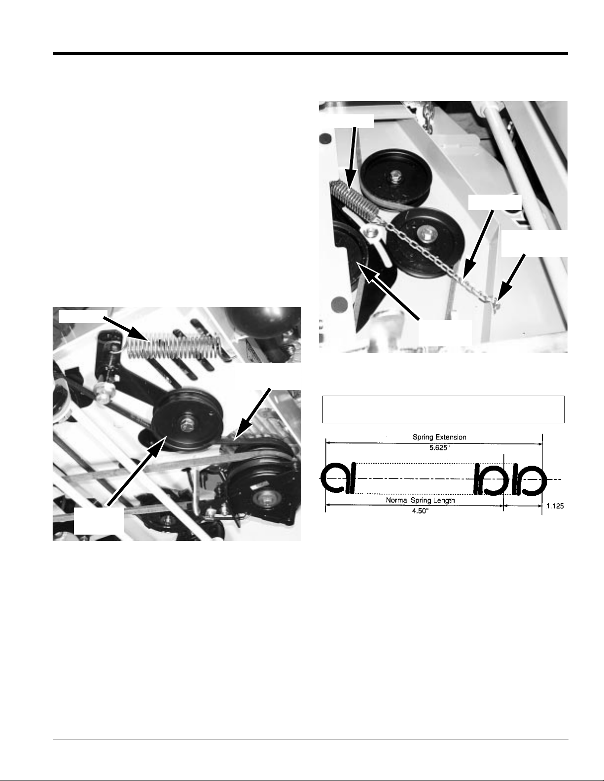
Refer to Figure 3-11.
The pump drive belt tension remains constant by means
of a tension idler and spring. There is no tension
adjustment of this belt.
Spring
link(s)at theanchor bracket (Figure 3-12). Installedspring
length should be 9" + or - 3/8" originally with adjustments
of 5/8" per chain link.
Spring
Chain
Anchor
Bracket
Tension
Idler
PumpDrive
Belt
Tension
Idler
Pump Belt Adjustment
Figure 3-11
19086
Deck Drive Belt Adjustment
Refer to Figure 3-12:
The spindle belt tension remains constant by means of a
tension idler and spring.
The spring tension should be such that the belt does not
slipunder normal operating load conditions,assuming the
beltis not excessivelyworn or damaged.As belt stretches
and wears in, adjustment may become necessary. To
increasebelt tension, movethe springchain one(or more)
Drive Belt Adjustment
Figure 3-12
IMPORTANT: Do not over tension the spring to
compensate for a badly worn belt or pulley.
Spring Tension
Figure 3-13
19087
19091
Engine RPM Setting
The Accu Z is designed so that the engine will run at 3600
rpm static pump load only. At this speed the hydraulic
pumps are running at their maximum rated speed.
Deck Leveling and Height Adjustment
The mower deck has three areas that may need to be
checked and adjusted periodically. Before considering
any mower deck leveling adjustments, check that the tire
air pressure is within the specified range.
03/11/03
Z52®, Z60® & Z72® Zero Turning Radius Mowers Accu-Z 356-005M
25
Page 28
Section 3 Adjustments
Deck Level Adjustments
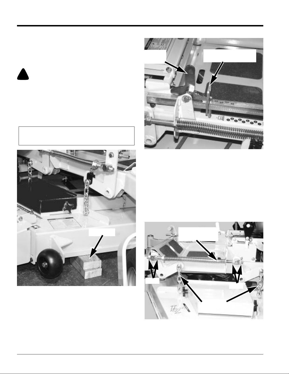
Leveling the deck must be done in the following manner
and order:
1. Checktirepressuresto make certaintheyare properly
inflated before starting to level deck. See “Tire
Inflation Chart” page 44.
!
WARNING!
Stop engine. Make sure deck clutch switch is in the down (OFF)
position. Place control levers in the brake position before
leaving machine.
2. Park the unit on a flat surface.
3. Raise deck and place 3" of blocking under all 4
corners of the deck. This will set the cutting height at
3“. Refer to Figure 3-14.
NOTE: Back of deck will automatically be set 1/4"
higher.
Stop
Handle
Land Pride
Height Adjusting
Stop
Blocking up Deck
Figure 3-14
Blocks
19088
Cutting Height
Figure 3-15
5. Clamp the height adjusting stop against the stop
handle (Figure 3-15). This will assure that the height
will not move during the setting process. Otherwise,
spring pressure from the deck lift springs will tend to
pull the stop away from the handle.
6. Refer to Figure 3-16, Figure 3-17 & Figure 3-18.
Loosen all nuts on the deck lift threaded rods, and the
hardware on the adjuster (on the right front), until all
the deck lift chains are loose, and the deck is sitting
tightly on all four blocks.
19089
Deck Lift
threaded Rod
Nut
Nut
4. Set cutting height at 3" on the height indicator by
placing the height adjusting stop in the 3" hole, and
turning the height stop so that the flat side is against
the stop handle. Refer to Figure Figure 3-15.
Z52®, Z60® & Z72® Zero Turning Radius Mowers Accu-Z 356-005M 03/11/03
26
Deck Level Adjustment
Chain
Figure 3-16
19090
Page 29
Land Pride
Section 3 Adjustments
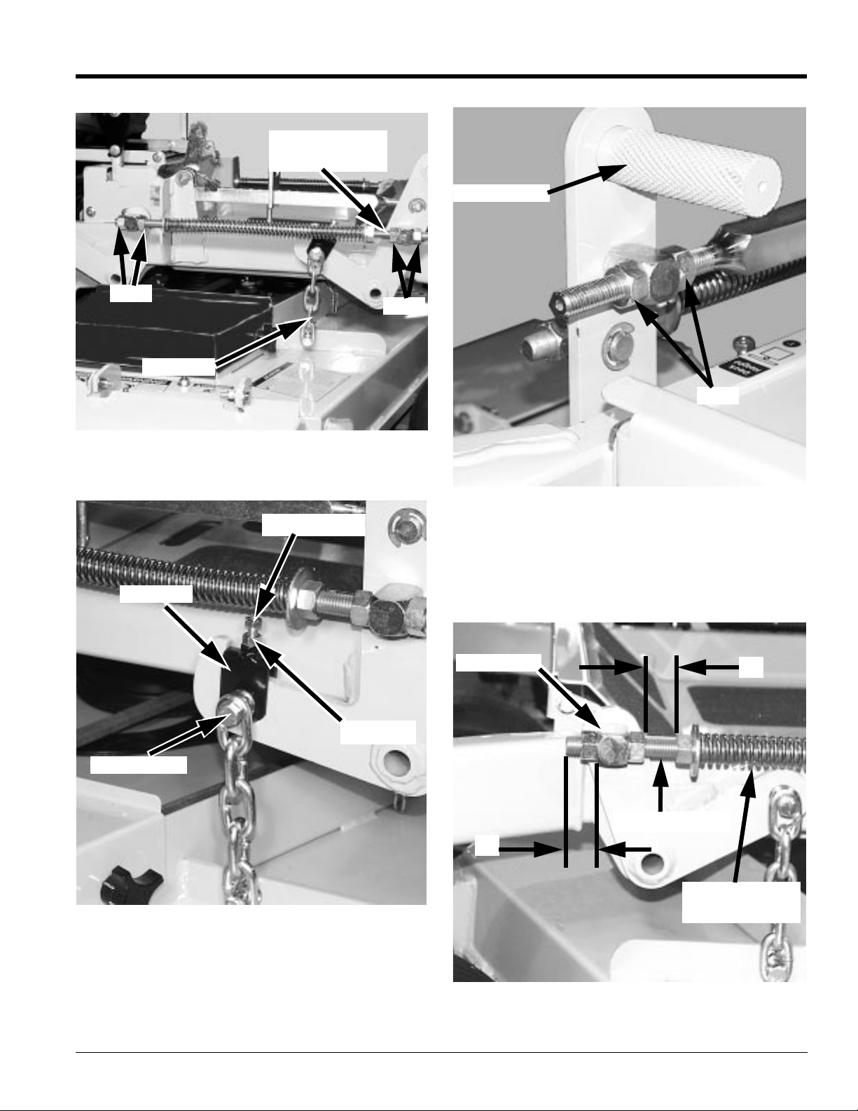
Deck Lift
threaded Rod
Foot Pedal
Nut
Chain
Adjuster
Deck Level Adjustment
Figure 3-17
5/16” Bolt
Nut
19092
Nut
Deck Level Adjustment Foot Pedal
Figure 3-19
8. Start the leveling process on the left front of the
mower.
9. Set the amount of threads protruding on the deck lift
rod from the lift blockat approximately 1".
Refer to Figure 3-20.
Lift Block
19094
1”
Jam Nut
Hardware
Deck Level Adjustment
Figure 3-18
7. Loosen the two nuts on the front of height indicator so
that the foot pedal is free. Refer to Figure 3-19.
03/11/03
19093
Deck Lift Rod
1”
Deck Lift
Assist Springs
Left Rod Protruding Threads
Figure 3-20
Z52®, Z60® & Z72® Zero Turning Radius Mowers Accu-Z 356-005M
19095
27
Page 30
Section 3 Adjustments
Land Pride
10. Jam both nuts against the block.
11. Push or pull on the deck lift foot pedal until the chain
on the left front just becomes tight, making sure that
the deck stays tight against the 3" block.
12. While keeping the chain tight, tighten the nuts against
the deck lift block on the height indicator rod. See
Figure 3-19.
13. Go to the right front of the mower.
14. Loosen the 5/16" jam nut on the adjuster lift chain
(Figure 3-18), and back the adjuster bolt out to allow
the adjuster to move up and down freely.
15. Be sure that adjuster is free to move up and down.
16. Tighten the adjuster bolt until the chain just becomes
tight,making sure that the deckstays tight against the
3" block.
17. Tighten the adjuster bolt jam nut to prevent the
adjuster bolt from moving. See Figure 3-18.
18. Tighten the hardware holding the chain and adjuster
onto the deck lift arm.
19. Go to the right rear of the mower.
20. Make sure that there is still slack in the chain. If not,
loosen the two nuts on the blockholding the threaded
rod until there is slack in the deck lift chain.
See Figure 3-17.
21. Tighten the appropriate nut until the chain just
becomes tight, making sure that the deck stays tight
against the 3" block.
22. Tighten theother nuton the opposite sideof theblock,
and jam them tightly together against the block.
23. Go to the left rear of the mower.
24. Make sure that there is still slack in the chain. If not,
loosen the two nuts on the blockholding the threaded
rod until there is slack in the deck lift chain.
See Figure 3-16.
25. Tighten the appropriate nut until the chain just
becomes tight.
26. Tighten theother nuton the opposite sideof theblock,
and jam them tightly together against the block.
27. Compressthe deckliftassistspringssothat thereis1”
of space between the front nut and on the spring and
therear nuton thedeck liftblock(Figure 3-20).Typical
both sides.
28. When completed, all chains will be tight, and deck
cutting height will be set to the deck height indicator.
Deck Cutting Height Adjustment
Deck height is adjustable from 1” to 5” in 1/4” increments.
The holes in the height adjusting bar are spaced at 1/2”
intervals.By turning the heightadjusting stop around, 1/4”
increments can be attained due to the 1/4” plate that is
part of the stop. Refer to Figure 3-21.
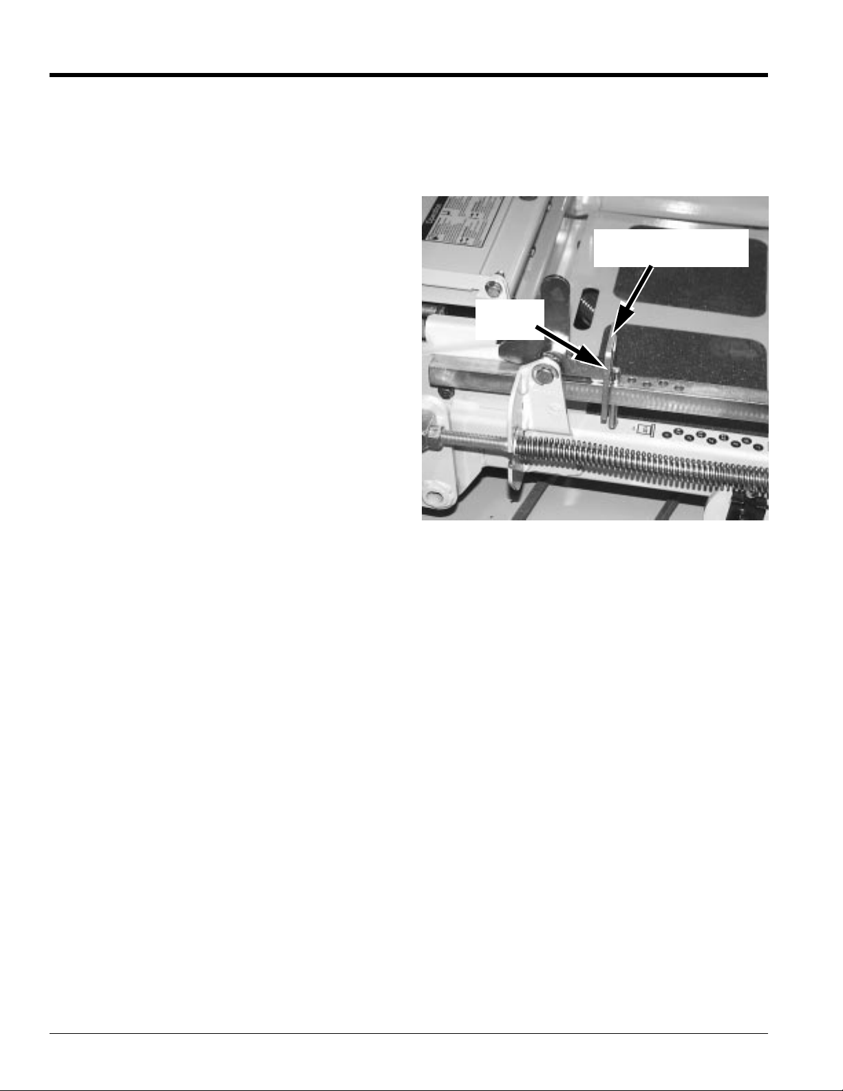
Height Adjusting
Stop
1/4”
Plate
Deck Cutting Height
Figure 3-21
EXAMPLE: When the height adjusting stop is placed in
the1” hole,with the1/4” platefacing tothe front of the unit,
the cutting height is at 1”. When the height adjusting stop
is placed in the 1” hole, with the 1/4” plate on the
operator’s side of the hole, the cutting height is at 1 1/4”.
When the height adjusting stop is placed in one of the
holes,with the1/4” plateon theoperator’s sideof the hole,
the deck height will be set at one of the following: 1 1/4”,
1 3/4”, 2 1/4”, 2 3/4”, 3 1/4”, 3 3/4”, 4 1/4” or 4 3/4”.
When the height adjusting stop is placed in one of the
holes, with the 1/4” plate facing to the front of the unit, the
deckheight willbe set atone ofthe following: 1”,1 1/2”,2”,
2 1/2”, 3”, 3 1/2”, 4”, 4 1/2” or 5”.
The notch located at the rear of the right height adjusting
bar is to used when the deck is placed in the transport
mode.
19089
Z52®, Z60® & Z72® Zero Turning Radius Mowers Accu-Z 356-005M 03/11/03
28
Page 31
Land Pride
Section 3 Adjustments
Anti-Scalp Rollers
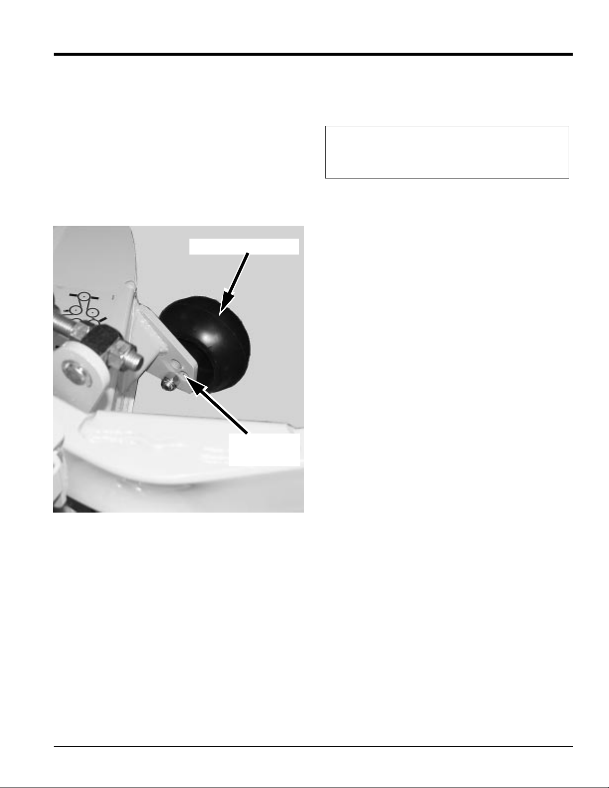
Anti-scalp rollers are standard on the Accu Z. These antiscalp rollers are designed to minimize scalping when
mowing on rough uneven terrain.
After setting the cutting height, adjust the front anti-scalp
rollers so they extend below the deck but do not contact
the ground. They should always be at least 1/4” to 3/4”
below the deck. With the unit sitting on a flat level surface,
the front wheel position can be adjusted up or down as
needed from 3/4” to 1 3/4” below the blade surface. Move
the front wheels up or down, in 1/2” increments, using the
different axle mount holes in the roller mount bracket.
See Figure Figure 3-22.
Anti-Scalp Rollers
Whenadjustingthe rearanti-scalprollers, the rollershould
be in the lower axle mount hole when the front anti-scalp
rollers are in the lower or middle axle mount holes. When
the front rollers are in the upper axle mount hole, the rear
rollers should be in the upper axle mount hole as well.
NOTE: When the anti-scalp rollers are installed, the
minimum cutting height is 1” with the anti-scalp
rollers set at 3/4”.
Anti-Scalp Roller Adjustment
Figure 3-22
Adjusting
Holes
19096
03/11/03
Z52®, Z60® & Z72® Zero Turning Radius Mowers Accu-Z 356-005M
29
Page 32
Section 4 Maintenance and Lubrication
Section 4
Maintenance and Lubrication
Land Pride
4
12
6
7
14
5
13
13
11
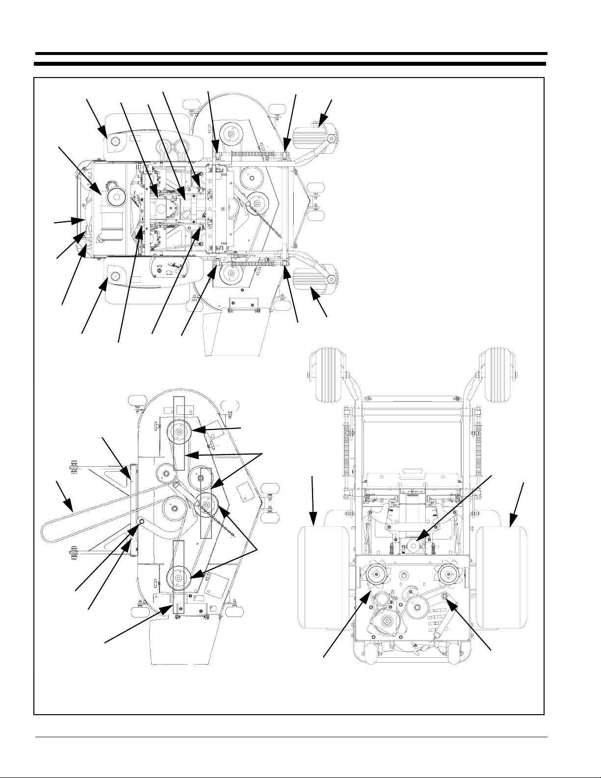
1. Engine Oil Fill & Dipstick
2. Fuel Filter
3. Donaldson Engine Air Cleaner
4. Engine Oil Drain Plug
5. Battery
3
6. Fuel Tanks
7. Hydraulic Oil Reservoir
8. Deck Idler Zerk (1)
9. Deck Pusher Arm Zerks (2)
10. Hydraulic Oil Filter
11. Gauge Wheel Bearing Zerks (2)
12. Engine Oil Filter
13. Deck Height Pivot Zerks (4)
14. Safety Interlock Switch (brake)
15. Drive Tire
16. Pump Idler Zerk (1)
17. Deck Belt
18. Spindle Housing Zerk (3)
19. Pump Belt
20. Blades
1
13
6
2
14
13
11
Top View
17
9
8
9
20
18
18
20
15 10
19
16
15
Deck Top View Bottom View
Maintenance Locations
Figure 4-1
Z52®, Z60® & Z72® Zero Turning Radius Mowers Accu-Z 356-005M 03/11/03
30
Page 33

Land Pride
Section 4 Maintenance and Lubrication
Maintenance Schedule
Service at Intervals Indicated Weekly or 50 Hours Monthly or 100 Hours Annually or 500 Hours
Verify Safety Start Interlock System Daily
Visually Inspect Unit for loose hardware
and/or damaged parts
Visually Inspect Tires Daily
Check Oil Level, Engine (1) Daily or every 4 hours
Clean Air Intake Screen Daily or every 4 hours
Check Fuel Level Daily
Blades - Sharpen & Securely Fastened Daily
Discharge Chute - Securely In Place &
In Lowest Position
Replace Remote Air Cleaner paper
element (6)
Grease Deck Idler X
Grease Deck Pusher Arms X
Grease Pump Idler X
Grease Deck Height Pivots X
Grease Gauge Wheel Bearings X
Change Engine Oil & Filter (1) (4) X
Clean Cylinder And Head Fins (5) X
Check Battery Connections X
Check Tire Pressure With A Gauge X
Check Hydraulic Oil Level X
Clean Engine Exterior (5) X
Clean And Re-gap Spark Plugs (5) X
Check Pump Belt and Deck Belt
for Tension and Condition (7)
Check Fuel And Hydraulic Lines (8) X
Check Fuel Valve And Grommet (8) X
Change Fuel Filter X
Clean Or Replace Hydraulic Fill Cap X
Change Hydraulic Filter And Oil (3) X
Grease Deck Spindle Housings X
Replace Spark Plugs X
NOTES:
1. Initial oil change is after 5 hours of operation. Thereafter,change oil after every 40 hours of operation. Change
more often under dusty or dirty conditions and during hot weather periods.
2. Torque initially and after first 2 hours of operation.
3. Perform initial hydraulic filter change after 50 hours (one week) of operation.
4. Change engine oil filter per the engine manufacturer’s recommendations. Refer to Engine Owner’s Manual.
5. Refer to Engine Owner’s Manual.
6. Service more often under dusty or dirty conditions. Use caution when servicing to prevent dust contamination in
the engine. Do not clean filter element. Replace with a new one.
7. Inspect every 100 hours and replace if worn or cracking is noticed. Otherwise, replace every 1000 hours or 2
years whichever comes first.
8. Check fuel line hoses, fuel valveand grommet for any cracks or leaks.
Daily
Daily
As needed
X
03/11/03
Z52®, Z60® & Z72® Zero Turning Radius Mowers Accu-Z 356-005M
31
Page 34
Section 4 Maintenance and Lubrication
NOTE: After completing maintenance cycle
(500 hours), repeat cycle.
Land Pride
!
WARNING!
Keepyour machine clean and remove any deposits of trash and
clippings, which can cause engine fires and hydraulic
overheating as well as excessive belt wear.
Maintenance
!
WARNING!
Unless specifically required, DO NOT have engine running
when servicing or making adjustments to mower. Place control
levers in the neutral position, disengage deck clutch, and
remove ignition switch key. Repairs or maintenance requiring
engine power should be performed by trained personnel only.
To prevent carbon monoxide poisoning, be sure proper
ventilation is available when engine must be operated in an
enclosed area. Read and observe safety warnings in front of
manual.
!
Before working on or under the deck, make certain engine
cannot be accidentally started. Shut engine off and remove
ignitionswitchkeyfor maximum safety.Repairs or maintenance
requiring engine power should be performed by trained
personnel only.
Exercise caution when working under the deck as the mower
blades are extremely sharp. Wearing gloves is advisable when
working around or with the blades.
DANGER!
!
DANGER!
Clear away heavy build-up of grease, oil and dirt,
especially in the engine and hydraulic reservoir area;
minute dust particles are abrasive to close-tolerance
engine and hydraulic assemblies.
Daily inspect mower for grass clippings and wire and
string tangles. The underside of the mower deck will
collect a build-up of grass clippings and dirt, especially
when grass is wet or has high moisture content. This
build-up will harden, restricting blade and air movement
and will probably show a poorer quality of cutting.
Therefore it should be removed routinely.
To do this it will be necessary to raise and block the deck
in the full up position and scrape the build-up from
underneath.
Some repairs require the assistance of a trained service
mechanic and should not be attempted by unskilled
personnel. Consult your Land Pride dealer when
assistance is needed.
Torque Values
!
WARNING!
Particular attention must be given to tightening the drive wheel
lug nuts, wheel motor nuts, and blade spindle nuts. Failure to
correctly torque these items may result in the loss of a wheel or
blade, which can cause serious damage or personal injury.
!
WARNING!
Exceptwhen changing orcheckingbelt, always keepbelt covers
on mower for safety as well as cleanliness.
!
WARNING!
When possible, clean under mower using a stick or similar
instrumentmaking sure that no partof the body,especially arms
and hands are under mower.
Regular maintenance is the best prevention for costly
downtime or expensive, premature repair. The following
pages contain suggested maintenance information and
schedules which the operator should follow on a routine
basis.
Remainalert for unusual noises,they could be signalinga
problem. Visually inspect the machine for any abnormal
wearor damage. Agood time todetect potential problems
is while performing scheduled maintenance service.
Correcting the problem as quickly as possible is the best
insurance.
Torque Values
FT - lbs. Nm
Wheel lug nuts 65 - 75 88.14 - 101.7
Wheel motor nut 350 - 375 474.6 - 508.5
Blade spindle bolts (top
and bottom)
It is recommended that these be checked after the first 2
hours of initial operation and every 50 hours following
removal for repair or replacement.
For all other torques refer to “Torque Values Chart”
page 44.
For engine torque values, see engine owner’s manual.
65 - 75 88.14 - 101.7
Tires
It is important for level mowing that the tires have the
same amount of air pressure.
Refer to “Tire Inflation Chart” page 44.
Solidfill tires are not recommended for theAccu Z mower.
On any machine, with solid filled tires, the warranty claim
will be denied.
Z52®, Z60® & Z72® Zero Turning Radius Mowers Accu-Z 356-005M 03/11/03
32
Page 35
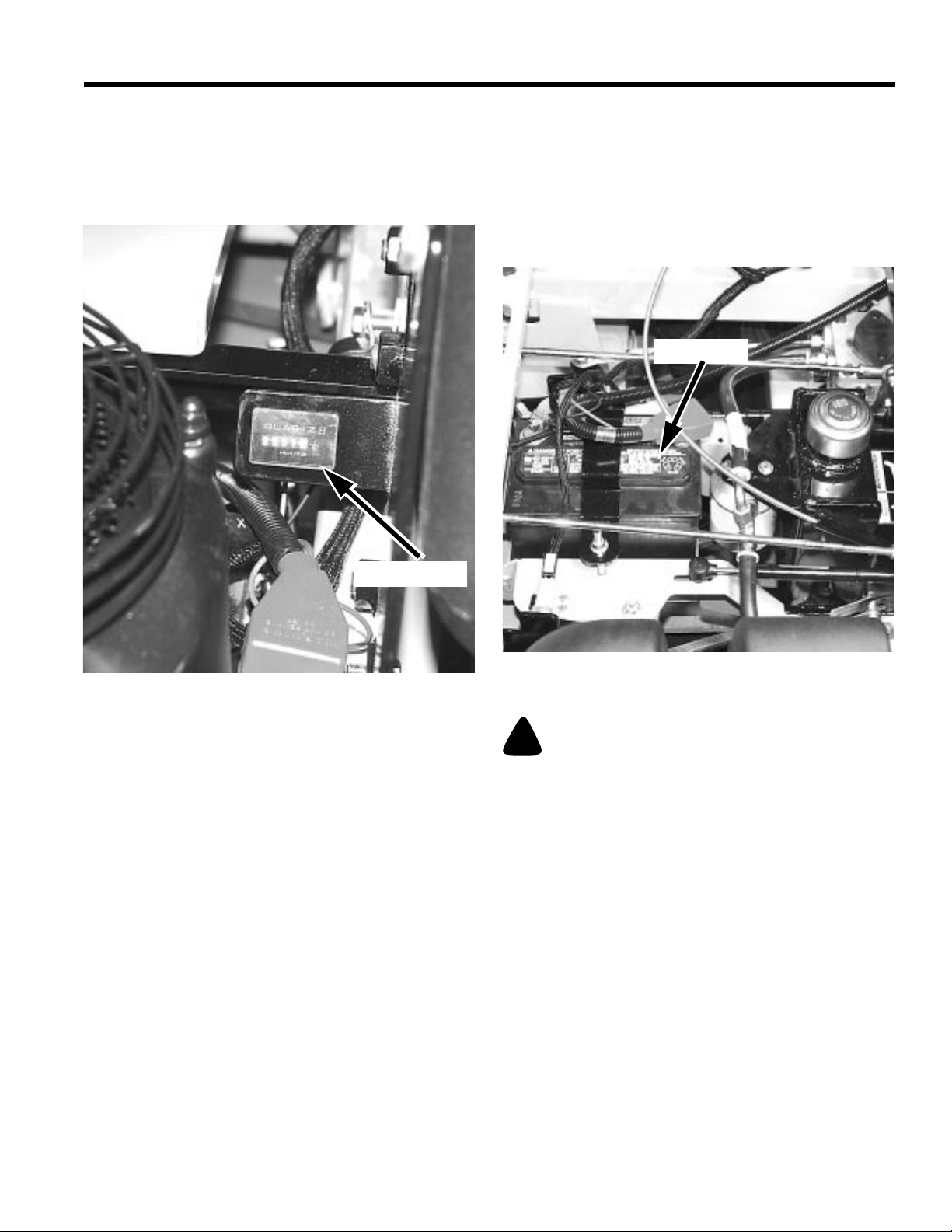
Land Pride
Section 4 Maintenance and Lubrication
Hour Meter
To recognize when your machine needs servicing, check
the hour meter and the maintenance schedule. The hour
meter shows the number of hours the engine has run and
the maintenance schedule lists the service intervals. See
Figure 4-2.
Electrical System
The electrical system is a 12 volt, negative ground.
Recommended battery size is a garden mower BCI group
U1R with 225 or better cranking AMP rating. A
maintenance-free battery is recommended. Otherwise,
followbatterymanufacturer’smaintenance, safety,storing
and charging specifications.
The battery is located under the seat. See Figure 4-3.
Battery
Hour Meter
Hour Meter
Figure 4-2
19062
Lubrication
1. Grease the front gauge wheel bearings per the
Maintenance Schedule. Use SAE multi-purpose
grease.
2. Grease the four deck lift pivots, located to the side of
theoperator’sfootrestperthe MaintenanceSchedule.
Use SAE multi-purpose grease.
3. Grease the deck idler per the Maintenance Schedule.
Use SAE multi-purpose grease.
4. Grease the pump idler per the Maintenance
Schedule. Use SAE multi-purpose grease.
5. Grease the two deck pusher arm pivots per the
Maintenance Schedule. Use SAE multi-purpose
grease.
6. Grease the blade spindle assemblies per the
Maintenance Schedule. Each spindle shaft is
equipped with a grease zerk located under the deck.
Use no more than one or two ounces of SAE
multi-purpose grease, (1 to 2 pumps on an average
grease gun). Do not force lubricant into grease zerks.
Bearings are sealed and do not require much
lubricant.
Battery
Figure 4-3
!
WARNING!
Avoid skin contact with battery acid. Always wear eye
protection when checking the battery, acid can cause serious
injury to skin and eyes. If contact occurs, flush area with clean
water and call physician immediately. Acid will also damage
clothing. Do not allow open flame near the battery when
charging. Hydrogen gas forms inside the battery. This gas is
both toxic and flammable and may cause an explosion if
exposed to flame. Always remove the negative ground first and
replaceit last. Do not overfill battery. Electrolytemay overflow
and damage paint, wiring or structure. When cleaning the
battery, use soap and water. Be careful not to get soap and
water into the battery. Use soda mixed in water to clean
corrosion off the terminals.
Common circuit failures are usually caused by shorting,
corroded or dirty terminals, loose connections, defective
wire insulation or broken wires. Switches, solenoids and
ignition components may also fail, causing a shorted or
open circuit.
Before attempting any failure diagnosis of the electrical
system, use a test light or voltmeter to check the battery
voltage. If the battery voltage is satisfactory, check the
19069
03/11/03
Z52®, Z60® & Z72® Zero Turning Radius Mowers Accu-Z 356-005M
33
Page 36
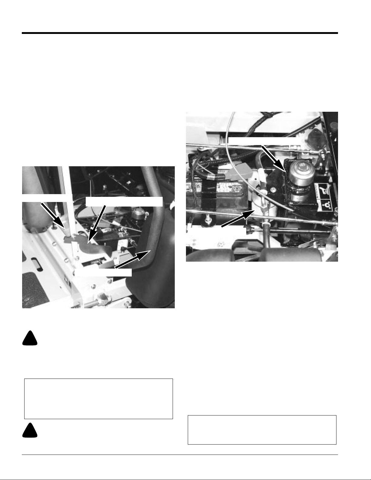
Section 4 Maintenance and Lubrication
Land Pride
cleanliness and tightness of the terminals and ground
connections. A general understanding of electrical
servicingand use of basictest equipment is necessary for
troubleshooting and repair.
Major overhaul or repair of the starting motor or alternator
should be performed by trained technicians only.
Access to Engine and Hydraulic
Pumps
The hydraulic pumps are accessed by lifting the seat
platform. The seat platform is hinged at the front. To raise
it, release seat latch and tilt seat platform up and forward.
The seat platform catch (See Figure 4-4) will prevent the
seat from going all the way over. However,if more access
is desired under the seat platform, the seat platform catch
can be raised allowing the seat to pivot more. Make
certainto place the control arms in the park brakeposition
and lift the seat arms before raising the seat.
Seat Platform
Seat Platform Catch
the skin. If exposed to hydraulic fluid, see a doctor at once.
Before applying pressure to hydraulic system, make sure all
connections are tight and all hoses and lines are in good
condition. To find a leak under pressure, use a piece of
cardboard or wood, never use your hands. Relieve all pressure
in the system before disconnecting or working on hydraulic
lines. To relieve pressure, place control levers in park.
The 1.0 U.S. gallon (3.79 liter) hydraulic reservoir is
located in front of the engine and under the operator’s
platform. See Figure 4-5.
Hydraulic Reservoir
Control Lever
Access to Engine and Hydraulic Pumps
Figure 4-4
!
WARNING!
Always wear adequate eye protection when servicing the
hydraulic system and battery.
Hydraulic System
IMPORTANT:Never use hydraulic or automatic
transmission fluid in thissystem; use only motor oil as
specified.Remember,dirt is the primary enemy ofany
hydraulic system.
19070
Hydraulic Filter
Hydraulic Reservoir and Filter
Figure 4-5
Check oil level in hydraulic system after every 50 hours of
operation or weekly, whichever occurs first. Check more
often if system appears to be leaking or otherwise
malfunctioning.
Fluid level should be 1” from top of reservoir. Use only
SAE 10W40 SG, SF/CC, CD service motor oil.
Change hydraulic system filter element (Land Pride P/N
831-030C) (Fig. 4-5) after first 50 hours of mower
operation, then replace filter and oil in reservoir every 500
hoursthereafter. When changing hydraulicoil use 1/2 unit
(approximately 3.5 oz.) of Lubrizol additive (Land Pride
P/N 821-041C). This additive, available from your Land
Pride dealer, will increase the performance life of the
hydraulic system components.
Thesystem filter is located directly in front of thehydraulic
reservoir. A standard oil filter wrench is used to change
filter, threads are right handed. Use an Accu Z approved
filter element only (Land Pride P/N 831-030C).
19069
IMPORTANT:Pre-fill the filter element with clean oil,
!
WARNING!
Hydraulic oil escaping under pressure can penetrate skin.
Hydraulic oil may cause infection in a minor cut or opening in
Z52®, Z60® & Z72® Zero Turning Radius Mowers Accu-Z 356-005M 03/11/03
34
beforeinstalling,to preventdrawingairinto thesystem
pump.
Page 37
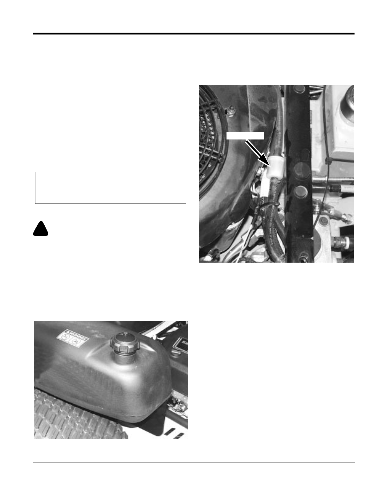
Land Pride
Section 4 Maintenance and Lubrication
1. Fill the filter element with clean system oil. Smear a
light coating of oil on upper surface of rubber seal.
2. Install the filter element on base. Tighten the oil filter
byhanduntil the filterseal makescontactwith the filter
head, then tighten an additional 3/4” turn with an oil
filter wrench. DO NOT OVERTIGHTEN.
3. Start mower engine and let run at approximately 2/3
throttlefor a fewminutes towork anytrapped air out of
thesystem beforeengaging the steering control lever.
4. Stop the engine and check the filter and connections
for leaks.
5. Check the hydraulic reservoir for specified oil level.
Add clean oil as necessary.
Clean or replace hydraulic reservoir cap annually. Cap
may be cleaned by dipping in or flushing with cleaning
solvent. Follow manufacturer’s instructions and warnings
for application of solvent type selected.
NOTE: The hydraulic pumps are equipped with
bypass valves. For more information refer to
Operation section, “Moving Mower with Stalled
Fuel System
Use regular unleaded gasoline with an octane rating of 87
or higher.
Referto Figure 4-7.The fuelfilter isinstalled inthe fuel line
betweenfuel tanks and engine fuel pump on the frontside
of the engine. Replace filter annually or after every 500
hours of operation, whichever occurs first.
Fuel Filter
!
WARNING!
Observe usual fuel handling precautions; do not smoke while
refueling,do not fill tank with engine running or while engine is
hot, allow engine to cool before storing machine inside a
building, keep fuel away from open flame or spark and store
machine away from open flame or spark if there is fuel in the
tank. Read and observe safety precautions at front of this
manual.
The fuel tanks are located in the mower’s fenders. (See
Figure 4-6) Total capacity for the fuel tanks is 12 U.S.
gallons.
Fuel Filter
Figure 4-7
When replacing the fuel filter, check the fuel line hoses for
any cracks or leaks. Replace as needed.
19071
Engine Oil and Filter
Refer to Figure 4-8:
Check engine oil daily and after every 4 hours of
operation. Crankcase dipstick and oil filler tube are
located at the rear of the machine. Mower must be sitting
level when checking oil. Refer to engine manual and
maintenance schedule for oil recommendation and
capacities.
Change the engine oil and filter after the first 5 hours of
operation, per the engine manufacturer’s
recommendationsafter that. If moweris being operated in
extremely dirty conditions, then it is recommended oil be
changed more frequently.
The oil drain and oil filter are located at the rear of the
engine.
03/11/03
Fuel Tank
Figure 4-6
19071
Z52®, Z60® & Z72® Zero Turning Radius Mowers Accu-Z 356-005M
35
Page 38
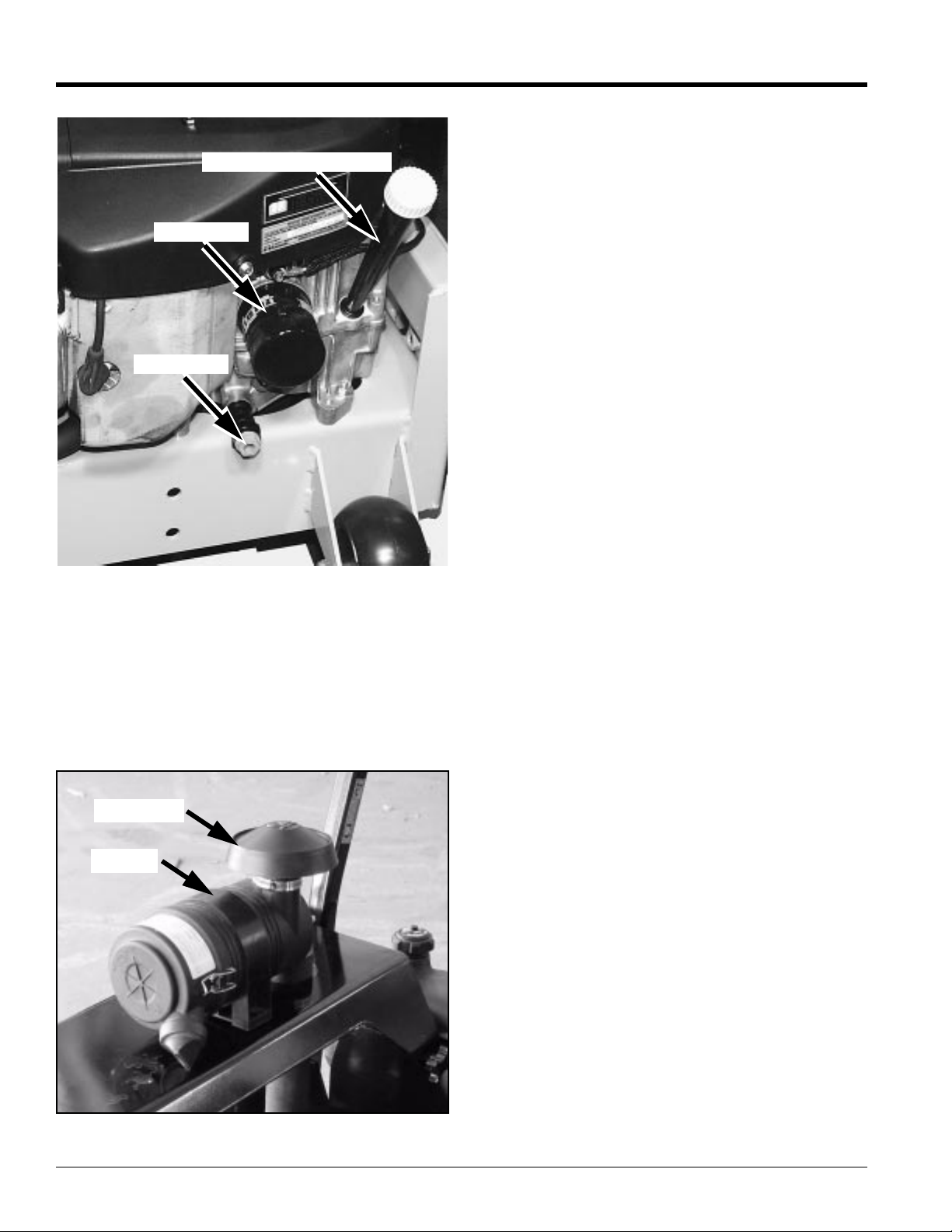
Section 4 Maintenance and Lubrication
Engine Oil Filler Tube
Oil Filter
Drain Plug
19072
Kawasaki Engine Shown
Figure 4-8
Engine Air Filter
Refer to Figure 4-9
Perform engine air filter maintenance per Maintenance
Schedule on page 31.
A specially designed dry filter is standard equipment on
the mower and supplies clean combustion air to the
engine.
Pre-cleaner
Canister
Figure 4-9
Land Pride
Many engine failures can be attributed to improper air
cleaner servicing. Ingested dust and dirt will cause
cylinder, piston and bearing damage in a few hours.
Dusted engines will result from:
1. Over servicing the air filter element.
2. Improper installation of an air filter element.
3. Damaged filter, seals or canister.
4. Incorrect air filter element size and/or use of poorly
designed aftermarket air filter elements.
Air cleaner servicing is an inexpensive maintenance
check that can prevent costly non-warrantable premature
engine damage.
Over Servicing
Over servicing occurs when an air filter element is
removed for cleaning or replacement before it is
necessary.Each time the filteris removed a small amount
of dirt and dust could fall in the intake system. This
accumulated dirt can cause a dusted engine. It only takes
a few grams of ingested dirt over the normal service life of
an engine to cause a dusted engine.
Do not clean element, replace with a new element
only. Cleaning used air filter elements, through improper
cleaningprocedures, canget duston theinside ofthe filter
causing dirt ingestion and engine failure.
It is important to note that whenever an air filter element is
cleaned by any method, the person or company
performing the cleaning assumes responsibility for the
integrity of the filter from then on. The Donaldson
warranty for air filters expires upon cleaning or
servicing in any manner because the condition of the
filter after servicing is completely out of their control.
Therefore,on a dust ingested engine failure, therewill
be no warranty consideration if the air filter element
has been cleaned or serviced in any manner.
A partially dirty air filter element works better than a new
element. Therefore, a dirty filter element is not bad for the
engine unless it is excessively restricting the air flow and
engineperformanceis affected.The reasonissimple. The
media in the filter must be porous to allow air to pass
through it. When dirty air passes through the filter, the dirt
plugs some of the holes in the media and actually acts as
part of the filter media. When the next round of dirt enters,
the first dirt helps filter out even smaller particles making
the filter more efficient at stopping dirt from entering the
engine. This is referred to as barrier filtration.
Of course, at some point the filter media becomes too
clogged to allow air to pass.
The mowing conditions will determine the frequency of air
filter element changing.
Improper Installation
Dust must not leak past the seals on each end of the air
filterelement. Thefilter mustbe alignedwithin thecanister
andproperly seatedfor an effectiveseal sothat nodirt can
enter the engine.
Z52®, Z60® & Z72® Zero Turning Radius Mowers Accu-Z 356-005M 03/11/03
36
Page 39
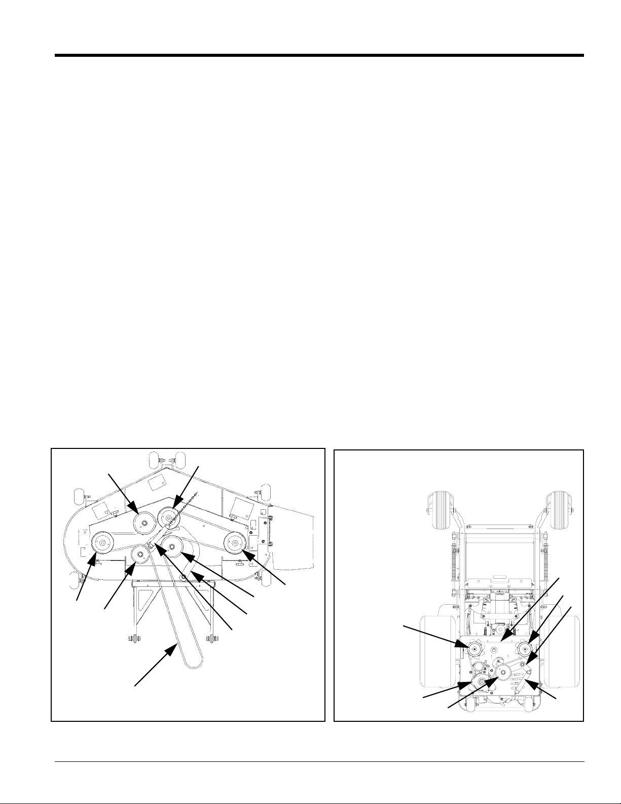
Land Pride
Section 4 Maintenance and Lubrication
Damaged Filter, Seals or Canister
Never bang or bump the filter element against the tire or
any solid object, as dust and dirt particles will be forced
through the media causing continual passing of dirt into
the engine. Visually inspect the outside of the air cleaner
canister periodically for external damage and replace if
necessary.
Incorrect Air Filter Element
Use only the correct Donaldson air filter element, Land
Pride part number 839-312C, which is designed to fit the
canister properly. Land Pride air filter elements have the
correct media composition, filter area, micron size and
dimensions. Always use genuine Land Pride filters. Many
aftermarket filters have been found to be incompatible
with Land Pride’s canisters and engines.
The air filter must remain intact to block passage of dirt
and foreign particles from entering the engine. Being
inclinedto disbelieve the need formore expensive air filter
elements used on gasoline engines may cause some
individuals to opt for a less expensive part.
The filter element must be sufficient size and construction
to withstand stresses, caused by rapid cycling of the air
volume demanded by the engine, without cracking or
tearing under fatigue and pressure (especially diesel
engines). Therefore, Land Pride and the engine
manufacturers have carefully selected a reliable filter
designed to fit the needs of the engines. The filter
specified is a Donaldson filter, Land Pride part number
839-312C.
Owners should be reminded that failure to use original
equipment replacement parts is an alteration and will not
beconsidered for warrantyin theevent ofengine damage.
Engine Air Filter Service Procedure
1. Release clamps and remove element. Clean the
canister with a damp cloth.
2. Beforeinstallinga newelement, inspect it byplacing a
bright light inside and rotate the element slowly,
looking forany holes or tears in the paper. Also check
gaskets for cuts or tears. Do not attempt to use a
damaged element which will allow abrasive particles
to enter the engine.
3. Reinstall the dust cup. Make sure it seals all the way
around the air cleaner body, then tighten the clamps.
4. Checkall fittings and clamps periodically for tightness
and inspect hoses for holes or cracks.
5. Periodically check the intake hose for signs of
ingested dust. Locate and repair the source of
ingested dirt.
6. Neveroperate a machine without an air filter installed.
General Engine Maintenance
Detailed instructions and recommendations for break-in
and regular maintenance are specified in the Engine
Operator’s manual. Please refer to this manual for engine
servicing, lubricating oil levels with quality and viscosity
recommendations, bolt torques, etc. The engine warranty
is backed by the engine manufacturer. Special attention
should be paid to applicable data which will not be
duplicated here.
19067
5
2
3
1
Deck Belt Drive Layout
Figure 4-10
2
5
6
4
1. Spindle drive belt
2. Deck blade spindle pulley
3. Spindle belt tension idler
4. Spindle belt tension idler
spring (9.0" at operation)
5. Deck belt idler
6. Idler arm
2
1. Pump belt
2. Engine pulley
3. Pump idler pulley
4. Pump idler arm
5. Pump pulley
6. Electric deck clutch
7. Pump idler spring
5
19068
Mower Viewed from Bottom Deck
2,6
3
Figure 4-11
1
5
4
7
03/11/03
Z52®, Z60® & Z72® Zero Turning Radius Mowers Accu-Z 356-005M
37
Page 40
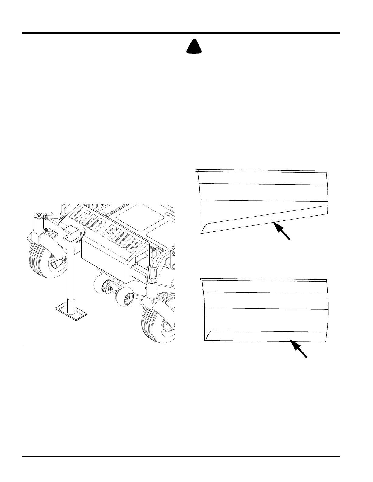
Section 4 Maintenance and Lubrication
Belt Replacement
Refer to Figure 4-10 and Figure 4-11:
Replace belts which show signs of severe cuts, tears,
excessive weather checking and cracking or burns
caused by slipping. Slight raveling of belt covering does
not indicate failure, trim ravelings with a sharp knife.
Inspect the belt pulley grooves and flanges for wear. A
new belt, or one in good condition, should never run
againstthe bottomof thegroove. Replacethe pulleywhen
this is the case, otherwise belt will lose power and slip
excessively.
Never pry a belt to get it on a pulley as this will cut or
damage the fibers of the belt covering.
Keep oil and grease away from belts, and never use belt
dressings.Any of thesewill destroythe beltcomposition in
a very short time.
Mower Blade Maintenance
Lift Jack Option
Foreasier blade maintenance alift jack can bepurchased
fromyour LandPride Dealerand easilyassembled toyour
mower. Refer to Figure 4-12.
Land Pride
!
DANGER!
Never work with blades while engine is running or deck clutch
is engaged. Always place deck clutch in the disengaged
position, place control levers in park position and turn engine
off. Block up mower when you must work under it. Do not use
jack as blocks. Jack is for lifting only. Separate blocks must be
used prior to servicing under mower. Wear gloves when
handling blades. Always check for blade damage if mower
strikes rock, branch or other foreign object during mowing!
Mower Blade Remov al
Use a 3/4" wrench to remove the 1/2" cap screw holding
blade to spindle saddle from underneath.
Sharpen the blades on a grinder following pattern as
shown in Figure 4-13. Touch-up sharpening can be done
with a file.
19912
Check the mower blades daily, they are the key to power
efficiency and well groomed turf. Keep them sharp, a dull
blade will tear rather than cut the grass, leaving a brown
ragged top on the grass within a few hours. A dull blade
also requires more power from the engine.
Replace any blade which is bent, cracked or broken.
Never attempt to straighten a bent blade by heating, or
weld a cracked or broken blade as the blade may break
and cause serious injury.
Lift Jack
Figure 4-12
19074
Do not sharpen to original pattern (below).
It is easier to get a straight cutting edge following the
resharpening pattern shown above.
19075
Blade Resharpening
Figure 4-13
Check the blades for balance following grinding. A
commercial balancing tool is available through most
hardware supply stores, or balancing can be done by
placing the blade on an inverted line punch or 1/2" bolt.
Blade should not lean or tilt. Spin the blade slowly, blade
should not wobble. If blade is out of balance, true it up
before reinstalling.
Lay the blade on a flat surface and check for distortion.
Replaceanydistorted blade. ReferFigure 4-14 andFigure
4-15 on next page.
Resharpening Pattern
Original Edge
Z52®, Z60® & Z72® Zero Turning Radius Mowers Accu-Z 356-005M 03/11/03
38
Page 41
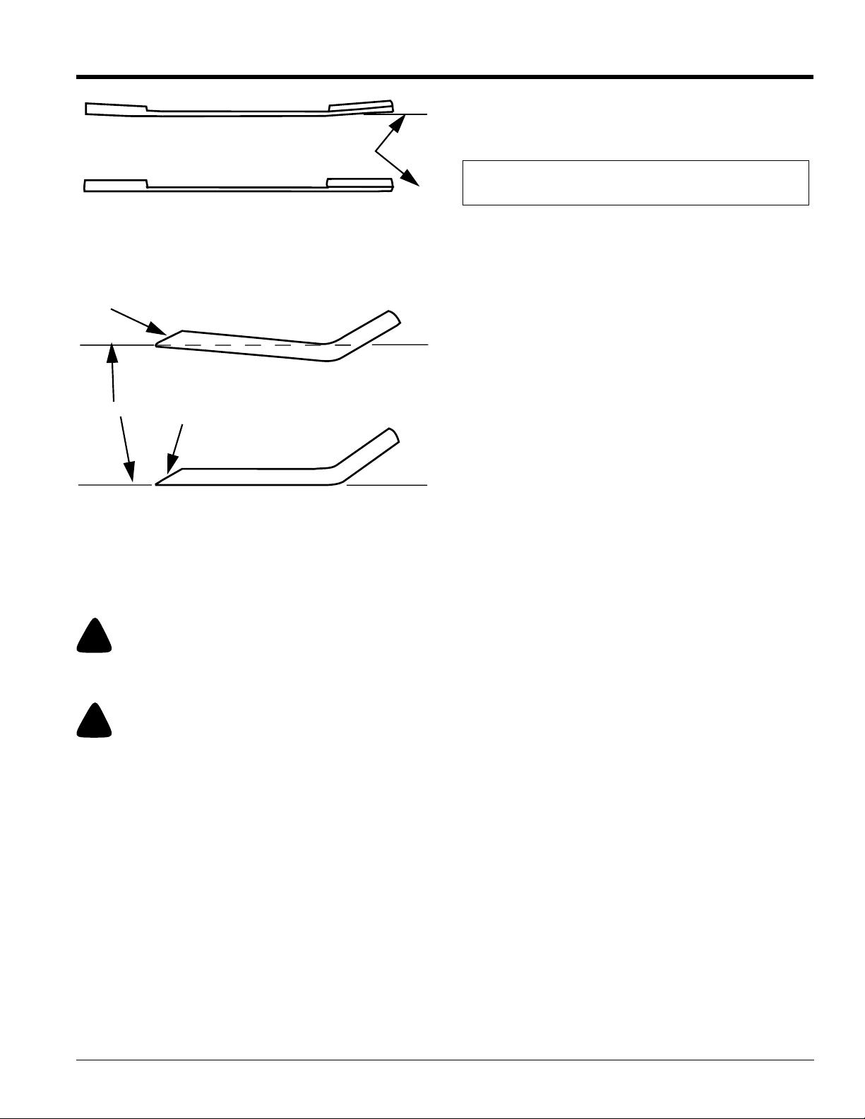
Land Pride
Section 4 Maintenance and Lubrication
Warped Blade (Replace)
Cutting Plane
19076
Comparison of Warped and Straight Blades
Cutting Edge
Cutting Plane
19077
End View of Blades, Twisted & Straight Blades
Do not re-use spindle bolts which have stripped, worn or
undercut threads. Refer to “Torque Values Chart” on
page 44 when replacing hardware for proper torque.
!
WARNING!
When mounting blades, rotate them after installation to ensure
blade tips do not touch each other or sides of the mower.
!
WARNING!
Failure to correctly torque the bolt may result in the loss of the
blade which can cause serious injury.
Straight Blade
Figure 4-14
Twisted Blade Edge (Replace)
Cutting Edge
Straight Blade Edge
Figure 4-15
STORAGE
When storing the unit at the end of the mowing season,
the following steps should be taken to ensure readiness
for the next mowing season.
1. Removeall grass, dirt, and trash.Clean and touch up
all scrapes with Land Pride spray paint.
2. Cleanpaper air filter.Replace if necessary. Washand
re-oil foam pre-cleaner.
3. Checkthoroughly for any worn or damaged parts that
need replacing and order them from your dealer.
4. Thoroughly lubricate machine, according to
lubrication instructions.
5. Checkhydraulicoil level.Addoil if necessary. Change
oil and filter if not done in last 500 hours. Lubrizol
additive is required. Refer to Maintenance section.
6. Block mower up so weight is off tires.
NOTE: Do not deflate tires.
7. Protect battery from freezing temperatures.
Occasionally recharging battery during storage will
extend battery life.
8. Perform separate engine preparation as listed below.
9. Store mower in a clean, dry place.
Preparation of Engine for Storage
When engine is to be unused for long periods, proceed as
follows:
1. Run engine for a minimum of 15 minutes.
2. Drain oil from crankcase while engine is still warm.
3. Refill with fresh oil of proper viscosity.
4. Drain fuel tank and run the engine until it stops from
lackoffuel. Gasoline evaporatesif leftin carburetorfor
long periods, forming gum and varnish deposits in
carburetor. These deposits will cause engine flooding
and loss of power.
5. Remove and replace fuel filter if not done in previous
100 hours.
6. Removespark plugs and pour a tablespoon of engine
oil into each spark plug hole. Install plugs, but do not
reconnect plug leads.
7. Crank engine with starter at least a dozenrevolutions
to distribute oil over cylinder walls and valve
mechanism.
8. Clean exterior surfaceof engine. Spread a light film of
oiloverany exposedmetal surfacesof enginethat are
subject to corrosion.
9. Clean dirt and chaff from cylinders and fins, blower
housing and muffler.
10. Check oil filler cap and fuel tank cap to make certain
they are securely in place.
New Season Preparation
Before starting the mower following post season storage,
the following servicing is required:
1. Clean mower, removing trash and dirt accumulation.
2. Check engine oil and hydraulic oil levels.
3. Fill fuel tank with fresh gasoline. Run machine at half
speed for 5 minutes, checking operation of steering
control levers. Stop engine and check for oil leaks,
loose fittings and so forth.
4. Tighten any bolts that have loosened and make sure
all hair pins, cotter pins and clevis pins are in place.
5. Install all safety shields and review safetyprecautions
listed in this manual.
6. Check and inflate tires to 8-12 psi.
7. Reconnect spark plug leads to spark plug.
03/11/03
Z52®, Z60® & Z72® Zero Turning Radius Mowers Accu-Z 356-005M
39
Page 42

Section 5 Specifications and Capacities
Section 5 Specifications and Capacities
Engine Specifications
Kawasaki Kawasaki Honda
Horsepower
No. of Cylinders
Displacement
Compression Ratio
Max T orque
Oil Capacity
23 25 24
222
41.2 cu. in. (675cc) 41.2 cu. in. (675cc) 40.9 cu. in. (670cc)
8.1:1 8.1:1 8.3:1
39.8 FT. LBS @ 2400 RPM 41.2 FT. LBS @ 2400 RPM 37.5 FT. LBS @ 2500 RPM
2 US quarts 2 US quarts 1.8 US quarts
General Specifications
Height
Length
Width of Cut
Overall width
Weight
Drive tires
Front Tires
Tire-to-tire width:
Starter
Ignition
Charging System
Governor
Cooling
Fuel
Fuel capacities
Fuel Filter
Traction Drive Type
Hydraulic Drive oil
Hydraulic Oil Capacity
Hydraulic Pumps
Hydraulic Filter
Hydraulic Pump Drive
Final Drive
Ground Speed
Steering Type
Twin Lever Steering Controls
Steering Turning Radius
Brake Type
23 x 9.50 - 12, turf tread 24 x 12.00 - 12, turf tread 24 x 12.00 - 12, turf tread
True zero degree. Turns within its own length with counter-rotating independent drive wheels
Land Pride
Z52 Z60 Z72
39”
76"
52" 60" 72"
64" 65" 82 1/2"
1,065 lbs. 1,100 lbs. 1,230 lbs.
13 x 6.5 - 6, rib tread
53"
12-volt (.8 KW), solenoid shift positive engagement.
Electronic
Kawasaki: 12-volt, 15 amp
Honda: 12-volt, 20 amp
Mechanical
Kawasaki: Air cooled, Fly-wheel fan
Honda: Air cooled, Fly-wheel fan with oil cooler
Unleaded gasoline with octane rating of 87 or higher
12 US GAL
Replaceable, automotive-type
Dual Hydrostatic Transmission
10W40 motor oil
1.5 US GAL (7.57 L)
Two Hydro-Gear® BDP10 variable displacement, axial piston type.
40 micron, Replaceable spin-on type
V-belt drive from engine crankshaft
Ross MB15 direct-drive high-torque wheel motors for each drive wheel.
Forward: 0-11 MPH
Reverse: 0-5 MPH
Twin lever steering provides independent control of each drive wheel.
Speed, forward, reverse, brake, and turns.
Hydrostatic dynamic braking
Z52®, Z60® & Z72® Zero Turning Radius Mowers Accu-Z 356-005M 03/11/03
40
Page 43

Land Pride
Section 5 Specifications and Capacities
General Specifications
Parking
Mower Drive
Safety Features
Seat
Cup Holder
Hand Operated Controls
Indicators
Cutting Heights
Mowing Blades
Blade Tip Speed
Blade Drive
Spindles
Flotation
Mainframe Construction
Drive motor mount
Caster wheels
Front caster forks
Deck T ype
Deck Lift
Deck Construction
Integral park brakes are automatically engaged when steering levers are placed in neutral.
Standard: Molded-vinyl seat with armrests, forward adjustments, and reverse adjustment.
Choke/throttle, ignition switch, electric mower clutch and Integrated parking brakes.
Foot-operated deck height adjustment. Pin for setting height, transport position. Height
1/4" x 2 3/4" x 17.8" 1/4" x 2 3/4" x 21" 1/4" x 2 3/4" x 24"
16,647 FPM 18, 30 FPM 18880 FPM
Machine ductile housing, 1" diameter high carbon steel shafts and sealed ball bearings. Cast
Suspended mower floats on four spring-assisted chains. 4 anti-scalp wheels are standard.
Free-floatingmower using three blades with center blade to the front. Mower is suspended at
the corners. Includes 6 deck-mounted anti-scalp rollers to improve flotation in rolling and
1/8” welded steel. Solid 1” X 3/8” steel bars reinforce impact areas on trim edges. 3/16” x 3/8”
in box-section reinforced front edge. Reinforcements welded onto spindle mount areas. Steel
Z52 Z60 Z72
Automotive-style drum brakes.
Single V-belt with electric clutch and spring tension idler pulley
Operator presence system connected to deck and drive clutches.
Stabilizer rollers rear of tractor.
Optional: Molded-vinyl suspension seat with armrests, forward adjustments,
Reverse adjustments, and suspension adjustments.
Two cup holders molded into the left side fuel tank.
Accommodates nearly any cup size.
Hour meter
Engine warning light.
adjustment in 1/4" increments from 1" to 5"
Heavy-duty, heat-treated, high-lift steel blades
V-belt drive to all three spindles with spring tension idler pulleys.
ductile cast iron blade saddles with trash guard.
1.5" x 3" x 3/16" rectangular steel tubing.
3/16" welded steel
Mounted with roller bearings on each wheel.
1/2" steel.
uneven terrain.
Foot-operated deck height adjustment.
Pin for setting height, transport position.
deck housing is 5” deep to provide room for high-capacity mowing.
ACCESSORIES
Mulch Kit
Recycles clippings under deck allowing clippings to be cut and recut, then discharged down into the grass. Reduces
handling of clippings, improves appearance, and recycles nutrients back into the soil.
Accu-Vac Collection System
Four blade impeller running off right hand deck spindle, 2 each 30 gallon rubber containers, 8.0 cu/ft. (10 bushel)
capacity, 6” reinforced hose, latched hood with gas filled lift support, three pin quick dismount of total unit, 100 lb. weight
kit. Adds 1 3/16” width to existing Accu-Z. Adds 24” to rear of Accu-Z. Accu-Vac length: 31”, Width: 34”, Height: 41 7/8”
Lift Jack Kit
Easy to mount screw jack to lift mower enough to perform blade removal/installation.
Weight Kit
100 lb. front weight kit standard with Accu-Vac Collection System.
03/11/03
Z52®, Z60® & Z72® Zero Turning Radius Mowers Accu-Z 356-005M
41
Page 44

Section 6 Features and Benefits
Section 6 Features and Benefits
Land Pride
Features
Benefits
52”, 60” or 72” Cutting width Mostpopular cutting widths for upper homeowner market and entry into light commercial
market.
Mid-mount deck design Mid-mount design puts the deck closer to the operator’s line of sight for a more efficient
and precise operation.
Compact size 76” in length, is the shortest ZTR on the market. Enhances mowing maneuverability, as
well as fitting on trailers or storing more efficiently.
53” Drive tire stance Narrow width allows for tight turns in corners, yet gives a very stable platform for the
operator.
Steering levers Dual steering levers which control each drive wheel, have a shape and position that is
very user friendly, hand and arm fatigue are greatly minimized.
3/16” Deck w/ 3/8” reinforcement One of the heaviest built decks in the industry for years of rigorous use. Reinforced front
edge where most of the punishment happens.
Floating deck design Deck has a spring assisted chain suspension which offers excellent flotation over uneven
terrain.
Deck height adjustment Height is changed by a spring-loaded foot operated lever and pin. Easy to push and
faster than waiting on an electric actuation.
Anti-scalp rollers Front and four corners to keep scalping to a minimum.
Cutting height 1” to 5” Range in 1/4” increments to cut any type of turf grass.
High blade tip speed 18,700 fpm Assures a good finish cut.
High lift blades Heavy-duty 1/4” high lift blades are thick to handle the wear, with a high lift design to
stand the grass up before cutting.
Mulching kit A mulching kit is available to recycle clippings and discharge them down into the grass.
1” Blade spindles 1” Blades spindles with sealed ball bearings handle heavy shock loads.
Single belt drive Single belt design offers easier maintenance over multiple belt designs, less expensive
to maintain.
Electric clutch control Easy and smooth engagement of the mower blade drive system.
Parking Brake & Safety Lockout Drum brakes and safety lockout are engaged when steering levers are placed in neutral,
does not require a separate operation to place in neutral. One less thing to look for if
mower does not start
Drive Each rear drive wheel has a separate hydrostatic pump & direct drive motor.
Electric start Easily starts with the turn of a key.
Engine hour meter Helps in determining maintenance schedules and trade-in values.
12 gallon fuel capacity Less down time.
Easy engine maintenance Engine is mounted so that all of the maintenance items can be serviced from the rear of
the mower vs. the side.
No daily lube points Blade spindles require grease only once a year. Sealed bearings on front caster wheel
forks.
Molded vinyl seat Molded seat incorporates a high back and armrests to give extra comfort for the long
jobs.
Molded-in cup holders Easy to reach cup holders fit a wide variety of cups, and are in easy access to driver.
Steering lever extensions For extra comfort for the larger person. Add the extensions to give more leg room.
Floating deck design Deck has a spring assisted chain suspension which offers excellent flotation over uneven
terrain.
Deck height adjustment Height is changed by a spring-loaded foot operated lever and pin. Easy to push and
faster than waiting on an electric actuation.
Z52®, Z60® & Z72® Zero Turning Radius Mowers Accu-Z 356-005M 03/11/03
42
Page 45

Land Pride
Section 7 Troubleshooting
Section 7
Troubleshooting
Symptoms Probable Causes Suggested Remedies
Starting motor does not crank
Engine cranks but does not start
Engine:
Runs with continuous misfiring or
engine runs unevenly or erratically
Loss of power or system will not operate
in either direction
Overheating
Control handles not in park brake
position (out) or switch not adjusted
Mower clutch switch engaged Disengage clutch switch
Weak or dead battery Recharge or replace
For additional causes See engine manual
No fuel or line plugged Fill tank or replace line
Numerous See engine manual
Numerous See engine manual
Restrictions in air cleaner Service air cleaner
Hydraulic line blockage See your dealer
Internal interference or leakage in
wheel motor
Insufficient hydraulic oil supply Check level in reservoir
Poor compression See your dealer
Steering linkage needs adjustment Adjust linkage
Air in system Check filter & fittings
For additional causes See engine manual
Air intake screen or cleaning fins
clogged
Place control handle in park brake
position or re-adjust switch
See your dealer
Have dealer check hydraulic pump
Clean screen and fin
Low oil pressure
High oil consumption
Mowerjerky when starting or operates in
one direction only
Hydraulic system operates hot (oil in
reservoir smells rancid)
Mower creeps when steering control
levers are in neutral
Mower circles or veer s in one direction
Mower creeps when parking brake
engaged
For additional causes See engine manual
Low oil level Add oil
Oil diluted or too light Change oil and check for source of
Numerous See your dealer
Steering control linkage needs
adjustment
Pump or wheel motors faulty See your dealer
Low hydraulic oil level Fill reservoir
Hydraulic pump faulty See your dealer
Steering linkage needs adjustment Adjust linkage
Steering linkage needs adjustment Adjust linkage
Wheel motors faulty See your dealer
Hydraulic pump faulty See your dealer
Steering linkage needs adjustment Adjust steering linkage
Brakes need adjustment Adjust parking brakes
contamination
Adjust linkage
03/11/03
Z52®, Z60® & Z72® Zero Turning Radius Mowers Accu-Z 356-005M
43
Page 46
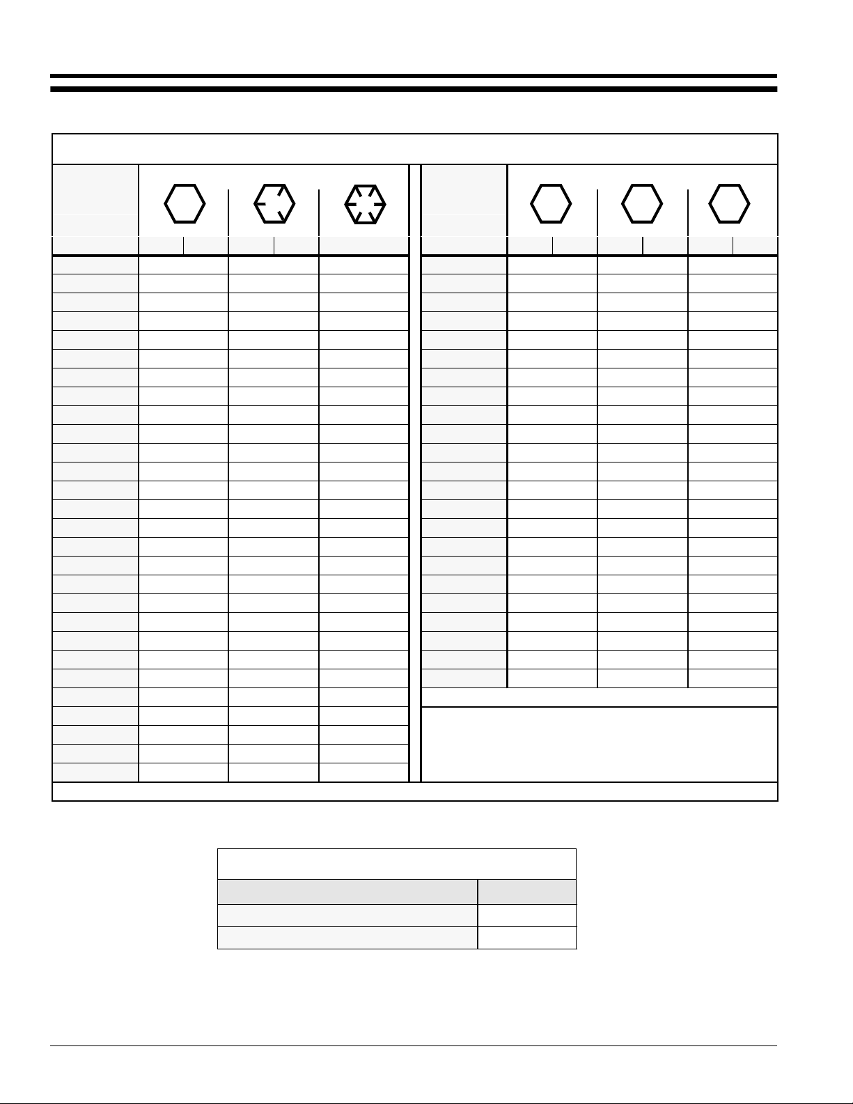
Section 8 Appendix
Section 8
Appendix
Torque Values Chart for Common Bolt Sizes
Land Pride
Bolt Head Identification
Bolt Size
(Inches)
1
in-tpi
1/4" - 20 7.4 5.6 11 8 16 12 M 5 X 0.8 436597
1/4" - 28 8.5 6 13 10 18 14 M 6 X 1 7 5 11 8 15 11
5/16" - 18 15 11 24 17 33 25 M 8 X 1.25 17 12 26 19 36 27
5/16" - 24 17 13 26 19 37 27 M 8 X 1 18 13 28 21 39 29
3/8" - 16 27 20 42 31 59 44 M10 X 1.5 33 24 52 39 72 53
3/8" - 24 31 22 47 35 67 49 M10 X 0.75 39 29 61 45 85 62
7/16" - 14 43 32 67 49 95 70 M12 X 1.75 58 42 91 67 125 93
7/16" - 20 49 36 75 55 105 78 M12 X 1.5 60 44 95 70 130 97
1/2" - 13 66 49 105 76 145 105 M12 X 1 90 66 105 77 145 105
1/2" - 20 75 55 115 85 165 120 M14 X 2 92 68 145 105 200 150
9/16" - 12 95 70 150 110 210 155 M14 X 1.5 99 73 155 115 215 160
9/16" - 18 105 79 165 120 235 170 M16 X 2 145 105 225 165 315 230
5/8" - 11 130 97 205 150 285 210 M16 X 1.5 155 115 240 180 335 245
5/8" - 18 150 110 230 170 325 240 M18 X 2.5 195 145 310 230 405 300
3/4" - 10 235 170 360 265 510 375 M18 X 1.5 220 165 350 260 485 355
3/4" - 16 260 190 405 295 570 420 M20 X 2.5 280 205 440 325 610 450
7/8" - 9 225 165 585 430 820 605 M20 X 1.5 310 230 650 480 900 665
7/8" - 14 250 185 640 475 905 670 M24 X 3 480 355 760 560 1050 780
1" - 8 340 250 875 645 1230 910 M24 X 2 525 390 830 610 1150 845
1" - 12 370 275 955 705 1350 995 M30 X 3.5 960 705 1510 1120 2100 1550
1-1/8" - 7 480 355 1080 795 1750 1290 M30 X 2 1060 785 1680 1240 2320 1710
1 1/8" - 12 540 395 1210 890 1960 1440 M36 X 3.5 1730 1270 2650 1950 3660 2700
1 1/4" - 7 680 500 1520 1120 2460 1820 M36 X 2 1880 1380 2960 2190 4100 3220
1 1/4" - 12 750 555 1680 1240 2730 2010
1 3/8" - 6 890 655 1990 1470 3230 23801 in-tpi = nominal thread dia. in inches-threads per inch
1 3/8" - 12 1010 745 2270 1670 3680 2710
1 1/2" - 6 1180 870 2640 1950 4290 31603 ft-lb= foot pounds
1 1/2" - 12 1330 980 2970 2190 4820 3560
Grade 2 Grade 5
N · m2ft-lb3N · m ft-lb N · m ft-lb mm x pitch
Grade 8
Bolt Size
(Metric)
4
N · m ft-lb N · m ft-lb N · m ft-lb
2
N· m = newton-meters
4
mm x pitch = nominal thread dia. in millimeters x thread pitch
Bolt Head Identification
5.8 8.8 10.9
Class 5.8 Class 8.8 Class 10.9
Torque tolerance + 0%, -15% of torquing values. Unless otherwise specified use torque values listed above.
Tire Inflation Chart
Tire Inflation PSI
Drive Wheels 8-12
Gauge Wheels 8-12
Z52®, Z60® & Z72® Zero Turning Radius Mowers Accu-Z 356-005M 03/11/03
44
Page 47

Land Pride
Section 8 Appendix
be free from defects in material and workmanship beginning on the date of
purchase by the end user according to the following schedule when used as
intended and under normal service and conditions for personal use.
and the installation by the dealer of any such replacement part, and does not cover
common wear items such as blades, belts, tines, etc. Land Pride reserves the right
to inspect any equipment or parts which are claimed to have been defective in
material or workmanship.
judgment shall have been misused or damaged by accident or lack of normal
maintenance or care, or which has been repaired or altered in a way which
adversely affects its performance or reliability, or which has been used for a
purpose for which the product is not designed. Misuse also specifically includes
failure to properly maintain oil levels, grease points, and driveline shafts.
the product and all warranty adjustments must be made through such dealer. Any
action for breach of warranty must be commenced within 25 months following
delivery in non-rented application, and within 120 days following delivery in rented
application.
of any kind, direct, consequential, or contingent to property. Furthermore, Land
Pride shall not be liable for damages resulting from any cause beyond its
reasonable control. This Warranty does not extend to loss of crops, any expense
or loss for labor, supplies, rental machinery or for any other reason.
respect to this sale; and all implied warranties of merchantability and fitness for a
particular purpose which exceed the obligations set forth in this written warranty
are hereby disclaimed and excluded from this sale.
the date of purchase by the end user.
Warranty
Land Pride warrants to the original purchaser that this Land Pride product will
Overall unit: 2 years or 1200 hours limited warranty on parts and labor,
whichever comes first.
Engine: 2 years limited warranty through Engine manufacturer.
Hydraulic Wheel Motors and Pumps: 2 years on Parts and Labor.
Front Edge of Mower Deck: Limited warranty against all defects in the deck
which results in the front edge of the deck being bent into the blades for the
entire length of ownership by the original purchaser.
Frame: Frame breakage through the entire length of ownership by the original
purchaser.
Blade Spindle: 3 years or 1200 hours Parts and Labor.
Front Gauge Wheel Yoke Bearings: 3 years or 1200 hours Parts and Labor
Battery: 1 year limited warranty.
Rental Units: Limited warranty on all materials and workmanship for a period of
90 days.
Belts, blades, and tires are considered wear items.
Filters and Plugs are considered maintenance items.
This Warranty is limited to the replacement of any defective part by Land Pride
This Warranty does not apply to any part or product which in Land Pride’s
Claims under this Warranty must be made to the dealer which originally sold
This Warranty shall not be interpreted to render Land Pride liable for damages
No other warranty of any kind whatsoever, express or implied, is made with
This Warranty is not valid unless registered with Land Pride within 30 days from
03/11/03
Z52®, Z60® & Z72® Zero Turning Radius Mowers Accu-Z 356-005M
45
Page 48

Corporate Office: P.O. Box 5060
Salina, Kansas 67402-5060 USA
www.landpride.com
 Loading...