

Land Pride Accu-Z Razor ZSR54, Accu-Z Razor ZSR60 Service Manual
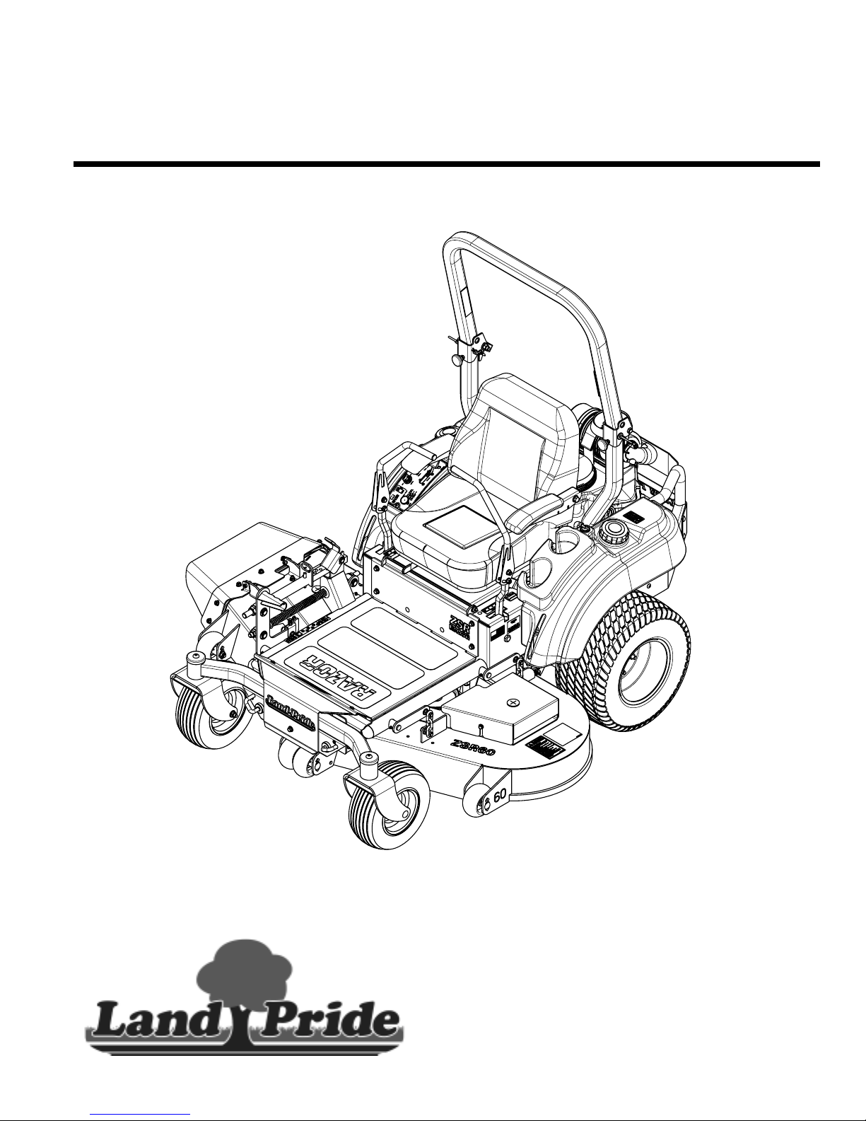
Table of Contents
Zero Turn Mowers
ZSR54 & ZSR60 Accu-Z Razor
®
27800
357-388SM
Service Manual
© Copyright 2012 Printed
7/30/12

Table of Contents
Table of Contents
Section 1: Operator Controls . . . . . . . . . . .4
Steering Arm Removal . . . . . . . . . . . . . . . . . . . . . .4
Steering Arm Installation . . . . . . . . . . . . . . . . . . . .4
Control Arm and Lever Removal . . . . . . . . . . . . . . 5
Control Arm and Lever Installation . . . . . . . . . . . . .6
Park Brake Removal . . . . . . . . . . . . . . . . . . . . . . . 7
Park Brake Installation . . . . . . . . . . . . . . . . . . . . . . 8
Deck Lift Removal . . . . . . . . . . . . . . . . . . . . . . . . .9
Deck Lift Installation . . . . . . . . . . . . . . . . . . . . . . .10
Control Panel Removal . . . . . . . . . . . . . . . . . . . . 11
Control Panel Installation . . . . . . . . . . . . . . . . . . . 12
Section 2: Seat & Frame . . . . . . . . . . . . . .13
Seat and Latch Removal . . . . . . . . . . . . . . . . . . . 13
Seat and Latch Installation . . . . . . . . . . . . . . . . . 14
Floor Panel Removal . . . . . . . . . . . . . . . . . . . . . . 15
Floor Panel Installation . . . . . . . . . . . . . . . . . . . . 15
Engine Bumper Guard Removal . . . . . . . . . . . . . 16
Engine Bumper Guard Installation . . . . . . . . . . . . 16
Section 3: Mower Deck . . . . . . . . . . . . . . .17
Deck Removal . . . . . . . . . . . . . . . . . . . . . . . . . . . 17
Deck installation . . . . . . . . . . . . . . . . . . . . . . . . . 18
Pulley and Blade Hub Removal . . . . . . . . . . . . . . 19
Pulley and Blade Hub Installation . . . . . . . . . . . . 19
Spindle Hub Rebuild . . . . . . . . . . . . . . . . . . . . . .20
Section 4: Electrical System . . . . . . . . . .22
Battery Assembly Removal . . . . . . . . . . . . . . . . . 22
Battery Assembly Installation . . . . . . . . . . . . . . . . 22
Wiring Harness Removal . . . . . . . . . . . . . . . . . . . 23
Wiring Harness Installation . . . . . . . . . . . . . . . . . 24
Main Harness Wiring Schematics . . . . . . . . . . . . 25
Engine Wiring Schematics . . . . . . . . . . . . . . . . . .26
Section 5: Fuel System . . . . . . . . . . . . . .27
Fuel Valve and Hose Removal . . . . . . . . . . . . . . . 27
Fuel Valve and Hose Installation . . . . . . . . . . . . .28
Fuel Tank Removal . . . . . . . . . . . . . . . . . . . . . . . 29
Fuel Tank Installation . . . . . . . . . . . . . . . . . . . . . . 30
Section 6: Wheels . . . . . . . . . . . . . . . . . . .31
Front Caster Wheel Removal . . . . . . . . . . . . . . . .31
Front Caster Wheel Installation . . . . . . . . . . . . . . 32
Front Axle Removal . . . . . . . . . . . . . . . . . . . . . . .33
Front Axle Installation . . . . . . . . . . . . . . . . . . . . . .34
Rear Drive Wheel Removal . . . . . . . . . . . . . . . . .35
Rear Drive Wheel Installation . . . . . . . . . . . . . . . .35
Section 7: Power Train . . . . . . . . . . . . . . . 36
Muffler Removal . . . . . . . . . . . . . . . . . . . . . . . . . .36
Muffler Installation . . . . . . . . . . . . . . . . . . . . . . . .36
Engine Removal . . . . . . . . . . . . . . . . . . . . . . . . . .37
Engine Installation . . . . . . . . . . . . . . . . . . . . . . . .38
Clutch Removal . . . . . . . . . . . . . . . . . . . . . . . . . .39
Clutch Installation . . . . . . . . . . . . . . . . . . . . . . . . .40
Transaxle Removal . . . . . . . . . . . . . . . . . . . . . . .41
Transaxle Installation . . . . . . . . . . . . . . . . . . . . . .43
Section 8: Adjustments . . . . . . . . . . . . . .46
Torque Requirements . . . . . . . . . . . . . . . . . . . . .46
Tire Pressure . . . . . . . . . . . . . . . . . . . . . . . . . . . .46
Front Floating Axle
(ZSR Models Only) . . . . . . . . . . . . . . . . . . . . . . . .46
Steering Adjustments . . . . . . . . . . . . . . . . . . . . . .47
Lower Control Lever . . . . . . . . . . . . . . . . . . . .47
Upper Control Lever . . . . . . . . . . . . . . . . . . . .48
Seat Adjustment . . . . . . . . . . . . . . . . . . . . . . . . . .48
Ground Drive Belt Adjustment . . . . . . . . . . . . . . .49
Deck Drive Belt Adjustment . . . . . . . . . . . . . . . . .49
Deck Adjustments . . . . . . . . . . . . . . . . . . . . . . . .50
Deck Cutting Height And Leveling . . . . . . . . . .50
Deck Lift Assist Springs . . . . . . . . . . . . . . . . . .51
Anti-Scalp Rollers . . . . . . . . . . . . . . . . . . . . . .52
Cutting Height Settings . . . . . . . . . . . . . . . . . . . .52
Section 8: Maintenance & Lubrication . . 54
Maintenance . . . . . . . . . . . . . . . . . . . . . . . . . . . .54
Maintenance Safety . . . . . . . . . . . . . . . . . . . . . . .54
Maintenance Locations . . . . . . . . . . . . . . . . . . . .56
Torque Requirements . . . . . . . . . . . . . . . . . . . . .58
© Copyright 2012 All rights Reserved
Land Pridepro videsthis publication “asis” without warrantyof any kind,eitherexpressed orimplied.While every precautionhas been takenin the preparationofthis manual, Land
Pride assumesno responsibility f orerrors oromissions .Neither isany liability assumedfor damagesresulting from theuse of theinformation containedherein.Land Pridereserves
the rightto reviseandimprove itsproducts as itsees fit. Thispublication describes thestate of thisproduct at thetime of itspublication, andmay not reflectthe product inthe future.
All otherbrands and product namesare trademarks or registeredtrademarksof their respectiveholders.
ZSR54 & ZSR60 Accu-Z Razor® Zero Turn Mowers 357-388SM
Land Pride isa registered trademark.
Printed in the United StatesofAmerica.
1/20/12

Table of Contents
Table of Contents
Tires . . . . . . . . . . . . . . . . . . . . . . . . . . . . . . . . . . 58
Electrical System . . . . . . . . . . . . . . . . . . . . . . . . . 59
Hydrostatic Drive System . . . . . . . . . . . . . . . . . . 60
Hydraulic Oil Level Check . . . . . . . . . . . . . . . . . . 60
Transaxle Oil and Filter Change . . . . . . . . . . . . . 60
Transaxle Purging Procedures . . . . . . . . . . . . . . 61
Fuel System . . . . . . . . . . . . . . . . . . . . . . . . . . . . 62
Evaporative Emission Control System . . . . . . . . . 63
Fuel Filter . . . . . . . . . . . . . . . . . . . . . . . . . . . . . . 63
Draining The Fuel Tank . . . . . . . . . . . . . . . . . . . . 63
Belt Maintenance . . . . . . . . . . . . . . . . . . . . . . . . . 64
Deck Drive Belt Removal & Installation . . . . . . 64
Ground Drive Belt Removal & Installation . . . . 64
Mower Blade Maintenance . . . . . . . . . . . . . . . . . 66
General Engine Maintenance . . . . . . . . . . . . . . . 68
Engine Oil and Oil Filter . . . . . . . . . . . . . . . . . . . . 68
Check Engine Oil . . . . . . . . . . . . . . . . . . . . . . 68
Change Engine Oil . . . . . . . . . . . . . . . . . . . . . 68
Engine Air Filter . . . . . . . . . . . . . . . . . . . . . . . . . . 69
Internal Type Air Filters . . . . . . . . . . . . . . . . . . 69
Canister Type Air Filters . . . . . . . . . . . . . . . . . 69
Air Filter Handling . . . . . . . . . . . . . . . . . . . . . . . . 70
End of Season & Long Term Storage . . . . . . . . . 71
New Season Preparation . . . . . . . . . . . . . . . . . . . 71
Lubrication Points . . . . . . . . . . . . . . . . . . . . . . . . 72
Section 10: Troubleshooting . . . . . . . . . 74
Section 11: Appendix . . . . . . . . . . . . . . . 76
Engine Specifications . . . . . . . . . . . . . . . . . . . . . 76
Hydrostatic Transaxle Specifications . . . . . . . . . . 76
General Specifications . . . . . . . . . . . . . . . . . . . . . 76
ZSR54 & ZSR60 Zero Turn Mowers . . . . . . . . . . 78
Additional Torque Values . . . . . . . . . . . . . . . . . . 79
1/20/12
ZSR54 & ZSR60 Accu-Z Razor® Zero Turn Mowers 357-388SM
3
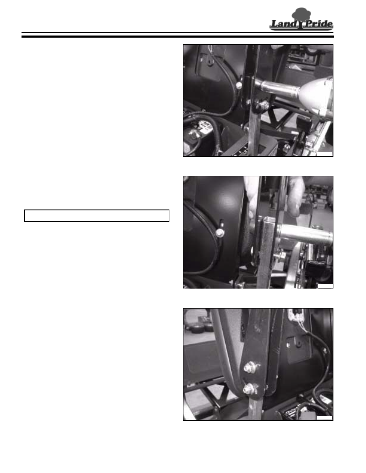
Table of Contents
Section 1: Operator Controls
Section 1: Operator Controls
Steering Arm Removal
Refer to Figure 1-1:
1. Loosen and removetwo steering arm retaining bolts.
2. Slide steering arm up and off of the drive control
stub.
3. Repeat steps 1 through 2 for other side.
Steering Arm Installation
Refer to Figure 1-2:
1. Slide steer ing arm to desired height and install pivot
bolt and nut.
33678
Figure 1-1
NOTE: Do not tighten at this time.
2. Install bolt and nut in arm adjustment slot.
3. Adjust arms to desired angle for operation.
Refer to Figure 1-3:
4. Tighten all fasteners to standard torque. See chart
on page 79.
5. Repeat steps 1 through 4 for other side.
33679
Figure 1-2
ZSR54 & ZSR60 Accu-Z Razor® Zero Turn Mowers 357-388SM
4
33680
Figure 1-3
7/30/12
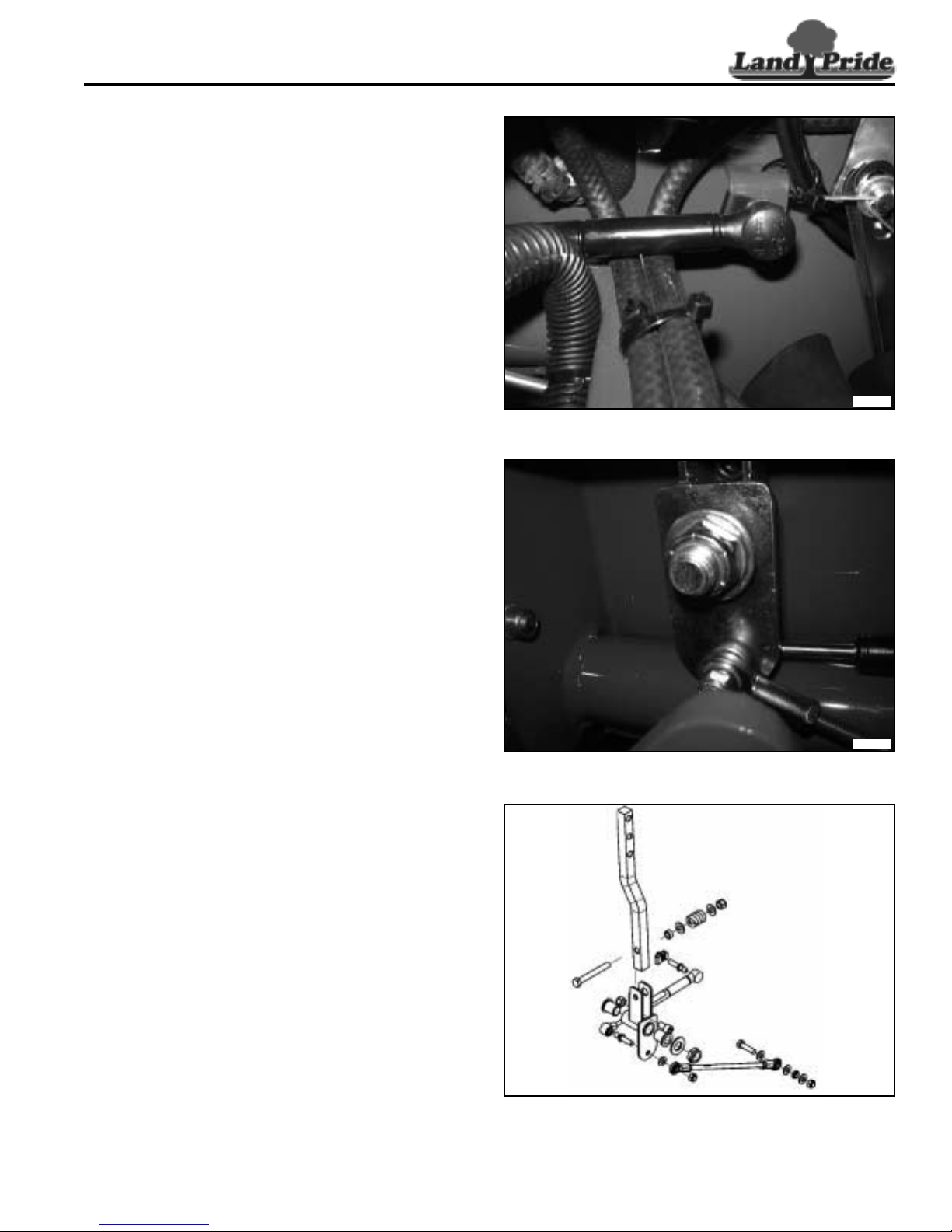
Table of Contents
Section 1: Operator Controls
Control Arm and Lever Removal
Refer to Figure 1-4:
1. Chock wheels to secure mower and prevent
movement while repairs are made.
2. Disconnect batter y to prevent accidental shock. See
“Battery Assembly Removal” on page 22.
3. Disconnect and remove seat pan assembly for easy
access.
4. Remove steering arm. See “Steering Arm
Removal” on page 4.
5. Unlock and remove retaining cap on the base end of
the control damper and remove from frame stud.
Refer to Figure 1-5:
6. Loosen and remove nut on the drive control rod
assembly and remove from steering lever.
7. Loosen and remove the steering lever retaining nut
and washer.
8. Remove steering lever bracket from frame mount
bolt. Ensure that the control arm is out in the brake
position and allow it to slide though the frame.
33681
Figure 1-4
Refer to Figure 1-6:
9. Unlock and remove retaining cap on the rod end of
the control damper and remove from the steering
lever stud.
10. Loosen and remove spring retaining nut and washer
from the control arm mount bolt.
11. Remove damper stud, pivot bushings, control arm
tension spring, and control arm from the steering
lever.
12. Repeat steps 4 through 11 for other side.
7/30/12
Figure 1-5
Figure 1-6
ZSR54 & ZSR60 Accu-Z Razor® Zero Turn Mowers 357-388SM
33682
33683
5
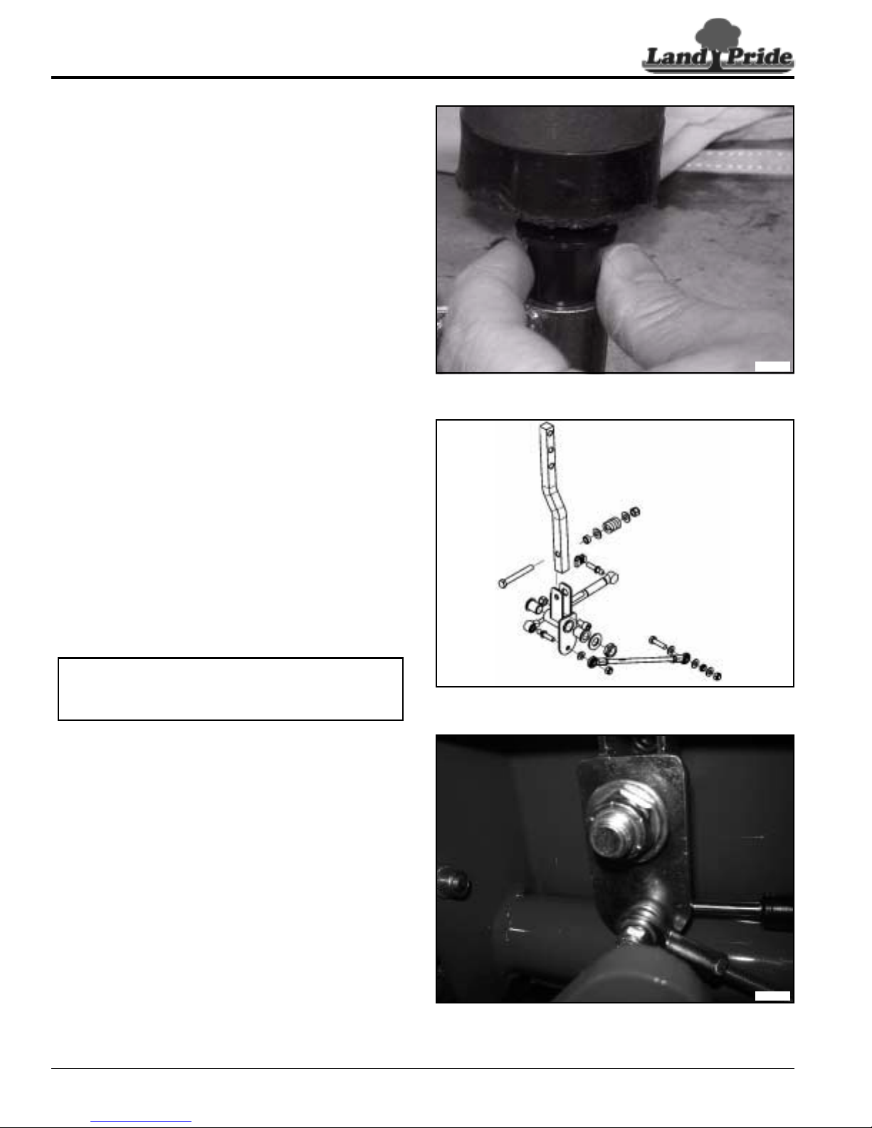
Table of Contents
Section 1: Operator Controls
Control Arm and Lever Installation
Refer to Figure 1-7:
1. Install flanged wear pivot bushings in both sides of
the control arm.
Refer to Figure 1-8:
2. Align and install the steering leveronthe control ar m
bolt.
3. Install the pivot washer, compression spring,
retaining washer and retaining lock nut.
4. Tightencompressionspringlocknut untilthreadsare
showing, may be adjusted to desired tension after
installation onto frame.
5. Install the damper stud into the rod end of the
damper and secure with retaining cap.
6. Insert threaded end of damper stud into the control
arm. The control rod retaining nut may be loosely
installed to aid in assembly.
33684
Figure 1-7
NOTE: Ensure correct alignment for left or right
hand side when inserting damper stud so that the
damper will be between frame and control arm.
Refer to Figure 1-9:
7. Push the control lever out into thebrakeposition and
insert though frame.
8. Align and install the control arm on the frame
mounting bolt, secure with retaining washerandlock
nut.
9. Tighten the steering arm retaining lock nut until tight,
then back off 1/8th of a turn to allow for free
movement of the steering arm.
10. Align and install the drive control rod assembly on
the threaded end of the control arm damper stud,
and secure with retaining lock nut.
11. Align and install base end of damper on frame stud
and secure with locking cap.
12. Install steering arm. See “Steering Arm
Installation” on page 4.
13. Repeat steps 1 though 12 for other side.
ZSR54 & ZSR60 Accu-Z Razor® Zero Turn Mowers 357-388SM
6
33683
Figure 1-8
33682
Figure 1-9
7/30/12
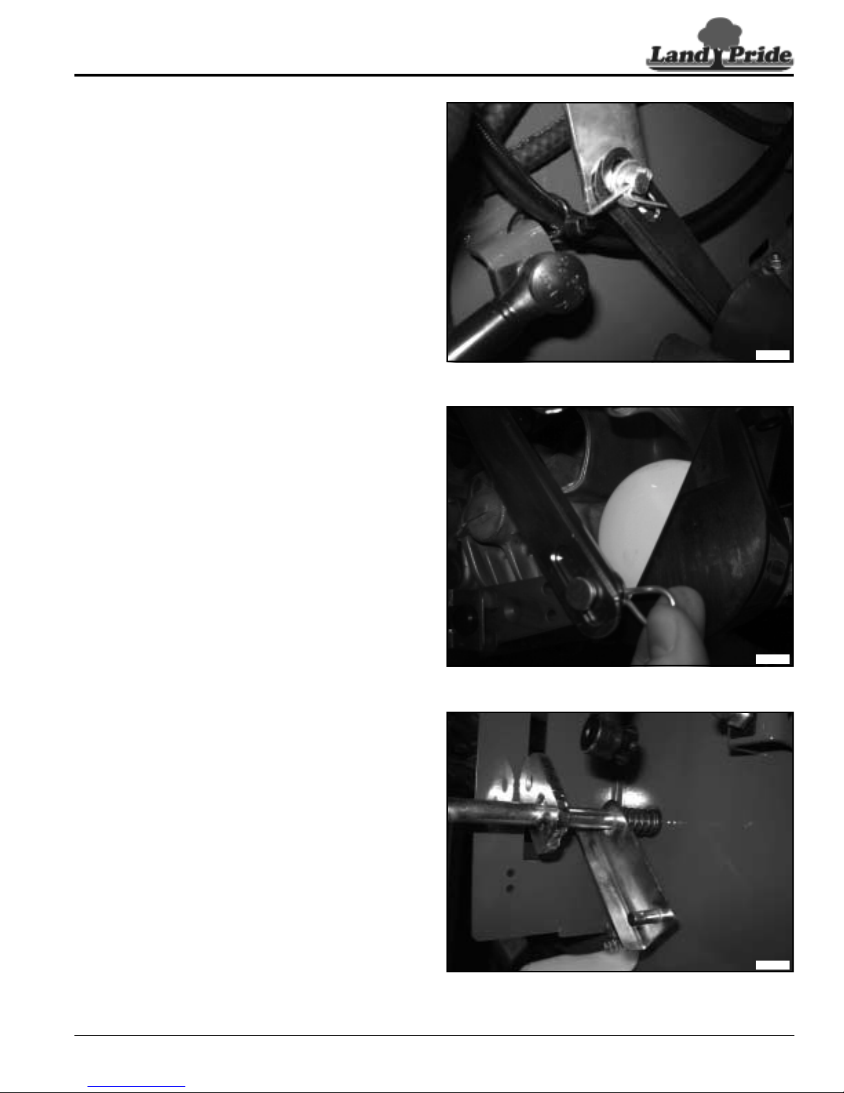
Table of Contents
Section 1: Operator Controls
Park Brake Removal
Refer to Figure 1-10:
1. Chock front wheels to secure mower and prevent
movement while repairs are made.
2. Disconnect batter y to prevent accidental shock. See
“Battery Assembly Removal” on page 22.
3. Raise and secure rear of mower and remove rear
wheels for easy access. See “Rear Drive Wheel
Removal” on page 35.
4. With park brake disengaged loosen and remove the
park brake handle retaining flanged lock nut.
Refer to Figure 1-11:
5. Removethecarter pin and retaining washer from the
upper end of the brake link spring assemblies.
6. Disconnectthebrakelinkspringassemblies from the
park lever pivot assembly.
7. Pull the hair pin clip and retaining washer from the
lower end of the brake link spring assemblies.
8. Disconnectthebrakelinkspringassemblies from the
trans-axle brake control levers.
33685
Figure 1-10
Refer to Figure 1-12:
9. Remove the park lever pivot assembly by pushing
the assembly to the left and compressing the
compression spring. Pull the right side of the pivot
assembly from the pivot bushing on the right hand
side and pull it up and out of the unit.
7/30/12
Figure 1-11
Figure 1-12
ZSR54 & ZSR60 Accu-Z Razor® Zero Turn Mowers 357-388SM
33686
33687
7
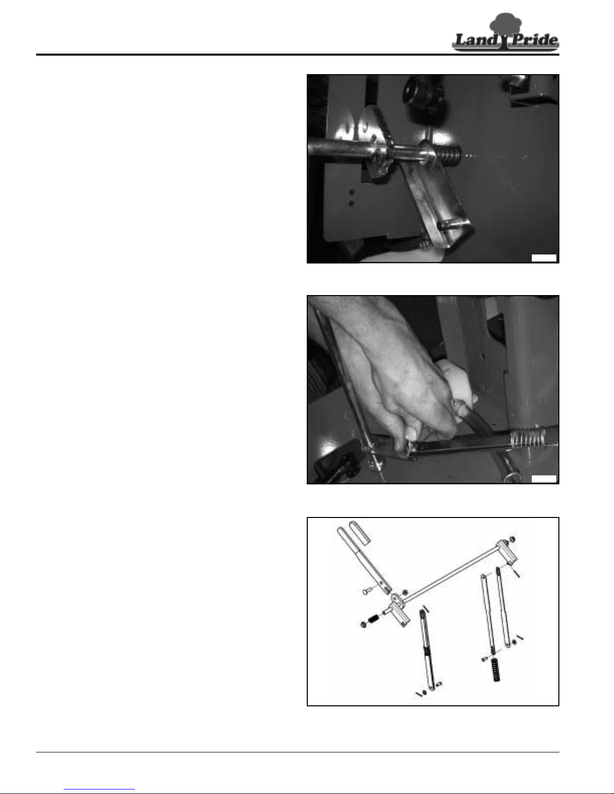
Table of Contents
Section 1: Operator Controls
Park Brake Installation
Refer to Figure 1-13:
1. Align and insert the park lever pivot bushings in the
unit frame.
2. Install compression spring on the brake handle lug
end of the park lever pivot assembly.
3. Align and install the park lever pivot assembly into
the frame by starting with the left hand side and
compressing the spr ing. Install the r ight hand side of
the park lever pivot assembly into the frame and
allow the spring to push into place.
Refer to Figure 1-14:
4. Assemble the brake link spring assemblies by
inserting a brake link into each end of the spring.
5. Align and install the brake link spring assemblies
down to the trans-axle brake lever and attach to the
park lever pivot assembly.
6. Secure both brake link spr ing assembliesto the park
lever pivot assembly with retaining washers and
carter pins.
33687
Figure 1-13
Refer to Figure 1-15:
7. Attachthebottomofthebrakelinkspringassemblies
to the trans-axle brake control levers.
8. Secure both brake link spring assemblies to the
trans-axle brake control levers with retaining
washers and hair pin clips.
9. Align and install the park brake handle though the
frame and secure with carriage bolt and flanged lock
nut.
ZSR54 & ZSR60 Accu-Z Razor® Zero Turn Mowers 357-388SM
8
33688
Figure 1-14
33689
Figure 1-15
7/30/12
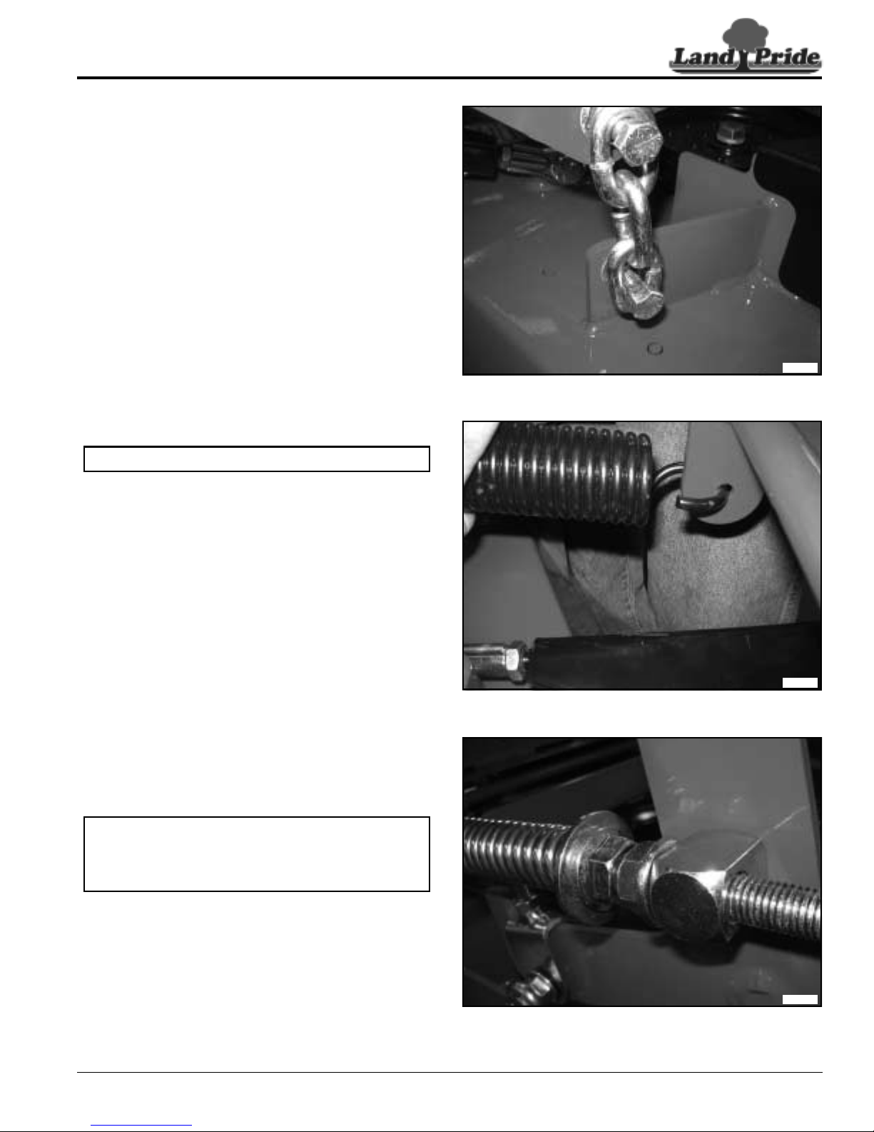
Table of Contents
Section 1: Operator Controls
Deck Lift Removal
Refer to Figure 1-16:
1. Chock wheels to secure mower and prevent
movement while repairs are made.
2. Remove the deck height stop from the height gauge
bar.
3. Place blocks under the mower deck and lower the
deck until the deck is fully supported by the blocks.
Refer to Figure 1-17:
33690
Figure 1-16
NOTE: Ensure that the deck chains are all slack.
4. Remove the E-clip from the height gauge bar
trunnion that attaches the height gauge bar to the
foot lift peddle and remove the height gauge bar
trunnion from the foot lift peddle.
5. Slide the height gauge bar out of the frame channel.
The height pawl will not need to be removed for
removal of the height gauge bar.
6. Disconnect and remove the deck lift assist spring
from the deck lift pivot.
Refer to Figure 1-18:
7. Remove the E-clips from both the front and rear of
the lift spring assembly trunnions.
NOTE: Springsare under compression against the
frame stop and front jam nut on the lift spring
assembly and care should be taken when
removing.
33691
Figure 1-17
8. Remove lift spring tr unnion from the front deck lift
armandloosenthenutsandmovethetrunniontothe
end of the spring rod.
9. Compress the spring assembly back to loosen and
removethe lift spr ing trunnion from the back decklift
arm.
10. Allow spring on the lift spring assembly to
uncompress and remove the lift spring assembly
through the slot in the frame stop
7/30/12
Figure 1-18
ZSR54 & ZSR60 Accu-Z Razor® Zero Turn Mowers 357-388SM
33692
9
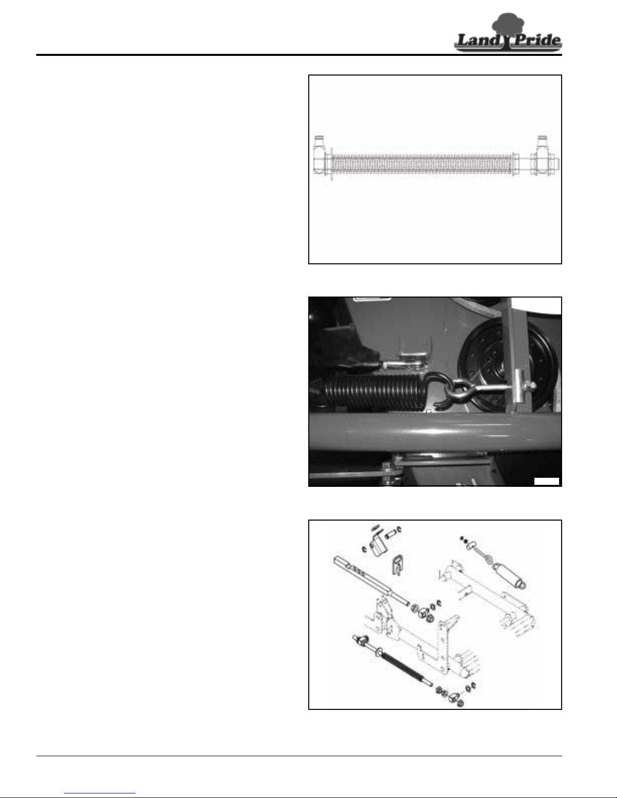
Table of Contents
Section 1: Operator Controls
Deck Lift Installation
Refer to Figure 1-19:
1. Raise and block deck up to allow chains to be loose
during the installation of the lift spring assemblies.
2. Install jam nut with flange out on the threaded end of
the lift spring rod, allow enough room to install and
tighten the rear lift spring trunnion. Tighten jam nut
against the rear lift spring trunnion and tighten.
3. Install the spring stop washer and spring on to the
spring rod.
4. Install the spring compression flanged nut, jam nuts,
and the front lift spring trunnion loosely on the spring
rod.
Refer to Figure 1-20:
33693
Figure 1-19
5. Align the lift spring assembly with the spring stop
washer to the front of frame stop and insert the rod,
compressing the spring assembly to install the rear
lift spring trunnion in the rear deck lift arm. Secure
rear lift spring trunnion to the rear deck lift arm with
E-clip.
6. Tightentheliftspring compression nut and install the
front lift spring trunnion in the front deck lift arm.
Secure the front lift spr ing tr unnion to the front deck
lift arm with E-clip.
7. Tightenjamnutsagainstthe front lift spring trunnion.
The lift spring compression nut will be adjusted per
“Deck Lift Assist Springs” on page 51.
8. Align and install deck lift assist spr ing eye bolt in
frame and connect the spr ing to the deck lift pivot.
Refer to Figure 1-21:
9. Install jam nuts and the height gauge bar trunnion
loosely on the end of the height gauge bar.
10. Install the height gauge bar in the frame channel and
install the height gauge bar trunnion in the foot lift
peddle and secure with E-clip.
11. Attach the height pawl to the frame channel with the
height pawl pivot pin and secure with E-clips.
12. Install the deckheightstopandfollowtheadjustment
for “Deck Cutting Height And Leveling” on page
50.
33694
Figure 1-20
ZSR54 & ZSR60 Accu-Z Razor® Zero Turn Mowers 357-388SM
10
33695
Figure 1-21
7/30/12
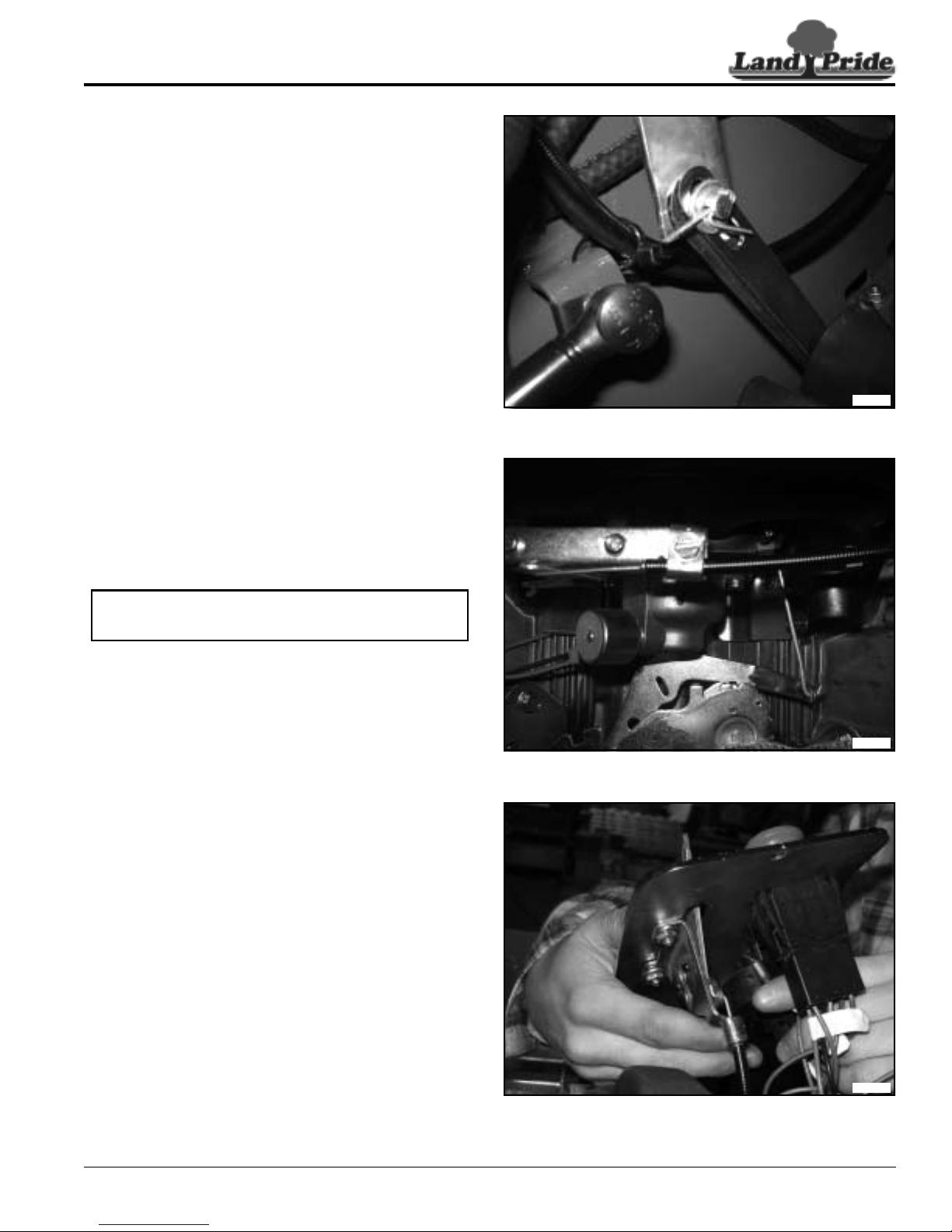
Table of Contents
Section 1: Operator Controls
Control Panel Removal
Refer to Figure 1-22:
1. Chock wheels to secure mower and prevent
movement while repairs are made.
2. Disconnect batter y to prevent accidental shock. See
“Battery Assembly Removal” on page 22.
3. Disconnect and remove seat for easy access.
4. Cut and remove plastic zip ties securing the throttle
and choke cables to the frame.
Refer to Figure 1-23:
5. Loosenengineclampsonboththethrottleand choke
cables. Mark each cable for reference.
6. Disconnect the throttle and choke cables from the
engine.
33685
Figure 1-22
NOTE: Picture is for reference only, cable
attachments will vary with engine model and type.
Refer to Figure 1-24:
7. Loosen and remove the cross head bolts on the
control panel.
8. Lift the control panel out of the fuel tank and
disconnect all electrical connections.
9. While removing the control panel, insure that the
throttle and choke cable do not become bound and
pull free of the opening in the bottom of the fuel tank.
33696
Figure 1-23
7/30/12
Figure 1-24
ZSR54 & ZSR60 Accu-Z Razor® Zero Turn Mowers 357-388SM
33697
11
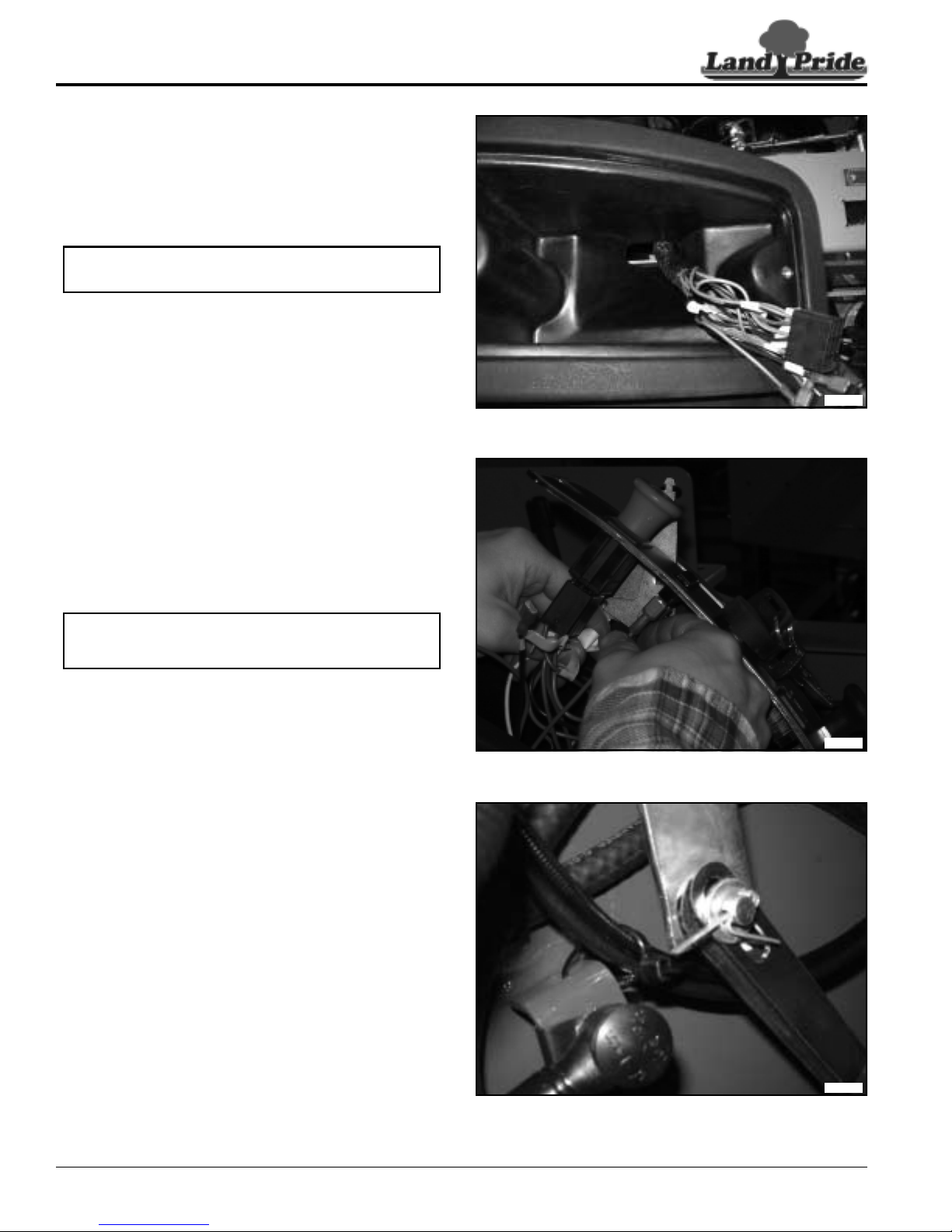
Table of Contents
Section 1: Operator Controls
Control Panel Installation
Refer to Figure 1-25:
1. Start by routing the throttle and choke cable though
the top of the fuel tank and out the opening in the
bottom of the cavity in the fuel tank.
NOTE: Mark the ends of each cable to identify
when connecting to the engine.
2. Route the throttle cable and choke cable along the
frame and between the bumper and engine, do not
connect to the engine at this time.
33698
Figure 1-25
Refer to Figure 1-26:
3. Connect the electrical connectors to the control
panel. See the “Main Harness Wiring Schematics”
on page 25 of the manual for more information on
correct connections.
NOTE: Ensure that all connectors are spaced and
firmly connected.
4. Secure control panel to the fuel tank with cross head
bolts. Tighten bolts until snug against the control
panel.
Refer to Figure 1-27:
5. Connect the throttle and choke cable to engine as
per engine specifications, see engine manual for
more information on correct engine set up.
6. Attach the throttle and choke cable to the engine
clamps allowing for enough slack to adjust correctly.
7. Secure the throttle and choke cables to the frame
withplasticziptiestopreventthecablesfrom binding
or rubbing.
8. Test cable operation for binding or dragging of
cables.
33699
Figure 1-26
ZSR54 & ZSR60 Accu-Z Razor® Zero Turn Mowers 357-388SM
12
33685
Figure 1-27
7/30/12
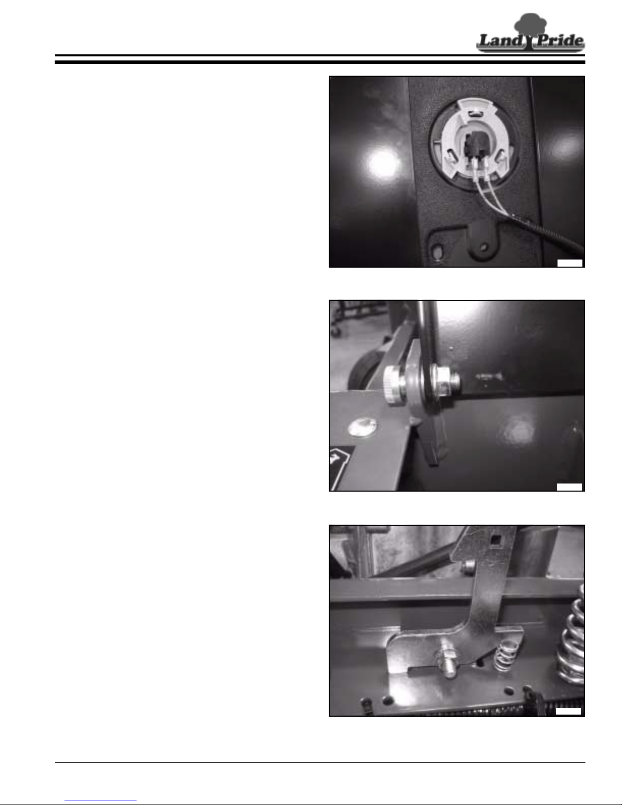
Table of Contents
Section 2: Seat & Frame
Section 2: Seat & Frame
Seat and Latch Removal
Refer to Figure 2-1:
1. Chock wheels to secure mower and prevent
movement while repairs are made.
2. Disconnect batter y to prevent accidental shock. See
“Battery Assembly Removal” on page 22.
3. Unlatch seat pan and pull the seat assembly into the
upright forward position.
4. Disconnect the operator presence switch from the
wiring harness at the switch.
Refer to Figure 2-2:
5. Loosenandremovetheseatpanretainernutsonthe
left and right side of the seat pan assembly.
6. Support the seat pan assembly and remove both
retaining hex socket bolts, remove assembly.
7. Loosen and remove four seat retaining bolts and
remove pan from seat.
33700
Figure 2-1
Refer to Figure 2-3:
8. With a long socket inserted in spring assembly,
loosen and remove the seat spring retaining nut to
remove spring.
9. Loosen and remove the latch retaining nut.
10. Holding latch return spring, remove the latch lever
from the mounting bolt.
7/30/12
Figure 2-2
Figure 2-3
ZSR54 & ZSR60 Accu-Z Razor® Zero Turn Mowers 357-388SM
33701
33702
13
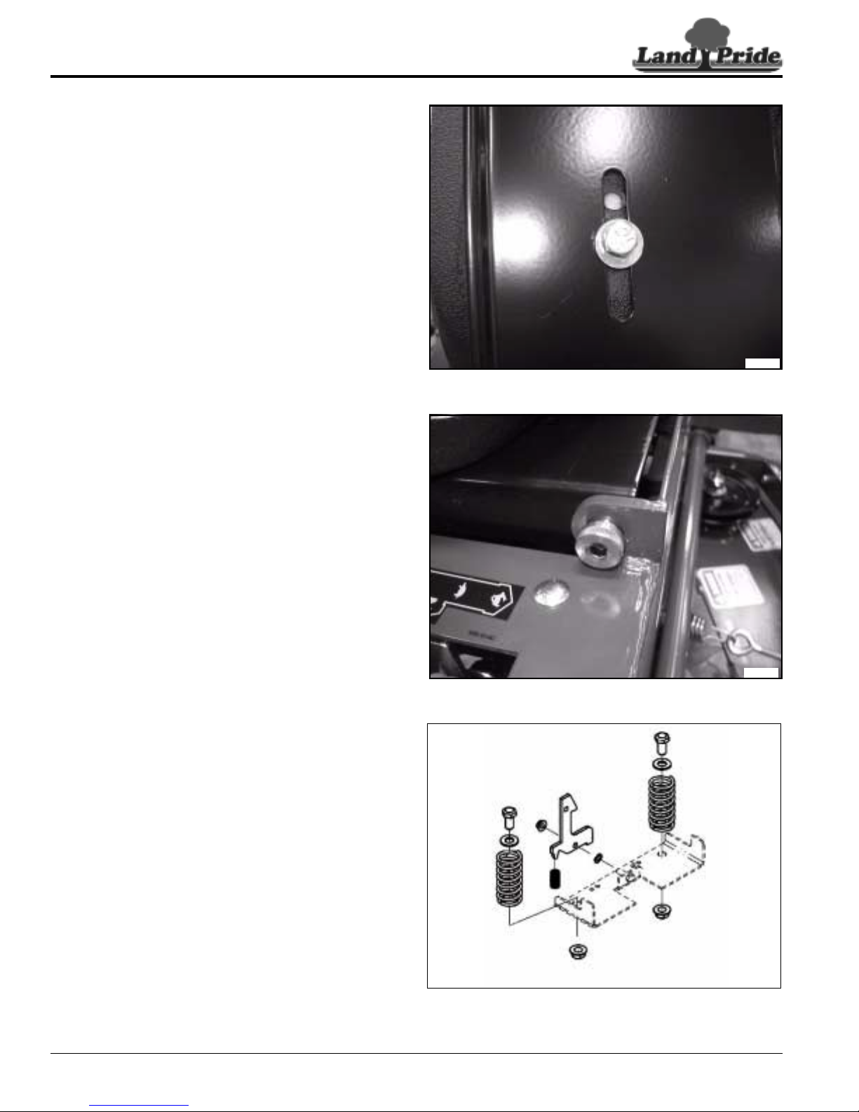
Table of Contents
Section 2: Seat & Frame
Seat and Latch Installation
Refer to Figure 2-4:
1. Align and install seat pan on seat with fourbolts,lock
washers and flat washers.
2. Center seat bolts on the seat pan slot to the middle
and tighten bolts.
Refer to Figure 2-5:
3. Align and install seat pan pivot bushings in frame
from the inside out.
4. Align and install seat pan assembly on unit with hex
socket bolts, raise and secure with flange nuts.
33703
Figure 2-4
Refer to Figure 2-6:
5. Insert washer and spr ing retaining bolt into the open
end of the seat springs.
6. Align and install the seat spring into frame and
secure with flanged lock nut.
7. Install the wavy spring washer on the seat latch
frame mount bolt.
8. Install the latch return spring onto the latch.
9. Align and install the latch on the seat latch frame bolt
while compressing the return spring.
10. Secure latch with the flanged lock nut, back nut off
1/8th of a turn.
ZSR54 & ZSR60 Accu-Z Razor® Zero Turn Mowers 357-388SM
14
33704
Figure 2-5
Figure 2-6
7/30/12

Table of Contents
Section 2: Seat & Frame
Floor Panel Removal
Refer to Figure 2-7:
1. Chock wheels to secure mower and prevent
movement while repairs are made.
2. Loosen and remove floor panel retaining bolts.
33706
Figure 2-7
Refer to Figure 2-8:
3. Pull forward on the front section of the floor panel to
disengage the slotted rear section of floor panel
mounting area.
Floor Panel Installation
Refer to Figure 2-9:
1. Align and install the slotted rear section of the floor
panel with the mower frame.
2. Align and install floor panel retaining bolts.
33707
Figure 2-8
7/30/12
Figure 2-9
ZSR54 & ZSR60 Accu-Z Razor® Zero Turn Mowers 357-388SM
33706
15

Table of Contents
Section 2: Seat & Frame
Engine Bumper Guard Removal
Refer to Figure 2-10:
1. Chock wheels to secure mower and prevent
movement while repairs are made.
2. Disconnect batter y to prevent accidental shock. See
“Battery Assembly Removal” on page 22.
NOTE: Ensure that mower is cooled before
performing any repair around the engine and
muffler to prevent accidental burning.
3. Cut and remove all plastic zip ties securing cables
and wires to the engine bumper guard.
4. Loosen and removethe locknuts from the Alan head
bolts on the lower bumper frame and remove bolts.
Refer to Figure 2-11:
5. Loosen and remove the locknuts on the engine
bumper guard bolts secured to the pedestal. Do not
remove bolts until the engine bumper guard is
removed from the unit.
6. With the lower engine bumper guard bolts removed
andthe nuts removedfrom the bolts on the pedestal,
lifttheenginebumperguardupatthefronttoremove
bolts and back to clear the engine muffler.
33708
Figure 2-10
Engine Bumper Guard Installation
Refer to Figure 2-11:.
NOTE: Never operate unit with out the rear engine
bumper guard installed to prevent accidental injury
or damage to the mower.
1. Assemble the engine bumper guard and tighten all
fasteners to standard torque. See “Torque Values
Chart” on page 79.
2. Align engine bumper guard over the muffler and
attachthefrontoftheguardtothepedestal base with
retaining bolts and lock nuts. Do not tighten until all
bolts have been installed.
Refer to Figure 2-12:
3. Insure all cables and wires are aligned inside of the
engine bumper guard and not pinched in between
the assembly and the frame.
4. Alignandinstallthelowerengine bumper guardbolts
thoughthe assembly and into the frame. Secure with
the flanged locknuts.
5. Tighten all the lower engine bumper guard bolts and
the two pedestal retaining bolts until the flanged lock
nuts are firmly secured to the main frame.
6. Withplasticziptiessecureall loose cablesandwires
to the engine bumper guard assembly.
33709
Figure 2-11
33710
Figure 2-12
ZSR54 & ZSR60 Accu-Z Razor® Zero Turn Mowers 357-388SM
16
7/30/12
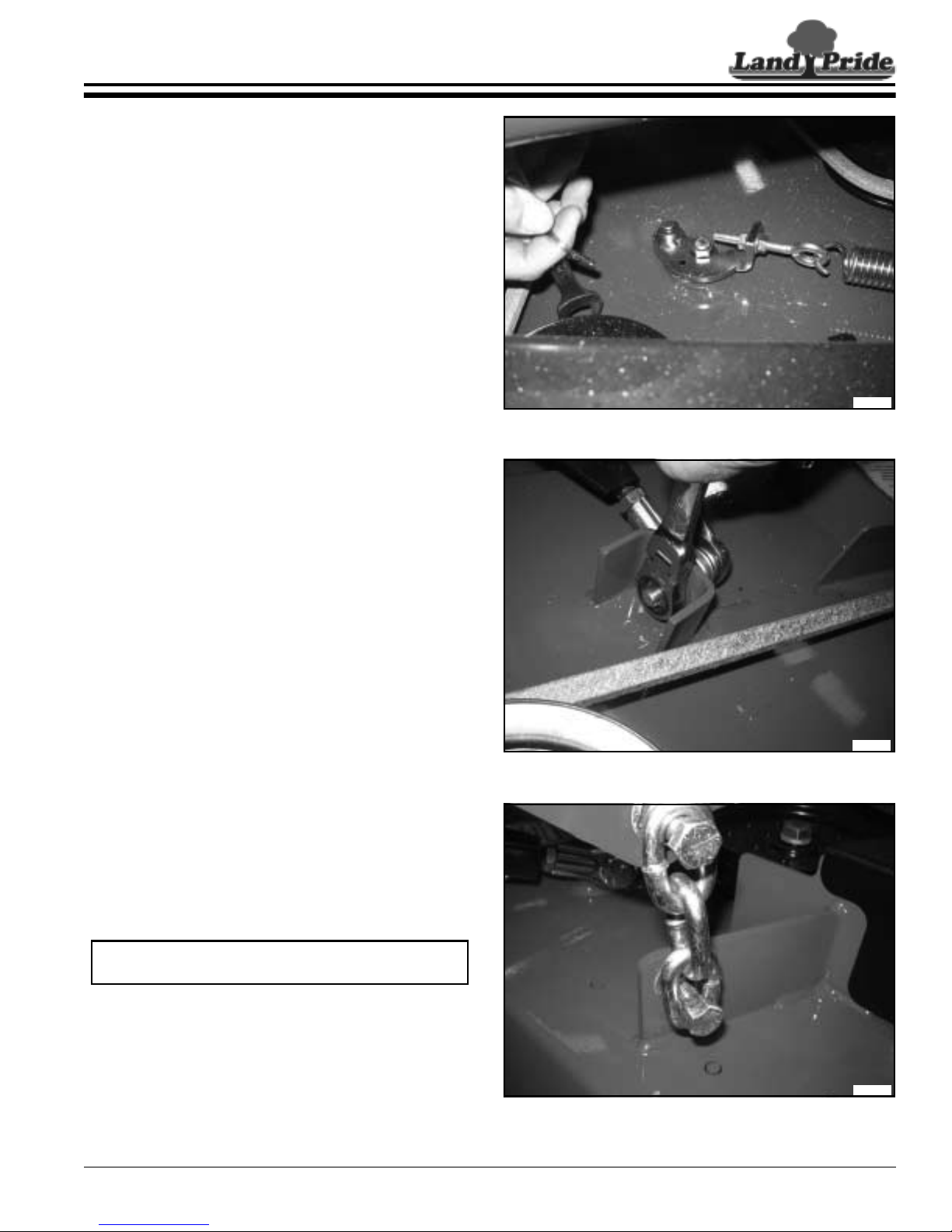
Table of Contents
Section 3: Mower Deck
Section 3: Mower Deck
Deck Removal
Refer to Figure 3-1:
1. Chock wheels to secure mower and prevent
movement while repairs are made.
2. Remove the deck height stop from the height gauge
bar.
3. Placeblocksorpalletskid under the mower deckand
lower the deck until the deck is fully supported and
the deck chains are slack.
4. Raise floor panel to access the over center latch.
Loosen deck belt tension by pulling the securing pin
onthe overcenterlatch assembly and rotate counter
clockwise to disengage the latch. Remove belt from
the clutch.
Refer to Figure 3-2:
5. Remove the seat pan assembly from the mower for
ease of access. See “Seat and Latch Removal” on
page 13.
6. Loosen the nuts on the bolts for the deck interface
gimbals and remove the bolts from the deck strut
bracket.
7. Thedeckinterfacearmsmayberemovedorsecured
to prevent them from falling onto the deck dur ing
removal of the deck.
33711
Figure 3-1
Refer to Figure 3-3:
8. Loosen and remove the flanged nuts securing the
deck lift chains to the deck lift arms. Remove the
bolts from the deck lift chains and allow the chains to
drop down onto the mower deck.
NOTE: Lift chains do not need to be removed from
the deck for these repairs.
9. Removethedeck assemblyfromunderthemowerby
pulling it out from the side.
7/30/12
Figure 3-2
Figure 3-3
ZSR54 & ZSR60 Accu-Z Razor® Zero Turn Mowers 357-388SM
33712
33690
17
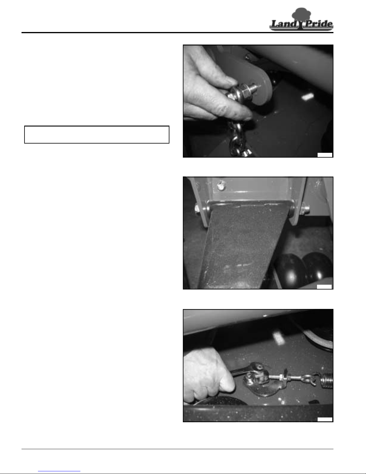
Table of Contents
Section 3: Mower Deck
Deck installation
Refer to Figure 3-4:
1. Slide the deck assembly under the mower and align
the deck so that the lift chains are under each of the
deck lift arms.
2. Raise the deck approximately 3 to 4 inches to allow
slack in the deck lift chains when installing.
3. Installthedeckliftarmchainboltsonthedeck chains
and secure with the inner flange nuts.
NOTE: Do not over tighten the chain on the bolt.
The chain should pivot easily on the bolt.
4. Attach the deck lift chains to the deck lift arms and
secure with the flanged nuts.
Refer to Figure 3-5:
5. If the deck interface arms were removedduring deck
removal, align and reinstall the deck interface arms
totheframewithpivotboltsandflangedlocknuts. Do
nottightenuntilthedeck interfacegimbalshavebeen
secured to the deck str ut bracket.
6. Align the deck interface arm gimbals to the inside of
the deck str ut bracket. Secure with bolts and
locknuts through the interface gimbals. Tighten strut
pivot bolt lock nuts.
Refer to Figure 3-6:
7. Install belt on the clutch insuring correct belt routing
as per the “Deck Drive Belt Removal &
Installation” on page 64.
8. Tighten belt by rotating the over center latch
assembly clockwise until the latch assembly
engages. Secure the over center latch with the latch
pin.
9. Remove blocks and adjust deck as per the “Deck
Adjustments” on page 50.
33713
Figure 3-4
33714
Figure 3-5
ZSR54 & ZSR60 Accu-Z Razor® Zero Turn Mowers 357-388SM
18
33715
Figure 3-6
7/30/12
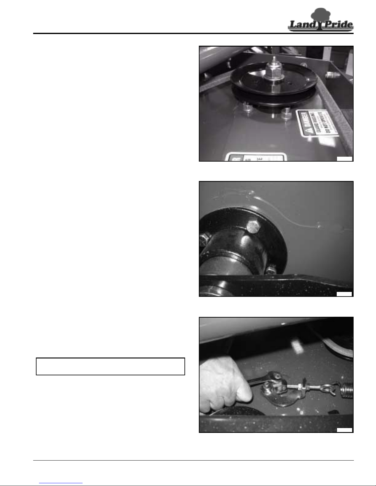
Table of Contents
Section 3: Mower Deck
Pulley and Blade Hub Removal
Refer to Figure 3-7:
1. Chock wheels to secure mower and prevent
movement while repairs are made.
2. Remove the floor panel to access the over center
latch. See “Floor Panel Removal” on page 15.
3. Loosen deck belt tension by pulling the securing pin
onthe overcenterlatch assembly and rotate counter
clockwise to disengage the latch. Remove belt from
the clutch.
4. Loosen and remove pulley retaining nut on spindle
assembly to be removed and remove pulley.
Refer to Figure 3-8:
5. Loosen and remove blade bolt from spindle
assembly to be removed and remove blade.
6. Loosen and remove the four spindle assembly
retaining nuts on top of the deck for the spindle
assembly to be removed. Pull the spindle assembly
out though the bottom of the mower deck.
33716
Figure 3-7
Pulley and Blade Hub Installation
Refer to Figure 3-9:
1. Insert spindlehubassemblythoughthebottom of the
deck and attach with bolts, lock washers, and nuts.
Tighten in a cross pattern until properly torqued.
2. Alignand install the drive pulley onto the spindle with
key and locknut. Tighten locknut to the correct
torque.
3. Install blade washer and blade onto the spindle
assembly and tighten bolt to approximately 45 ft/lbs.
NOTE: Do not over tighten blade bolt as this bolt
will tighten during operation of the mower.
4. Ensure correct belt routing per “Deck Drive Belt
Removal & Installation” on page 64.
5. Tighten belt by rotating the over center latch
assembly clockwise until the latch assembly
engages. Secure the over center latch with the latch
pin.
6. Perform belt tension adjustments as per instructions
on “Deck Drive Belt Adjustment” on page 49.
33717
Figure 3-8
33715
Figure 3-9
7/30/12
ZSR54 & ZSR60 Accu-Z Razor® Zero Turn Mowers 357-388SM
19
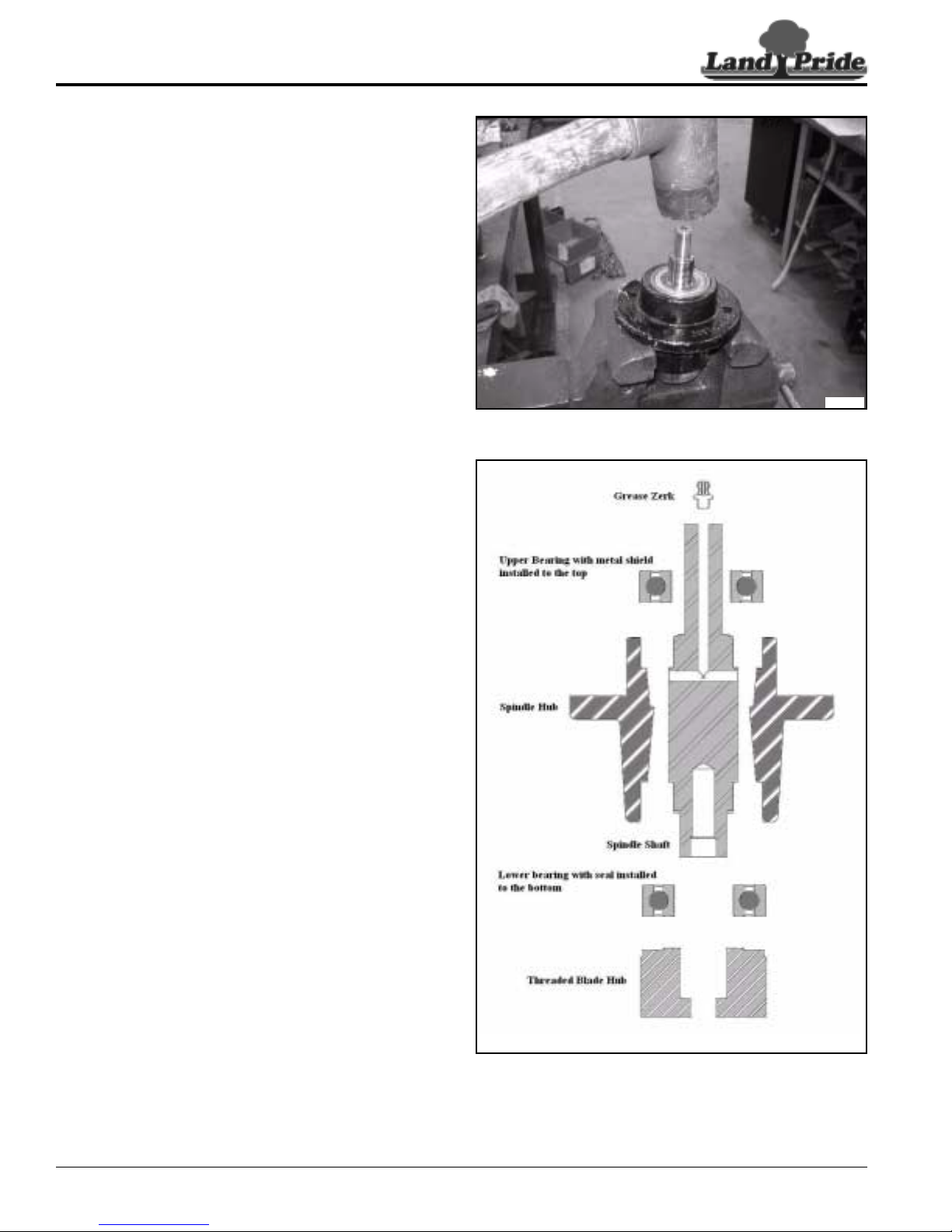
Table of Contents
Section 3: Mower Deck
Spindle Hub Rebuild
Refer to Figure 3-10:
1. Secure spindle hub assembly in vice with the lower
shaft and bearing clear of vise clamps.
2. With spindle pulley removed, loosen and removethe
grease zerk from the spindle.
3. Witharubbermallet,tapthespindle shaft to drivethe
spindle shaft, lower bearing, and blade hub from the
bottom of the spindle hub assembly.
Refer to Figure 3-11:
4. Loosenvice,turn the spindle hubassemblyoverand
re-secure in vice.
5. With a bearing removal tool or pipe, drive the upper
bearing out the top of the spindle hub.
6. Loosen vice and remove spindle hub.
7. Secure the spindle shaft with the lower bear ing and
blade hub attached in vice with the blade hub facing
upright. Pad shaft in vice with shop rag to prevent
scaring or damage to the spindle shaft.
8. Loosen and remove the blade hub from the spindle
shaft. This is a right hand thread, 1-14 class 2B
threaded shaft.
9. Remove the lower bearing from the spindle shaft. A
bearing puller may be required for removal.
10. Clean and replace spindle hub assembly parts as
needed.
11. Pre-grease or “pack” the bearing before assembly to
ensure adequate lubrication and for ease of
installation of the bearing into the spindle hub.
12. Secure the spindle shaft with the blade bolt facing
upright in vice. Pad the vice with shop rag to prevent
scaring or damage to the spindle shaft.
13. Install the bottom bearing onto the spindle shaft and
with a bearing set tool or small pipe ensure that the
bearing isfullyseatedagainstthespindleshaftlower
bearing stop.
33718
Figure 3-10
ZSR54 & ZSR60 Accu-Z Razor® Zero Turn Mowers 357-388SM
20
33719
Figure 3-11
7/30/12
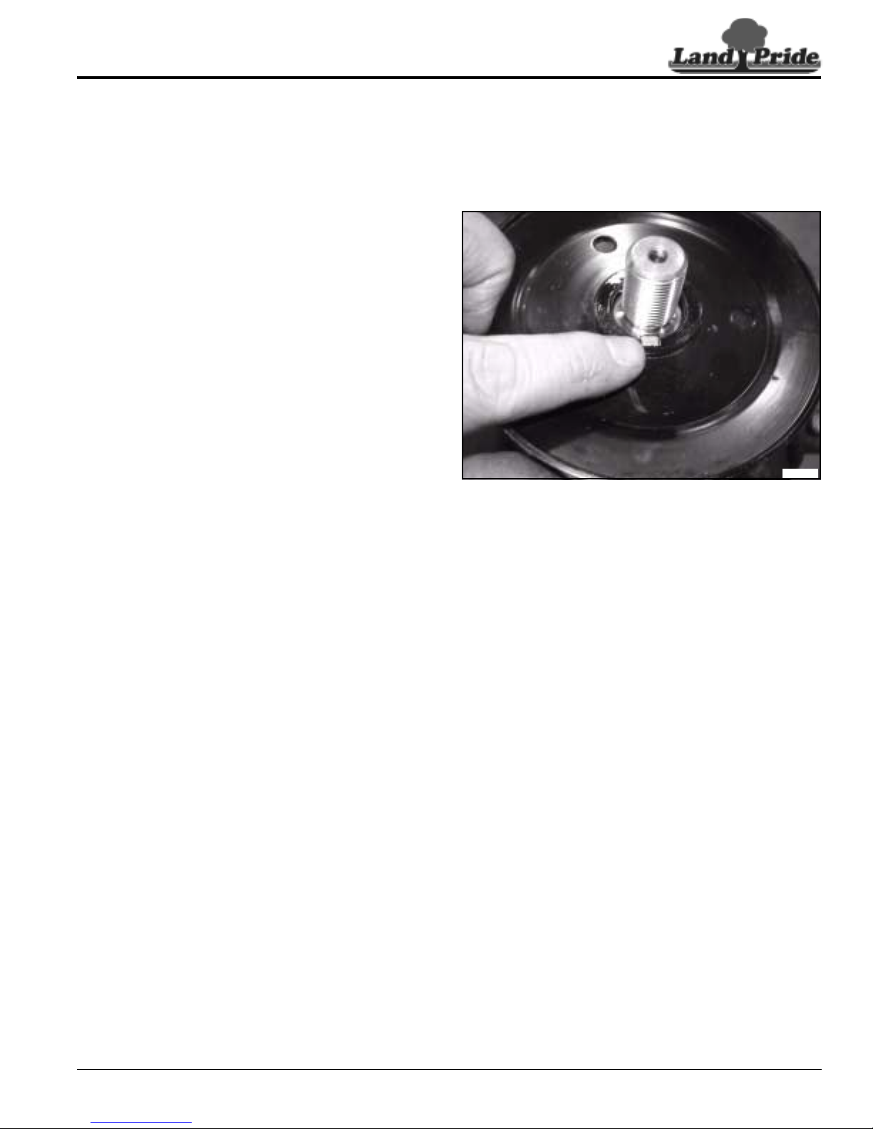
Table of Contents
Section 3: Mower Deck
Refer to Figure 3-12:
14. Thread the blade hub onto the spindle shaft. Ensure
that the stepped bearing surface is facing the lower
bearing and tighten until firmly secured against the
lower bear ing.
15. Loosen and remove the spindle shaft from the vice
and set aside on a clean surface for installation in
spindle hub. Secure the spindle hub in vice with the
top side up.
16. Apply a light coat of grease to the upper spindle
shaft. Align and install the spindle shaft assembly
though the bottom the spindle hub assembly. With a
rubber mallet, tap the blade hub to fully seat the
lower bear ing into the spindle hub.
17. Loosen vice, turn thespindle hub assembly overand
re-secure in vice with the blade hub down and
against the vise clamps to prevent lower bearing
from being driven out during installation of the top
bearing.
18. With bearing set tool or pipe, install the top bearing
overthespindleshaft.Ensurethatthemetalshieldis
installed out, away from the spindle hub assembly,
and that the bearing isfully seated in the spindle hub.
19. Install grease zerk in the top of the spindle shaft and
tighten hand tight. Attach grease gun and fill the
spindle hub assembly until grease comes out the
purge hole on the upper bearing.
20. Remove spindle hub assembly from vice. If the
spindle hub is not going to be installed in mower,
install the spindle pulley and key onto the spindle.
33720
Figure 3-12
7/30/12
ZSR54 & ZSR60 Accu-Z Razor® Zero Turn Mowers 357-388SM
21
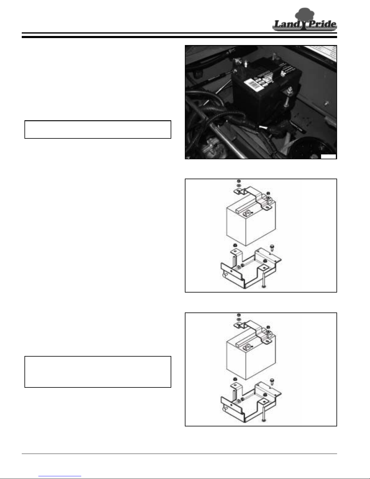
Table of Contents
Section 4: Electrical System
Section 4: Electrical System
Battery Assembly Removal
Refer to Figure 4-1:
1. Chock wheels to secure mower and prevent
movement while repairs are made.
2. For ease of access, remove the seat assembly. See
“Seat and Latch Removal” on page 13.
3. Loosen and disconnect the system battery cables
from the battery.
NOTE: Disconnect the ground cable before
removing the positive cable.
4. Loosen and remove the lock nuts on the battery hold
down bracket and remove the hold down bracket.
Refer to Figure 4-2:
5. Loosenandremovethejamnutfromthebatteryhold
down bracket bolts and remove the bolts from the
battery tray. Remove the battery from the battery
tray.
6. Loosen and remove the batter y tray retaining bolts
that connect the battery tray to unit frame.
7. Remove the batter y tray from the unit frame.
Battery Assembly Installation
Refer to Figure 4-3:
1. Align and install the battery tray in the unit frame.
2. Secure the battery tray with retaining bolts.
3. Install battery in the battery tray with terminals to the
left hand side of the unit.
4. Install the battery hold down bolts in the battery tray
and secure with flanged lock nuts.
5. Install the battery hold down strap over the battery
and secure with flanged lock nuts.
33721
Figure 4-1
33722
Figure 4-2
NOTE: Alwaysinstallthegroundsystemcableafter
the positive system cable to prevent accidental
shock or damage to the electronic components in
the mowers electrical system.
6. Attach the positive system cable to the positive
battery post.
7. 7. Attach the ground system cable to the negative
battery post. Check all wire connections and test for
system continuity.
ZSR54 & ZSR60 Accu-Z Razor® Zero Turn Mowers 357-388SM
22
33722
Figure 4-3
7/30/12

Table of Contents
Section 4: Electrical System
Wiring Harness Removal
Refer to Figure 4-4:
1. Chock wheels to secure mower and prevent
movement while repairs are made.
2. Disconnect batter y to prevent accidental shock. See
“Battery Assembly Removal” on page 22.
3. For ease of access, remove the seat assembly. See
“Seat and Latch Removal” on page 13.
4. Cut and remove all the plastic zip ties securing the
wiring harness to the frame.
Refer to Figure 4-5:
5. Remove control panel and disconnect it from wiring
harness. See ““Control Panel Removal” on page
11.
6. Disconnect the wiring harness from all brake, seat,
and neutral interlock switches.See ““Main Harness
Wiring Schematics” on page 25 for location of all
connectors.
7. Disconnecttheenginewiringharness connectorand
depress the retaining tabs on the main harness
connector and remove from mounting bracket.
8. Remove the main wiring harness from the unit.
33723
Figure 4-4
Refer to Figure 4-6:
9. Disconnect the engine wiring harness from the start
solenoid and the engine wiring. Mark each cable for
reference.
10. Remove engine wir ing harness from the unit.
NOTE: Pictures is for reference only, cable
attachments will vary with engine model and type.
7/30/12
Figure 4-5
Figure 4-6
ZSR54 & ZSR60 Accu-Z Razor® Zero Turn Mowers 357-388SM
33724
33725
23
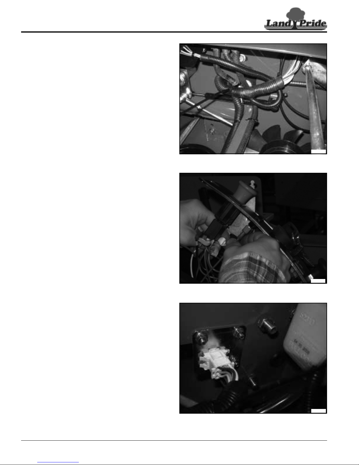
Table of Contents
Section 4: Electrical System
Wiring Harness Installation
Refer to Figure 4-7:
1. Lay out the main wiring harness and check all the
connections for good crimps and that the plastic
shielding is secured.
2. Mark all ends of the main wiring harness to ensure
proper routing. Use the “Main Harness Wiring
Schematics” on page 25 for locations of all
connections.
3. Plug the engine wiring harness connector into the
mounting bracket. Route all the branches of the
wiring harness to the appropriate areas of the
mower. Ensure that the each of the branches of the
wiring harness are routed as close to the frame and
tie down points as possible.
Refer to Figure 4-8:
4. Connect the wiring harness to the brake, seat, and
neutral interlock switches. See “Main Harness
Wiring Schematics” on page 25 for locations of all
connectors.
5. Route the control cable though the bottom of the
fender and connect all the main wiring harness
connectors to the control panel.
33726
Figure 4-7
Refer to Figure 4-9:
6. Lay out the engine wiring harness and check all the
connections for good crimps and that the plastic
shielding is secured.
7. Mark all ends of the engine wiring harness to ensure
proper routing. Use the “Engine Wiring
Schematics” on page 26 for locations of all
connections.
8. Plug the engine wiring harness in to the start
solenoid and engine wiring.
9. Plug the engine wiring harness into the main wiring
harness connector.
10. Test and secure the main and engine wiring harness
to the frame and tie down points.
ZSR54 & ZSR60 Accu-Z Razor® Zero Turn Mowers 357-388SM
24
33699
Figure 4-8
33724
Figure 4-9
7/30/12
 Loading...