

Land Pride Accu-Z Razor 357-044M, Accu-Z Razor Z44, Accu-Z Razor Z52 Operator's Manual

Table of Contents
Zero Turn Mowers
Z44 & Z52 (S/N 472620 -526170) Accu-Z Razor
®
23802
357-044M
Operator’s Manual
Read the Operator’smanualentirely. When
you see this symbol, the subsequent
!
instructions andwarnings are serious-follow
without exception. Yourlife and the lives of
others depend on it!
© Copyright 2010 Printed
Cover photo may show optional
equipment not supplied with
standard unit.
4/19/10

Table of Contents
T ab le of Contents
Important Safety Information . . . . . . . . . . .1
Safety at All Times . . . . . . . . . . . . . . . . . . . . . . . . . 1
Safety Labels . . . . . . . . . . . . . . . . . . . . . . . . . . . . . 4
Introduction . . . . . . . . . . . . . . . . . . . . . . . .7
Application . . . . . . . . . . . . . . . . . . . . . . . . . . . . . . . 7
Using This Manual . . . . . . . . . . . . . . . . . . . . . . . . .7
Owner Assistance . . . . . . . . . . . . . . . . . . . . . . . . . 7
Section 1: Assembly & Set-up . . . . . . . . .8
Uncrating Instructions . . . . . . . . . . . . . . . . . . . . . .8
Control Lever Assembly . . . . . . . . . . . . . . . . . . . . .8
Seat Assembly . . . . . . . . . . . . . . . . . . . . . . . . . . . .8
Hitch Plate Assembly . . . . . . . . . . . . . . . . . . . . . . . 8
Electrical Cable Connection . . . . . . . . . . . . . . . . . . 9
Engine Preparations . . . . . . . . . . . . . . . . . . . . . . . 9
Remove Mower From Crate Floor . . . . . . . . . . . . . 9
Section 2: Operating Procedures . . . . . .10
Mower Features . . . . . . . . . . . . . . . . . . . . . . . . . . 10
Operating Check List . . . . . . . . . . . . . . . . . . . . . . 11
Instrumentation . . . . . . . . . . . . . . . . . . . . . . . . . . 11
Engine Oil Pressure Light . . . . . . . . . . . . . . . . 11
Hour Meter . . . . . . . . . . . . . . . . . . . . . . . . . . . 11
Controls . . . . . . . . . . . . . . . . . . . . . . . . . . . . . . . . 11
Ignition Switch . . . . . . . . . . . . . . . . . . . . . . . . . 11
Throttle . . . . . . . . . . . . . . . . . . . . . . . . . . . . . . 11
Choke . . . . . . . . . . . . . . . . . . . . . . . . . . . . . . . 11
Blade Engagement Switch . . . . . . . . . . . . . . . 12
Left/Right Fuel Tank Valve . . . . . . . . . . . . . . . 12
Control Levers . . . . . . . . . . . . . . . . . . . . . . . . . 12
Park Lever . . . . . . . . . . . . . . . . . . . . . . . . . . . . 12
Deck Lift Pedal . . . . . . . . . . . . . . . . . . . . . . . . 13
Safety Start Interlock System . . . . . . . . . . . . . . . . 13
Engine Starting . . . . . . . . . . . . . . . . . . . . . . . . . .13
Driving the Mower . . . . . . . . . . . . . . . . . . . . . . . . 14
To Start and Increase Speed . . . . . . . . . . . . . 14
To Decrease Speed or Stop . . . . . . . . . . . . . . 14
Steering . . . . . . . . . . . . . . . . . . . . . . . . . . . . . 14
Moving Mower with Stalled Engine . . . . . . . . . . . 15
Safe Operating Instructions . . . . . . . . . . . . . . . . . 16
Mower Deck Operation . . . . . . . . . . . . . . . . . . . . 18
General Operating Information . . . . . . . . . . . . . . 18
Section 3: Adjustments . . . . . . . . . . . . . .19
Torque Values . . . . . . . . . . . . . . . . . . . . . . . . . . . 19
Steering Linkage . . . . . . . . . . . . . . . . . . . . . . . . . 19
Control Lever Neutral Adjustment . . . . . . . . . . 20
Steering Dampener . . . . . . . . . . . . . . . . . . . . . . . 20
Seat Adjustment . . . . . . . . . . . . . . . . . . . . . . . . . 21
Upper Control Lever Adjustments . . . . . . . . . . . . 21
Hydro-Drive Belt Adjustment . . . . . . . . . . . . . . . . 22
Deck Drive Belt Adjustment . . . . . . . . . . . . . . . . .22
Engine RPM Setting . . . . . . . . . . . . . . . . . . . . . . .22
Deck Leveling & Height Adjustment . . . . . . . . . . .22
Deck Level Adjustments . . . . . . . . . . . . . . . . .22
Deck Cutting Height Adjustment . . . . . . . . . . . . .25
Anti-Scalp Rollers . . . . . . . . . . . . . . . . . . . . . . . .25
Pivot Front Wheels . . . . . . . . . . . . . . . . . . . . . . . .25
Section 4: Maintenance & Lubrication . .26
Maintenance Locations . . . . . . . . . . . . . . . . . . . .26
Maintenance Schedule . . . . . . . . . . . . . . . . . . . . .27
Maintenance . . . . . . . . . . . . . . . . . . . . . . . . . . . .28
Torque Values . . . . . . . . . . . . . . . . . . . . . . . . . . .28
Tires . . . . . . . . . . . . . . . . . . . . . . . . . . . . . . . . . . .29
Electrical System . . . . . . . . . . . . . . . . . . . . . . . . .29
Access to IZT Units . . . . . . . . . . . . . . . . . . . . . . .30
Hydraulic System . . . . . . . . . . . . . . . . . . . . . . . . .30
Hydraulic oil and Filter . . . . . . . . . . . . . . . . . . . . .30
Fuel System . . . . . . . . . . . . . . . . . . . . . . . . . . . . .31
Fuel Filter . . . . . . . . . . . . . . . . . . . . . . . . . . . . . . .32
Draining The Fuel Tank . . . . . . . . . . . . . . . . . . . .32
Engine Oil and Oil Filter . . . . . . . . . . . . . . . . . . . .32
Oil Check, Honda Engine . . . . . . . . . . . . . . . .32
Oil Check, Briggs & Stratton Engine . . . . . . . .32
Engine Air Filter . . . . . . . . . . . . . . . . . . . . . . . . . .33
General Engine Maintenance . . . . . . . . . . . . . . . .33
Belt Replacement . . . . . . . . . . . . . . . . . . . . . . . . .33
Deck Belt Replacement Instructions . . . . . . . .33
Drive Belt Replacement Instructions . . . . . . . .34
Mower Blade Maintenance . . . . . . . . . . . . . . . . . .34
Storage . . . . . . . . . . . . . . . . . . . . . . . . . . . . . . . .36
Preparation of Engine for Storage . . . . . . . . . . . .36
New Season Preparation . . . . . . . . . . . . . . . . . . .36
Lubrication Points . . . . . . . . . . . . . . . . . . . . . . . .37
Center Blade Spindle . . . . . . . . . . . . . . . . . . . .37
Left Blade Spindle . . . . . . . . . . . . . . . . . . . . . .37
Right Blade Spindle . . . . . . . . . . . . . . . . . . . . .37
Gauge Wheel Bearing Zerk . . . . . . . . . . . . . . .38
Front Axle Center Pivot . . . . . . . . . . . . . . . . . .38
Deck Lift Pivot Points . . . . . . . . . . . . . . . . . . .38
Section 5: Specifications & Capacities . .39
Section 6: Features and Benefits . . . . . .41
Section 7: Troubleshooting . . . . . . . . . . .42
Section 8: Appendix . . . . . . . . . . . . . . . .44
Torque Values Chart . . . . . . . . . . . . . . . . . . . . . .44
Tire Inflation Chart . . . . . . . . . . . . . . . . . . . . . . . .44
Warranty . . . . . . . . . . . . . . . . . . . . . . . . . . . . . . .45
© Copyright 2010 All rightsReserved
Land Pride provides this publication “as is” without warranty of any kind, either expressed or implied. While every precaution has been taken in the preparation of this manual, Land
Pride assumes no responsibility for errors or omissions. Neither is anyliability assumed fordamages resulting from the use of theinformation contained herein. Land Pride reserves
the right to revise and improveits products as it sees fit. This publication describesthestate of this product at the time of its publication, and may not reflect the product in the future.
All other brands and product names are trademarks or registered trademarks of their respectiveholders.
Z44 & Z52 (S/N 472620 -526170) Accu-Z Razor® Zero Turn Mowers 357-044M
Land Pride is a registered trademark.
Printed in the United States of America.
4/19/10

▲
Table of Contents
Important Safety Information
Important Safety Information
These are common practices that may or may not be applicable to the products described in
this manual.
Safety at All Times
Thoroughly read and understand
the instructions given in this
manual before operation. Refer to
the “Safety Label” section, read
all instructions noted on them.
Do not allow anyone to operate
this equipment who has not fully
read and comprehended this
manual and who has not been
properly trained in the safe
operation of the equipment.
▲ Operator should be familiar with
all functions of the unit.
▲ Operate implement from the
driver’s seat only.
▲ Do not leave equipment
unattended with engine running.
▲ Dismounting from a moving
mower could cause serious injury
or death.
▲ Do not stand between the mower
and implement during hitching.
▲ Keep hands, feet, and clothing
away from power-driven parts.
▲ Wear snug fitting clothing to avoid
entanglement with moving parts.
▲ Watch out for wires, trees, etc.,
when raising implement. Make
sure all persons are clear of
working area.
▲ Turning mower too tight may
cause implement to ride up on
wheels. This could result in injury
or equipment damage.
Look For The Safety Alert Symbol
The SAFETY ALERT SYMBOL indicates there is a
potential hazard to personal safety involved and
extra safety precaution must be taken. When you
see this symbol, be alert and carefully read the
message that follows it. In addition to design and
!
configuration of equipment, hazard control and
accident prevention are dependent upon the
awareness, concern, prudence and proper training
of personnel involved in the operation, transport,
maintenance and storage of equipment.
Be Aware of
Signal Words
A Signal word designates a degree or
level of hazard seriousness. The
signal words are:
!
DANGER
Indicates an imminently hazardous
situation which, if not avoided, will
result in death or serious injury. This
signal word is limited to the most
extreme situations, typically for
machine components that, for
functional purposes, cannot be
guarded.
For Your Protection
▲ Thoroughly read and understand
the “SafetyLabel” section, read all
instructions noted on them.
!
WARNING
Indicates a potentially hazardous
situation which, if not avoided, could
result in death or serious injury, and
includes hazards that are exposed
when guards are removed. It mayalso
be used to alert against unsafe
practices.
!
CAUTION
Indicates a potentially hazardous
situation which, if not avoided, may
result in minor or moderate injury. It
may also be used to alert against
unsafe practices.
Shutdown and Storage
▲ Lower machine to ground, put
mower in park, turn off engine, and
remove the key.
▲ Detach and store implements in a
area where children normally do
not play. Secure implement by
using blocks and supports.
4/19/10
OFF
REMO
VE
Z44 & Z52 (S/N 472620 -526170) Accu-Z Razor® Zero Turn Mowers 357-044M
1

Table of Contents
Important Safety Information
These are common practices that may or may not be applicable to the products described in
this manual.
Practice Safe Maintenance
▲ Understand procedure before
doing work. Use proper tools and
equipment, refer to Operator’s
Manual for additional information.
▲ Work in a clean dry area.
▲ Put mower in park, turn off
engine, and remove key before
performing maintenance.
▲ Allow mower to cool completely
before performing maintenance..
▲ Do not grease or oil mower while
in operation.
▲ Inspect all parts. Make sure parts
are in good condition and installed
properly.
▲ Remove buildup of grease, oil or
debris.
▲ Remove all tools and unused
parts from mower before
operation.
Keep Riders
Off Machinery
▲ Riders obstruct the operator’s
view, they could be struck by
foreign objects or thrown from the
machine.
▲ Never allow children under 16
years of age to operate
equipment.
Avoid High
Pressure Fluids Hazard
▲ Escaping fluidunder pressure can
penetratethe skin causing serious
injury.
▲ Avoid the hazard by relieving
pressure before disconnecting
hydraulic lines.
▲ Use a piece of paper or
cardboard, NOT BODY PARTS, to
check for suspected leaks.
▲ Wear protective glovesand safety
glasses or goggles when working
with hydraulic systems.
▲ If an accident occurs, see a
doctor immediately. Any fluid
injected into the skin must be
surgically removed within a few
hours or gangrene may result.
Z44 & Z52 (S/N 472620 -526170) Accu-Z Razor® Zero Turn Mowers 357-044M
2
4/19/10

Table of Contents
Important Safety Information
These are common practices that may or may not be applicable to the products described in
this manual.
Prepare for Emergencies
▲ Be prepared if a fire starts.
▲ Keep a first aid kit and fire
extinguisher handy.
▲ Keep emergency numbers for
doctor, ambulance, hospital and
fire department near phone.
911
Wear
Protective Equipment
▲ Protectiveclothing and equipment
should be worn.
▲ Wear clothing and equipment
appropriate for the job. Avoid
loose fitting clothing.
▲ Prolonged exposure to loud noise
can cause hearing impairment or
hearing loss. Wear suitable
hearing protection such as
earmuffs or earplugs.
▲ Operating equipment safely
requires the full attention of the
operator. Avoid wearing radio
headphones while operating
machinery.
4/19/10
Z44 & Z52 (S/N 472620 -526170) Accu-Z Razor® Zero Turn Mowers 357-044M
3

Table of Contents
Important Safety Information
Safety Labels
Your mower comes equipped with all safety labels in place.
They were designed to help you safely operate your implement.
Read and follow their directions.
1. Keep all safety labels clean and legible.
2. Replace all damaged or missing labels. To order new
labels go to your nearest Land Pride dealer.
3. Some new equipment installed during repair requires
safety labels to be affixed to the replaced component as
specified by Land Pride. When ordering new components
make sure the correct safety labels are included in the
request.
4. Refer to this section for proper label placement.
To install new labels:
a. Clean the area the label is to be placed.
b. Spray soapy water on the surface where the label is to
be placed.
c. Peel backing from label. Press firmly onto the surface.
d. Squeeze out air bubbles with the edge of a credit card.
23732
23621
838-303C
Danger: Battery
(In Engine Compartment Beneath The Seat Mount)
838-815C
Warning: Rollover Hazard
Z44 & Z52 (S/N 472620 -526170) Accu-Z Razor® Zero Turn Mowers 357-044M
4
23619
838-306C
Warning: Do not operator without deflector
4/19/10

Important Safety Information
Table of Contents
23620
23619
838-307C
Warning: Moving Parts
838-308C
Warning: Rotating Blade Hazard
4/19/10
838-833C
23620
Z44 & Z52 (S/N 472620 -526170) Accu-Z Razor® Zero Turn Mowers 357-044M
Warning: Fuel (Imbedded in Fuel Tank)
5

Important Safety Information
Table of Contents
838-444C
23643
Danger: Muffler Hot
(Both Sides of Engine)
23620
23643
Z44 & Z52 (S/N 472620 -526170) Accu-Z Razor® Zero Turn Mowers 357-044M
6
838-310C
Warning: General
818-543C
Danger: Guard Missing
4/19/10

Introduction
Table of Contents
Introduction
Land Pride welcomes you to the growing family of new
product owners.
This mower has been designed with care and built by
skilledworkers using quality materials.Properassembly,
maintenance and safe operating practices will help you
get years of satisfactory use from the machine.
Application
The Accu-Z®Razor Mowers from Land Pride are
compact in size and ideal for homeowner grass
maintenance. The Razor is a true zero-turn mower:
When mowing alongside a building or landscaping, the
Razor allows you to turn away and not hit anything with
the rear end. Also, the control lever heights are
adjustablemaking the mowercomfortabletohandle. See
“Section 5: Specifications & Capacities” on page 39
and “Section 6: Features and Benefits” on page 41 for
additional information and performance enhancing
options.
Using This Manual
•
This Operator’s Manual is designed to help familiarize
you with safety, assembly, operation, adjustments,
troubleshooting, and maintenance. Read this manual
and follow the recommendations to help ensure safe
and efficient operation.
• The information contained within this manual was
current at the time of printing. Some parts may change
slightly to assure you of the best performance.
• To order a new Operator’s or Parts Manual contact
your authorized dealer. Manuals can also be
downloaded, free-of-charge from our website at
www.landpride.com or printed from the Land Pride
Service & Support Center by your dealer.
Terminology
“Right” or “Left” as used in this manual is determined by
facing forward while sitting in the operator seat unless
otherwise stated.
Definitions
NOTE: A special point of information that the
operator must be aware of before continuing.
IMPORTANT: A special point of information related
to its preceding topic. Land Pride’s intention is that
this information should be read and noted before
continuing.
Owner Assistance
The Warranty Registration card should be filled out by
the dealer at the time of purchase. This information is
necessary to provide you with quality customer service.
If customer service or repair parts are required contact a
LandPridedealer.Adealer has trained personnel, repair
parts and equipment needed to service the mower.
The parts on your mower have been specially designed
and should only be replaced with genuine Land Pride
parts. Therefore, should your mower require
replacement parts go to your Land Pride Dealer.
For parts and service to yourmower engine, contact
your nearest engine dealer or call Customer Service
Hotline provided below.
Service Manual: Honda 18 HP - P/N GXV610K1
Honda 20 HP - P/N GXV620K1
B&S 20 HP - 273521-5/99
B&S 25 HP - 273521-5/99
Owner’s Manual: Honda 18 HP - P/N 31ZJ4620
Honda 20 HP - P/N 31ZJ4620
B&S 20 HP - 276245-5/05
B&S 25 HP - 276245-5/05
Honda Service Hotline: 1-770-497-6400
B&S Service Hotline: 1-800-999-9333
Serial Number Plate
For prompt service always use the serial number and
modelnumber when ordering parts from your Land Pride
dealer.Besure to include your serialandmodelnumbers
incorrespondencealso.RefertoFigure1forthelocation
of your serial number plate.
23620
Serial Number Plate Location
Figure 1
Further Assistance
Your dealer wants you to be satisfied with your new
mower. If for any reason you do not understand any part
of this manual or are not satisfied with the service
received, the following actions are suggested:
1. Discuss the matter with your dealership service
manager making sure he is aware of any problems
youmayhaveand that he has had the opportunityto
assist you.
2. If you are still not satisfied, seek out the owner or
general manager of the dealership, explain the
problem and request assistance.
3. For further assistance write to:
Land Pride Service Department
1525 East North Street
P.O. Box 5060
Salina, Ks. 67402-5060
E-mail address
lpservicedept@landpride.com
4/19/10
Z44 & Z52 (S/N 472620 -526170) Accu-Z Razor® Zero Turn Mowers 357-044M
7
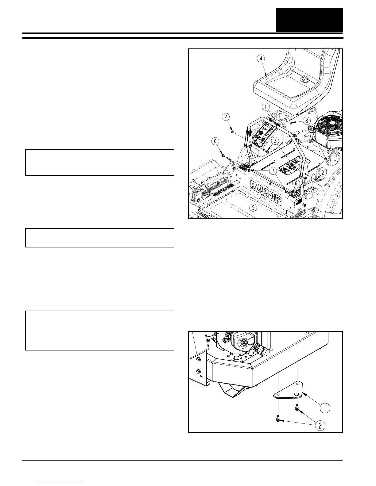
Table of Contents
Section 1: Assembly & Set-up
Section 1: Assembly & Set-up
Uncrating Instructions
Thecrate is assembled with wire clips. The mowerframe
is banded to the crate floor.
1. First remove the top panel by prying the wire clips
free with a pry bar. Then remove the side panels in
the same way.
2. Cut metal bands securing front wheels to the crate
floor. Discard bands.
Control Lever Assembly
Refer to Figure 1-1:
Control levers (#1) are factory shipped rotated down and
secured with plastic ties.
IMPORTANT: Be careful not to cut the seat cover
when removing packing material around the seat.
Cutting the seat cover will void its warranty.
1. Being careful not cut control lever handles, cut
plastic ties securing the control levers (#1).
2. Rotatecontrol levers(#1) up until theboltholesalign.
Install bolts (#3) and nuts (#2) as shown.
3. Align control leverhandles with each other and
tighten nuts (#2).
NOTE: See "Upper Control Lever Adjustments" on
page 21 for final adjustments to the control levers.
Seat Assembly
Refer to Figure 1-1:
1. The seat (#4) is factory mounted to the hinged seat
platform (#5). Cut plastic ties securing the seat
platform to the crate frame.
2. Spread control levers(#1) fully apart before
attaching the seat platform (#5) to the mower frame.
IMPORTANT: The ar m rests on the Deluxe Seat
must be pivoted up when attaching the seat
platform to the mower deck. Leaving arm rests
down while attaching the seat platform can cut
the arm rest covers and void the warranty.
23623
Control Lever & Seat Assembly
(Standard Seat Assembly Shown)
Figure 1-1
Hitch Plate Assembly
Refer to Figure 1-2:
A hitch plate (#1) is supplied with the mower and is
shipped packaged with the manual.
1. Remove two 5/16"-18 x 5/8" GR5 hex flange
screws (#2) located under the bumper.
2. Install hitch plate (#1) as shown with existing
5/16"-18 x 5/8" GR5 hex head flange screws.
3. Tighten 5/16" hex head flange screws (#2) to 17 ft.
lbs. of torque.
3. Pivot the ar m rest on the Deluxe Seat up.
4. Mountseatplatform to the hinge tabs at the frontwith
two 5/16”-18 x 5/8” lg. GR5 bolts (#6) and two
5/16”flangehex locknuts(#7).Tighten nuts snugly to
remove all play and then back nuts up one-quarter
turn.
5. Connect switch wires on the mower to the seat
switch located under the seat.
6. Hinge the seat platform down and secure in place
with two 5/16"-18 x 3/4" lg. phillips head machine
screws (#8).
7. The seat platform is slotted so the seat can be
adjusted to fit the operator. See "Seat Adjustment"
on page 21 for positioning.
Z44 & Z52 (S/N 472620 -526170) Accu-Z Razor® Zero Turn Mowers 357-044M
8
23624
Hitch Plate Assembly
Figure 1-2
4/19/10

Section 1: Assembly & Set-up
Table of Contents
IMPORTANT: Do not pull a trailer or implement
exceeding 300 pounds towing capacity and 50
pounds tongue weight. Loss of control may result.
Do not make turns that will cause a trailer or
implement being towed with the hitch to come in
contact with the mower or damage may result.
Electrical Cable Connection
Refer to Figure 1-3:
!
Incorrect battery cable connections can damage mower’s
electrical system and cause battery cables to spark. Sparks
around a battery can result in a battery gas explosion and
personal injury.
Keep battery terminals from touching any metal mower parts
when removing or installing the battery. Do not allow metal
tools to short between the battery terminals and metal mower
parts. Shorts caused by battery terminals or metal tools
touching metal mower components can cause sparks. Sparks
can cause a battery gas explosionwhich will resultin personal
injury.
WARNING
• Always disconnect negative (black) battery cable before
disconnecting positive (red) cable.
• Always reconnect positive (red) battery cable to the
positive(+) post beforereconnectingnegative(black)cable
to the negative (-) post.
!
WARNING
BlackNegative
Battery Cable
Connect the black negative battery cable to the battery’s
negative post with 1/4"-20 x 3/4" GR5 hex head serrated
screw, flat washer, lock washer and nut before starting
the mower. Tighten hex nut to 8 ft. lbs. of torque.
Engine Preparations
1. Check engine oil level at the dipstick. Add oil if oil is
below the full mark on the dipstick. Do not overfill.
Refertoenginemanual for oil recommendation. Also
see"EngineOilandOil Filter" instructionson page 32.
NOTE: Vehicles are shipped from the factorywith
about a quart of fuel in the tank
2. See "Fuel System" instructions on page 31 before
adding fuel. Add fuel to the fuel tank.
.
Remove Mower From Crate Floor
IMPORTANT: Thoroughly read and understand
"Section 2: Operating Procedures", pages 10 to 18
before starting and moving the mower.
1. Make a ramp in front and levelwith the crate floor to
be used for driving the mower off.
2. Checkunder the mowertomakesure it is not banded
to the crate floor. Remove any bands that are still
present.
3. Follow all precautions and operating information
provided in "Section 2: Operating Procedures"
before starting and driving the mower off.
4. Raise deck fully up.
5. Start the engine and drive the mower forward off the
crate floor.
6. Make necessary adjustments to the mower as
outlined in "Section 3: Adjustments" beginning on
page 19.
Negative
Post
Connecting the Negative Cable
Figure 1-3
IMPORTANT: The negative battery cable is
disconnected before leaving thefactory and is tobe
disconnected after initial dealer set-up to prevent
battery discharge while setting on the dealer lot.
4/19/10
Z44 & Z52 (S/N 472620 -526170) Accu-Z Razor® Zero Turn Mowers 357-044M
9

Table of Contents
Section 2: Operating Procedures
Section 2: Operating Procedures
Mower Features
Refer to Figure 2-1
YourRazorridingmowerisdesignedwithinnovativeand
state-of -the art features. Knowing the location and how
thesefeaturesworkwill make handling your mower more
comfortable. Below is a list of the major features we will
be reviewing in this section.
12
18
22
7
6
5
8
13
14
17
9
22
21
Muffler Shield
Is Located Under
the Engine
18
19
20
1. Blade Engagement Switch
2. Oil Pressure Light
3. Ignition Switch
4. Hour Meter
5. Throttle Lever
6. Choke Lever
7. Battery (Located under the seat)
8. Control Levers
12
3
4
9. Deck Height Indicator
10. Discharge Chute (Guard)
11. Right Deck Cover (Guard)
12. Left Deck Cover (Guard)
13. Anti-Scalp Wheels
14. Deck Adjusting Rod
15. Floor Platform (Guard)
16. Deck Lift Pedal
Razor Features
Figure 2-1
14
15
13
11
8
10
17. Park Lever
18. Fuel Tanks
19. Left/Right Fuel Tank Valve
20. Seat Platform (Guard)
21. Muffler Shield (Guard)
22. Bypass Valve Rods
16
23643
Z44 & Z52 (S/N 472620 -526170) Accu-Z Razor® Zero Turn Mowers 357-044M
10
4/19/10
Section 2: Operating Procedures
Table of Contents
Operating Check List
Hazard control and accident prevention are dependent
upon awareness, concern, prudenceand proper training
involved in operation, transport, maintenance and
storage of the riding mower. Therefore, it is absolutely
essential that no one operates the mower without first
havingread,fully understood and become totally familiar
with the Operator’s Manual. Make sure the operator has
paid particular attention to:
• Important Safety Information, pgs. 1 to 6
• Section 1: Assembly & Set-up, pg. 8
• Section 2: Operating Procedures, pgs. 10 to 18
• Section 3: Adjustments, pgs. 19 to 25
• Section 4: Maintenance& Lubrication,pgs. 26 to 38
Before beginning to operate your mower the following
Operating Checklist should be performed:
Operating Checklist
✔ Check Reference
Read “Important Safety Information”
Read “Operating Procedures”
Lubricate mower as needed. Refer toLubrication.
Check mower safety start interlock system daily
prior to operation.
Check mower initially and periodically for loose
bolts & pins, Torque V alues Chart.
Make sure all guards and shields are in place.
Page 1
Page 10
Page 37
Page 13
Page 44
Page 10
IMPORTANT: Prevent damage to the deluxe seat
arm rests when hinging the seat platform. Before
hinging the seat platform up, spread the control
leversfully apart,set the par k lever to (ON) and pivot
the seat arm rests up.
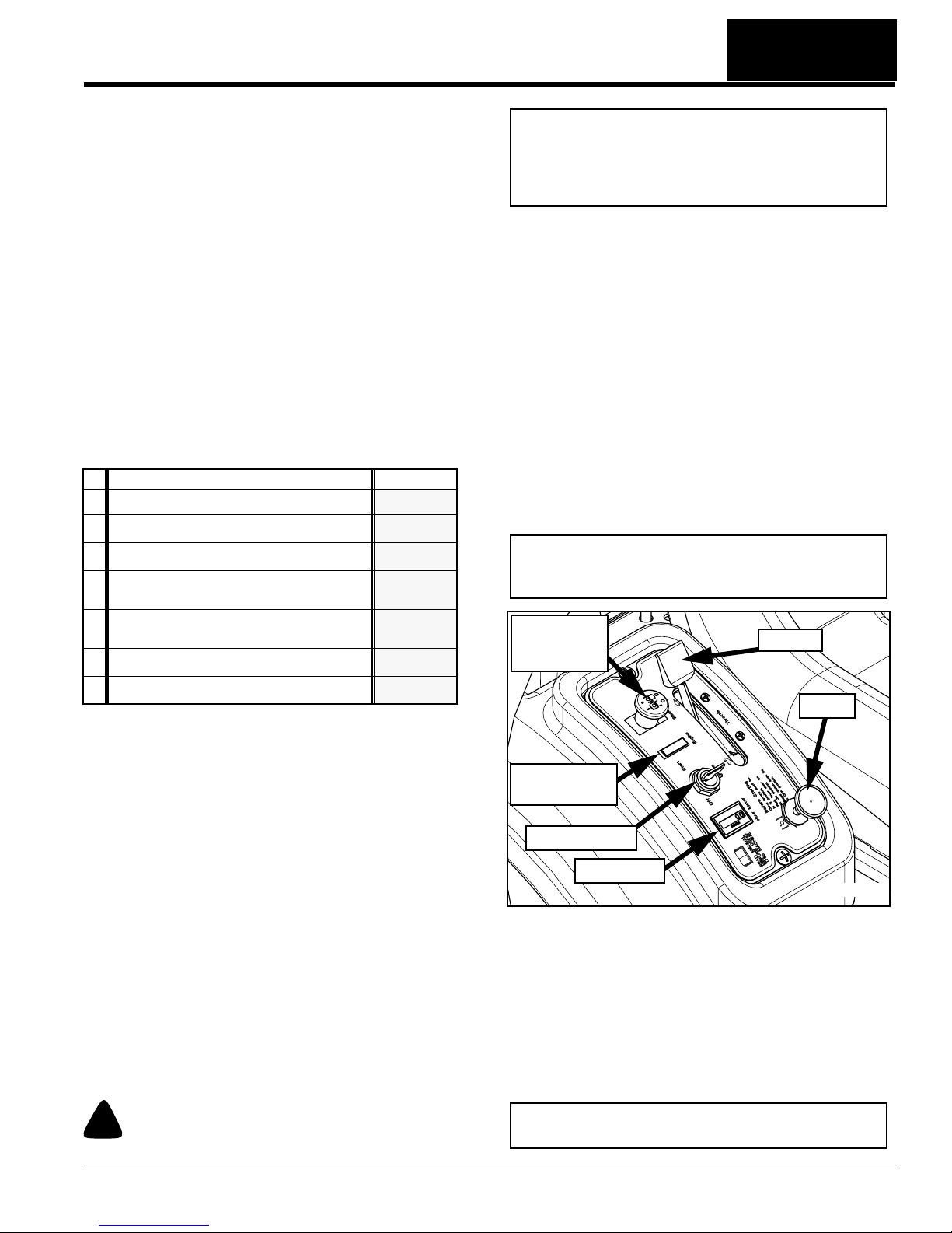
Ignition Switch
Refer to Figure 2-2:
A three position ignition switch: off, run, and start is
provided.Withkey inserted, rotate it clockwise toSTART
position; release key when engine starts, and switch will
automatically return to RUN position. Turn key
counterclockwise to OFF position to stop engine.
Throttle
Refer to Figure 2-2:
A cable is linked from engine to throttle for controlling
engine speed. Move throttle lever forward to increase
enginerpmand rearward to decrease rpm. Always travel
and cut grass with throttle set at full engine rpm speed.
Slow down travel speed by pulling back on the control
levers. Slow engine rpm speed only if mower is not
traveling or powering the cutting blades.
IMPORTANT: Always operate throttle at full engine
rpm while traveling or cutting grass. Slow engine
rpm may overheat engine and hydraulic Pumps.
Blade
Engagement
Switch
Throttle
Check blade for nic ks and sharpness.
Page 34
Instrumentation
Engine Oil Pressure Light
Refer to to Figure 2-2:
This light comes on when ignition switch is placed in
RUN position and stays lit until theengineis running with
a safe oil pressure. Shut engine off immediately if light
comes on during operation. Locate and correct the
problem.
Hour Meter
Refer to Figure 2-2:
Registers 1/10 hour increments up to 9,999.9 total hours.
The meter is connected to the ignition switch and records
accumulative time only while the engine is running. See
“Maintenance Schedule” on page 27.
Controls
For general location of the controls described in this
section, refer to Figure 2-1 on page 10 andFigure 2-2 on
page 11.
!
Do not operate mower while smoking!
WARNING
Choke
Engine Oil
Pressure Light
Ignition Switch
Hour Meter
23686
Control Panel
Figure 2-2
Choke
Refer to Figure 2-2:
A cable is linked from engine to choke knob to choke the
engine during starting. When choke control knob is
down, the choke is off (engine running position). When
controlknob is pulled up, the choke is on (engine starting
position). Shut choke off soon after engine has started.
IMPORTANT: DO N OT operate mower with choke
pulled up or on. (engine starting position).
4/19/10
Z44 & Z52 (S/N 472620 -526170) Accu-Z Razor® Zero Turn Mowers 357-044M
11
Section 2: Operating Procedures
Table of Contents
Blade Engagement Switch
Refer to Figure 2-2:
TheBladeengagementswitchengagesthedeck blades.
Pullswitchup to engage blades and push switch down to
disengage the blades.
IMPORTANT: Never engage blades with engine
running at high rpm or when the deck is under load.
Clutch, belts or deck could be damaged.
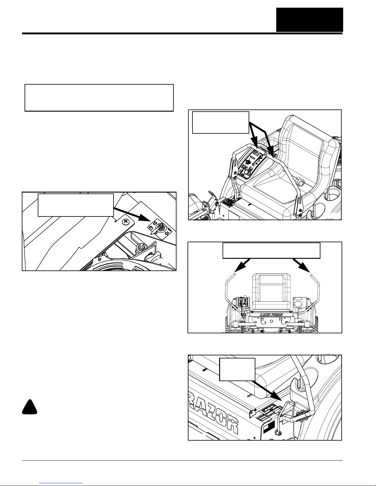
Left/Right Fuel Tank Valve
Refer to Figure 2-3:
Located behind the seat on one side is the Left/Right
Fuel Tank Valve for controlling which fuel tank is in use.
The valve lever must be over one of the two arrows to
supply fuel to the engine. Arrows point to the fuel tank
beingused.Switch valve from one tank to the other when
tankin use is about out of fuel. The mowerdoesnothave
tobeturned off to make the switch. See“FuelSystem”on
page 31 for more information.
Left/Right Fuel Tank Valve
Center Position “O”
as Shown is OFF
park lever to (ON). The control levers will be locked in
place and cannot be accidently bumped or pulled into
power until the park lever is returned to the (OFF)
position. Always set park to (ON) before getting off the
mower and always leave the park lever in the (ON)
position until seated and ready to start traveling.
In the event of a system failure while mowing, turn the
switch key off, move the control levers out and engage
the park lever to (ON) to stop or slow the mower.
Control Levers With
Handles Placed In
Operating Position
23620
23688
Left/Right Fuel Tank Valve
Figure 2-3
Control Levers
Refer to Figure 2-4 and Figure 2-5:
The control levers are used to steer, accelerate, brake
and change direction. Pulling the lever handles together
and pushing forward from neutral position will move the
mower forward. Pushing one lever more than the other
will turn the mower. Pulling back on the levers from the
neutral position will move the mower in reverse and
pulling one lever back further than the other will turn the
mower. Use levers for braking by returning them to
neutral. See “Driving the Mower” on page 14 for a
detailed description of operating the control levers.
Park Lever
Refer to Figure 2-5 and Figure 2-6:
Control Levers
Figure 2-4
.
Control Levers Must Be Spread
Fully Apart Before Park Can Be Set
23625
Control Levers Spread Fully Apart
Figure 2-5
Park Lever
Pulled Up
(Set To ON)
!
WARNING
The park lever is not designed to hold the mower on steep
slopes.
Both rear wheels are set in park when the park lever is
engaged. To place the mower in park, set control levers
in neutral, spread control levers fully apart and set the
Z44 & Z52 (S/N 472620 -526170) Accu-Z Razor® Zero Turn Mowers 357-044M
12
23684
Park Lever Set To (ON)
Figure 2-6
4/19/10

Section 2: Operating Procedures
Table of Contents
Deck Lift Pedal
Refer to Figure 2-7:
The deck lift pedal is used to raise and lower the deck
and to set deck cutting height.
1. Pushing on the deck lift pedal with your foot will raise
the deck.
2. Using the deck height indicator, place deck height
locking pin into the desired cutting height hole.
3. Lower deck gently against locking pin.
Whengoing over obstructions, push the deckliftpedal to
raise the deck. Go around the obstruction if the deck will
not raise high enough. Never mow over obstructions
you are not certain the deck will clear.
.
DeckHeight
Locking Pin
Deck Lift
Pedal
8. Set the park lever to (OFF) and slowly raise off the
seat. The engine should stop within five seconds.
9. With the control levers spread fully apart and the
park lever set to (ON), restart the engine.
10. With the park lever set to (ON) and the engine
running at a slow idle, pull up on the blade
engagement switch to turn the blades (ON). Slowly
raise off of the seat. The engine should stop within
five seconds.
11. Replace the seat safety switch if the switch failed to
operate properly in any of the above steps and if no
other cause such as damaged wir ing can be
determined.
12. Contact your local Land Pr ide Dealer if the problem
cannot be located.
Engine Starting
The Razor safety start interlock system is also designed
to protect the operator and others from accidental injury
due to unintentional engine starting. The engine starting
motor will not engage until:
• Park lever is in the up position (ON).
• Blade engagement switch is in the down position
(OFF).
DeckHeight
Indicator
23621
Deck Lift Pedal
Figure 2-7
Safety Start Interlock System
The mower is equipped with a safety start interlock
system consisting of park switch, seat switch and blade
engagement switch. Check mower safety start interlock
system daily, prior to operation. This system is an
important mower safety feature. It should be repaired
immediatelyif it malfunctions. The machine incorporates
a separate seat switch which will stop the mower engine
when the operator is unseated for any reason while the
mower is moving or the blades are engaged. This is a
safetyfeaturedesigned to prevent runaway or accidental
entanglement. To inspect the system:
4. The operator must be on the seat when testing the
seat safety switch.
5. Spread control leversfully apart and set the park
lever to (ON).
6. Start mower engine per the instructions outlined in
sectionon Engine Star ting below.Allowtheengineto
warm up to operating temperature.
7. With the blade engagement switch down (OFF), and
park lever set to (ON), slowly raise off of the seat.
The engine should continue to run.
!
WARNING
Never leave the machine unattended with key in ignition
switch.
NOTE: The operator’s seat is equipped with a
separate safety switch. The engine will stop if forany
reason the operator should become unseated when
the park lever is (OFF) or the blade engagement
switch is (ON).
The following steps are the correct procedures for
starting the engine. If difficulty is encountered, contact
the Land Pride Dealer in your area.
1. Perform daily pre-operation checks before starting
the mower. (See “Operating Check List” on page
11.)
2. Makesure the control leversare in the park position,
park lever is (ON) and blade engagement switch is
disengaged (OFF).
3. Set throttle at approximately 1/2 open position.
NOTE: Use choke when engine is cold or if warm
engine fails to start within 5 seconds of cranking.
Avoid flooding. Operate the engine without choking
as soon as possible.
4. Insert key in ignition switch and rotate clockwise to
engage starting motor. Release key when engine
starts.
4/19/10
Z44 & Z52 (S/N 472620 -526170) Accu-Z Razor® Zero Turn Mowers 357-044M
13
 Loading...