

Page 1
Front Roller Option
Assembl y Instructions
Use with 15 Series 48" & 72" Overseeder
Before You Start
When you see this symbol, the subsequent
instructions and warnings are serious - follow
!
without exception. Your life and the lives of
others depend on it!
IMPORTANT: Before you begin, read these
instructions and check to be sure all parts and tools
are accounted for. Please retain these installation
instructions for future reference and parts ordering
information.
These optional assembly instructions contain only
information on assembling the attachment to the main
unit. Please read these installation instructions and the
vehicle Operator’s Manual thoroughly before beginning.
Especially read information relating to safety concerns.
Also included in the Operator’s Manual is important
information on operation, adjustment, troubleshooting,
and maintenance for this attachment (some manual
sections do not apply to all accessories).
A separate Parts Manual for replacement parts can be
purchasedfromyourdealer oravailable freeof chargeat
www.landpride.com. Have model and serial numbers
handy when placing an order.
Manual No. 308-305M
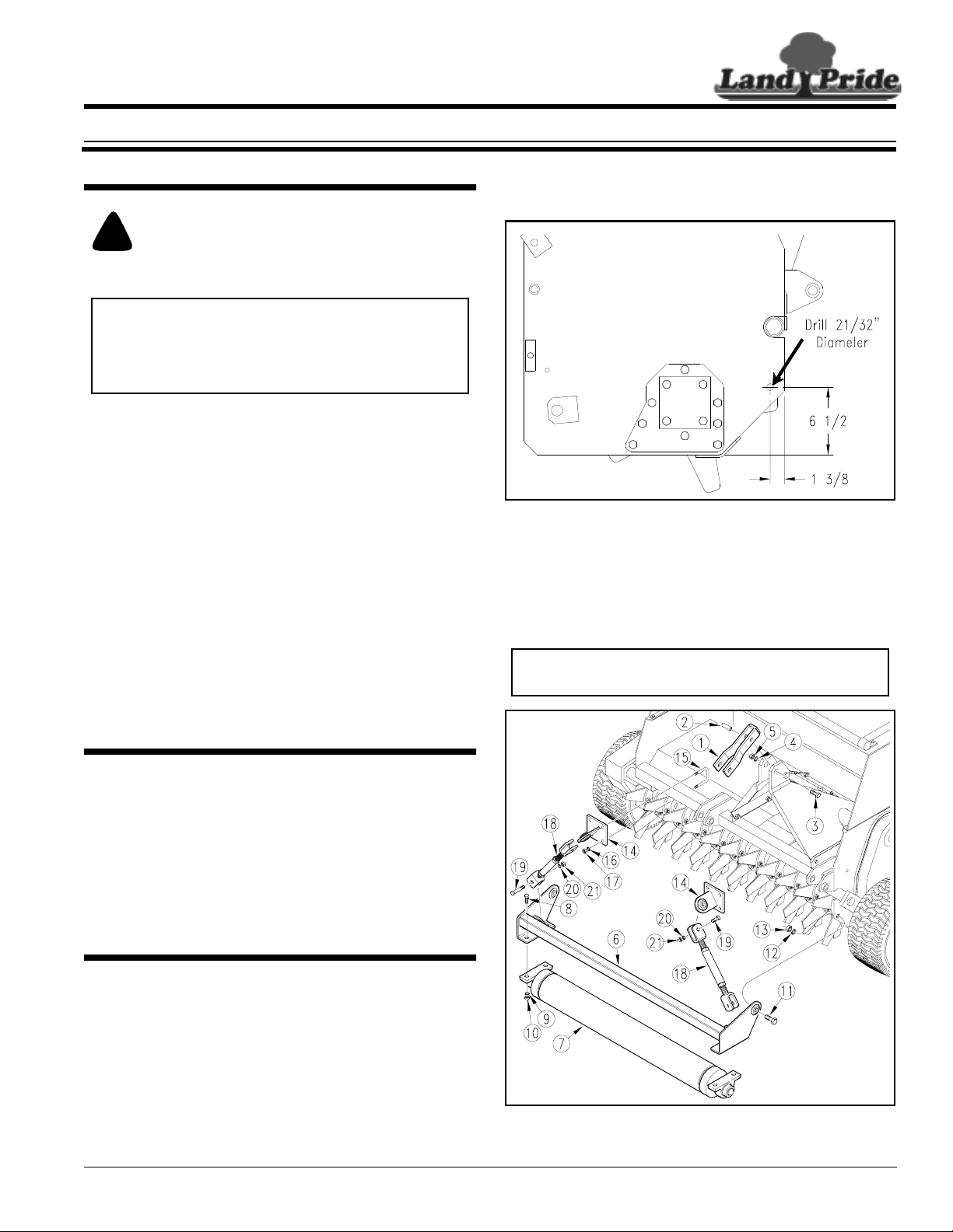
Attach that assembly to your overseeder using 5/8" x 2"
long bolts (#11), 5/8" lock washers (#12) and 5/8" hex
nut (#13).
14801
Hole Locations Typical on Both Ends of Seeder
Figure 1
Use the1/2" x 2 1/2" x 3 1/2"long u-bolts (#15), 1/2"lock
washers (#16) and 1/2" hex nuts (#17) to attach the
turnbuckle mounts (#14). The turnbuckle (#18) should
then be attached with 5/8" x 2 1/2" long bolts (#19), 5/8"
lock washers (#20) and 5/8" hex nuts (#21).
Manual Part Numbers:
• Operator’sManual . . . . . . . . . . . . . . . . . 308-303M
• Parts Manual . . . . . . . . . . . . . . . . . . . . . 308-303P
General Information
These option assembly instructions apply to the Front
Roller Packages listed below:
308-258A OS1548 Front Roller Assembly
308-259A OS1572 Front Roller Assembly
Starting on page 3 is a detailed listing of parts included
in these kits. Usethis listas a checklistto inventoryparts
received.
Assembly Instructions
Installation Instructions
Refer to Figure 1 for front roller mounting hole locations.
Refer to Figure 2:
Attach the floating top link (#1) to the overseeder hitch
using the spacer tube (#2), a 3/4" x 4" long bolt (#3),
3/4" lock washer (#4) and a 3/4" hex nut (#5).
If the front roller arm (#6) and the front roller (#7) are not
assembled, bolt them together with a 1/2" x 1 1/2" long
bolt (#8), 1/2" lock washer (#9) and a 1/2" hex nut (#10).
NOTE: Some of the above parts may already be
assembled.
14802
Front Roller Assembly
Figure 2
© Copyright 2005 Printed
11/08/05
Manual No. 308-305M
1
Page 2
Assembly Instructions
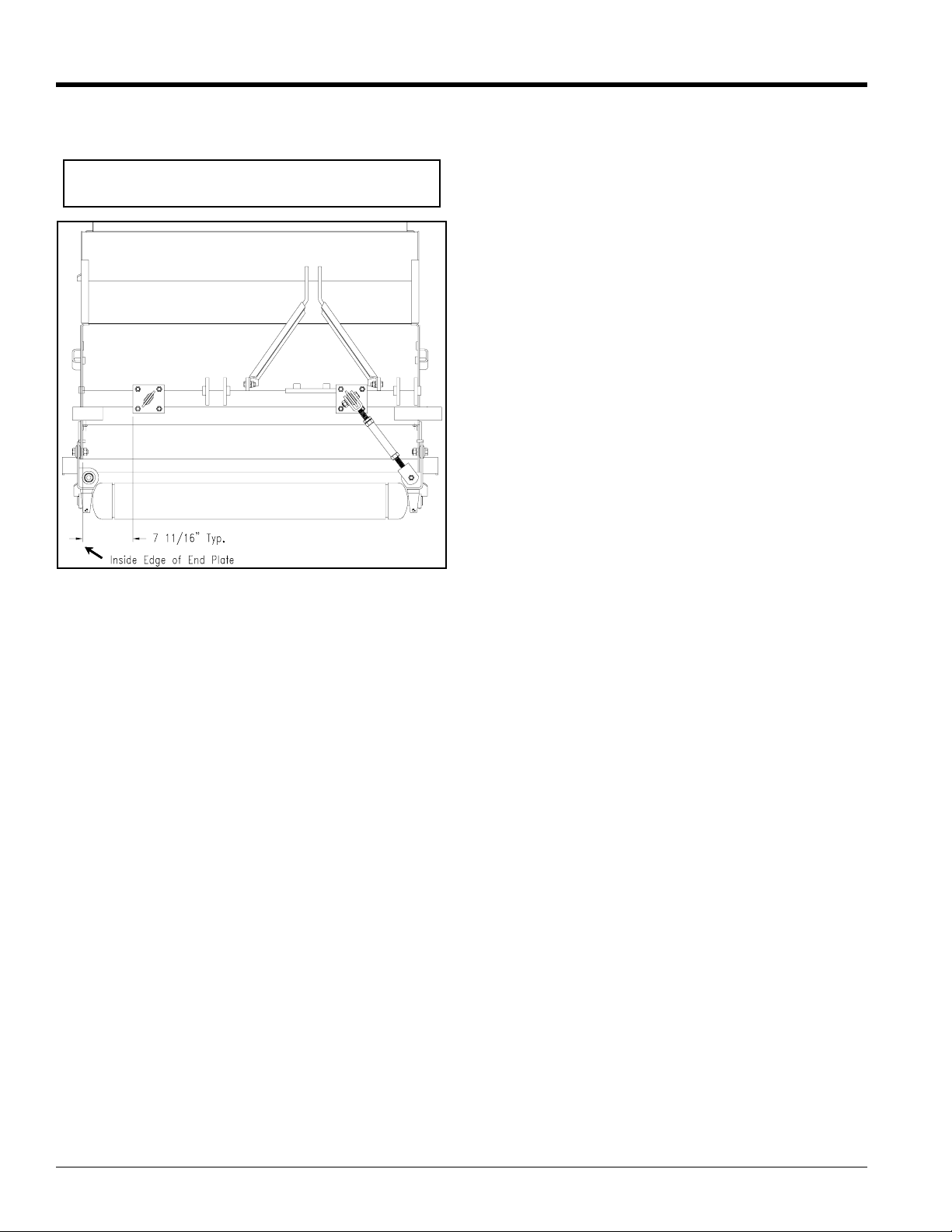
Refer to Figure 3:
Turnbuckle Mount should be Spaced 7 11/16" from inside edge
of end plates as shown.
NOTE: Although a 48" model Overseeder is shown,
dimensions will remain the same on a 72" model
.
Land Pride
12883
Turnbuckle Locations Typical on Both Ends of Seeder
Figure 3
Manual No. 308-305M 11/08/05
2
■
Page 3

Assembly Instructions
308-258A 15 Series 48" Overseeder Front Roller Assembl y
Your Kit Includes:
Qty. Part No. Part Description
1 308-247H FRONT ROLLER WELDMENT OS1548
2 308-252K TURNBUCKLE ASSY 12 3/8-17 7/8
2 308-253H UPPER TURNBUCKLE MOUNT
1 308-255H FRT ROLLER ARM WELDMENT OS1548
1 308-260H FLOATING TOP LINK
1 308-339D FLOATING TOP LINK SPACER TUBE
2 802-055C HHCS 5/8-11X2 GR5
4 802-058C HHCS 5/8-11X2 1/2 GR5
1 802-068C HHCS 3/4-10X4 GR5
4 802-091C HHCS 1/2-13X1 1/2 GR5
12 803-020C NUT HEX 1/2-13 PLT
6 803-021C NUT HEX 5/8-11 PLT
1 803-027C NUT HEX 3/4-10 PLT
12 804-015C WASHER LOCK SPRING 1/2 PLT
6 804-022C WASHER LOCK SPRING 5/8 PLT
1 804-023C WASHER LOCK SPRING 3/4 PLT
4 806-010C U-BOLT 1/2-13 X 2 1/2 X 3 1/2
2 822-094C BEARING PILLOW BLOCK 1 3/8BORE
Land Pride
308-259A 15 Series 72" Overseeder Front Roller Assembl y
Your Kit Includes:
Qty. Part No. Part Description
1 308-248H FRONT ROLLER WELDMENT OS1572
2 308-252K TURNBUCKLE ASSY 12 3/8-17 7/8
2 308-253H UPPER TURNBUCKLE MOUNT
1 308-256H FRT ROLLER ARM WELDMENT OS1572
1 308-260H FLOATING TOP LINK
1 308-339D FLOATING TOP LINK SPACER TUBE
2 802-055C HHCS 5/8-11X2 GR5
4 802-058C HHCS 5/8-11X2 1/2 GR5
1 802-068C HHCS 3/4-10X4 GR5
4 802-091C HHCS 1/2-13X1 1/2 GR5
12 803-020C NUT HEX 1/2-13 PLT
6 803-021C NUT HEX 5/8-11 PLT
1 803-027C NUT HEX 3/4-10 PLT
12 804-015C WASHER LOCK SPRING 1/2 PLT
6 804-022C WASHER LOCK SPRING 5/8 PLT
1 804-023C WASHER LOCK SPRING 3/4 PLT
4 806-010C U-BOLT 1/2-13 X 2 1/2 X 3 1/2
2 822-094C BEARING PILLOW BLOCK 1 3/8BORE
11/08/05
■
Manual No. 308-305M
3
Page 4

Corporate Office: P.O. Box 5060
Salina, Kansas 67402-5060 USA
www.landpride.com
 Loading...