

Page 1
Trailer, Fifth Wheel
Assembl y Instructions
Treker 4200/4400 NT/ST and 4210/4410 ST Series
Before You Start
When you see this symbol, the subsequent
instructions and warnings are serious - follow
!
without exception. Your life and the lives of
others depend on it!
IMPORTANT: Before you begin, read these
instructions and checkto be sure all parts and tools
are accounted for. Please retain these installation
instructions for future reference and parts ordering
information.
Your Trailer, Fifth Wheel is exclusively designed for your
Land Pride NT & ST Treker. Please read these
installation instructions and your NT & ST Treker
Operator’s Manual thoroughly before beginning.
Especially read information relating to safety concerns.
Also included in the Operator’s Manual is important
information on operation, adjustment, troubleshooting,
and maintenance for this attachment (some manual
sections do not apply to all accessories).
General Information
These assembly instructions apply to the following
Trailer, Fifth Wheel Accessories listed below:
701-154A Trailer Fifth Wheel
Assembly Instructions
Adetailedlistingof parts forthisaccessorykitis provided
on page 4. Use the list as a checklist to inventory parts
received.Please contact your local Land Pride dealer for
any missing hardware.
ALL DIRECTIONS REFERRING TO THE RIGHT AND
LEFT ARE WHEN THE OPERATOR IS ON THE
MACHINE.
!
Due to reduced ground clearance, remove Trailer Hitch
assembly before trail riding and when the Trailer is not in use.
Do not exceed 5 Mph when the Trailer is installed.
Use Extreme Caution on inclines or slopes
.This trailer is for cargo only.
Failureto follow these warnings could cause serious injury or
possibly death.
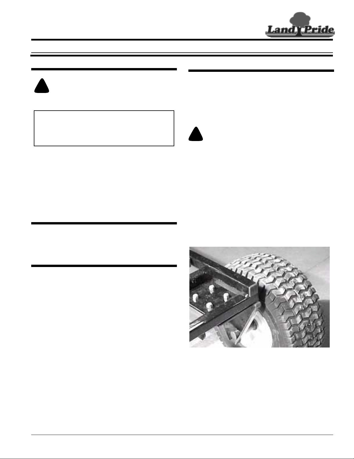
ASSEMBLY INSTRUCTIONS:
1. Using 5/16" x 3/4" Bolts (#21) and Nylock Locknuts,
providedin the parts bag,attach the WheelMounts (#17)
to the Trailer Bed (#4). See pictures below. Do not fully
tighten attaching hardware at this time.
WARNING
Manual No. 701-154M
Further Assistance
Your dealer wants you to be satisfied with your new
Trailer, Fifth Wheel. If for any reason you do not
understand any part of this manual or are not satisfied
with the service received, the following actions are
suggested:
1. Discuss the matter with your dealership service
manager making sure he is aware of any problems
youmayhave and that he has had the opportunity to
assist you.
2. If you are still not satisfied, seek out the owner or
general manager of the dealership, explain the
problem and request assistance.
3. For fur ther assistance wr ite to:
Land Pride Service Department
1525 East North Street
P.O. Box 5060
Salina, Ks. 67402-5060
E-mail address
lpservicedept@landpride.com
© Copyright 2007 Printed
06/25/07
1
Page 2
Assembly Instructions
Land Pride
Two Machine Bushings (# 18)
Two Machine Bushings (# 18)
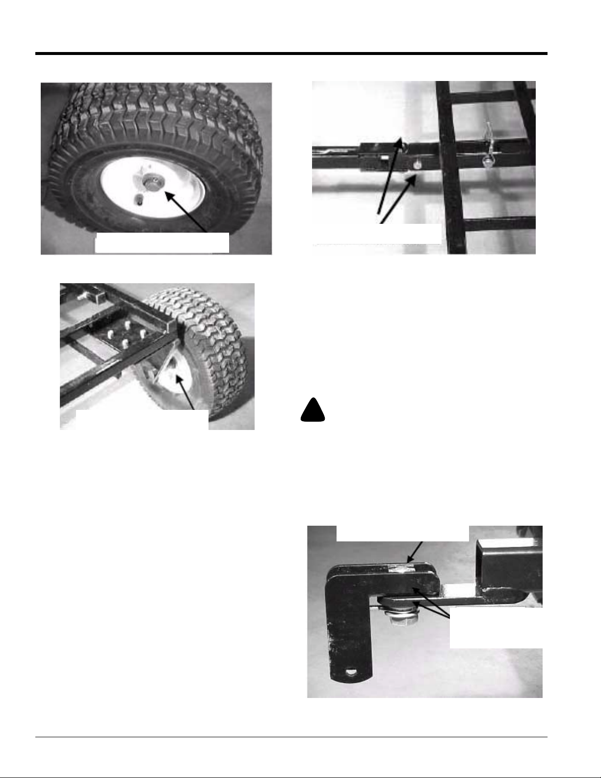
2. Place two 1" x 1-1/2" Machine Bushings (#19) on the
Wheel Mount (#17) shaft. Slide the Wheel (#18) on the
Wheel Mount (#17). Slide another two 1" x 1-1/2"
Machine Bushings (#19) on the Wheel Mount (#17)
shaft. Secure the Wheel assembly with one 5/32" x 1-1/
2" Cotter Pin (#20). Repeat this step on the other side.
Note: You may only need toinstall some of the Machine
Bushings (#19). Only use enough Machine Bushings
(#19) to ensure a snug wheel fit.
Must Pivot At These two Points
3. Place the Pivot Tube (#3) between the front support
rails as shown in thepicture aboveand attachusing one
of the 3/8" x 2-1/4" Bolts (#12) and Nylock Locknuts
provided. Tighten fully and then back off turn or just until
the Pivot Tube (#3) can rotate inside the support rails.
4. Install one of the 3/8" 2-1/2" Lock Pins (#8) in the rear
hole of the Pivot Tube (#3) as shown and then attach the
TrailerTongue (#2) usingthe remaining 3/8"x 2-1/4"Bolt
(#12) and Nylock Lock Nut. Tightent securely and then
backoff turnor justuntil the railerTongue (#2) canrotate
side to side.
!
CAUTION
Be aware that the GOUND CLEARANCE of your machine is
reduced. This could result in a loss of control of your machine
and cause injury or death. Do not exceed 5 Mph with the hitch
installed and remove it before trail riding.
Square Nut ALWAYS
goes inside of channel.
SquareNutAlwaysGoesInside
of Channel
One Flatwasher (#14)
Above The Eyebolt
(#8) & One Below
Manual No. 701-154M 06/25/07
2
■
Page 3

Assembly Instructions
5. The hitch comes already assembled. Mount the Hitch
(#1) in the mannerthat willposition the trailer pin hole at
11 inches or more from the ground.
Note: On most machines the hitch will be mounted as
shown above.
6. Make sure the Hitch (#1) is straight in line with the
center of the Machine. First tighten the 3/4" x 2" Bolt
(#14) just enough to take out the free play. Then tighten
the 5/16" Eyebolt (#9) until it actually begins to draw the
Hitch(#1) intothe Rear ReeseHitch (701-017A).Tighten
the Eyebolt (#9) an additional turn and then FULLY
tighten the 3/4" x 2" Bolt (#14).
Land Pride
7. Connect the Trailer to the Hitch Assembly using the
remaining 3/8" x 2- 1/2" Lock Pin (#8) as shown in the
picture above.
06/25/07
■
Manual No. 701-154M
3
Page 4

Land Pride
Listing of Parts
Kit No. 701-034A BACK SCREEN NT
Item Part No. Part Description Qty
1 PTL102 HITCH 1
2 PTL103 TRAILER TONGUE 1
3 PTL104 PIVOT TUBE 1
4 PTL105 TRAILER BED 1
5 PTL106 BED EXTENSION 1
6 PTL107 TAIL GATE 1
7 805-212C PIN WIRE SNAP LOCK 3/8 X 2 1/2 2
8 EB516WD 5/16" EYE BOLT WELDED 1
9 804-010C WASHER FLAT 5/16 USS PLT 1
10 802-131C HHCS 5/16-18X3 GR5 4
11 802-114C HHCS 3/8-16X2 1/2 GR5 2
12 SP34-14 5/16"X3/4"X1/4" NYLON SPACER 4
13 802-064C HHCS 3/4-10X2 GR5 1
14 804-025C WASHER FLAT 3/4 SAE PLT 2
15 CAPSQ TUBE PLUGS 28
16 10307 WHEEL MOUNT 2
17 CSY325 WHEEL 2
18 MB1121 1"X1 1/2" MACHINE BUSHING 8
19 805-089C PIN COTTER 5/32 X 1 1/2 LONG 2
20 802-007C HHCS 5/16-18X3/4 GR5 8
4
Manual No. 701-154M 06/25/07
■
 Loading...