

Page 1
Wiring Harness Update Kit
Assembly Instructions
Razor Series ZR44 & ZR52
Before You Start
When you see this symbol, the subsequent
instructions and warnings are serious - follow
!
without exception. Your life and the lives of
others depend on it!
These instructions contain only information required to
assemble the Wiring Harness Kit to the Razor Series
ZR44 & ZR52 Riding Mowers. A detailed Operator’s
Manual was supplied with the Razor. Refer to the
Operator’s Manual for additional specific information
especially information relating to safety concerns. Also
included in the Operator’s Manual is important
information on operation, adjustment, troubleshooting,
and maintenance for this attachment (some manual
sections do not apply to all options).
A separate Parts Manual for replacement parts can be
purchasedfromyour dealer or available free of charge at
www.landpride.com. Have model and serial numbers
handy when placing an order.
Manual Part Numbers:
• Operator’sManual . . . . . . . . . . . . . . . . . .356-059M
• Parts Manual . . . . . . . . . . . . . . . . . . . . . . . 356-059P
Manual No. 356-141M
Instructions For Kit No 356-142A
A detailed listing of parts for wiring harness update kit
No. 356-142A is provided on page 4. Use this list as a
checklist to inventory parts received.
1. Parkmower on a flat surface and movecontrol levers
to park.
2. Turn off engine and remove ignition key.
3. Raise seat deck fully up.
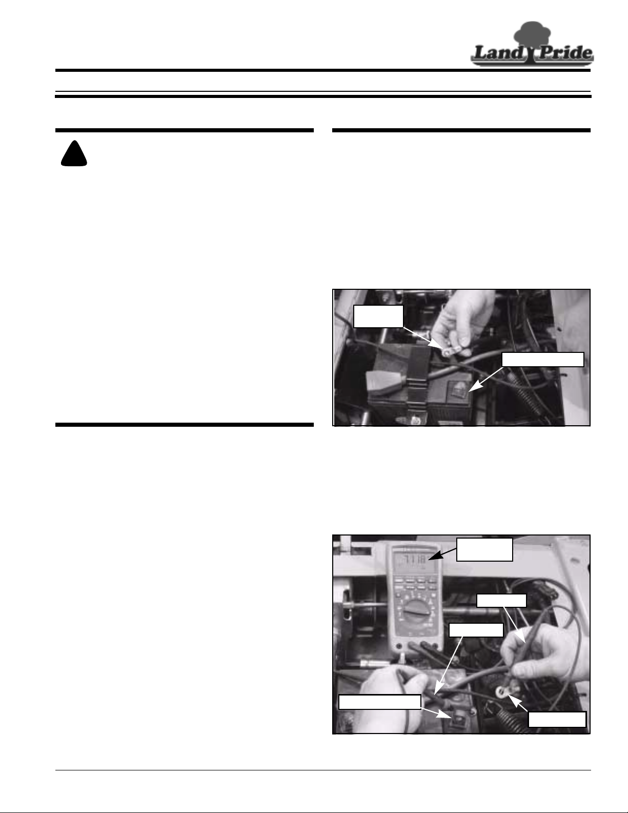
Refer to Figure 1:
4. Disconnect negative ground wire (black wire) from
the batter y’s negative post ( - ). Place ground wire in
a location where it cannot touch the battery posts.
Negative
Ground
Negative Post (-)
General Information
SomeZR44&ZR52Razorsmaybeexperiencingasmall
drain on the battery when units are parked and the
ignition off. Over time this small electrical drain can
deplete the battery to a point that it fails to start the
mower. If a unit is experiencing a repeated battery
discharge for no obvious reason, installation of this
simple kit will eliminate that condition.
These assembly instructions apply to the Razor ZR44
and ZR52 Kit Number:
356-142A RAZOR HARNESS UPDATE KIT
Tools required:
Electrical Tape
•
• Wire Cutters
• Wire Stripper
• Electrical Wire Crimpers
• Two 10 mm Metric Wrenches
• Terminal Removal Tool or
a Small Thin Bladed Screw Driver
23811
Remove Ground Battery Connection
Figure 1
Refer to Figure 2:
5. Check battery drain with an amp meter by placing
black probe on the negative battery post and red
probe on the ground wire as shown. A drain of 7
milliamps or more is an indication that it would be
helpful to install this wiring harness kit.
7 milliamps
or greater
Red Probe
Black Probe
Negative Post (-)
Ground wire
23812
© Copyright 2005 Printed
1/16/07
Battery Drain Check
Figure 2
■
Manual No. 356-141M
1
Page 2
Instructions For Kit No 356-142A
Land Pride
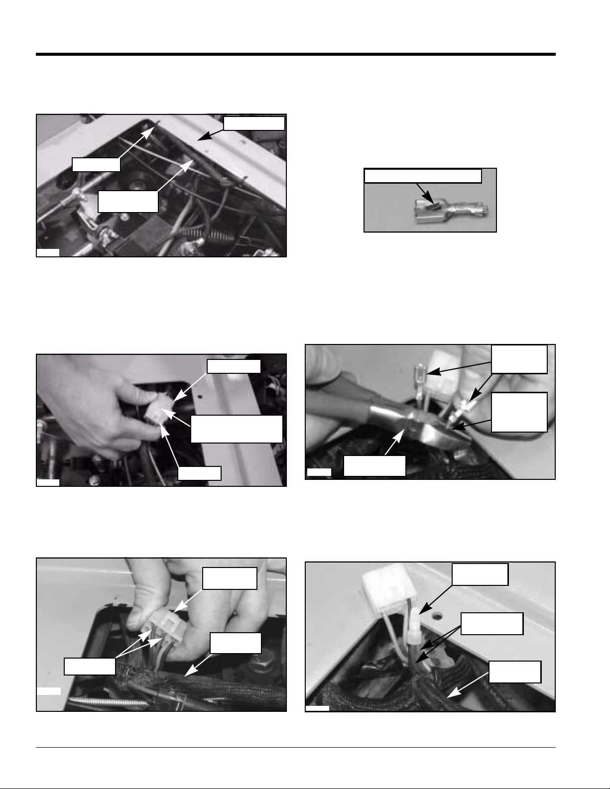
Refer to Figure 3:
6. Locate main wiring harness attached to the mower
frame. Cut plastic ties secur ing harness in place.
Mower Frame
Plastic Tie
Main Wiring
Harness
23813
Locate Wire Harness
Figure 3
Refer to Figure 4:
7. Pullwhite connector out from under backr ight corner
of mower frame.
8. Unplug connector by pressing down on the center
tab and pulling the two ends apart.
Female End
10. Insert terminal removal tool or small thin bladed
screw driver into backside (see Figure 5) of a purple
wire connector slot. Push in on the purple wire and
press down on the holding tab. See Figure 6 below
for view of holding tab. Once the tab has released,
pull purple ground wire out. If the terminal does not
release, reposition terminal tool and pull on the wire
again.
Spade Terminal Holding Tab
24595
Spade Terminal Holding Tab
Figure 6
11. Repeat step 10 to remove second purple ground
wire.
Refer to Figure 7:
12. Cut both purple wires close to the spade terminals.
Cutting close will leave enough wire to install butt
connector in step 13 below.
Spade
Terminals
Press Here to
Unplug Connector
Male End
23814
Unplug Connector
Figure 4
Refer to Figure 5 & Figure 6:
9. Locate two purple ground wires leading from the
connector to the main wiring harness.
Backside of
Connector
MainWiring
Harness
Purple Wire
23815
Cut Close
to Spade
Terminals
23816
Wire Cutters
Cutting Spade Terminals Off
Figure 7
Refer to Figure 7:
13. Strip 3/8" length of outer covering from both ends of
purple ground wires. Twist wire ends together and
twist-on butt connector.
Butt
Connector
Two Purple
Ground Wires
Main Wiring
Harness
23819
Remove Purple Ground Wires
Figure 5
2
Installing Butt Connector
Figure 7
Manual No. 356-141M 1/16/07
■
Page 3

Land Pride
Instructions For Kit No 356-142A
Refer to Figure 8:
14. Crimp Butt Connector with crimping part of wire
strippers to secure connector place.
Butt
Connector
Main Wiring
Harness
Crimp Portion of
the Wire Strippers
24594
Crimping Butt connector
Figure 8
Butt
Connector
Main Wire
harness
Refer to Figure 9:
15. Plug the new splice wire spade terminals into the
terminal slots where the purple ground wires were
removed.
New Splice Wire
Terminal Ends
Orange
Wire
Splice
Connector
Bare Wire
End of New
Splice Wire
Splice
Connector
cover
Figure Description
Figure 10
Metal
Prong
23818
Refer to Figure 11:
21. Reattach main wiring har ness to mower frame with
new plastic ties.
22. Check battery drain as outlined in step 5 before
reconnecting battery ground wire. Amp reading
should not exceed .001 milliamps.
23. Reconnect battery ground wire to negative post (-).
23817
Plug Splice Wire Into Connector
Figure 9
Bare Wire End
Refer to Figure 10:
16. Insert bare wire end of new splice wire into splice
connector as shown.
17. Locate orange wire leading into main wiring harness
and attach splice connector over orange wire as
shown.
IMPORTANT: Force metal prong down with pliers
beforeclosing splice connector cover.Forcing prong
down with cover will damage the splice connector.
18. Make certain bare wire end is fully inserted into the
splice connector and then force metal prong down
into the connector with pliers.
19. Close splice connector cover. Make certain it snaps
shut.
20. (Optional) Press Butt Connector against main wire
harness and secure in place with electrical tape.
1/16/07
■
Negative
Ground Wire
Negative Post ( - )
21127
Figure Description
Figure 11
24. Lowerseatdeckandstart mower to verify it will start.
Shut mower off and lock seat down to complete
installation.
Manual No. 356-141M
3
Page 4

Razor Harness Update Kit Part No. 356-142A
Qty. Part No. Part Descr iption
1 356-141M INSTRUCTION,HONDA ELEC UPDATE
2 800-112C CABLE TIE .19X7.25 1.75D 50LB
1 833-401C HARNESS UPDATE WIRE Kit
1 833-381C BUTT CONNECTOR (Included with 833-401C Kit)
1 833-460C CONNECTOR SPLICE 16-14AWG (Included with 833-401C Kit)
Corporate Office: P.O. Box 5060
Salina, Kansas 67402-5060 USA
www.landpride.com
 Loading...