

Page 1
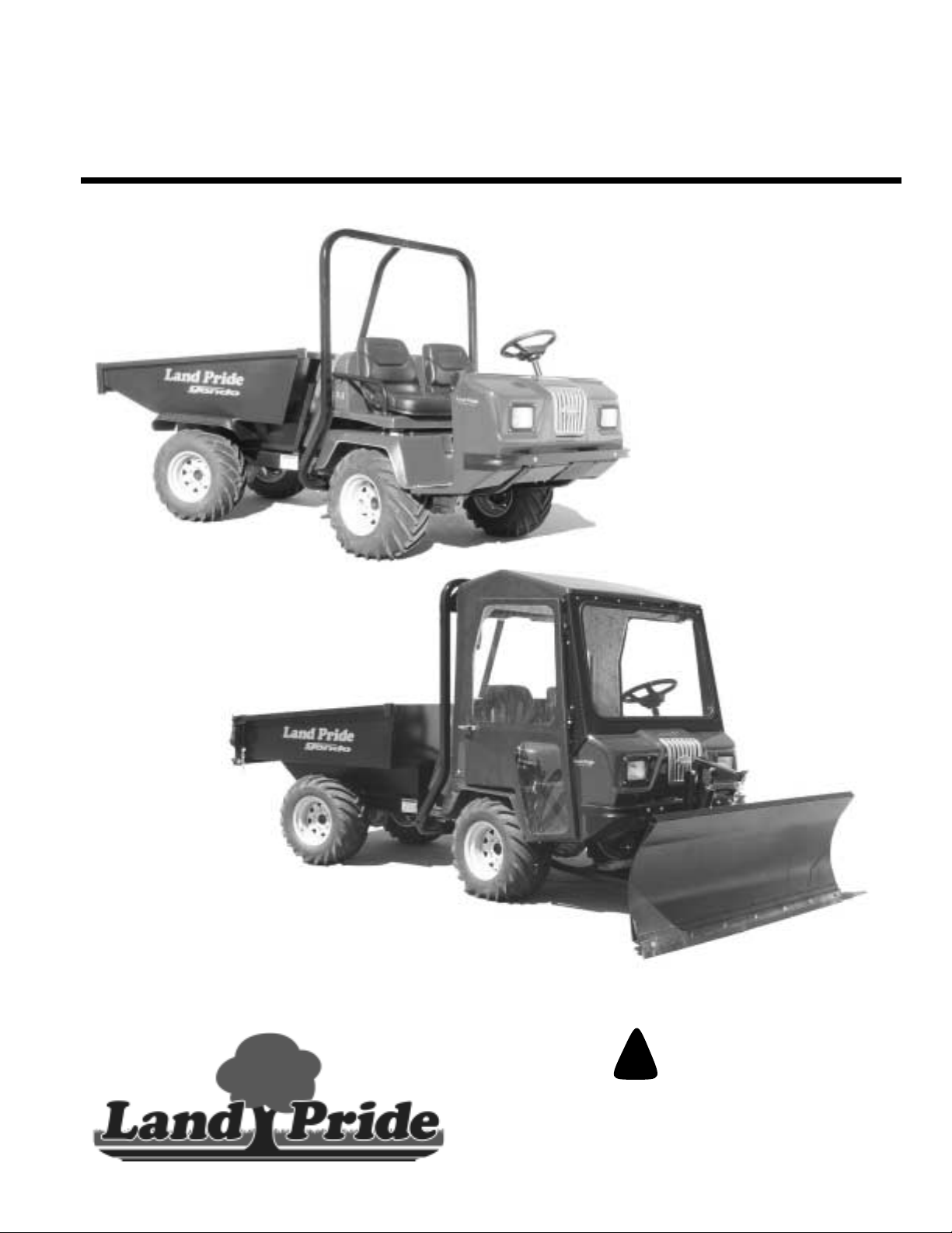
Table of Contents
Gondo
4400EX Heavy Duty Off Road Utility Vehicle
22081
22076
720-132M
Operator’s Manual
For Serial Numbers 407616-407618, 409626 and 421461+
Read the Operator’s manual entirely. When
you see this symbol, the subsequent
!
instructions andwarningsare serious - follow
without exception. Your life and the lives of
others depend on it!
© Copyright 2004 Printed
Cover photo may show optional equipment
not supplied with standard unit.
7/01/05
Page 2

Table of Contents
Section 1 Introduction . . . . . . . . . . . . . . . . . . . . . . . 1
Safety First . . . . . . . . . . . . . . . . . . . . . . . . . . . . . . . . 1
Using This Manual . . . . . . . . . . . . . . . . . . . . . . . . . . 1
Terminology . . . . . . . . . . . . . . . . . . . . . . . . . . . . . 1
Definitions . . . . . . . . . . . . . . . . . . . . . . . . . . . . . . . 1
Application . . . . . . . . . . . . . . . . . . . . . . . . . . . . . . . . 1
Models Covered . . . . . . . . . . . . . . . . . . . . . . . . . . 1
Getting Acquainted with your Gondo . . . . . . . . . . 1
Owner Assistance . . . . . . . . . . . . . . . . . . . . . . . . . . 2
Serial Number Plate . . . . . . . . . . . . . . . . . . . . . . . . . 2
Section 2 Important Safety Information . . . . . . . . . 3
Safety Symbol . . . . . . . . . . . . . . . . . . . . . . . . . . . . . 3
Safe Operating Procedures . . . . . . . . . . . . . . . . . . . 5
Safety Decals . . . . . . . . . . . . . . . . . . . . . . . . . . . . . . 7
Section 3 Pre-Delivery and Check List . . . . . . . . . 12
Pre-Delivery Certificate . . . . . . . . . . . . . . . . . . . . . 12
Vehicle Information . . . . . . . . . . . . . . . . . . . . . . . 12
Dealer Service and Inspection List . . . . . . . . . . . 12
Dealer Test Ride List . . . . . . . . . . . . . . . . . . . . . 12
Dealer Delivery To Customer List . . . . . . . . . . . . 13
Customer Acceptance List . . . . . . . . . . . . . . . . . 13
Section 4 Operating Instructions . . . . . . . . . . . . . . 14
Operator Responsibilities . . . . . . . . . . . . . . . . . . . . 14
Pre-Start Check List . . . . . . . . . . . . . . . . . . . . . . 14
General Operation . . . . . . . . . . . . . . . . . . . . . . . . . 14
Starting the Engine . . . . . . . . . . . . . . . . . . . . . . . 14
Dashboard Switches and Instruments . . . . . . . . 14
Foot Operated Controls . . . . . . . . . . . . . . . . . . . 15
Hand Operated Controls . . . . . . . . . . . . . . . . . . . 16
Engine Hood Release . . . . . . . . . . . . . . . . . . . . . 16
Fuel Indicator . . . . . . . . . . . . . . . . . . . . . . . . . . . 17
Steering . . . . . . . . . . . . . . . . . . . . . . . . . . . . . . . 17
Seat Belts . . . . . . . . . . . . . . . . . . . . . . . . . . . . . . 17
Driving Conditions . . . . . . . . . . . . . . . . . . . . . . . . . 18
Towing the Gondo . . . . . . . . . . . . . . . . . . . . . . . . . 19
Towing Without a Trailer . . . . . . . . . . . . . . . . . . . 19
Towing Loaded on a Trailer . . . . . . . . . . . . . . . . . 19
Traveling Tips From the Trail Masters . . . . . . . . . . 20
Section 5 Options and Accessories . . . . . . . . . . . 22
Gondo Options . . . . . . . . . . . . . . . . . . . . . . . . . . . . 22
Dump Bed Option . . . . . . . . . . . . . . . . . . . . . . . . 22
Tailgate Operation (Cargo box option only) . . . . 22
Tires . . . . . . . . . . . . . . . . . . . . . . . . . . . . . . . . . . 22
Gondo Accessories . . . . . . . . . . . . . . . . . . . . . . . . 23
Section 6 Maintenance . . . . . . . . . . . . . . . . . . . . . .24
General Maintenance . . . . . . . . . . . . . . . . . . . . . . .24
Prepare Vehicle for Maintenance . . . . . . . . . . . . . . 24
Torque Values . . . . . . . . . . . . . . . . . . . . . . . . . . . . .24
Tire Maintenance . . . . . . . . . . . . . . . . . . . . . . . . . .25
Jacking the Vehicle . . . . . . . . . . . . . . . . . . . . . . . . .25
Seat Belts . . . . . . . . . . . . . . . . . . . . . . . . . . . . . . . .25
Electrical System . . . . . . . . . . . . . . . . . . . . . . . . . .26
Battery . . . . . . . . . . . . . . . . . . . . . . . . . . . . . . . . . .26
Jump Starting the Battery . . . . . . . . . . . . . . . . . . . .26
Prepare Vehicle to Jump-Start . . . . . . . . . . . . . . .26
Connecting Jumper Cables . . . . . . . . . . . . . . . . .27
Disconnecting Jumper Cables . . . . . . . . . . . . . . .27
Fuel System . . . . . . . . . . . . . . . . . . . . . . . . . . . . . .27
Engine Maintenance . . . . . . . . . . . . . . . . . . . . . . . .29
General Information . . . . . . . . . . . . . . . . . . . . . . .29
High Altitude Carburetor Kit . . . . . . . . . . . . . . . . .29
Power Steering Belt . . . . . . . . . . . . . . . . . . . . . . . .29
Engine Air Filter . . . . . . . . . . . . . . . . . . . . . . . . . . .30
Spark Arrester . . . . . . . . . . . . . . . . . . . . . . . . . . . .31
Maintenance Schedule . . . . . . . . . . . . . . . . . . . . . .32
Section 7 Lubrication and Fluids . . . . . . . . . . . . . . 33
Engine Oil . . . . . . . . . . . . . . . . . . . . . . . . . . . . . . . .33
Differential Oil . . . . . . . . . . . . . . . . . . . . . . . . . . . . .35
Transmission Fluid . . . . . . . . . . . . . . . . . . . . . . . . .36
Brake Fluid . . . . . . . . . . . . . . . . . . . . . . . . . . . . . . .37
Steering & Cargo Lift Cylinder Fluid . . . . . . . . . . . .37
Grease Type Lubrication . . . . . . . . . . . . . . . . . . . . .38
Driveline U-Joints . . . . . . . . . . . . . . . . . . . . . . . .38
Pillow Block Bearing . . . . . . . . . . . . . . . . . . . . . .38
Rotating Bearing Surfaces . . . . . . . . . . . . . . . . . .38
Section 8 Seasonal Storage . . . . . . . . . . . . . . . . . .39
Engine Preparation for Storage . . . . . . . . . . . . . .39
Vehicle Storage Preparation . . . . . . . . . . . . . . . .39
Vehicle Removal From Storage Preparation . . . .39
Section 9 Body Repair . . . . . . . . . . . . . . . . . . . . . . .40
Introduction . . . . . . . . . . . . . . . . . . . . . . . . . . . . . . .40
Light Scuff . . . . . . . . . . . . . . . . . . . . . . . . . . . . . . . .40
Scratch . . . . . . . . . . . . . . . . . . . . . . . . . . . . . . . . . .40
Deep Gouge . . . . . . . . . . . . . . . . . . . . . . . . . . . . . .41
Section 10 Specifications and Capacities . . . . . . .42
Section 11 Features And Benefits . . . . . . . . . . . . .43
Section 12 Troubleshooting . . . . . . . . . . . . . . . . . .44
Section 13 Appendix . . . . . . . . . . . . . . . . . . . . . . . . 48
Torque Values Chart . . . . . . . . . . . . . . . . . . . . . . . .48
Land Pride Limited Warranty . . . . . . . . . . . . . . . . .49
© Copyright 2004 All rights Reserved
LandPride providesthis publication“as is”without warrantyof anykind, eitherexpressedor implied.While everyprecaution hasbeen takenin thepreparation ofthis manual,
Land Pride assumes no responsibility for errors or omissions. Neither is any liability assumedfor damages resulting from theuse of the information contained herein.Land
Pride reserves the right to revise and improve its products as it sees fit. This publication describes thestate of this product at the time of its publication, and may not reflect
the product in the future. The illustrations in this manual are not intended for safe and proper assembly or disassembly of equipment. The illustrations are intended for
ordering parts only.
Land Pride is a registered trademark.
All other brands and product names are trademarks or registered trademarks of their respective holders.
Printed in the United States of America.
4400EX Heavy Duty Off Road Utility Vehicle 720-132M
7/01/05
Page 3
Table of Contents
Section 1 Introduction
Section 1 Introduction
Land Pride welcomes you to its growing family of new
productowners.Gondoseries trucks are heavy duty utility
vehicles that have been designed with care andbuilt by
skilled workers using quality materials. Proper set-up,
maintenance and safe operating practices will help you
get years of satisfactory use from this vehicle.
Safety First
Land Pride is fully aware of the need for safe operating
procedures around all of our equipment. We hope you will
make a sincereeffort to put safety above all other
priorities. The Gondo is designed and builtfor serious
work, recreation and enjoyment; however, improper and
irresponsible operation could resultin serious injury or
death. Since this is an off-road vehicle, operators will
seldom see the road safety and warning signs they are
accustomed to seeing on highways and public streets.
This places additional responsibility on the driver to
operate this vehicle well within the safe operational limits
and capabilities of the unit.
This manual has been prepared to instruct you in the safe
and responsible operation of your Gondo. Please read
andabide by all safetyalert information aboutthis vehicle.
If you do not understand any part of this manual, contact
your local dealerfor additional information and
clarification. As the operator of this piece of equipment,
you are incomplete control. Only you can prevent an
accident from happening!
Using This Manual
Prior to any vehicle operation it is absolutely essential
•
that you read and comprehend each section in this
manualtodevelopanunderstandingofyourvehicleand
safetypractices.Afterreviewingthismanual,storeitina
dry and easily accessible place for future reference.
• The Operator’s Section is designed to help familiarize
you with safety, assembly, operation, adjustments,
troubleshooting and maintenance. Read this manual
and follow the recommendations to help ensure safe
and efficient operation.
• The information contained within this manual was
current at the time of printing. Some parts may change
slightly to assure you of the best performance.
• To order a new Operator’s orParts Manual contactyour
authorized dealer. Manuals can also be downloaded,
free-of-charge from our website at www.landpride.com
orprintedfromtheLandPride Service & Support Center
by your dealer.
Terminology
Right-hand and left-hand as used in this manualare
determined by facing the direction the vehicle will travel
while in use unless otherwise stated.
Definitions
The following terms are used throughout this manual.
IMPORTANT: A special point of information related to
its preceding topic. Land Pride’s intention is that this
information should be read and noted before
continuing.
NOTE:Aspecialpoint of information that the operator
must be aware of before continuing.
Application
Models Covered
4400EX
Getting Acquainted with your Gondo
The Land Pride Gondo is an extreme utility vehicle
designed exclusively for off-road use. It is not designed,
properly equipped, or licensed to be safely operated on
public streets andhighways. This 2200lb. payload hauler
is designed to carry two people in the cab and a generous
amount of cargo, gear, and supplies safely and
conveniently over extremely difficult or rough terrain.
The Gondo features center articulating power steering
coupled with a pivoting interactive frame for unexcelled
terrain hugging capability and maximum traction. Traction
capabilitiesare evenfurther maximized with incorporation
of full-time shaft driven four-wheeled drive. The Gondo is
poweredby the proven624cc 20hp KohlerCommand Pro
Series Engine and a fully automotivespeed synchromesh
manual transmission. Engaging the eight-inch manual
clutch delivers power to the automotive grade front and
rear open differentials.
TheGondoisequipped with highly dependable fourwheel
hydraulically activated automotive drum type brakes. A
manual park brake is included as standard equipment.
Engine braking is inherently available through the
standard transmission when needed for traveling down
steepor slippery andtreacherous grades.All fourtires are
26x12-12 4-ply and are available with turf or bar type
tread.
The Gondo frame is tractor tough and constructed out of
welded and formed heavy wall tubing that is coated with a
durableblacksatin powder paint finish. A certifiedrollover
protection system (ROPS) with seat belts is standard
equipment. (But may be left off by customer’s choosing.)
The console body and optional cab are constructed of
extratough fiberglass withanattractivegel coat finish. The
high capacity cargo beds are made of welded and formed
heavygauge sheet metal finished with black satin powder
7/01/05
4400EX Heavy Duty Off Road Utility Vehicle 720-132M
1
Page 4
Section 1 Introduction
Table of Contents
paint. Customers can choose either a 23 cu. ft.capacity
gondola style box or an 18 cu. ft. capacity tilt box with a
standard tailgate. Choosing the hydraulic tilt option
makesboth boxescapableof hydraulically dumping their
full 1800lb. payload capacity by simple activation of a
leveron the operator’sconsole.A standard receiver type
hitch comes as standard equipment and this unit is
capable of upto 2500 lbs. of towing capacity.
The operator’sstation is a cab-forward style console that
hingesforwardandhas aft suspensionovertwocoil-over
shocksprovidinga smoother rideandincreasedoperator
andpassenger comfort. Twocushioned high back bucket
seats are provided as standard equipment and seatbelts
are also standard for units equipped with a ROPS. The
operators console is equipped with a standard hour
meter,voltmeter,12voltkeyedignition,andlightswitchto
activate the two standard halogen beam headlights.
Customers needing additional protection from the
elements and surrounding environment can also order
additional accessories such as cabs with safety glass
windshields, powered wipers, and soft sided cab doors.
Snowplowsandlog skidders are also availablefor added
versatility.
Whetheryouarehauling big game, farmingtools,hunting
and fishing camp supplies, construction equipment,
livestock feed, military cargo, or fire fighting and rescue
equipment, the Gondo is capable of getting youand your
cargothere and back over tough and extremeterrainand
in all kinds of weather.
Owner Assistance
The safety video should be viewed by the owner and the
Warranty Registration card should be filled outby the
dealer at the time of purchase. The owner should also
receive a copy of the safety video upon purchasing the
vehicle as well as have participated in a short drivers
training course with the dealer. This information is
necessary to provide you with quality customer service.
Theparts on your Gondo HeavyDutyUtility Vehiclehave
been specially designed and should only be replaced
with genuine Land Pride parts.
If customer service or repair parts are required contact a
Land Pride vehicle dealer. They have trained personnel,
genuine repair parts and equipment specially designed
to repair Land Pride products.
Serial Number Plate
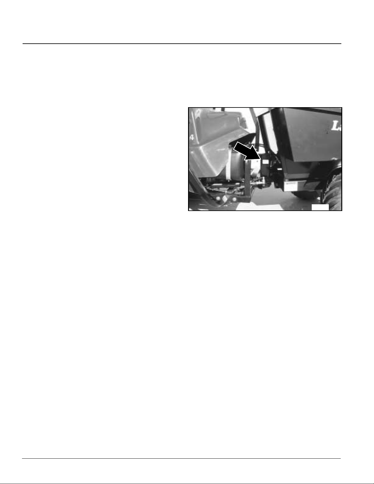
Refer to Figure 1
Always use serial andmodel number when ordering
parts from your Land Pride dealer. The serial-number
plate is located on the driver’s side on the center swivel
yoke as shown below.
21469
Serial Number Plate
Figure 1
Record your vehicle model number (4400EX) and serial
number here for quick reference:
Model Number:___________________________
Serial Number: ___________________________
YourLandPridedealerwantsyoutobesatisfiedwithyour
new vehicle. If you do not understand any part of this
manual or are not satisfied with the service received,
please take the following actions.
1. Discuss the matter with your dealership service
manager.Makesuretheyareawareof any problems
so they can assist you.
2. If you are still unsatisfied, seek out the owner or
general manager of the dealership.
3. For further assistance write to:
Product Support
Land Pride Service Department
1525 East North Street
P.O.Box 5060
Salina, Ks. 67402-5060
4400EX Heavy Duty Off Road Utility Vehicle 720-132M
2
E-mail address
7/01/05
Page 5
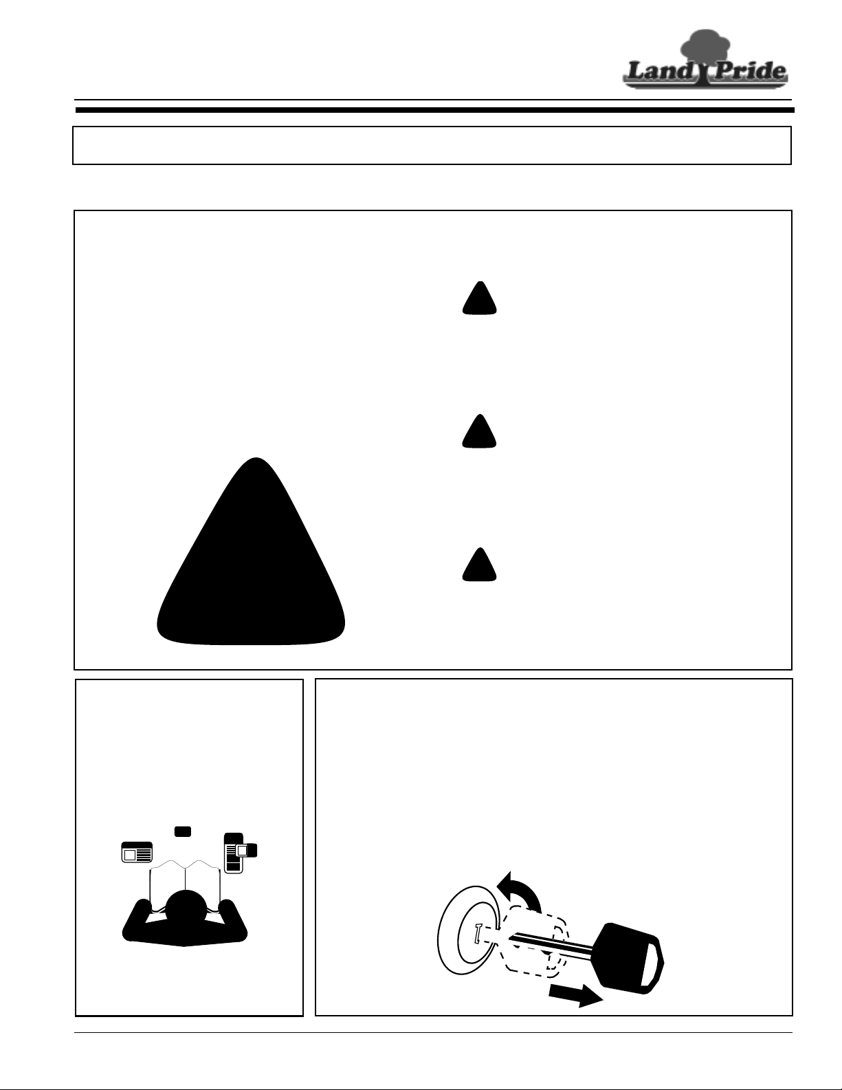
Table of Contents
Section 2 Important Safety Information
Section 2 Important Safety Information
IMPORTANT: Read and understand all pages in this manual thoroughly before operating y our vehicle.
These are common practices that may or may not be applicable to the products described in
this manual.
Safety Symbol
Look for the Safety symbol throughout this
manual.TheSAFETY ALERTSYMBOLindicates
there is a potential hazard to personal safety
involved and extra safety precaution must be
taken. When you see this symbol, be alert and
carefully read the message that follows it. In
additiontodesignandconfigurationof equipment,
hazard control and accident prevention are
dependent upon the awareness, concern,
prudence and proper training of personnel
involved in the operation, transport, maintenance
and storage of equipment.
!
Be Aware of Signal Words
Signal words designate a degree or level of
hazard seriousness. The signal words are:
!
DANGER
DANGERindicates animminentlyhazardous situation
which, if not avoided, will result in serious injury or
death. This signal word is limited to the most extreme
situations, typically for vehicle components that, for
functional purposes, cannot be guarded.
!
WARNING
WARNINGindicates a potentially hazardous situation
which, if not avoided, could result in death or serious
injury, and includes hazards that are exposed when
guards are removed. It may also be used to alert
against unsafe practices.
!
CAUTION
CAUTIONindicates a potentially hazardous situation
which, if not avoided, may result in minor or moderate
injury. It may also be used to alert against unsafe
practices.
For Your Protection
▲ Thoroughly read and understand
the “Safety Decal” section, read all
instructions noted on the decals.
7/01/05
Before Operating
▲ This Gondo Heavy Duty Utility
Vehicle is not to be driven on
public roads.
▲ Do not operate this vehicle under
the influence of alcohol or drugs.
▲ Always inspect the vehicle before
operating it. See "Pre-Start Check
List" on page 14.
OFF
4400EX Heavy Duty Off Road Utility Vehicle 720-132M
▲ Do not operate this machine
unless all safety shields are in
place and all badly worn, broken or
missing parts have been properly
replaced.
▲ Wear appropriate protective gear
and clothing such as safety
helmet, goggles, gloves, coveralls,
etc., when conditions warrant.
▲ No driver under age of 16.
3
Page 6
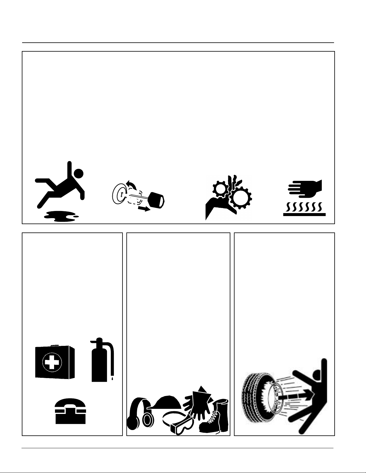
Table of Contents
Section 2 Important Safety Information
Practice Safe
Maintenance
▲ Understand procedure before
doing work. Use proper tools and
equipment.Refertothis manual for
additional information.
▲ Work in a clean, dry area.
▲ Place the vehicle in neutral, set
parking brake, turn off engine and
remove key before performing
maintenance. Chock wheels if you
must perform maintenance on a
slope.
▲ Make sure all moving parts have
stopped and all system pressure is
relieved.
▲ Allow the engine to cool
completely.
▲ Disconnect battery ground cable
(-) before servicing or adjusting
electrical systems or before
welding.
OFF
▲ Inspect all parts. Make sure parts
are in good condition and installed
properly.
▲ Remove build-up of grease, oil or
debris.
▲ Removealltools and unused parts
from the Gondo before operation.
Prepare for
Emergencies
▲ Be prepared if a fire starts.
▲ Keep a first aid kit and fire
extinguisher handy.
▲ Keep emergency numbers for
doctor, ambulance, hospital and
fire department near phone.
Wear Pr otective
Equipment
▲ Wear protective clothing and
equipment.
▲ Wear clothing and equipment
appropriate for the job. Avoid
loose-fitting clothing.
▲ Because prolonged exposure to
loud noise can cause hearing
impairment or hearing loss, it is
best to wear suitable hearing
protection such as earmuffs or
earplugs.
▲ Because operating equipment
safely requires your full attention,
avoid wearing radio headphones
while operating machinery.
▲ It is the discretion of the operator
and passenger to wear Seat Belts
when available.
Tire Safety
Tire changing can be dangerous
and should be performed by trained
personnel using correct tools and
equipment.
▲ When inflating tires, use a clip-on
chuck and extension hose long
enough for you to stand to one
side–not in front of or over tire
assembly. Use a safety cage if
available.
▲ When removing and installing
wheels, use wheel-handling
equipment adequate for weight
involved.
911
4400EX Heavy Duty Off Road Utility Vehicle 720-132M
4
7/01/05
Page 7
Table of Contents
Section 2 Important Safety Information
Safe Operating Procedures
Thesafeoperationofanymachinery is a big concern to all
consumers. Your Gondo has been designed with many
built-in safety features. However, no one should operate
this vehicle before carefully reading this Operator’s
Manual. Also read all instructions noted on the safety
decals.
!
WARNING
Mostaccidentswith off roadvehicles occur when travelingup,
down, or across the face of a slope. Refer to operation
instructions and safety video for properoperation procedures.
▲ Be familiar with all functions of this vehicle.
▲ Keep all bystanders away from this vehicle during
operation.
▲ Do not allow anyone to operate this vehicle who has not
fully read and comprehended this manual and who has
not been properly trained in the safe operation of this
vehicle.
▲ Do not operate a vehicle with damaged or defectiveparts.
Repair all damages and defective parts before putting
vehicle back in to service.
▲ Do not allow anyone under 16 years of age to operate
this vehicle.
▲ Operator must always use both hands on the steering
wheel.
▲ A rider may, without knowing it, place his foot on the
accelerator pedal while bracing himself against a rough
ride. This makes it impossible to slow down the vehicle
until the passenger removes his foot from the pedal.
Inform the passenger to keep his foot off the accelerator
and always slow down before the ride gets rough.
▲ Operator and passenger are responsible for deciding if
their situation warrants using seat belts if so equipped.
▲ Do not use cargo bed as an additional passenger carrier.
▲ Do not use cargo bed as a working platform.
▲ The cargo power lift is designed to dump cargo only. Do
not use it to lift other objects.
▲ No riders allowed except in factory designed and
supplied seating and no more than one person in a seat.
Do not use cargo bed for carrying people. Maximum
vehicle occupancy including driver is 2.
▲ Operate vehicle from driver’s seat only.
▲ Do not leave vehicle unattended with engine running.
▲ Do not dismount a moving vehicle as serious injury or
death could occur.
▲ Always operate vehicle with all guards installed. Do not
leave pulleys, belts and other rotating components
exposed.
▲ Wear snug-fitting clothing to avoid entanglement with
moving parts.
▲ Do not wear clothing or other articles that hangs loosely.
Hanging clothing, long hair, jewelry etc. can catch in the
tires and other rotating objects.
▲ Keep hands, feet, long hair, clothing and jewelry away
from moving parts and obvious pinch points to avoid
getting caught.
▲ Some conditions may warrant extra safety gear to be
worn such as safety helmets and/or goggles.
▲ Keep hands, arms, feet and all bodily appendages safely
inside the confines of the vehicle.Alwaysbe aware of and
avoid tree limbs and brush that have a potential of hitting
and/or poking individuals riding the vehicle. Serious body
harm could result.
▲ Make sure area behind cargo box is clear of personnel
before operating the dump lever. Bodily harm can result
from being pinched between the cargo box and another
object or from a load dumping and/or rolling onto a
bystander.
▲ Do not touch engine, engine exhaust pipe and/or muffler
while they are hot.
▲ Use extreme caution when driving through dry grass,
brush and other fire hazard materials. Never stop or park
over combustible materials. Keep grass and brush from
collecting on and around engine and muffler parts.
▲ Battery fumes are explosive. A spark will ignite battery
fumes. Wear a face shield when charging or jumping a
battery. Follow all battery safety rules outlined in this
manual.
▲ Always disconnect the negative battery terminal before
making adjustments to the vehicle electrical system or
welding on this vehicle.
▲ Avoidbattery acid spills. Do not get battery acid on eyes,
face, or other body parts. Flush eyes and other body
parts immediately with water for at least 15 minutes if
battery acid has gotten on them.
▲ Avoid pinch point hazards. Cargo bed, seat platform and
vehicle center pivot steering hinge creating pinch points.
▲ Do not stand, reach or allow any body part to enter
between the cab and cargo bed (articulating area) while
vehicle is running. This is an extremely high dangerous
pinch point area caused from turning the steering wheel.
▲ Always make certain the articulating area between the
cab and cargo bed is clear of personnel before turning the
steering wheel. The steering wheel will turn the vehicle at
its articulation point whether the vehicle is running or not.
▲ Do not operate this vehicle on highways, public roads, or
where it may be a hazard to faster moving traffic.
▲ Never attempt wheelies, jumps, or other stunts. Never
drive recklessly. Always operate your vehicle at a safe
speed that will allow you to maintain control.
▲ Never modify any parts on the vehicle without
authorization. Unauthorized modifications will void
warranty to all parts directly and indirectly affected by the
modification.
7/01/05
4400EX Heavy Duty Off Road Utility Vehicle 720-132M
5
Page 8

Table of Contents
Section 2 Important Safety Information
▲ Neveruse this vehicle for racing. This vehicle is designed
to achieveground speeds up to 17mph. Any unauthorized
modifications intended to increase the ground speed of
this vehicle above 17mph may result in cancellation of the
vehicle warranty and may be in direct violation of laws
regulating current air quality standards.
▲ Avoid sudden stops, starts and turns.
▲ Be aware of cargo shifting when stopping or moving.
Make sure all cargo is properly secured and tied down.
Injury could result from loose cargo.
▲ Do not operate vehicle while drinking or under the
influence of alcohol or drugs.
▲ Always make sure vehicle pathway is clear of all objects
when backing up. Know location of persons around
vehicle and especially location of small children. Take
extra precautions when rear view is hindered by cargo.
▲ Do not exceed total payload capacity of this vehicle.
Over-loading can cause loss of control resulting in sever
injury or death.
▲ Always maintain proper tire inflation. See "Tire
Maintenance" on page 25.
▲ Do not pull a trailer or implement exceeding 2,500 lbs.
towing capacity and 250 lbs. tongue weight. Loss of
control may result.
▲ Do not attach an implement, trailer or other device to the
hitch that will produce negative tongue weight.
▲ Do not tow or pull the Gondo behind another vehicle
exceptto retrieve it a short distance from an area where a
trailer won’t go. The Gondo should be loaded on a trailer
for towing. Follow all towing instructions in this manual
when towing the Gondo.
▲ Do not use the vehicle as an anchor device.
▲ Beware, tow ropes, cables and chains can break when
pulling another vehicle or object causing serious injury or
death to anyone in line with the whipping action created
when they break. Never jerk when pulling, always ease
into a pull gently. Always stay clear of the tow line. Never
be in line with the tow line.
▲ Reduce speed and payload on hilly, rough, wet, slick or
unstable ground.
▲ Reduce speed when loaded with cargo. Heavy cargo load
takes longer to stop.
▲ Alwaysmake turns at a speed that will maintain control of
vehicle. Never make turns at full speed. Reduce speed
when turning empty and reduce speed even more when
turning loaded. The heavier the cargo load, the slowerthe
turn should be.
▲ The certified ROPS (Roll Over Protection System) serves
only as a protection device. Always avoid rollovers.
▲ Do not load ROPS with heavy equipment. Rollover could
result from such loading.
▲ Always park on level ground, stop engine, set park brake
and remove ignition key before leaving the vehicle.Chock
tires if condition warrants.
▲ Use extreme caution when cresting hills or when visibility
is limited. Proceed slowly until you are sure trail
conditions immediately ahead are safe.
▲ Keep front wheels straight when cresting hills or going
over bumps.
▲ Do not stop, start suddenly or over accelerate on hills.
Loss of control and rollover could result.
▲ Use extreme caution when descending hills, running on
loose slippery surfaces, or when towing at maximum
capacity. Towing, braking and tractive capabilities are
greatly diminished.
▲ Do not operate vehicle on slopes over 15
▲ Avoid changing direction or making sharp steering
o
.
corrections on slopes or rollover may occur.
▲ If this vehiclebegins to tip when crossing a slope, turn the
front wheels downhill to regain stability and control.
▲ When crossing a slope on soft terrain, turn the front
wheels slightly uphill and maintain a constant speed to
maintain a straight line of travel.
▲ When descending hills or slopes apply steady pressure to
the foot brake to avoid potential freewheeling or runaway.
Do not shift vehicle out of gear. Take full advantage of
engine breaking.
▲ Never allow vehicle to coast or free wheel in neutral or
loss of control may result.
▲ If your vehicle loses power and stops on a hill,
immediately engage the foot brake. Press down on the
clutch and gently release brakes while backing slowly
down the hill maintaining a straight downhill line of travel.
Do not attempt to turn the vehicle sidewayson the hill or a
rollover could result.
▲ When traveling at night always use your headlights and
reduce speed according to visibility, trail and terrain
conditions.
▲ Avoid water crossings when possible and never cross a
body of water where depth is unknown. Loss of power will
occur if engine becomes submerged or wet. Unnecessary
crossing of streams and waterwayserodes shore line and
damages water-born habitat. If you must cross, do it at a
point where banks are not steep and proceed at a slow
and steady speed. Do not travel in water that is higher
than the floor board. Water higher than this can damage
the engine stalling the vehicle. However, intermittent
stream crossings where depth of water briefly comes into
contact with bottom of engine is acceptable. See "Going
Out on the Trail" Note 7 on page 20.
▲ Front bumper, brush guards and cargo box are not
designed as pusher bars. Do not attempt to push other
vehicles or implements or damage may result.
▲ When refueling use a UL approved non-metallic container
that has no screen or filter. Set the container on the
ground before fueling to eliminate static discharge and do
not use Methanol fuel.
4400EX Heavy Duty Off Road Utility Vehicle 720-132M
6
7/01/05
Page 9
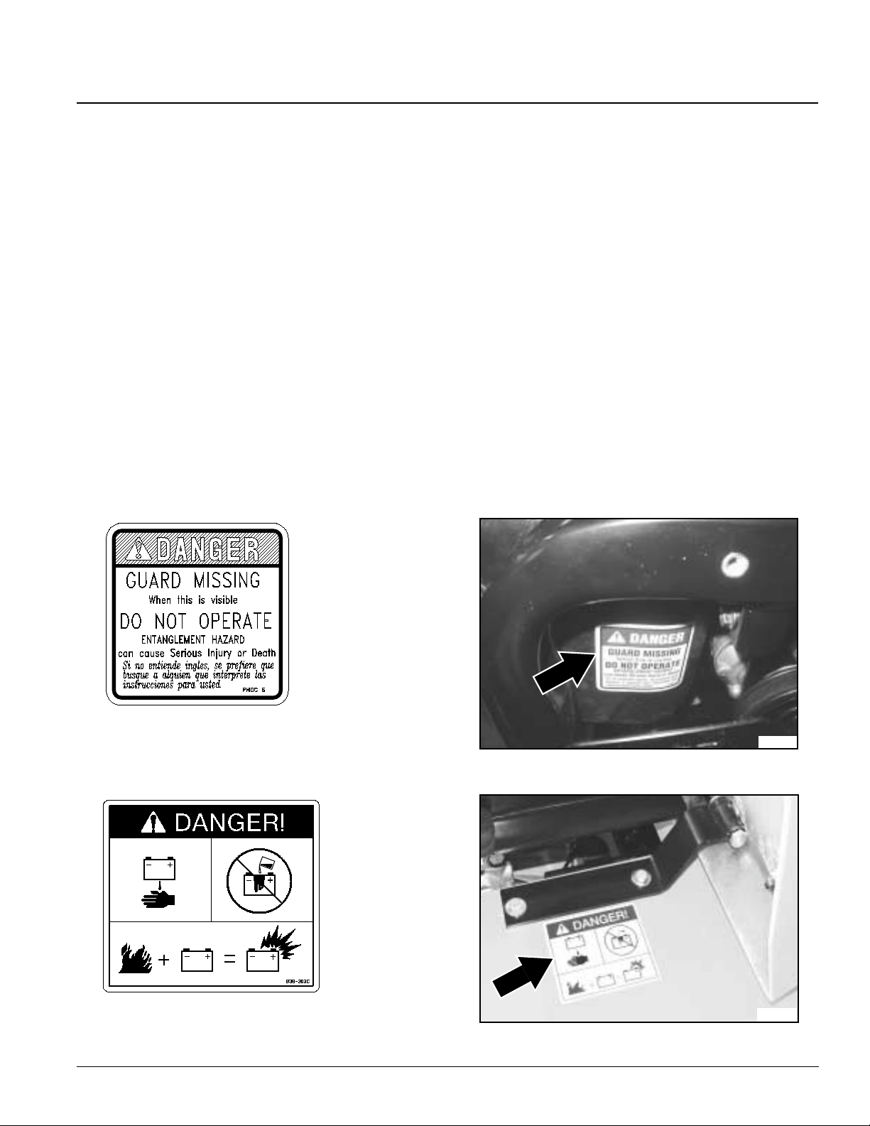
Table of Contents
Section 2 Important Safety Information
▲ Do not smoke or use electrical devices including cell
phones while refueling.
▲ Always check wheel lug nut torque values two hours after
initial operation and two hours after each tire repair and/
or replacement. Routinely check lug nut torque valves
every 100 hours of operation. See "Wheel Lug Nuts" on
page 24.
▲ Support this vehicle securely before working beneath.
Chock wheels to prevent vehicle from rolling.
▲ Do not inspect hydraulic leaks with bare hands. Always
use an object such as a stick to inspect for leaks. Serve
injury can occur from pressurized oil breaking through
skin.
▲ Do not operate the vehicle with hydraulic leaks, frayed or
kinked hoses. Repair or replace hydraulic leaks and
damaged hoses immediately.
Safety Decals
1. Your Gondo Heavy Duty Utility Vehicle comes equipped
with all safety decals in place. They were designed to help
you safely operate this vehicle and to serve as a reminder to
keep safety uppermost in your mind. Read and follow decal
directions.
2. Keep all safety decals clean and legible.
3. Replace all damaged or missing decals. Order new safety
decals through your Land Pride dealer.
4. Some newequipmentinstalledduringrepairrequiressafety
labels to be affixed to the replaced component as specified
by Land Pride. When ordering new parts or components,
also request corresponding safety decals.
5. Refer to this section for proper label placement. Install new
decals as follows
a. Clean the area on which the decal is to be placed.
b. Spray soapy water on the surface where the decal is to
be placed.
c. Peel backing from decal. Press firmly on surface,
being careful not to cause air bubbles under decal.
d. Squeeze out air bubbles with the edge of a credit card.
818-543C
Danger: Guard Missing
838-303C
Danger: Battery
7/01/05
21434
21435
4400EX Heavy Duty Off Road Utility Vehicle 720-132M
7
Page 10
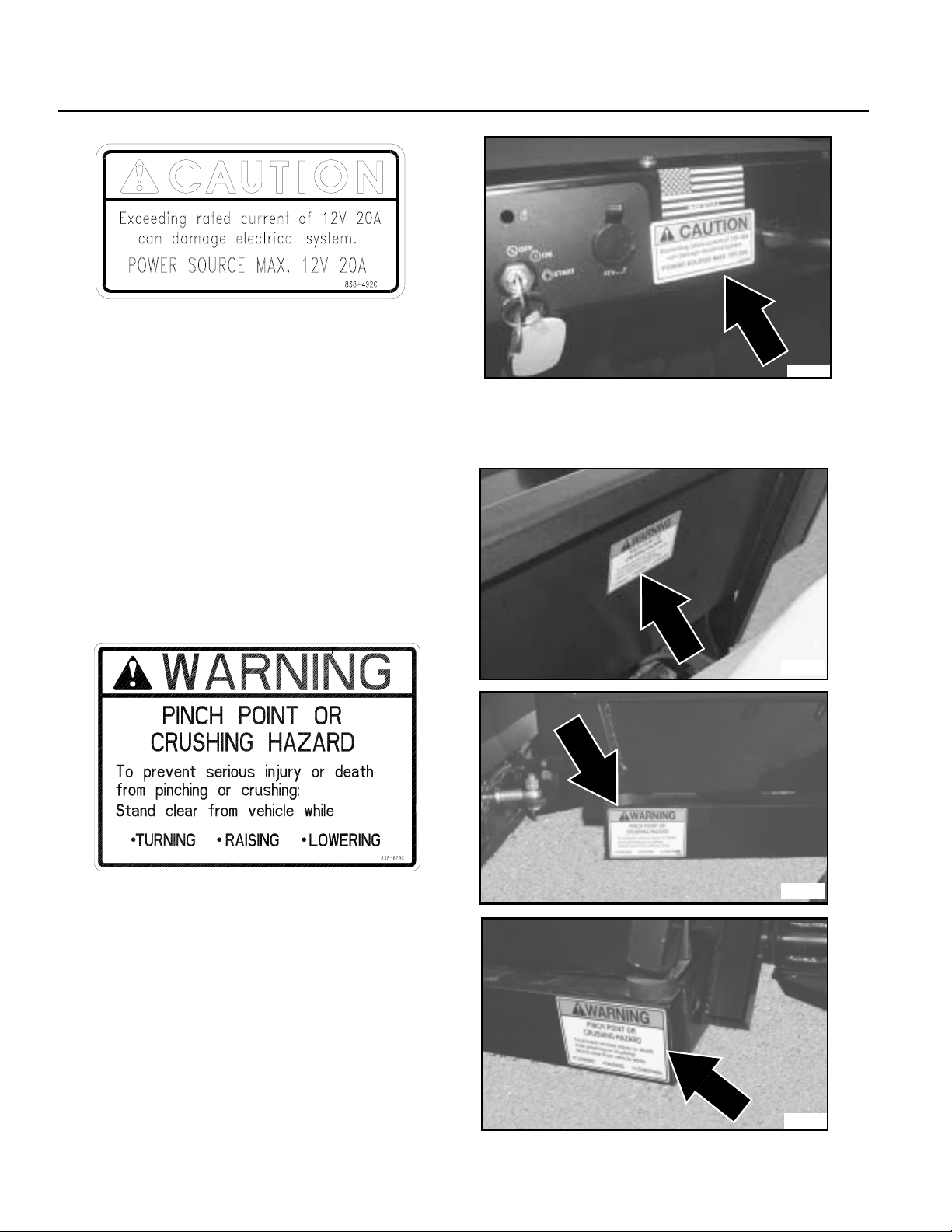
Table of Contents
Section 2 Important Safety Information
838-492C
Caution: Maximum PowerSource
21440
838-629C
Warning: Pinch Point or Crushing Hazard
21443a21458
21443a21443a
4400EX Heavy Duty Off Road Utility Vehicle 720-132M
8
21443b
7/01/05
Page 11
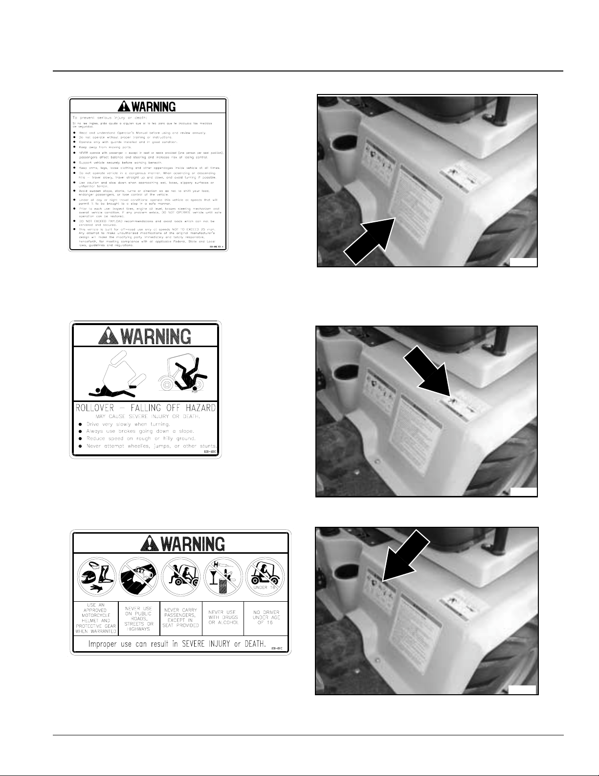
Table of Contents
Section 2 Important Safety Information
838-486C
Warning: General Utility Vehicle
838-489C
Warning: Rollover Hazard
21439
21439
838-491C
Warning: Improper Use
7/01/05
21439
4400EX Heavy Duty Off Road Utility Vehicle 720-132M
9
Page 12
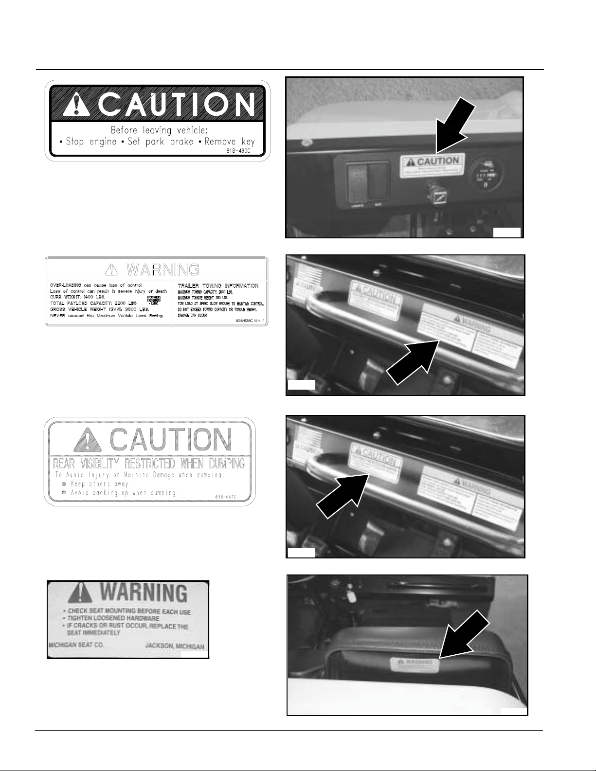
Table of Contents
Section 2 Important Safety Information
838-490C
Caution: Stop Engine
21438
838-628C
Warning: Load Rating and
Trailer Towing Information
838-667C
Caution: Rear Visibility Restricted
When dumping
22063
22063
20971
Warning Label Included with Seat
Warning: Check Seat mounting
4400EX Heavy Duty Off Road Utility Vehicle 720-132M
10
21345
7/01/05
Page 13
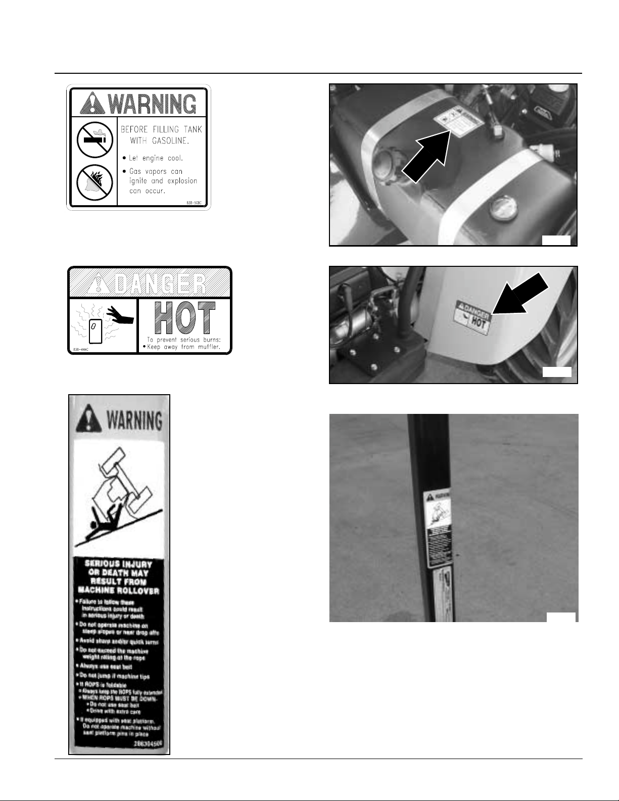
Table of Contents
Section 2 Important Safety Information
838-508C
Warning: Before Filling Tankwith Gasoline
22080
838-444C
Danger: Muffler hot
21436
838-688C
Warning:
Machine Rollover
22445
Location: Right Hand Inside ROPS post
7/01/05
4400EX Heavy Duty Off Road Utility Vehicle 720-132M
11
Page 14

Table of Contents
Section 3 Pre-Delivery and Check List
Section 3Pre-Delivery and Check List
Each vehicle must undergo a Pre-Delivery Inspection by the Dealer. Listed below is an example of the checklist that is
included with the Warranty Registration that isto be submitted to Land Pride upon Retail Sale. The Pre-Delivery
Certificate and Warranty Registration must be submitted to Land Pride in order to activate the vehicle warranty.
Pre-Delivery Certificate
The dealer is required to complete Land Pride’s
“Certificate of Heavy Duty Utility Vehicle Pre-Delivery”
form before customer maytakepossession of the vehicle.
Theinformationmustbefilled in and check list checked off
or initialed by individuals performing the checks.
Dealership’s name, signatures of individuals filling in the
form, seller’s signature, customer’s signature and signing
datesarealsorequiredbeforetheformisreturned to Land
Pride. Below is a list of the information found in the form
that is required to be completed and checked off.
Vehicle Information
Model No. _________________
Date _________________
Serial No. _________________
Engine Serial No. _________________
Dealer Service and Inspection List
___Fully charge battery. Check battery voltage to verify
that it is fully charged.
___Check tire pressure to make sure front tires have 15
psi and rear tires have 20 psi.
___Make sure wheellug bolts/nuts are tightened to 90
Newton meters/(65ft. lbs.).
___Check master cylinder to make sure it is filled.
___Checkengineoillevelat thedipstick.AddSAE10W30
oil if oil is below the full mark on thedipstick.
___Check engine for correct RPM. Set to factory
specification if needed. (See page 42)
___Check steering cylinder for tightness.
___Check choke control. It should move and return freely.
___Step on foot brake to make sure there isplenty of
pedal and that brakes hold pressure and do not bleed
off. Add brake fluid and bleed brakes if required.
___Make sure seats and seat belts are properly fastened
to the frame if so equipped.
___Make sure allsafety decals are in place.
___Check headlights tomake sure they are working and
are properly mounted.
___Inspect air cleaner element. Make certain it is clean
and in place.
___Inspect the fuel tank to make sure it is properly
installed and that there are no leaks.
___Check fuel level to make sure there is at least 1/8 of a
tank of gas prior to performing initial starting
operations.
___Inspect fuel lines to make sure they are properly
installed and that there are no leaks.
___Check steering by executing a full lock to lock turn in
each direction.
___Checkparkbraketo make sure it will engage,holdand
release.
___Make sure neutralstart feature is working by
depressing the clutch to start the unit.
___Check throttle control to make sure it moves and
returns freely.
___Check differential oil level at the differential oil plug.
Add 80/90 gear lube if oil is belowoil plug outlet.
___Checkoverallappearanceforcleanlinessandforbody
and molding damage.
Dealer Test Ride List
___Check engine for starting, accelerating, running and
idling smoothly.
___Check steering response. There shouldbe no free-
play.
___Checkforward,neutral and reverseshifting response.
Also check neutral start response by depressing the
clutch to start the vehicle.
___Check park brake to make sure it engages, holds and
disengages.
___Make sure rocker switches are all working.
___Make sure throttle is responsive and returns freely.
___Make sure suspension ride is satisfactory and stable.
___Make sure thereare no fuel or petroleum leaks.
___Make sure the foot brake has a firm engagement and
that stopping is straight.
___Make sure thereare no bad rattles or vibrations.
4400EX Heavy Duty Off Road Utility Vehicle 720-132M
12
7/01/05
Page 15

Table of Contents
Section 3 Pre-Delivery and Check List
Dealer Delivery To Customer List
___Warranty registration form is complete.
___Owner’s Manual has been delivered to and reviewed
by the customer.
___EngineManualhas been delivered to and reviewedby
the customer.
___Warranty Policy limits and requirements have been
explained to the customer.
___Customer has reviewed the safety video.
___Location and functions of vehicle controls have been
explained.
___Fuel transportation and storage procedures have
been explained.
___Fluid fill and lubrication points have been located and
explained to the customer.
___Customer has completed the driving course.
___Information on the safety decals have been reviewed
with the customer.
Customer Acceptance List
Customerinitialsrequiredwhere acceptedassuccessfully
completed.
___Customer has reviewed and understands Land Pride
warranty policy.
___Customer has inspected the vehicle and it meets
customer’s satisfaction.
___Customerunderstandstheimportanceoffollowingthe
owner’smanual instructions.
___Customer has completed the Land Pride safety
training course.
7/01/05
4400EX Heavy Duty Off Road Utility Vehicle 720-132M
13
Page 16

Section 4 Operating Instructions
Section 4 Operating Instructions
Operator Responsibilities
Table of Contents
!
WARNING
It is the operator’s responsibility to have read this manual
thoroughlyand to know how to operate this vehicle safely in all
situations. See "Section 2 Important Safety Information"
starting on page 3.
Pre-Start Check List
• Lubricate the vehicle as indicated in the Lubrication
portionof "Section 7 Lubrication and Fluids" on page
33.
• Check tire pressure as indicated in the "Tire Inflation
Chart" on page 25.
• Make sure wheel lugbolts/nuts are tightened to 65ft.lbs.
• All nuts, bolts, screws and fasteners should be checked.
Refer to the Torque Value Chart in "Section 13
Appendix" starting on page 48.
• Turn on headlights to make sure battery has a charge
and electrical lighting circuit is working.
• Step on the foot brake and hold down to make sure it
canbeappliedwith plenty of pedalmovementremaining
and that the brakes hold without loosing pressure. Add
brake fluid as indicated in "Brake Fluid" on page 37.
Bleed brakes if required.
• Check park brake to make sure it will engage, hold and
release.
• Check steering by executing a full lock to lock turn in
each direction.
• Check neutral start feature by depressingtheclutchand
starting the vehicle. (The vehicle should not start unless
the clutch is depressed.)
• Check engine oil level at the dipstick. Add oil as
indicated in "Engine Oil" on page 33 if oil is at or below
the add mark on the dipstick. Do not overfill or plug
fouling will occur.
• Check differential oillevel at the differential oilplug. Add
gear lub as indicated in "Differential Oil" on page 35 if
oil is below oil plug outlet.
• Check fuel level to make sure there is at least 1/8 of a
tankof gas prior to performing initial startingoperations.
• Allow engine to warms up for 15 minutes or more to
reach operating temperature before checking to make
sure engine idle speed is set at 1100 +/- 100 rpm and
that maximum engine static speed does not exceed
3800 rpm. Modifying or adjusting the carburetor to
increase vehicle speed above factory set
specificationis a safety violation and could result in
voiding the warranty.
General Operation
Starting the Engine
Followstarting procedures displayedatthe gearshift lever
and as noted below.
!
DANGER
Avoid injury or death from entanglement in the rotating
components and pinch points. All shields must be in place and
secure when operating. Keep all persons away from rotating
components and pinch points.
1. Set park brake.
2. Place gearshift in neutral. Depress clutch pedal.
Engine will not start with clutch pedal out.
3. Apply choke fully when engine is cold.
4. Turn ignition key fully clockwise and hold until engine
starts.
5. Release ignition key to run position and choke to
normal operating position immediately after engine
starts.
6. Turn ignition key counterclockwise to stop engine.
Operating a Gondo is like operating a car with a standard
transmission that has five speeds forward and one
reverse. The keyed 12 volt electronic ignition with clutch
depressed start feature makes for safe and easystarting.
Braking is accomplished by simply depressing the
automotive style brake pedal located on the floorboard.
This activates both front and rear automotive type
hydraulic drum brakes. Depress clutch and brake pedals
when coming to a complete stop. A lever action parking
brakeismountedonthefloor board between operator and
passenger seats. Push the lever forward to the horizontal
position to engage the park brake and pull back to the
vertical position to release.
Raise cargo box by pulling back and holding on the dump
lever. Push forward on the lever and hold to lower the
cargo box. Stop cargobox movement by releasing the
lever.
!
DANGER
Make sure area behind cargo box is clear of personnel before
operating the dump lever. Bodily harm can result from being
pinched between the cargo box and another object or from a
load dumping and/or rolling onto a bystander.
Dashboard Switches and Instruments
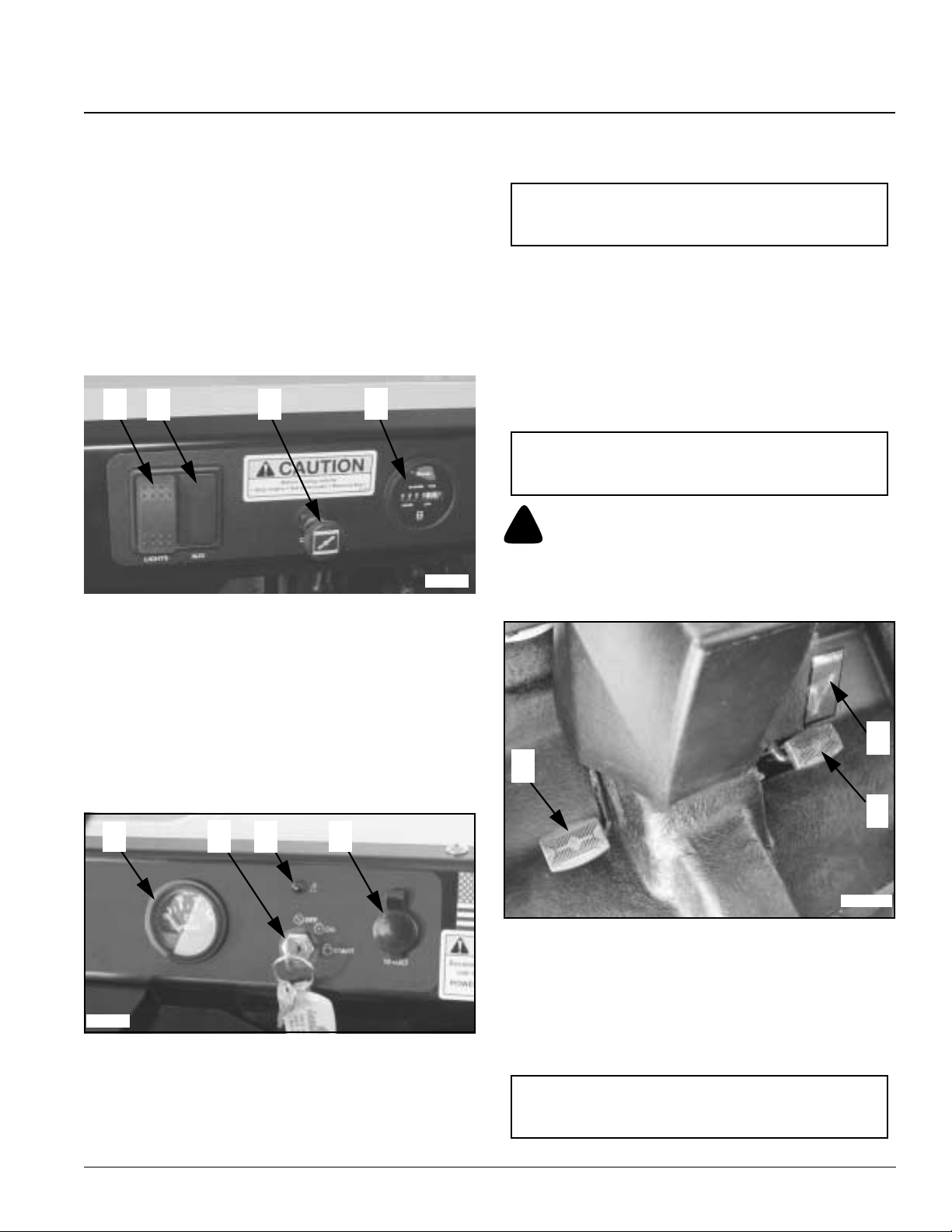
Refer to Figure 4-1A and Figure 4-1B on page 15
#1 Light Switch: Turns on two sealed beam head lights
when the switch key is on. Press top of light switch to
turn on lights and bottom of switch to turn off lights.
#2 Auxiliary Switch Slot: A 12 volt on/off accessory
switchmay be installed at this location to operate an
auxiliary accessory such as a power winch.
4400EX Heavy Duty Off Road Utility Vehicle 720-132M
14
7/01/05
Page 17
Section 4 Operating Instructions
Table of Contents
#3 Choke Switch: Used to increase fuel mixture to help
start the engine when it is cold. Pull chokeknob out
and hold to start a cold engine. Release knob after
engine has started. Do not choke an engine that is
hot from operating. Engine flooding may result. To
avoid running the battery down, allow a flooded
engine to set 15 to 30 minutes before attempting to
restart it. Hold theacceleratorpedal all the waydown
without applying the choke while starting a flooded
engine.
#4HourMeter:Indicatesnumberofhoursvehiclehasrun
to the nearest 1/10 of an hour.
1 2
3
Figure 4-1A
4
21438
the dipstick and oil light stays on after the engine is
running.
NOTE:It is normalfortheoillighttocomeonwhenthe
ignitionswitchis turnedonandstayonuntiltheengine
is running.
#8 Power Plug Outlet: 12 volt accessories such as a cell
phone or light can be connected to this outlet.
Foot Operated Controls
Refer to Figure 4-2
#9 Accelerator Pedal: Changes engine rpm andvehicle
ground speed. Press down on the accelerator pedal
with your foot to increase speed and let up onthe
pedal to decrease speed.
IMPORTANT: Vehicleshouldnotmoveonlevelground
while engine is idling and brakes are not applied. See
your nearest Land Pride dealer if vehicle mov es .
!
WARNING
Always release clutch pedal slowly when starting and changing
gears. Sudden release of the pedal can damage the power train
and jerk the vehicle injuring the operator and/or passenger.
#5 Volt Meter: Indicates battery is charging. Check
battery if volt meter registers a charge that is lower
than normal. See your authorized Land Pride dealer
if battery is good and volt meter still register low
charge.
#6 Ignition Switch: Starts and shuts off the engine.The
engine is off when the switch key is in its vertical
position. See "Starting the Engine" on page 14 for
correct starting procedures.
5
21342
#7 Oil Light: Indicates lowoilpressure if illuminated while
engine is running. Stop engine immediately if light is
on. Check oil level and add if low. See your
authorized Land Pride dealer if oil levelshows full on
6
7
Figure 4-1B
8
9
10
11
22063
Figure 4-2
#10 Clutch Pedal: Stops transfer of engine power to the
transmission without stopping the engine from
running. Always change gears while holding the
clutchpedaldown.The clutch and brakemustalways
be applied when bringing the vehicle to a complete
stop. See #11, Brake Pedal for stopping the vehicle.
IMPORTANT: Always press clutch pedal fully down.
Resting your foot on clutch pedal can cause clutch
plates to slip and shorten their life.
7/01/05
4400EX Heavy Duty Off Road Utility Vehicle 720-132M
15
Page 18
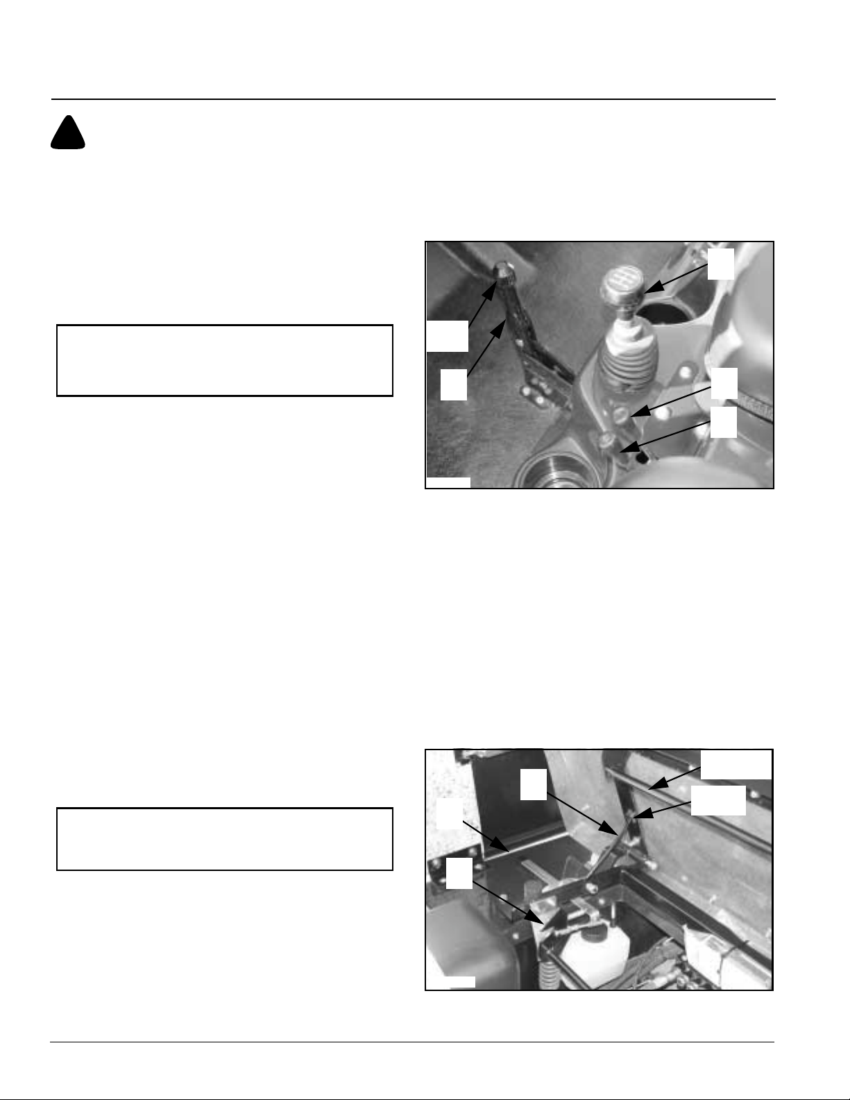
Table of Contents
Section 4 Operating Instructions
!
DANGER
Sudden hard braking pressure can throw occupants forward
causing body injury and death. Whenever possible, apply
pressure to the brake pedal gently and increase presser slowly
until desired braking force is achieved.
#11 BrakePedal:Slowsvehiclespeedquicklyand stops
vehicle.Slow vehicle speed quickly byremovingyour
foot from the acceleratorpedal and then apply
pressure to the brake pedal. Apply clutch and brake
pedal before coming to a complete stop.
gear only after reaching sufficient speed and engine
RPM. Continue shifting up to the next higher gear
until highest gear is reached. Shift downone or two
gears if loss of engine power is noticed.
Alwaysplacegearshift in first gear when descending
a steep grade under load to make use of the
additional braking force provided by the engine.
15
NOTE: Do not rest foot on brake pedal while driving
vehicleexceptwhenslowingorstopping. Pressure on
the brake pedal willshorten life expectancy of brake
liners.
Hand Operated Controls
Refer to Figure 4-3
#12 Park Brake Lever: The park brake lever is located
onthe floor board right of the operator and should be
set at all times the vehicle is not in operation.Push
the leverforward to the horizontal position to set the
brake.Releasethebrakebypullingbackon the lever
to the verticalposition. Do not drive vehiclewith park
brake on.
The knob on the end of the handle may be turned to
make minor adjustments to the braking capabilities.
Major adjustments should be made at either end of
the brake cable.
#13 Dump Lever: Dump lever activates the hydraulic
cylinder to raise and lower the cargo box. Pull lever
back to raise cargo box. Push lever forward to lower
cargo box.
#14 Auxiliary Lever: Auxiliary leveris used to operate a
hydraulic cylinder on a front mounted snowblade or
to operate equipment pulled by the Gondo.
Additional accessories must be purchased to make
hydraulic connections.
IMPORTANT: Release dump lever immediately when
cargo box is fully up or down to e xtend hydraulic seal
life and to prevent overheating.
#15 GearShift Lever: Changes transmission gears from
neutral to one of the five forward speeds or reverse.
Alwaysstart engine with gear shift in neutral. Follow
theshiftpatternontheshiftlevertofindyourselected
gear.
Always start in first gear when under load or on an
incline. You may start in second gear if on the level
withnoloadand no incline. Shift up to the next higher
Knob
12
22061
Figure 4-3
14
13
Engine Hood Release
Refer to Figure 4-4
#16 Hood Release Lever: The Hood release lever is
located under the driver seat on the left hand side.
Pull back on the lever and lift up on the engine hood.
#17 Hood Support Rod: Secures the engine hood in the
raisedpositionbyplacingthe hood supportrodin the
socket as shown.
#18 Hood Latch: Secures the hood in the lowered
position. Lift up on the hood and return the support
rod down to its stored position. Lower the hood until
the latch rod is secured by the hood latch (#18).
Latch Rod
17
16
18
22070
Figure 4-4
Socket
4400EX Heavy Duty Off Road Utility Vehicle 720-132M
16
7/01/05
Page 19
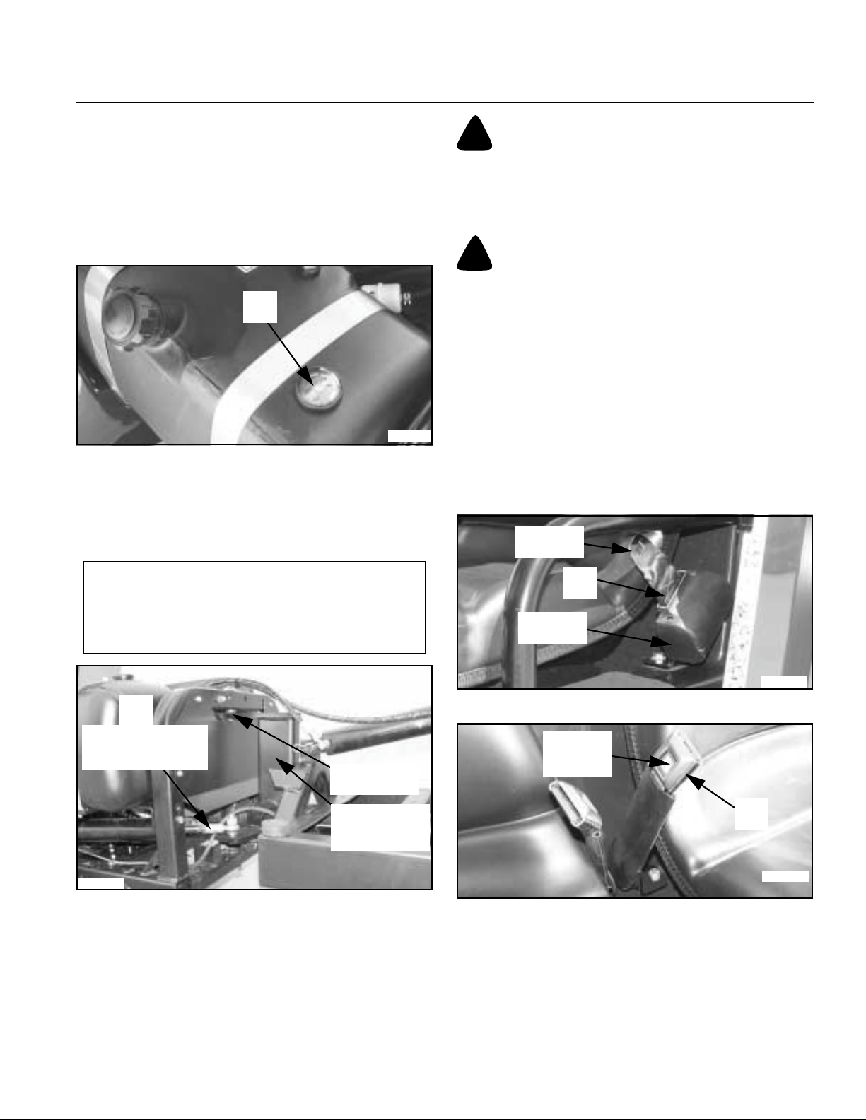
Table of Contents
Section 4 Operating Instructions
Fuel Indicator
Refer to Figure 4-5
#19Fuel Gauge: The fuel gauge,locatedon the gas tank,
displays approximately how much fuel you have in
thefuel tank. Alwayspark the vehicle on levelground
to get an accurate reading. The fuel tank is empty
whenthe fuel gauge needle points to E and full when
the needle points to F.
19
22080
Figure 4-5
Steering
Refer to Figure 4-6
#20PowerSteering: Thevehiclesteersbypivotingabout
the center swivel yoke with a hydraulic cylinder.
!
WARNING
Lap belts should fit snugly and as low around the hips as
possible. Wearing seat belts high around the waist greatly
increases the chances of that person being injured in a
dangerous situation.
!
WARNING
Never use a lap belt for more than one person and never buckle
the lap belt to a buckle designed to receive the other lap belt.
Seat Belt Components
Refer to Figure 4-7
#21 Lap Belt: The lap beltis the belt that extendsfromthe
retractor when pulled across your lap to be buckled.
It is located on the left side of the driver’s seat and
right side of the passenger’s seat.
Refer to Figure 4-8
#22 Buckle: Both operator and passenger buckles are
locatedbetweenthe two seats.It secures the lap belt
in place.
Tongue
IMPORTANT: Become familiar with the steering
capabilitiesof the Gondo beforeputtingthevehicleinto
service. Be certain to practice steering going forward
and backing up as it has a different feel than normal
front wheel steered vehicles.
20
Power Steering
Hydraulic Cylinder
Pivot Point
Center Swivel
Yoke
21346
Figure 4-6
Seat Belts
Gondos equipped with a ROPS (Roll Over Protection
System) are also equipped with seat belts.
Seat Belts with ROPS reduce the risk of injury from
rollovers,collisions andbeing thrown from the vehicle.Itis
the responsibility of the operator and passenger to decide
if their situation warrants using seat belts.
21
Retractor
22071
Figure 4-7
Release
Button
22
22072
Figure 4-8
Seat Belt Operation
Pull the lap belt across your hips and insert its tongue into
the buckle until you hear it snap. Release the lap belt by
pressing the release button in the center of the buckle.
Guide the lap belt to its original position as it retracts to
keep it aligned and to prevent its tongue from striking and
damaging surfaces on the vehicle.
7/01/05
4400EX Heavy Duty Off Road Utility Vehicle 720-132M
17
Page 20

Section 4 Operating Instructions
Table of Contents
Driving Conditions
Terrains vary creating different driving situations. The
following are circumstances you might encounter and
suggestions on how to operate the Gondo safely. Always
approach each new situation with extreme caution until
you have become experienced in handling your vehicle.
We recommend for your safety and the safety of others
that you allow only operatorsexperienced in driving a
standardtransmission,understand all potentialdangersof
operatingthisvehicle,has studiedthismanual,viewedthe
video safety tape suppliedwith this vehicle and has
received actual hands-on instructions from an
experienced operator.
Sandy Terrain
Tires with high air pressure perform better in loose sand.
Also,stayin low gear to avoidspinningthewheels.Always
maintainvehiclecontrol,don’tmakesharpturnsandavoid
hard braking when possible.
Muddy Terrain
Better traction is achieved by accelerating the vehicle
slowly to avoid spinning the wheels. Making sharp turns
and hard braking can cause the vehicle to skid out of
control. Let up on the accelerator pedal and stop when
skidding out of control.
Clean off mud residue stuckto rotating drive shafts and to
the tires as quickly as possible. Mud clinging to rotating
parts causes and imbalance that can damage vehicle
components.Alsocleanthebrakedrums of mud to reduce
premature brake wear.
Uneven Terrain
The Gondo’s center articulating steering enables the four
driving wheels to maintain contact in various uneven
terrainsituations.Becauseof this, the vehicleiscapableof
maneuvering over rough surfaces, up and down steep
inclines. Avoid operating on excessively steep hills and
especially on hills that are steeper than 15 degrees.
Climbing Steep Hills
Alwaysapproach a steep hill straight on in 1st(lowgear)to
reduce engine strain and minimize stalling. Continue
straightupthe hill in low gear moving rightorleftonly to go
around obstacles. Do not attempt to turn the vehicle
around during a steep climb.If the vehicle stalls or should
youdecide to stop the climb,place vehicle in reversegear
andbackdownthe hill slowly and as straight aspossibleto
a safe location. If needed, apply thebrakes very lightly to
assist slowing down vehicle’s descent. Hard braking can
cause total loss of control and a rollover situation. Don’t
depress the clutch while backing down except when
bringing the vehicle to a complete stop.
Maximum traction and control is achieved while traveling
upa steep incline in1st gear at the lowest possiblespeed.
Also traveling slowly allows more time to correct a
dangerous situation.
Descending Steep Hills
!
WARNING
Do not descend a steep hill with rear cargo box removed.
Dangerous forward weight distribution is created.
Watery Terrain
Always determine thedepth of water before driving
through it. Do not drive through water that is higher than
the bottom of the floor board. Always enter the water
slowly and continuetraveling slowly through the water to
minimizesplashing. The vehiclecould stall if the electrical
system gets wet. Never allow water to get up around the
engine.A wet engine is likelyto stall or become damaged.
Test the brakes for stopping capabilities once through the
water.Allow the brakestodry before proceeding if braking
capabilities are reduced. Brakes can be dried faster by
driving the vehicleslowlyon a levelsurfacewhileapplying
light pressure to the brake pedal.
Snowy and Icy Terrain
Like muddy terrain, accelerate the vehicle slowly to avoid
spinning the wheels. Avoid making sharp turns and hard
braking. Let up on the accelerator pedal and stop when
skidding out of control. Always maintain a steady slow
speed allowing time to slow down and stop. Remember
slicksurfacesrequiremore time to slow down, make turns
and stops.
4400EX Heavy Duty Off Road Utility Vehicle 720-132M
18
Descend most hills straight down in 1st gear. When
necessary, use steady pressure on the brakes without
locking them up. Hard braking can cause total loss of
control and a rollover situation.
Always consider ground conditions and load distributions
as outlined below before descending a steep hill:
• Is the ground surface wet or dry? Wet surfaces can
result in loss of control and should not be attempted.
• Is the ground surface firm or loose? Loose surfaces can
result in loss of control and should not be attempted.
• Is the terrain fairly even or is it eroded and uneven with
holes and boulders? Surfaces that are not fairly even
canresult in loss of controland should not beattempted.
• Can the descent be made fairly straight or will you be
required to turn to a degree that is approaching crosshill travel making the vehicle subject to imbalance and
turning over.
• Consider the vehicle’scenter of gravity. Is itfront heavy,
loaded high with cargo and is there a passenger along
adding weight over the front axle? The rear axle should
have sufficient weight over it to counter balance weight
distributedoverthefrontaxle.A vehicle with poor center
of gravity is subject to flipping forward end over end.
7/01/05
Page 21

Table of Contents
Section 4 Operating Instructions
Is the vehicle approaching maximum load rating
•
capacity. Is the vehicle total loaded weight approaching
maximum rated gross weight? Too much weight can
reduce operator’s ability to brake and control the
vehicle.
• Is the vehicle towing a trailer and if so is the trailer
carryingaloadapproachinggrossweightoftheGondo?
Again,toomuchtrailer weight can reduce the operator’s
ability to brake and control the vehicle.
Traverse Traveling on Steep Hills
Cross a steep slope only if no other alternative exists.
When crossing, consider ground conditions and load
distributions outlined in "Descending Steep Hills" on page
18. Make certain that the weighton the uphill side of the
vehicle is equal to or heavier than the weight on the
downhill side of the vehicle. Cross in 1st gear and if your
vehicle starts to tip over,turn the vehicle down hill quickly
to regain stability and control.
Pulling Loads
The Gondo is capable of pulling a load weighing many
times more than its own weight. Because of this it is
important thatyouknowthevehicle’scapabilityandhow to
operateitinawaythat willnotdamagethevehicleorinjure
yourself or others. Always consider the following:
• Does the load exceed the recommend towing capacity?
Too much weight will push the vehicle around and
hinder its stopping capabilities.
• Is the load front heavy placing too much weight on the
hitch?Excessive hitch weight will makethefront wheels
light on the ground causing you to loose steering and
traction capabilities.
• What type of terrain is the load being pulled over? Is the
groundsoft,wet,dry or inclined. Any of these can hinder
vehicle control. See "Descending Steep Hills" on page
18 when considering type of terrain.
When towing always start in 1st gear and shift to a higher
gear only if the vehicle has sufficientpower.Do not travel
ina gear that can not control the load. Heavy loads should
be towed in 1st or 2nd gear depending on their ability to
hold the load back from pushing the vehicle when letting
up on the accelerator pedal. Remember, the heavier the
load the longer it takes for the brakes to stop the vehicle.
Towing the Gondo
The Gondo should be loaded on a trailerfor towing.
However, it can be towed behind a tractor or another
vehicle for a short distance to retrieve it from an area
where a trailer won’t go.
IMPORTANT: Do not tow the Gondo at speeds over 5
mph. Higher speeds may result in loss of control and
damage to the Gondo, vehicle towing the Gondo and
personnel.
IMPORTANT: Owner assumes all responsibility and
liability resulting from towing the Gondo.
Towing Without a Trailer
Thefollowingprecautions shouldbefollowedwhen towing
the Gondo behind a tractor or another vehicle:
• Approved tow chain or rope mustbe securely attached
to the Gondo at a location that will not damage the
vehicle or come loose from the vehicle.
• The gear selector must be placed in neutral position.
• The park brake must be off.
• Someone must be steering the vehicle while it is being
towed for it to track properly.
• When possible, the engine should berunningtooperate
thepowersteering.Ifthe engine will not run,thesteering
will be very heavy and will eventually quit as oil is bled
from its steering sector.
• Do not tow the Gondo at speeds over 5 mph. Higher
speeds may result in loss of control and damage to the
Gondo, vehicle towing the Gondo and personnel.
• Do nottowanothertrailerorvehiclebehindaGondo that
is being towed.
• Do not tow the Gondo on roadways or across open
areas accessible with a trailer. Instead, load the vehicle
onto a trailer for towing.
Towing Loaded on a Trailer
The Gondo may be driven or winched onto a trailer. The
following precautions should be followed when loading
and towing the Gondo on a trailer:
• Always make certain loading ramps are capable of
supporting the Gondo’s weight, properly spaced for the
Gondo wheels and secured to the trailer before loading
the Gondo.
• Two peopleshouldbepresentwhenloadingthevehicle.
One stands clear of the Gondo as he guides the vehicle
up the ramps and onto the trailer. The other sits in the
Gondo and steers the vehicle as it is being loaded.
• Drive or winch vehicle onto the trailer slowly to prevent
accidents.
• Once loaded, turn the switch key off, set park brake and
place transmission in 1st gear.
• Properly secure thevehicle at its fourcorners to the four
corners of the trailer with tie down chains or other
approved tie downs. Tie downs must be designed to
withstand forces induced into them during acceleration,
making turns and applying brakes.
• Always tow at a speed where the driver is in control of
his vehicle at all times.
• Always allow enough traveling distance to slow down
and stop. The Gondo’s added weight to the trailer will
require additional time and distance to slow down.
• Slow down when turning to prevent loss of control and
rollovers.
7/01/05
4400EX Heavy Duty Off Road Utility Vehicle 720-132M
19
Page 22

Section 4 Operating Instructions
Table of Contents
Do not allow anyone to ride in the Gondo while towing it
•
on a trailer.
• Obey all state and local laws for towing.
Traveling Tips From the Trail Masters
At Land Pride we want you to get maximum working and
recreational enjoyment out ofyour utility vehicle whether
you are usingone of our All-Terrain Runabouts or one of
our terrain hugging Gondo utility trucks. If your work
projectorrecreationaladventureis going to takeyouonan
extended ride deep into the wilderness or way out on the
prairie, you’ll need toseriously consider some of the
following tips from experienced pros about safety, gear,
clothing, supplies and driving techniques.
Preparation and Planning
Do a complete equipment check as follows:
1. Make sure you have plenty of fuel and oil to make the
trip and then some.
2. Make sure your tires have proper inflation, your lug
bolts are tight and that you have a spare and the tools
to change, repair and inflate a tire. Consider adding a
puncture sealant to your tires as a preventative
measure.
3. Check for any loose or missing parts and definitely
makethose needed repairs before going anywhere.It
is especially important that you check steering,
braking, throttle, electrical and engine components
thoroughly.
Plan Your Route
1. Plan your route, destination and rendezvous points
before starting out.
2. Don’t go it alone if at all possible. Taking someone
elsealongreducesthepotentialforloss of lifeormajor
injury to inclement weather, animal attacks, or
accidents. Besides, it’s more fun when you have
someone to share the adventure with.
3. Obtain trail or area maps of your travel routes to and
from your destination. Communicate yourtravelplans
to responsible friends and or proper authorities. Plan
rendezvous points at conspicuous landmarks along
yourroutejustincaseyourunintounexpectedtrouble
on the trail.
4. Make sure you take a weather radio and two-way
communication devices such as cellphones or long
range-two way radios. It is also good to have ground
flares, a flare gun, a smoke canister, emergency
strobe light, a reflecting mirror, matches for a signal
fire and a compass.
Plan Your Gear
1. Check the short and long range weather forecast and
take protective gear and clothing to cover all
contingencies. It doesn’t have to snowfor you to fall
victim to hypothermia or exposure. Take or wear
appropriate eye and head protection, gloves, boots, a
long sleeve shirt, long pants,a jacket, rain gear, dry
socks and afull change of dry clothing.
2. Plan your gear and gear up for the best and worst of
environmental conditions.
3. Packa first aid kit, sunblocker, lip balm, water, insect
repellent, personal medications, tarp or tent, flash
light, survival knife, binoculars, camera, tool kit, rope,
duct tape, tow strap, winch or come-along, eating,
utensils, cooking utensils and high energy trail food.
4. Tie and lash down your gear and supplies securely.
Keepthe bulk of the weight centered and mounted as
low as possible on the vehicle in order to maintain a
lowcenter of gravityforsafeand stable off-road travel.
Going Out on the Trail
1. Take it all in when hitting the trail but do it safely!
2. Make sure you brief your passenger on proper safety
procedures like keeping hands, arms, feet and other
bodily appendages inside the vehicle. Passengers
shouldonly be transportedinfactory supplied seating.
3. Operator and passenger are responsible for deciding
if their situation warrants using Seat Belts.
4. Avoidoperating on excessively steep hills and
especially on hills that are steeper than 15 degrees.
Avoidcrossing slopes if possible and don’t make
sharp uphill steering corrections or a rollover could
result. If your vehicle starts to tip over on a slope turn
the front wheels quickly down hill to regain stability
andcontrol.The best waytoclimbmost hills is to drive
straight up while maintaining a steady ground speed
and constant engine rpm. The best way to descend
mosthillsisstraightdownwhile using steady pressure
on the brakes without locking them up. Locking up the
brakes in a steepdownhill situation can result in loss
oftraction,steering and control. When you must cross
a slope on soft terrain, keep the front wheels turned
slightly uphill and maintain a constant speed and a
straight line of travel.
5. Driving too fast, being inattentive and turning too
sharplyonslipperysurfacescanresultin rolloversand
accidents almost quicker than any other ground
condition we know of. Snow cover, wet trails, loose
graveland frozen ground can all contribute to this
dangerous condition. In these conditions maintain
sharpfocusonthetrailahead. Don’t make sharp turns
and avoid the need for hard braking if at all possible.
Slow down and stopIf you do start to slide.
4400EX Heavy Duty Off Road Utility Vehicle 720-132M
20
7/01/05
Page 23

Section 4 Operating Instructions
Table of Contents
6. Avoidpaved surfaces. Land Pride vehicles are
designed exclusively for off-road use only.We
understand that occasionally operators have to cross
publicroads or right of ways to gain access to work or
recreationsites,butdon’tgetinthewayof fastertraffic
and cross quickly and safely.
7. The Gondo is capable of crossing intermittent
streams where the depth of the water briefly comes
intocontactwiththebottomofthefloorboards,butyou
must keep these considerationsin mind; You must
know how deep thewater is and the strength of the
current. Cross where you have a gradual incline for
entry and exit and the bottomis fairly clean and free of
obstacles. Maintain a slow steady speed disturbing
the stream bed as little as possible. If you submerge
the engine, you will lose forward momentum and
power. If you submerge the engine or the whole
vehicle,donotattempttostart the vehiclebuttakeit to
your nearest dealerimmediately. After intermittent
stream or shallow water crossings, dry out the brake
linings by slightly accelerating the engine rpm while
riding the brakes momentarily until full drive power
and braking are restored.
8. Backing up inan off-road situation might seem a
simplethingtodotoanovice,buthavingto back down
a hill is a very dangerous situation. If you are on level
ground always look behind you and back up slowly. If
you find yourself having to back down a hill, apply the
brakes very lightly. Hard braking can cause total loss
of control and a rollover situation. Try to back straight
down the hill without turning. Turning in this situation
can also cause a rollover.
9. Wheneverpossible, park your vehicle on a level
surface with the transmissionin gear, set the park
brakeand remove the key. If you do have to park on a
hillside make to sure chock the rear wheels on the
downhill side to prevent a roll away. It’s a good idea to
keep your spare key stashed separately.
10. Never operate a vehicle under the influence of drugs
or alcohol. When you’re driving off-road vehicles you
need to keep your senses keen and capable of quick
reaction, sharp perception and good balance.
11. Workingorrecreation in the deep wilderness or on the
prairies can be personally rewarding and very
enjoyable to those who truly love and understand
nature and the outdoors. Good judgement, maturity,
proper preparation and planning can turn these
adventuresinto great experiencesyou’ll talk about for
a lifetime. Share these adventures with young people
wheneveryou can and show them how to do it
properly. Don’t let anyone under 16 operate this
vehicle. They just aren’t mature and experienced
enough to take on the serious responsibility of
operating a vehicle in the off-road environment
without the benefit of an experienced adult with them.
Remember, the only one who can prevent and avoid
an accident is the operator in control and that’s you!
7/01/05
4400EX Heavy Duty Off Road Utility Vehicle 720-132M
21
Page 24
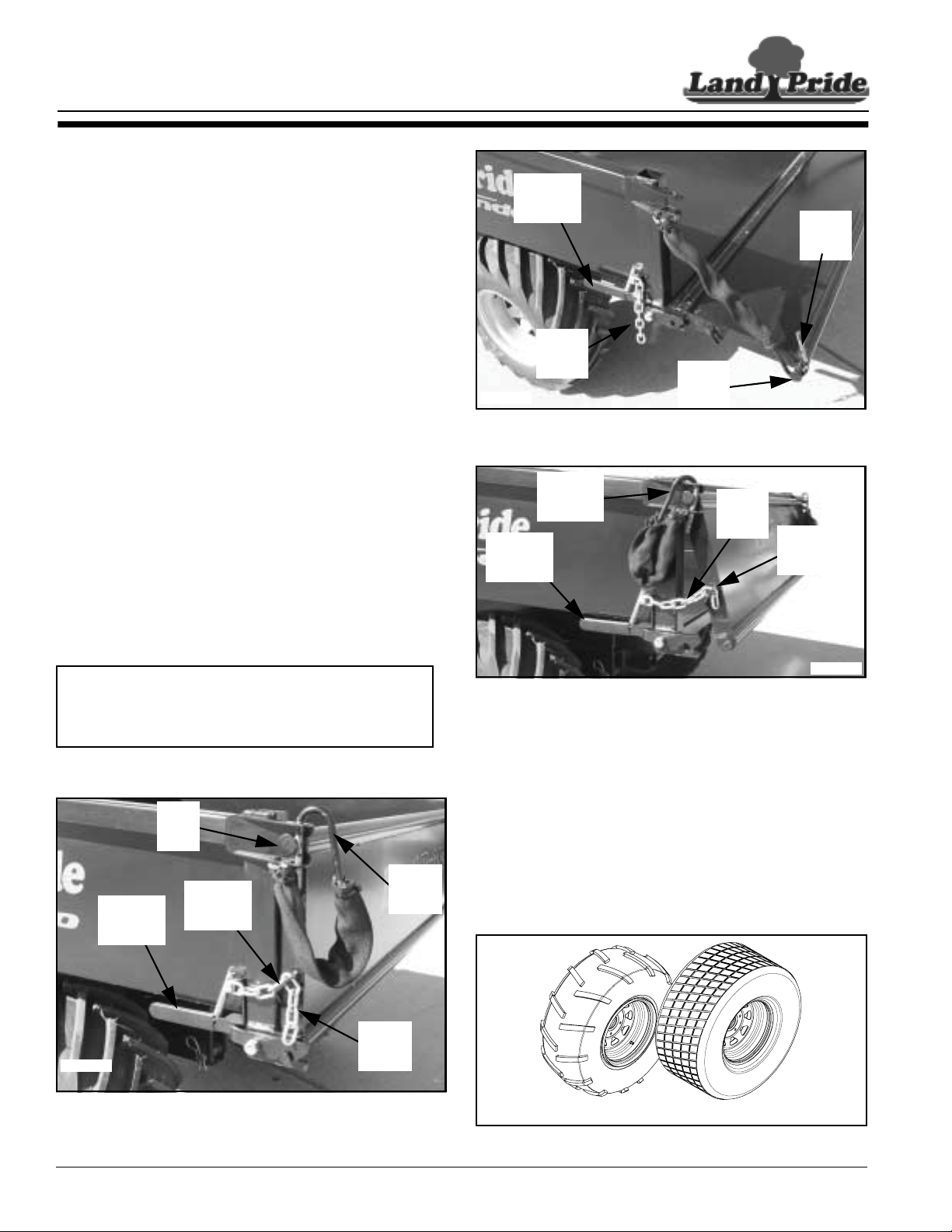
Table of Contents
Section 5 Options and Accessories
Section 5 Options and Accessories
Gondo Options
There are several options Land Pride offers when
selecting your Gondo.
Dump Bed Option
There are two styles of dump beds availableforyour Land
Pride Gondo.
• Gondola style dump bed without tailgate. (See top cover
photo #22081)
• Cargo style dump bed with tailgate. (See bottom cover
photo #22076 and Figure 5-3)
Tailgate Operation (Cargo box option only)
Thetailgateonthecargoboxis designed to hinge from the
top down and from the bottom out depending upon
whether one is loading and unloading cargo or if one is
spreading bulk material over an area.
• Hinging from the top down: (Refer to Figure 5-1)
Unhook the catch chains and gate hooks on both sides
to swing the tailgate completely down. Catch the gate
hooks on the tailgate pins, Figure 5-2, to support the
gate parallel with the bed.
• Hinging from the bottom out: (Refer to Figure 5-3)
Secure the gate hooks at the top and set the catch
chains in the notched brackets at the desired opening
length. Press down on the tailgate release lever to open
the gate. Drive forward while raising the cargo box to
discharge bulk material out the back. See note below.
NOTE: Do not raise cargo box any higher than
necessary while discharging bulk material out the
back.Raisingcargoboxtoo high will cause materialto
spill over the tailgate.
Gate
Pin
Gate
Release
Lever
Notched
Bracket
Hook
Release
Lever
Gate
Hook
Catch
Chain
22074
Tailgate Opened From The Top
Figure 5-2
Gate
Hook
Release
Lever
Tailgate Opened From The Bottom
Figure 5-3
Gate
Pin
Catch
Chain
Notched
Bracket
22075
Tires
Refer to figure 5-4
There are two types of tires available for your Land Pride
Gondo.See figure 5-4. Both are 4-ply rated. The Bar Tire
withitschevronbarsisa good tire to choose when traction
is your first priority.This tire is a tough tire for going over
rough terrain. The Turf Tire is a good selection when one
wants to preserve the terrain being traveled over. Golf
courses, parks and other maintained areas make the Turf
Tire an excellent choice.
22073
Tailgate Secured Shut
Figure 5-1
4400EX Heavy Duty Off Road Utility Vehicle 720-132M
22
Catch
Chain
Bar Tire
figure 5-4
Turf Tire
21387
7/01/05
Page 25

Table of Contents
Section 5 Options and Accessories
Gondo Accessories
A variety of accessory equipment has been designed to
complement your needs and make your Land Pride
Gondo a very functional and useful vehicle. See your
nearest Land Pride Dealer for all accessories available.
Accessories available are:
• Grab light
• Rear receiver type hitch
• Hydraulic bed lift
• Certified ROPS with seat belts (if not originally equipped
with ROPS)
• Cab enclosure with soft doors and windshield wiper
• Front snow blade
• Log skidder
• Cold weather engine kit (Prevents carburetor icing)
• 12 Volt Ceramic Heater
7/01/05
4400EX Heavy Duty Off Road Utility Vehicle 720-132M
23
Page 26
Table of Contents
Section 6 Maintenance
Section 6 Maintenance
General Maintenance
!
WARNING
Read and observe all safety warnings in this manual and in the
engine service manual.
!
WARNING
Except when checking or changing components, always keep
protective shields on for safety as well as for cleanliness.
!
WARNING
Keep engine clean of oil, grease, trash and debris which can
cause engine overheating, fires and belt wear. Clean only after
the engine has completely cooled. Weargloves to protect hands
from cuts, puncture wounds and burns.
!
WARNING
DO NOT have engine running when servicing or making
adjustments to the vehicle. Shut engine off, place transmission
in gear, set park brake and remove ignition switch key for
maximum safety.
!
DANGER
Repairs or maintenance specifically requiring engine power
should be performed by trained personnel only. Transmission
gearshouldbesetinneutralwithtiresproperly chockedor with
drive tires properly supported off the floor. Enclosed areas
should be properly ventilated to prevent carbon monoxide
poisoning.
Some repairs require the assistance of a trained service
mechanic and should not be attempted by unskilled
personnel. Consult your Land Pride dealer when
assistance is needed.
Prepare V ehicle for Maintenance
Before servicing the vehicle the following procedure must
be followed to secure the vehicle:
1. Park vehicle on a level surface. Don’t work under or
around a vehicle parked on a steep incline.
2. Place gear selector in 1st or reverse.
3. Set park brake.
4. Turn ignition switch off and remove switch key.
5. Block pinch pointarea at the center swivel yoke to
preventmovement. (See DANGER below.)
6. Chock front andback side of the wheels not being
raised off the ground whenever jacking a vehicle or
when ground surface slopes.
7. Always use jack stands to support the vehicle when
working under the vehicle.
!
DANGER
Pivoting about the center swivel yoke must be blocked to
prevent movement before working on or around the vehicle.
This articulation area is an extremely dangerous pinch point
area caused by just a slight turning of the steering wheel even
when the vehicle is not running.
Torque Values
!
DANGER
Exercise extreme caution when working with and around the
driveshaft and power steering belt. Make certain the engine
cannot be accidentally started. Shut engine off and remove
ignitionswitchkeyformaximumsafety.Repairsor maintenance
requiring engine power should be performed by trained
personnel only.
Regular maintenance is the best prevention for costly
downtime or expensive, premature repair. The following
pages contain suggested maintenance information and
schedules which the operator should follow on a routine
basis.
Remainalert for unusualnoises, they could be signaling a
problem. Visually inspect the vehicle for any abnormal
wearor damage. A good time to detect potential problems
is while performing scheduled maintenance service.
Correcting the problem as quickly as possible is the best
insurance.
4400EX Heavy Duty Off Road Utility Vehicle 720-132M
24
Wheel Lug Nuts
!
WARNING
Particular attention must be given to tightening the wheel lug
nuts. Failure to correctly torque these items may result in the
loss of a wheel, which can cause personal injury and damage to
the vehicle.
Torque Values
FT -lbs. Nm
Wheel lug nuts 65 - 75 88.14 - 101.7
Always check wheel lug nut torque values two hours after
initial operation and two hours after each tire repair and/or
replacement
100 hours of operation. See "Maintenance Schedule" on
page 32.
. Routinely check lug nut torque valves every
7/01/05
Page 27
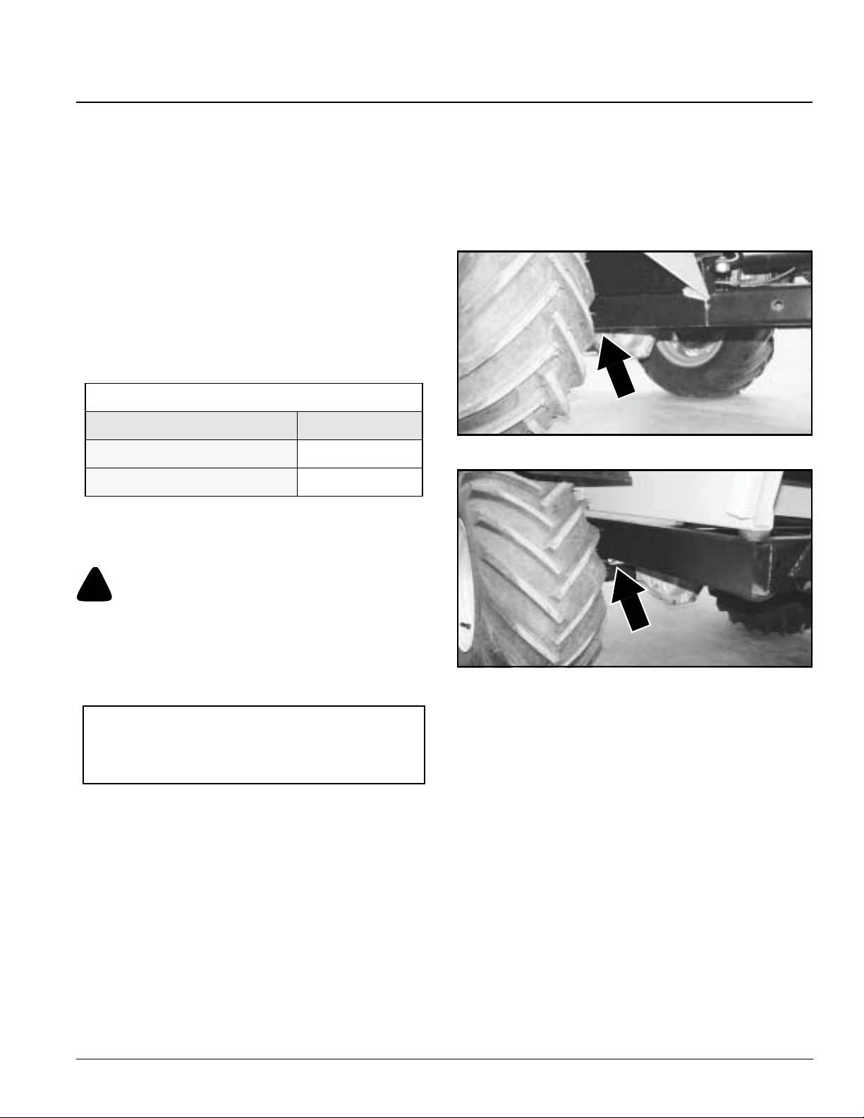
Section 6 Maintenance
Table of Contents
Engine Torques
For engine torque values, see engine owner’s manual.
All Other Torques
For all other torques refer to “Torque Values Chart”
page 48.
Tire Maintenance
Use only tires recommended by Land Pride.
It is important for your safety and the safety of others that
the tires have correct air pressure.Check air pressure in
all four tires before each use.Visually inspect tires for loss
of air throughout each day of operation. See Tire Inflation
Chart below for correct tire pressure.
Tire Inflation Chart
Tire Inflation PSI
Front Tires
Rear Tires
15*
20*
*Maximum tire pressure is noted on tire side wall.
6. Work may now be performed on the vehicle. Be sure
to properly torque all bolts that were loosened. Wheel
bolts should be torqued after the vehicle is lowered to
the ground.
7. Lower the vehicle by first jacking the vehicle up high
enough to remove the jack stands. Then carefully
lower the jack until the vehicle is on the ground.
8. Remove wheel chocks.
.
21350
Figure 6-1
Jacking the Vehicle
!
DANGER
For your safety and safety of others, a jacked vehicle must be
supported properly with jack stands before working under and
around it. Also the wheels on the ground must be chocked on
both sides to prevent the vehicle from rolling forward or
backward.
IMPORTANT: Use a hydraulic jack, floor jack, or
scissor type jackto lift vehicle.Do not use a handyman
jackor bumper jack and don’t jack against the bumper,
body, differential case, axles or hydraulic lines.
1. Prepare vehicle for maintenance as outlined in steps
1-6 on page 24.
2. Loosen the lug nuts on a wheel being removed
approximately1/2turncounterclockwisewhileitisstill
on the ground.
3. See important note above. Place proper jack under
vehicle as follows:
a. Front tires: Refer to Figure 6-1. Place jack under
the main frame just behind the axle.
b. Rear tires: Refer to Figure6-2. Place jack under
the main frame just in front of the axle.
4. Jack vehicle only high enough to do the work
intended.
5. Support vehicle securely with jack stands before
working under and around the vehicle.
21351
Figure 6-2
Seat Belts
Refer to Figure 4-7 and Figure 4-8 on page 17
Periodicallycheck the seat belt webbing, retractor,buckle
and mounting hardware for wear and damage.Always
check seat beltsfor wear and damage after a collision.
Replace a damaged seat belt with genuine Land Pride
parts before putting the vehicle back into service.
Occasionally the seat belt webbing can become twisted,
tangled or jammed. Free seat belt webbing before putting
the vehicle into service using the following procedures:
1. Pullthe lap belt allthe wayout of the retractor.Untwist
the belt and remove any objects that are jamming the
belt.
2. Hand feed the lapbelt into the retractor. If the belt
does not fully retract, pull it out and retractuntil it is
completed retracted.
3. Once the belt has retracted, pull it fully out again and
feed it back into the retractorseveral more times to
make sure itis working properly.
7/01/05
4400EX Heavy Duty Off Road Utility Vehicle 720-132M
25
Page 28

Table of Contents
Section 6 Maintenance
Electrical System
A 12 volt, 25 amp, negative ground electrical systemis
provided. The electrical system is protected bya fuse
located behind the dash near the key switch and a
moisture proof self-resetting circuit breaker in the wiring
harness near the starter at the engine. The amp ratings
are as follows:
• Fuse behind the dash - 30 Amps
• Self-resetting circuit breaker - 30 Amps
Common circuit failures can be from “shorts”, corroded or
dirty terminals, loose connections, defective wire
insulation or broken wires. Switches, solenoids and
ignitioncomponentscanalsonotfunction,causing a short
or open circuit.
Before attempting any fault diagnosis of the electrical
system, use a test light or voltmeter to check the battery
voltage. If the battery voltage is satisfactory, check the
cleanliness and tightness of the terminals and ground
connections. A generalunderstanding of electrical
servicing and useof basic test equipment is necessaryfor
troubleshooting and repair.
Major overhaul or repair of the starting motor or alternator
should be performed by trained technicians only.
Battery
The battery is located in the engine compartment. It may
be either a maintenance-free sealed battery or a
maintenance-free battery with removable vent caps.
Inspect your battery and know which battery your have.
Water can not be added to sealed batteries as the vent
caps are not removable.
!
WARNING
Acid can cause serious injury to skin and eyes. Avoid skin
contact with battery acid and always wear eye protection when
checking the battery. Flush area with clean water and call a
physician immediately. Acid will also damage clothing.
!
WARNING
Sparks can cause a battery gas explosion which will result in
personalinjury.Keepbattery terminalsfromtouchinganymetal
parts when removing or installing the battery. Do not allow
metaltoolstoshortbetween battery terminals and metal vehicle
parts.
!
WARNING
Do not allow an open flame near the battery when charging.
Hydrogen gas forms inside the battery. This gas is both toxic
and flammable and may cause an explosion if exposed to a
flame.
Checkwaterlevelonceayear.The waterlevelineach cell
should be up to the level indicator. If not, add water.
Distilledwatershouldbe used to fill each cell in thebattery.
However,tapwater may be used if tap water is not hard or
does not have high mineral or alkali content. Do not
overfill. Have the charging system checked by your local
Land Pride dealer if the battery requires water every few
months.
Land Pride recommends a maintenance-free battery size
BCI group U1/U1R. The battery should also have a
minimum of 300 cold cranking AMP’s and 375cranking
AMP’s at 32oF. Always follow the manufacturer’s
maintenance, safety,storing and charging specifications.
!
CAUTION
Do not overfill battery with water. Electrolytes may overflow
and damage paint, wiring or structure. Use soap and water to
clean the battery. Be careful not to get soap and water into the
battery. Use baking soda mixed in water to clean corrosion off
the terminals.
!
WARNING
Incorrect battery cable connections can damage vehicle’s
electrical system and cause battery cables to spark. Sparks
around a battery can result in a battery gas explosion and
personal injury.
• Always disconnect negative (black) battery cable before
disconnecting positive (red) cable.
• Always reconnect positive (red) battery cable to the
positive(+)post before reconnectingnegative(black)cable
to the negative (-) post.
4400EX Heavy Duty Off Road Utility Vehicle 720-132M
26
Jump Starting the Battery
Refer to Figure 6-3
The battery will discharge if the lights or any other
electricalequipmentisleftonaftertheenginehasstopped
running. Also, the battery will discharge if the lights or
power plug outlet is used over a prolong period while the
engine is idling.
The engine can be jump-started with a booster battery.
Follow procedures listed below when jump-starting.
Prepare Vehicle to Jump-Start
1. Use only a 12-volt battery to jump-start the ATR.
Higher voltages can damage the starter motor and
other electrical components. Do not use a 24 volt
battery or two 12-volt batteries connected in series.
2. Do not disconnect the vehicle’s battery that needs a
jump-start. Disconnecting thebattery can damage the
vehicle’s electrical system.
7/01/05
Page 29
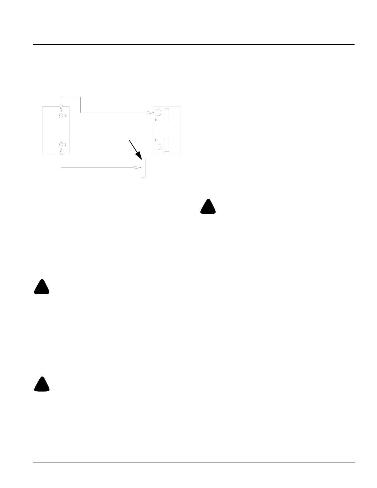
Section 6 Maintenance
Table of Contents
3. Park the live vehicle close to the vehicle needing a
boost without touching the two vehicles together. Set
parking brake on both vehicles.
4. Turn off all ignition switches, electric switches, light
switches and set parking brakes on both vehicles.
Red Jumper Cable
12 volt
Booster
Battery
Metal Surface
Black Jumper Cable
Figure 6-3
Dead
Battery
Connecting Jumper Cables
Refer to Figure 6-3
1. Inspect battery terminals for corrosion. Remove
excess corrosion before connecting jumper cables.
2. Connect one end of the red jumper cable to the
positive (+) terminal on the dead battery.
3. Connect the other end of the red jumper cable to the
positive (+) terminal on the booster battery.
4. Connect one end of the black jumper cable to the
negative (-) terminal on the booster battery.
!
WARNING
Make connection in step 5 below to a metal surface away from
the battery. Never connect to the negative (-) post of the dead
battery or to a metal surface near the battery.Sparkingnearthe
battery can result in a battery gas explosion and personal
injury.
5. Connect the other end of the black jumper cable to a
metalsurfaceonthevehiclethathasthedead battery.
Inspect jumper cables to make certain they are not in
thewayofmovingorrotatingcomponents.Reposition
any cables that will be in the way.
!
DANGER
Make certain everyone is clear of all moving and rotating
components before starting either vehicle.
6. Start the livevehicleandrunitatamoderatespeedfor
a few minutes to charge the dead battery.
7. After waiting a few minutes, start the dead vehicle. It
shouldstart withinseveraltries.Ifthevehicledoesnot
start, then theproblemmight be something other than
the battery.
Disconnecting Jumper Cables
Refer to Figure 6-3
1. Let both vehiclesrun forseveralminutesto charge up
the dead battery before removing the jumper cables.
2. Disconnect the black jumper cable from the metal
surface on the vehicle that had the dead battery.
3. Disconnect the other end of the black jumper cable
from the negative post on the booster battery.
4. Disconnect the red jumper cable from the positive (+)
post on the booster battery.
5. Disconnectthe other end of the red jumper cable from
the positive (+) post on the dead battery.
6. Drive the vehicle that had the dead battery for a while
to recharge the battery or recharge the battery with a
battery charger.Followall battery charger instructions
when recharging a battery with a battery charger.
Fuel System
!
DANGER
• Observe usual fuel handling precautions.
• Do not smoke while handling fuel.
• Keep fuel away from an open flame or spark.
• Refuel outdoors preferably, or in a well ventilated area.
• Allow engine to cool before servicing the fuel system.
• Donot fill tank with engine running or while engine is hot.
Allowtheenginetocoolbeforefilling. Spilling fuel overthe
engine, muffler, or a hot object may result in a fire or
explosion.
• Clean up any gasoline spills immediately.
• Store the vehicle away from open flame or spark if there is
fuel in the tank.
• Use extra caution when handling gasoline and other fuels.
They are flammable and vapors are explosive. A fire or
explosion from gasoline can burn you and others and can
damage property.
• Neverattempt to start engine when there is a strong odor of
gasoline fumes present. Locate and correct cause.
• Store gasoline in an approved container and keep it out of
children’s reach.
• Never buy more than a 30 day supply of gasoline.
• Do not fill gasoline containers inside a vehicle, on a truck,
or on a trailer. Interior carpets and plastic truck bed liners
insulate the container and slow loss of static charge.
• Whenpractical, remove equipment fromthe truck or trailer
and refuel the equipment with its wheels on the ground. If
thisisnot possible,thenrefuel theequipmenton the truckor
trailer using a portable container and not a gasoline
dispenser nozzle. If a gasoline dispenser nozzle must be
used, keep the nozzle in contact with the rim of the fuel tank
or container opening at all times until fueling is complete.
• Gasoline is a poison harmful or fatal if swallowed.
7/01/05
4400EX Heavy Duty Off Road Utility Vehicle 720-132M
27
Page 30
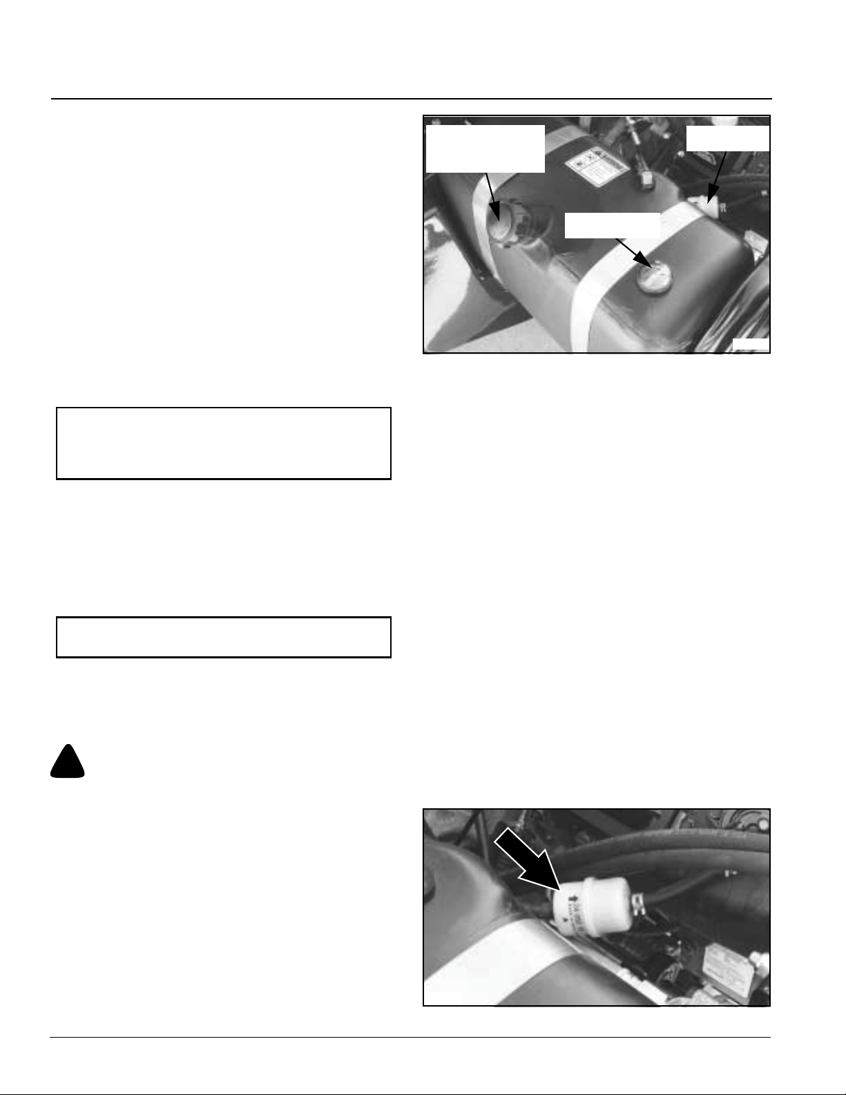
Table of Contents
Section 6 Maintenance
• Long-termexposuretovaporscancauseserious injury and
illness.
• Avoid prolonged breathing of vapors.
• Keep face away from nozzle and gas tank opening.
• Keep gas away from eyes and skin.
Filling the Fuel Tank
Refer to Figure 6-4
The fuel tank is located on the left side under the seat
console. Total fuel capacity is 8 gallons.
When filling the fuel tank, place gear shift in 1st or reverse
gear, set park brake, turn off engine and remove ignition
key. Tilt seat console forward to access fuel tank. Clean
dirt from around fuel cap, remove cap and begin filling.
When finished, screw cap back on securely and wipe up
any spilled gasoline.Use regular unleaded gasoline with
an octane rating of 87 or higher.
IMPORTANT: Never use methanol, gasoline
containing methanol and/or gasohol containing more
than 10% ethanol. These fuels can damage the
vehicle’s fuel system. Do not mix oil with gasoline.
Using a fuel stabilizer/conditioner in the vehicle can
provide benefits such as:
1. Keeps gasoline fresh during storage of 90 days or
less. The fuel tank should be emptied for longer
storage.
2. Cleans the engine during operation.
3. Eliminates gum-like varnish build-up in the fuel system.
IMPORTANT: Do not use fuel additives containing
methanol or ethanol.
Addthe correct amountof gas stabilizer/conditioner tothe
gas. Follow the gas stabilizer/conditioner manufacturer’s
directions for best results.
Emptying the Fuel Tank
!
DANGER
Never siphon a fuel tank by sucking on a hose with your mouth.
Gasoline is a poison. Also fuel vapors and gas are harmful to
your lungs and can permanently damage them. Always use a
siphon pump.
Fuel Cap and
Fuel Fill Opening
Fuel Gauge
Figure 6-4
Fuel Filter
22080
Fuel Filter and Fuel Line Maintenance
Refer to Figure 6-5
The fuel filter (Land Pride Part No. 831-031C) is installed
in the fuel line between the fuel tank and engine and
should be replaced annually. At the same time check the
fuellinehosesforanycracksor leaks.Inspectandreplace
fuel filter and fuel lines as follows:
1. Prepare vehicle for maintenance as outlined in steps
1-6 on page 24.
2. Safely secure the seat console in the raised position.
3. Following all Fuel Safety Cautions and Warnings,
removeclamps securingthefuelfilterandremovefuel
filter for inspection.
4. Checkfuelfilter forsediment and water accumulation.
Check fuel linesfor cracks and leaks.
5. Replace damaged fuel lines with new ones.
6. Replace fuel filter when sediment or water is present.
7. Reattach fuel filter to fuel line with arrowon the filter
pointing in the same direction fuel flows in the line.
Fuel flows towards the engine.
8. Install hose clamps around fuel filter.
9. Start vehicle and inspect for fuel leaks along fuel line
and fuel filter.
10. Shut off vehicle and remove wheel chocks if used.
The fuel tank will need emptying when preparing for long
term storage or replacing a damaged one.
1. Prepare vehicle for maintenance as outlined in steps
1-6 on page 24.
2. Follow all Fuel Safety Cautions, Warnings and
Dangers.
3. Remove fuel cap and siphon fuel through the fuel fill
opening with a siphon pump into an approved gas
container. Make sure the container is capable of
holding all the gas. Do not dump fuel on the ground.
4400EX Heavy Duty Off Road Utility Vehicle 720-132M
28
22079
Figure 6-5
7/01/05
Page 31
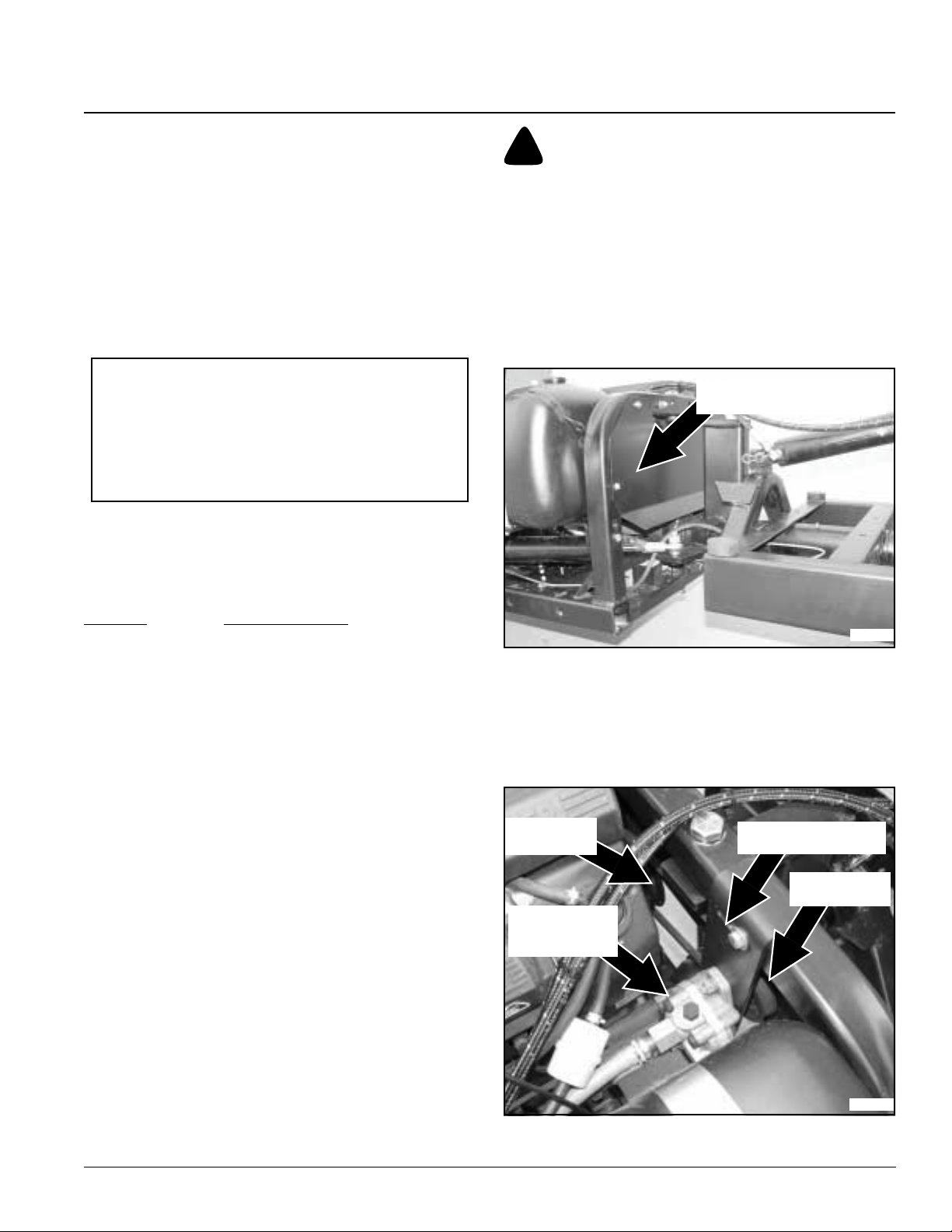
Table of Contents
Section 6 Maintenance
Engine Maintenance
General Information
Detailed instructions and recommendations for break-in
and regular maintenance are specified in the engine
operator’s manual. Engine warranty is backed by the
engine manufacturer. Please refer to engine
manufacturer’smanualforengine servicing, lubricating oil
levels, oil quality and viscosity recommendations, bolt
torques,etc.Specialattention should be paidtoapplicable
data that is not duplicated here.
High Altitude Carburetor Kit
IMPORTANT: The air-fuel mixture in carburetors
modified for high elevation is too lean when operating
at elevations below 5,000 feet. Operating engines with
modified carburetors below 5,000 feet can result in
engine overheating and serious engine damage.
Return carburetor to original factory specifications
when operating at low elevations.
!
CAUTION
Make certain to keep fingers from getting caught between belt
and pulley when rotating belt over pulley.
Replace power steering belt as follows:
1. Prepare vehicle for maintenance as outlined in steps
1-6 on page 24.
2. Safely secure the seatconsole in the raised position.
3. Disconnect negative battery cable.
4. Safely secure cargo box and seat console in the up
position to prevent injury.
Power Steering Shield
Gondo vehicles shipped from the factory are equipped
with carburetors designed to operate efficiently between
0 and 4,999 feet. Carburetor change over kits for different
altitudes may be purchased from your nearest Land Pride
Dealer. The following kits are available:
Elevation Carburetor Kit No.
0’ - 7,999’ Engine Standard
8,000’ & up 24755125-S
Po wer Steering Belt
Refer to Figure 6-6 & Figure 6-7
Power steering belt and pump are positioned behind the
engine and are protected by a shield. Do not remove
shield except to service the belt and always replace
shield after servicing the belt.
Replace power steering belt when it shows signs of
severe cuts, tears, excessive weather checking and
cracking or burns caused by slipping. Slight raveling of
belt covering does not indicate failure. Trim ravelings with
a sharp knife.
Inspect belt pulley grooves and flanges for wear. A new
belt, or one in good condition, should never run against
bottom of pulley groove. Replace pulley when this is the
case, otherwise belt will lose power and slip excessively.
Never pry a belt to get it on a pulley as this will cut or
damage the fibers of the belt covering.
Keep oil and grease away from belts and never use belt
dressings.Anyofthesewilldestroythebeltcompositionin
a very short time.
21346
Figure 6-6
Refer to Figure 6-6
5. Remove bolts securing belt cover and remove cover.
Refer to Figure 6-7
6. Loosen belt take-up bolt and hand squeeze belt
together. This should allow room to remove the belt.
Drive Pulley
Power Steering
Pump
Take-up Bolt & Slot
Driven Pulley
21353
7/01/05
Figure 6-7
4400EX Heavy Duty Off Road Utility Vehicle 720-132M
29
Page 32
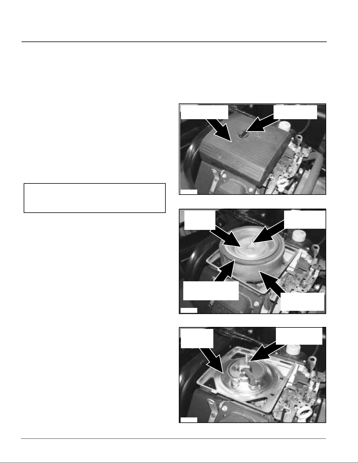
Section 6 Maintenance
Table of Contents
7. Remove belt by rolling it off over the drivepulley and
then lifting it up off the driven pulley.
8. Reinstall new belt by placing it over the drivenpulley
and then rolling it over the drive pulley.
9. Re-tension power steering belt and tighten take-up
bolt.
10. Reinstall belt cover and fasteners.
11. Reconnect battery negative cable.
12. Remove blocks securing cargo box up and lower
cargo box.
Engine Air Filter
Refer to Figure 6-8
A specially designed high density paper filter element
surrounded by an oil filled foam precleaner filter element
cleans the air supplied to the engine. Protect your engine
byordering only genuine Land Pride partswhenreplacing
the air filter elements.
NOTE:Do not operateenginewithadamagedairfilter
or without the air filter elements installed. Dirt will
enter the engine and cause a dust ingested engine
failure.
Air Filter Maintenance Schedule
• Check air filter daily before starting engine for dirt and
debri buildup. Also check daily for loose and damaged
filter components. Tighten loose components and
replace damaged components.
• Service precleaner foam element ever 25 hours of
operation. Service more often when operating in
extremely dusty or dirty conditions.
• Service paper element every 100 hours of operation.
Service more often when operating in extremely dusty
or dirty conditions.
Air Filter Replacement Parts
Order genuine Land Pride parts when replacing the
precleaner element.
Description Part No.
Precleaner Element (61 mm deep) . . . . 24-083-02-S
Paper Element (65 mm deep). . . . . . . . .47-083-03-S
Precleaner Foam Element
Refer to Figure 6-8 and Figure 6-9
1. Prepare vehicle for maintenance as outlined in steps
1-6 on page 24.
2. Safely secure the seat console in the raised position.
3. Loosen air cleaner cover knob and remove cover.
4. Remove outside precleaner element from the paper
element.
5. Wash precleaner element with warm water and
detergent. Rinse thoroughly to remove all traces of
detergent. Do not wring precleaner. Squeeze
excess water out and allow time toair dry.
6. Saturate precleaner with new engine oil and gently
squeeze all excess oil out.
7. Inspectprecleaner element forholesand tears before
reinstalling it. Replace element if damaged.
8. Reinstall precleaner element over the paper element
being careful not to damage the elements.
9. Reinstall air cleaner cover and secure with cover
retaining knob.
Air Cleaner Cover
21368
Figure 6-8
Element
Cover
Paper Element
Air Cover Knob
Element Cover
Wing Nut
Behind Precleaner
PrecleanerFoam
21369
Figure 6-9
Air Cleaner
Base
21370
Figure 6-10
Element
Rubber Seal On
Air Cleaner Stud
4400EX Heavy Duty Off Road Utility Vehicle 720-132M
30
7/01/05
Page 33
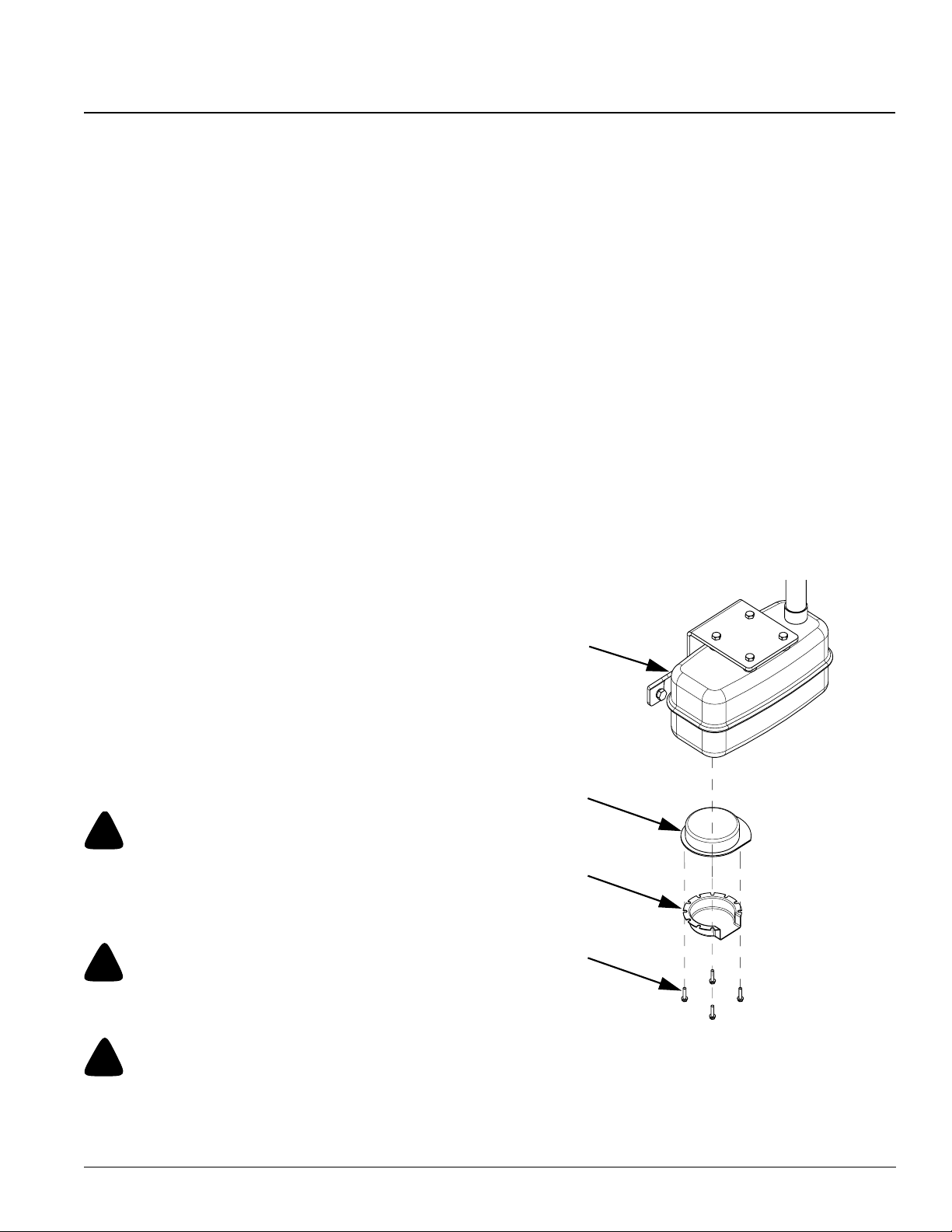
Section 6 Maintenance
Table of Contents
Paper Element
Refer to Figure 6-8, Figure 6-9 and Figure 6-10
1. Prepare vehicle for maintenance as outlined in steps
1-6 on page 24.
2. Safely secure the seatconsole in the raised position.
3. Loosen air cleaner cover knob and remove cover.
4. Removeelement cover nut, element cover and paper
element with precleaner element.
5. Remove precleaner element from paperelement.
Service precleaner as described in Precleaner
Service Procedure.
6. Do not wash paper element or blow pressurized
air over and through it. This will damage the
element. Always handle the element, new or used,
carefully to prevent damaging it. Inspect and replace
the element if it is dirty, bent ordamaged with a
genuineLand Pride element. Do not use an element
if its sealing surfaces are bent or damaged.
7. Check air cleanerbase. Make sure it is not bent or
damaged and is secured.
8. Check element cover.Make sure it is not bent or
damage and that it fits properly. Replace all damaged
air cleaner components.
9. Inspecttheaircleanerbaseforloosedirt or debristhat
mayhavefallenon it when the element was removed.
Be careful that none of the dirt drops into the intake
throat, remove base and wipeit clean.
10. Check the condition of the rubber seal on the air
cleaner stud, replace it if its condition is questionable
in any way. A new rubber seal is providedwith the
replacement paper element in a sealed packaged.
11. Reinstall paper element, precleaner, element cover,
element cover nut, and air cleanercover.Secure
cover with cover retaining knob.
Refer to Figure 6-11
The spark arrester is mounted inside the muffler behind
the muffler exhaust deflector. It is designed to suppress
sparks from escaping the muffler while they are still
glowing.
Spark Arrester Maintenance Schedule
• Inspect every 100 hours for carbon build-up and screen
damage.
• Clean whenever carbon build-up is visible or whenever
lost of engine power is detected.
• Replace when damaged.
Spark Arrester Maintenance Procedure
Refer to Figure 6-11
1. Remove spark arrester mounting screws, exhaust
deflector and spark arrester from the muffler.
2. Remove carbon deposits from spark arrester screen
witha wire bristle brush. Be careful not to damage the
spark arrester screen.
3. Inspect the spark arrester for holes or breaks in the
screen and replace if damaged.
4. Reattach spark arrester and exhaust deflector to
muffler with mounting screws.
Muffler
Spark Arrester
!
DANGER
The spark arrester does not stop all fire emitting sparks from
escapingthemuffler. Use extremecautionwhendrivingthrough
dry grass, brush and other fire hazard materials. Never stop or
park the vehicle over combustible materials.
!
WARNING
The muffler is very hot and will burn upon contact. Allow time
to cool before servicing the spark arrester.
!
CAUTION
Tomaintainefficiency,thespark arrester must beservicedevery
100 hours. Be careful not to damage the spark arrester screen
when cleaning.
7/01/05
Spark
Arrester
Exhaust
Deflector
Mounting
Screws
21349
Figure 6-11
Spark Arrester Replacement Parts
Description Part No.
Spark Arrester . . . . . . . . . . . . . . . . . . . . . . 840-174C
4400EX Heavy Duty Off Road Utility Vehicle 720-132M
31
Page 34
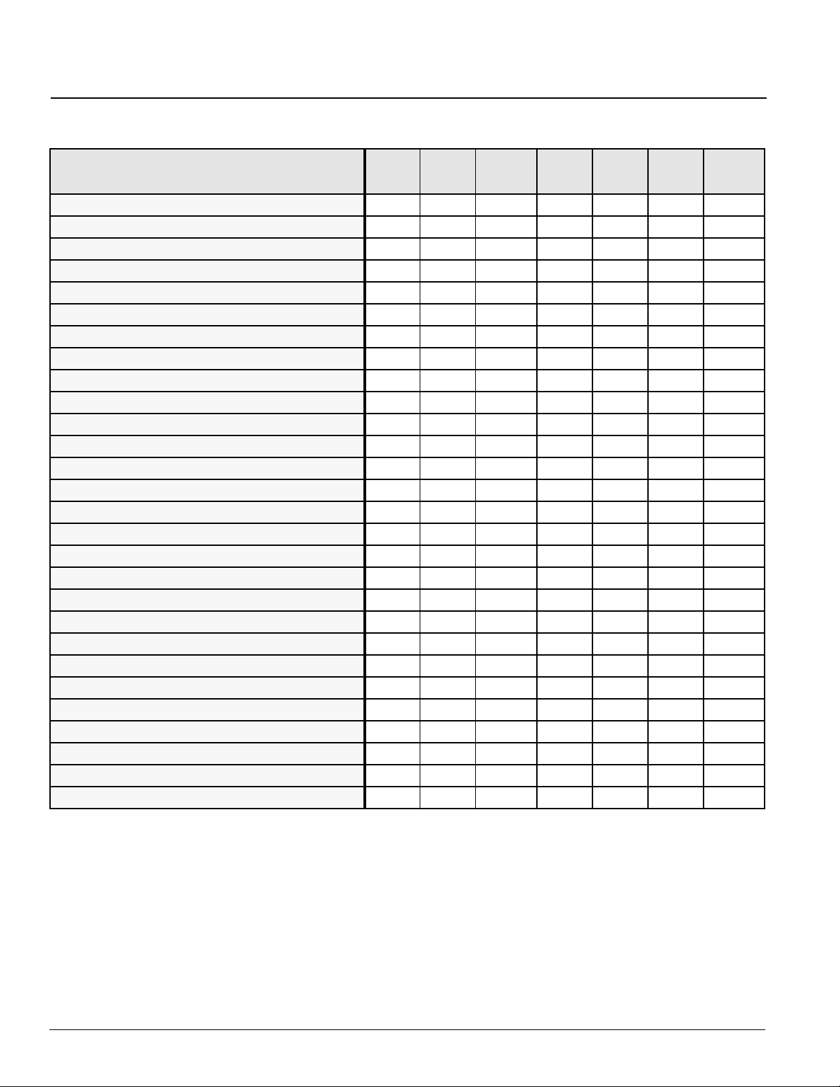
Section 6 Maintenance
Table of Contents
Maintenance Schedule
Maintenance Operation Daily
Check Engine Oil level X33
Check Hydraulic Fluid Level (1) X37
Check Tire Pressure X25
Check for Fluid Leaks X
Inspect All Nuts and Bolts for Tightness X24
Check and Clean Area Around Air Intake X30
Grease Zerk Fittings for rotating surfaces - 1 place X38
Service Air Cleaner Pre-cleaner Foam Element(2) X30
Check Wheel Lug Nuts (Torque 65 to 75 Ft. lbs.) (3) X24
Grease Zerk Fittings for bearings - 3 places X 38 & 38
Service Air cleaner Paper Element (4) X31
Change Engine Oil (5) & (6) XX 34
Change Engine Oil Filter (5) & (6) XX 34
Check Differential Fluid Level (7) XX 35
Check Transmission Fluid Level XX 36
Check Battery Charge and Water Level X26
Inspect Drum Brakes X
Inspect Parking Brake X
Check Master Cylinder Brake Fluid X37
Check & Regap Spark Plugs (1.02 mm / .04 in.) 200 hrs
Change Transmission Fluid Level 1000 hrs 36
Check Fuel Line Hoses and Clamps X28
Replace In-line Fuel Filter X28
Clean Battery and Terminals X26
Check Power Steering Belt X29
Clean Spark Arrester (8) X31
Service Bendix starter drive (9) X
Disassemble and clean solenoid shift starter (9) X
Every
25 Hrs
Every
100 Hrs.
Every
6 Mos.AsNoted
Every
Season
Refer to
Page
Reference Notes for above Maintenance Operation:
(1) Reservoir should be 3/4 full when all hydraulic accessories are in retract position.
(2) Replace air cleaner pre-cleaner if damaged.
(3) Check tightness after first 2 hours of initial operation and 2 hours after removal for repair and/or replacement.
(4) Replace paper element if extremely dirty or damaged.
(5) Make first engine oil and filter change after the first month of operation or at 20 hours of operation (whichever comes first).
(6) Service every 100 hours or 6 months (whichever comes first).
(7) Change differential oil ever year or every 400 hours (whichever comes first).
(8) Clean spark arrester whenever loss of engine power is noticed or every season (whichever comes first).
(9) Have a Land Pride dealer perform this service every year or every 500 hours (whichever comes first)
4400EX Heavy Duty Off Road Utility Vehicle 720-132M
32
7/01/05
Page 35
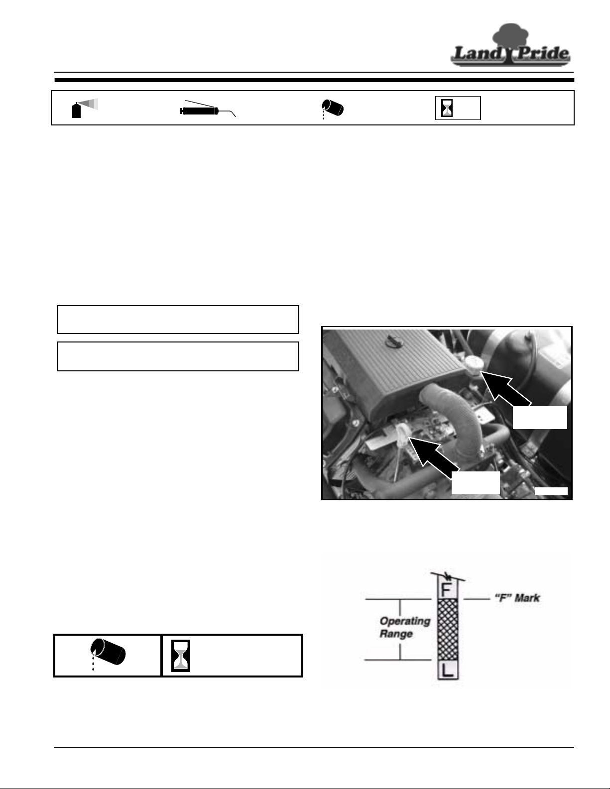
Section 7 Lubrication and Fluids
Section 7 Lubrication and Fluids
Table of Contents
Multi-purpose
spray lube
Multi-purpose
grease lube
Engine Oil
Engine lubrication is essential and must be maintained to
ensure long engine life. It is extremely importantto use
proper type and weight of oil in thecrankcase. It is also
extremely important to check oil daily and changeit
regularly as outlined in the maintenance schedule.
See Engine Operator’s Manual for a detailed description
of engine oil maintenance. Also the Engine Operator’s
Manualprovidesadditionalinformationnecessary to keep
the engine in top operating condition. Follow all
maintenance procedures provided in the Engine
Operator’sManual.
NOTE: Running engine low on oil can cause engine
damage and void engine warranty.
NOTE:Overfillingof oil levelcan cause loss of power,
engine damage and void engine warranty.
Engine Oil Maintenance Schedule
• Check oil level daily before starting engine.
• Make first oil change after the first month of operation or
at 20 hours of operation (whichever comes first).
• Make all subsequent oil changes every 6 months or
every 100 hours of operation (whichever comes first)
Multi-purpose
oil lube
50
Intervals at which
lubrication is required
2. Allow enough time for engine oil to settle before
checking oil level with dipstick.
3. Clean around the dipstick before removing it to keep
dirt and debris out of the engine.
4. Remove dipstick and wipe clean.
5. Fully insert dipstick and remove. Oil level on the
dipstick should beup to the “F” mark but not over.
6. If oil level on dipstick is low, remove filler cap located
on the top left valve cover and fill with recommended
oil. Repeat steps 2, 3, 4 and 5 until oil levelondipstick
indicates full. Do not overfill or plug fouling and
power loss will occur.
7. Replace filler cap and dipstick
Filler Cap
Engine Oil Type and Capacity
See also "Section 10 Specifications and Capacities" on
page 42
• Type of Lubrication based on temperature range
expected before next oil change:
0oF and up - SAE 10W-30
32oF and down - Synthetic SAE 5W-20 or 5W-30
• Service Class: SG, SH, SJ or higher
• Engine Oil Capacity:
2 US qts. / 1.9 liters with filterreplacement
or Fill to upper limit mark on dipstick.
Engine Oil Level Check
Refer to figure 7-1 and figure 7-2
Daily
Check engine oil with the dipstick daily asfollows:
1. Prepare vehicle for maintenance as outlined in steps
1-6 on page 24.
Dip Stick
figure 7-1
figure 7-2
22077
21372
7/01/05
4400EX Heavy Duty Off Road Utility Vehicle 720-132M
33
Page 36
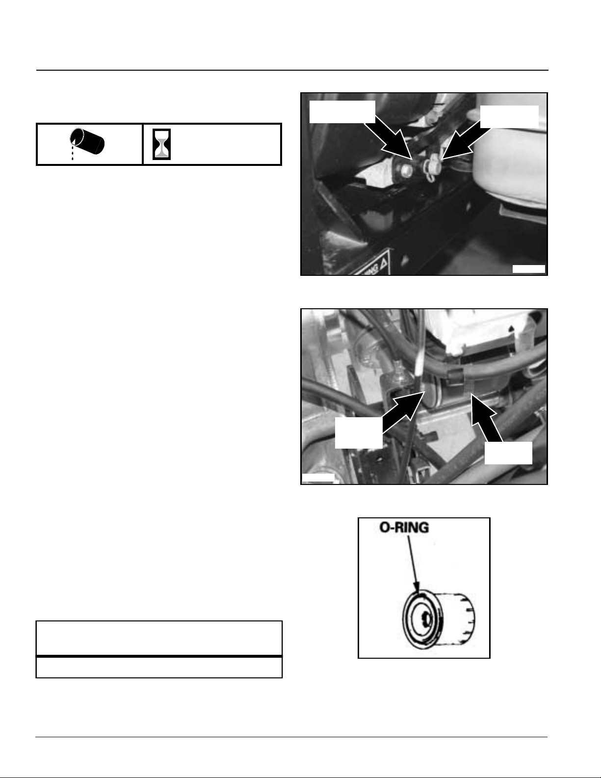
Table of Contents
Section 7 Lubrication and Fluids
Engine Oil and Filter Change
Refer to Figures 7-1, 7-2, 7-3, 7-4 & 7-5
100 hrs / 6 mos.
Drain used engine oil while the engine and oil are still
warm. The oil will drain more freely and carry away more
impurities. Change oil as follows:
1. Prepare vehicle for maintenance as outlined in steps
1-6 on page 24.
2. Clean the area around the oil filter to keep dirt and
debris out of the engine.
3. Place a suitable container below the engine to catch
used oil as it drains. Remove filler cap. Turn oil drain
valve 1/4 turn counterclockwiseand pull out to drain
oil.
4. Remove oil filter located on left side of engine with a
filter wrench. Let remaining oil drain out.
5. Push oil drain valve in and turn clockwise until hand
tight. Replace oil drain cap.
6. Clean oil filter base where the oil filter seats against it.
7. Place a new replacement filter in a shallow pan with
the open end up. Pour new engine oil in through the
threaded center hole until oil reaches the bottom of
the threads. Allow one or two minutes for the oil to be
absorbed by the filter material.
8. Coat new filter O-ring with clean engine oil and install
filter to engine filter base.
9. Hand tighten oil filter until O-ring seats.Finish
tightening by turning in the filter an additional 2/3 to 1
turn.
10. Dispose of used motor oil and filter in a manner that is
compatible with the environment. Do not throw used
oil in the trash, pour it on the ground, or down a drain.
11. Fill engine with recommended oil and quantity.Donot
overfill. See "Engine Oil Type and Capacity" and
"Engine Oil Level Check" on page 33.
12. Replace filler cap,start engine and check engine and
oil filter for leaks. Correct anyleaks before placing
engine into service.
13. Stop engine and check oil level. Add additional oil if
not to the full mark “F” on the dipstick.
Oil Drain Valve
Oil Filter
Base
22069
Oil Drain Cap
21363
figure 7-3
Oil Filter
Figure 7-4
Land Pride Oil Filter
Part No. Part Description
5205002 KOHLER ENGINE OIL FILTER
4400EX Heavy Duty Off Road Utility Vehicle 720-132M
34
21134
Oil Filter O-Ring
Figure 7-5
7/01/05
Page 37
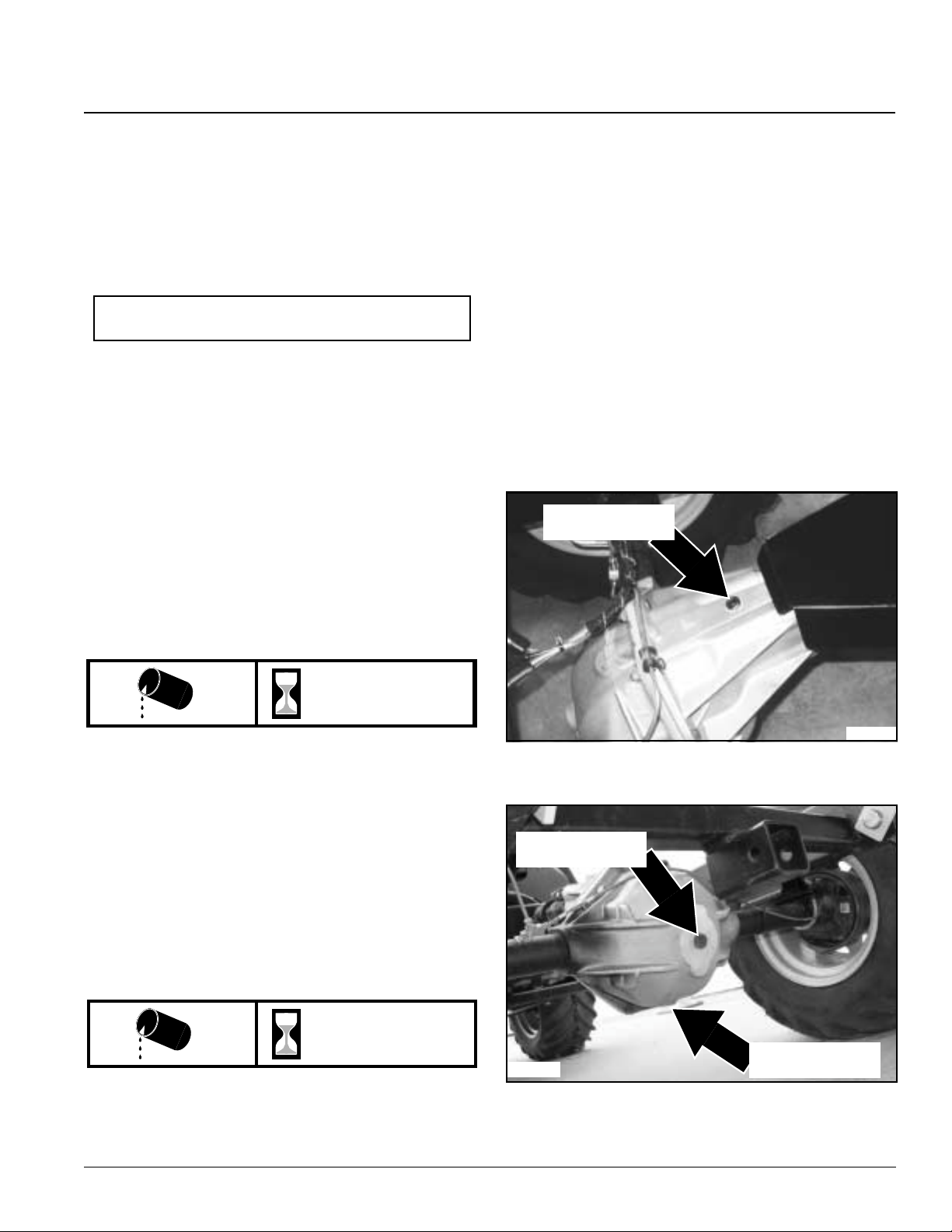
Section 7 Lubrication and Fluids
Table of Contents
Differential Oil
Refer to Figure 7-6 and Figure 7-7
Differential lubrication is essential and must be
maintained to ensure long life of the differentials. It is
extremely important to use proper type and weight of oil.
Also, it is important to check and change oil as outlined in
the maintenance schedule below.
NOTE: Running vehicle low on differential oil can
damage differential and void its warranty.
Differential Maintenance Schedule
• Check case housing for damage and possible oil
leakage after each use.
• Check gear lube level every 6 months or every 100
hours (whichever comes first).
• Change gear lube every 5 years or every 500 hours
(whichever comes first).
Differential Oil Type and Capacity
See also "Section 10 Specifications and Capacities" on
page 42.
• Type of lubrication: S.A.E 80-90 wt. GL-5 Gear Lube
• Lubrication capacity: 2 quarts or fill to bottom of check
plug opening.
Warm oil drainsquickly and completely. Drain used oil
while it is still warm as follows:
1. Parkvehicleonalevelsurface,set park brake,turnoff
ignition switch and remove switch key.
2. Place a suitable container below housing to catch
used oil. Remove fill plug, level plug and drainplug.
3. Allow used oil to drain completely and then reinstall
drain plug and tighten securely with 5 to 15 in. lbs. of
torque.
4. Disposeofusedoilinamannerthatis compatiblewith
the environment. Do not throw used oil in the trash,
pour it on the ground, or down a drain.
5. Fill front and rear differentialcases with 2 quarts or to
bottom of oil levelhole with recommended gear lube.
See "Section 10 Specifications and Capacities" on
page 42.
6. Replace fill plug and oil level plug. Tighten securely
with 5 to 15 in. lbs. of torque.
Oil Fill Plug
Differential Oil Level Check
100 hrs / 6 mos.
Check differential gear lube level at oil level check plugs
(SeeFigure7-6andFigure7-7).Gearlubelevelshouldbe
filled to edge of oil level check hole.
1. Prepare vehicle for maintenance as outlined in steps
1-6 on page 24.
2. Removeoillevelplug andverifyoil is levelwith bottom
of plug hole.
3. If low on oil, remove fill plug and add new differential
oil until oil is level with bottom of fill hole.
4. Replace both plugs and tighten securely with 5 to 15
in. lbs of torque.
Differential Oil Change
500 hrs / 5 yrs
Oil Level Plug
21365
21364
Figure 7-6
Oil Drain Plug
7/01/05
Figure 7-7
4400EX Heavy Duty Off Road Utility Vehicle 720-132M
35
Page 38
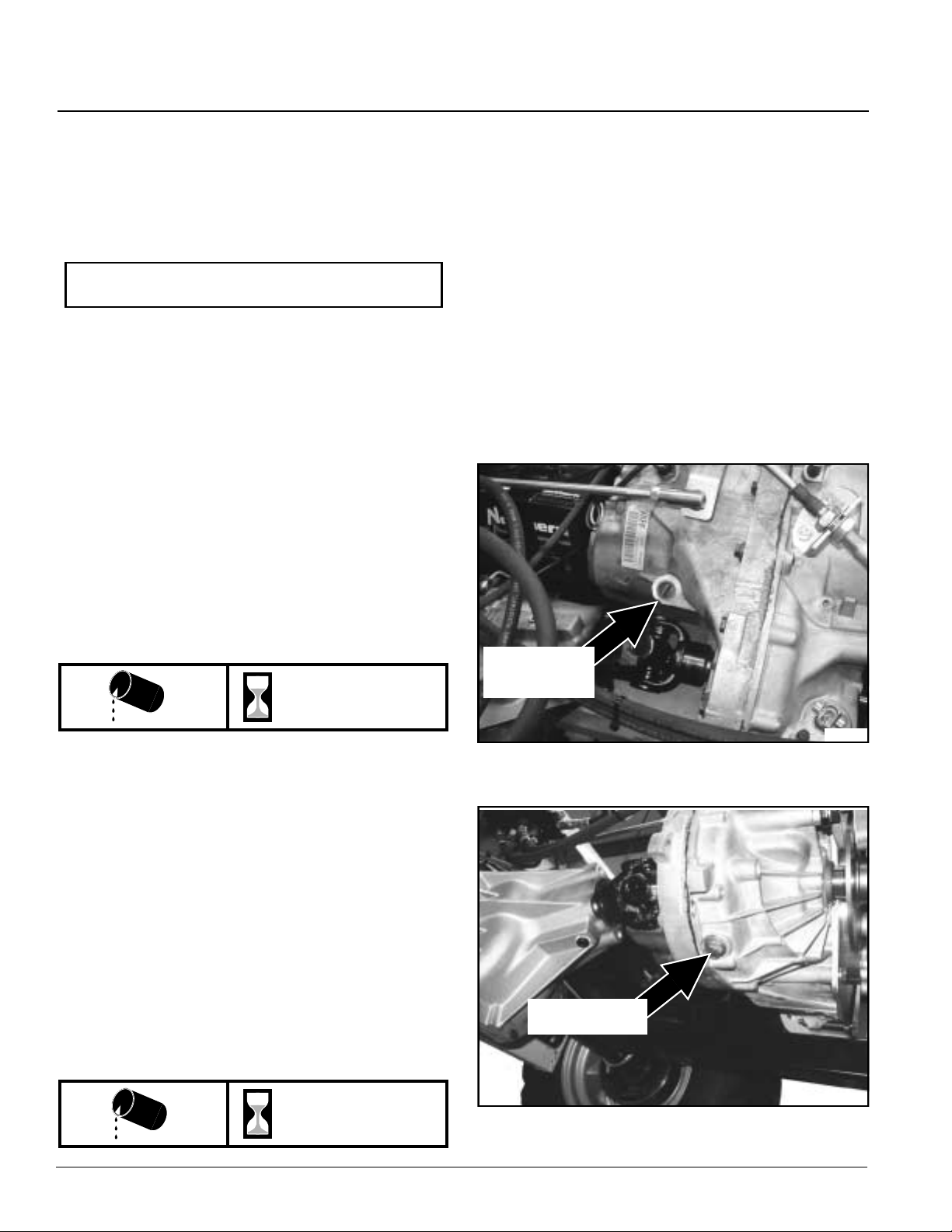
Section 7 Lubrication and Fluids
Table of Contents
Transmission Fluid
Transmission lubrication is essential and must be
maintained to ensure long life of the transmission. It is
extremely important to use proper fluid. Also, it is
important to check and change oil as outlined in the
maintenance schedule below.
NOTE: Running vehicle low on transmission oil can
damage transmission and void its warranty.
Transmission Maintenance Schedule
• Check case housing for damage and possible fluid
leakage after each use.
• Check transmission fluid level every100 hours or ever 6
months of operation, whichever comes first.
• Change transmission fluid every 1000 hrs or
immediately if water gets into it.
Transmission Fluid Type and Capacity
See also "Section 10 Specifications and Capacities" on
page 42.
• Type of Fluid: 5W30 Synthetic motor oil (S/N 460312+)
Dextron 3 automatic transmission fluid (S/N 460311-)
• Fluid capacity: 2 quarts or fill to the full mark, “H” mark
on the dipstick.
Warm oil drainsquickly and completely. Drain used oil
while it is still warm as follows:
1. Prepare vehicle for maintenance as outlined in steps
1-6 on page 24.
2. Place a suitable container below housing to catch
used oil. Remove dip stick and drain plug.
3. Allow used oil to drain completely and then reinstall
drain plug and tighten securely with 5 to 15 in. lbs. of
torque.
4. Disposeofusedoilinamannerthatis compatiblewith
the environment. Do not throw used oil in the trash,
pour it on the ground, or down a drain.
5. Fill transmission case with 2 quarts of Dextron 3
automatic transmission fluid at the dipstick port. Do
not overfill. See "Section 10 Specifications and
Capacities" on page 42.
6. Replace dipstick and check oil level.
Transmission Oil Level Check
Refer to Figure 7-8
100 hrs / 6 mos.
Check transmission oil level at the dip stick as follows:
1. Prepare vehicle for maintenance as outlined in steps
1-6 on page 24.
2. Allowenough time for transmission oil to settle before
checking oil level at the dipstick. Oil level may be
checked cold or after several hours of operation.
3. Clean around the dipstick before removing it to keep
dirt and debris out of the transmission.
4. Remove dipstick and wipe clean.
5. Fully insert dipstick and remove. Oil, hot or cold,
should be at the “H” mark on the dipstick but not over.
6. If oil level on dipstick is low,fill at the dipstick opening
withrecommendedoil.Repeatsteps3,4,5and6until
oil level on dipstick indicates full. Do not overfill.
Transmission Fluid Change
Refer to Figure 7-8 and Figure 7-9
Fill And
Oil Check
22083
Figure 7-8
Drain Plug
4400EX Heavy Duty Off Road Utility Vehicle 720-132M
36
1000 hrs
22082
Figure 7-9
7/01/05
Page 39
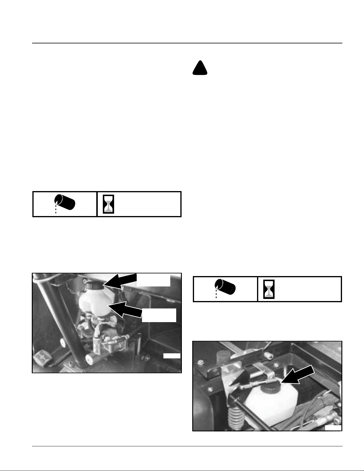
Section 7 Lubrication and Fluids
Table of Contents
Brake Fluid
Foryour safety and the safetyof others it is important that
themastercylinderfluidbe maintained. HaveaLandPride
Service Technician inspect the vehicle if the master
cylinder is loosing fluid frequently.
Brake Fluid Maintenance Schedule
• Check fluid reservoir monthly.
• Fill reservoir immediately if low or if braking capabilities
begin to fade.
Brake Fluid Type and Capacity
See also "Section 10 Specifications and Capacities" on
page 42
• Type of fluid: DOT 3
• Quantity: Fill to within 1/2” of reservoir opening.
Brake Fluid Level Check
Refer to Figure 7-10
Monthly
The master cylinder fluid reservoir is located behind the
steering column. Remove steering column shroud and
visually inspect fluid levelinthe reservoir.The fluid should
be within 1/2” of reservoir opening. Remove fill cap and
add DOT 3 fluid asneeded.
Steering & Cargo Lift Cylinder Fluid
!
WARNING
Hydraulic fluid under pressure can penetrate skin. Wear
protective gloves and safety glasses or goggles when working
withhydraulicsystems. use a piece of cardboardor wood rather
than hands when searching for hydraulic leaks. If hydraulic
fluid is injected into the skin, it must be surgically removed
within a few hours by a doctor or gangrene may result.
The hydraulic fluid operates the power steering, cargo lift
and hydraulic controlled accessory equipment. For your
safety and the safety of others it is important that the
hydraulic fluid be maintained. Ifthe reservoir is loosing
fluid frequently, have a Land Pride Dealer inspect the
vehicle.
Hydraulic Fluid Maintenance Schedule
• Check fluid reservoir monthly.
• Fill reservoir immediately if low or if hydraulics are
operating poorly.
Hydraulic Fluid Type and Capacity
See also "Section 10 Specifications and Capacities" on
page 42
• Type of fluid: Dextron 3 automatic transmission fluid
• Quantity: 2 quarts. Tank should be 3/4 full when all
accessories are in retracted position.
Hydraulic Fluid Level Check
Refer to Figure 7-11
Figure 7-10
Fill Cap
Reservoir
Monthly
The fluid reservoiris located on the driver’sside under the
seat. Visually inspect fluid level inside the reservoir.
Remove filler cap and addautomatic transmission fluid if
low.
22064
22070
Figure 7-11
7/01/05
4400EX Heavy Duty Off Road Utility Vehicle 720-132M
37
Page 40
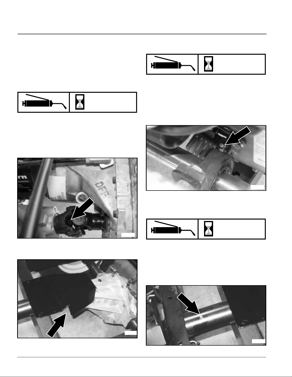
Section 7 Lubrication and Fluids
Table of Contents
Grease Type Lubrication
There are several points on the vehicle that require
lubrication. It is important that these points be lubricated
frequently to maintain ease of lever operation and to
ensure long bearing life.
Driveline U-Joints
Refer to Figure 7-12 and Figure7-13
100 hrs
Grease every 100 hours of operation
• Type of Grease: Multipurpose
• Quantity: 3 or 4 pumps of the grease gun. Stop adding
grease if lubricant is emerging through the seals.
Pillow Block Bearing
Refer to Figure 7-14
100 hrs
The Pillow block bearingis located along side the left side
of the engine below the fuel filter.
• Grease every 100 hours of operation
• Type of Grease: Multipurpose
• Quantity: 3 or 4 pumps of the grease gun.
Stop adding grease if lubricant emerges through the
seals.
Front Drive Line U-Joint
Figure 7-12
22067
Figure 7-14
Rotating Bearing Surfaces
Refer to Figure 7-15
Daily
22078
The swivel tube is located in the rear frame (See
Figure 7-15).
• Grease daily before putting into service
• Type of Grease: Multipurpose
• Quantity: Grease until lubricant emerges from one end
of the bushing.
Rear Drive Line U-Joint
Figure7-13
4400EX Heavy Duty Off Road Utility Vehicle 720-132M
38
21356
21356
Figure 7-15
7/01/05
Page 41
Table of Contents
Section 8 Seasonal Storage
Section 8 Seasonal Storage
!
CAUTION
Fuelvaporsareflammable and explosive.Donot store a vehicle
withfuelinthetankinabuilding where fumescanreacha spark
or an open flames (i.e. plug-in sockets, light switches, light
fixtures, power tools, welders, pilot lights and stoves).
Engine exhaust fumes contain carbon monoxide. Do not run a
vehicle inside a building any longer than what it takes to move
it. Serious illness or death may result from prolong exposure to
carbon monoxide.
Engine Preparation for Storage
1. Take vehicle out of gear, set park brake and run
engine outside for 15 minutes minimum. Then shut
vehicle off and remove ignition key.
2. Drain oil from crankcase while engine is still warm.
3. Change oil filter. Refer to page 34.
4. Refill with fresh oil of proper viscosity. Refer to
page 33.
5. Replace fuel filter if needed. Refer to page 28.
6. Prepare fuel system as follows:
Short term storage (90 days or less):
a. Siphon most of the fuel from the tank.
b. Add fuel stabilizer to the tank per manufacturers
recommendation.
IMPORTANT: Do not use fuel additives containing
methanol or ethanol.
8. Clean dirt and chaff from cylinders and fins, blower
housing and muffler.
9. Check oil fill cap and fuel tank cap to make certain
they are securely in place.
Vehicle Storage Preparation
1. Perform separate engine preparations listed
previously before storing the vehicle.
2. Store vehicle in a clean, dry place.
3. Always set park brake, leave vehicle in gear and
remove ignition key when parking the vehicle.
4. Before working around or on the vehicle, allow it to
cool.
5. Remove all dirt and trash.
6. Clean and touch up all scrapes per “Section 9 Body
Repair” on page 40.
7. Checkthoroughly for any worn or damaged parts that
need replacing including decals and order them from
your Land Pride Dealer.
8. Thoroughly lubricate the vehicle according to
lubrication instructions.
9. Block vehicle up to take weight off the tires.
NOTE: Do not deflate tires.
10. Clean battery and battery post. Check battery
electrolyte level. Protect battery from freezing
temperatures.Occasionallyrechargingbattery during
storage will extend battery life.
11. Secure a waterproof cover over the vehicle if stored
outside.
c. Fill fuel tank with fresh fuel to prevent water
condensation build-up.
d. Run engine to circulate fresh fuel throughout
engine components.
Long term storage (over 90 days):
a. Siphon most of the fuel from the tank.
b. Run engine until it stops from lack of fuel.
NOTE: Gasoline evaporates if left in carburetor for
longperiods, forming gum and varnish deposits in the
carburetor. These deposits will cause engine flooding
and loss of power.
c. Remove spark plugs and pour a tablespoon of
engine oil into each spark plug hole. Install plugs,
but do not reconnect plug leads.
d. Crank engine with starter at least a dozen
revolutionstodistributeoil over cylinder wallsand
valve mechanism.
7. Clean exterior surface of engine. Spread a light film of
oiloveranyexposedmetalsurfacesofenginethatare
subject to corrosion.
Vehicle Removal From Storage Preparation
1. Remove waterproof cover if used.
2. Clean vehicle, removing trash and dirt accumulation.
3. Install all safety shields and review safety precautions
listed in this manual.
4. Reconnect spark plug leads to spark plugs.
5. Check engine oil level.
6. Check transmission oil level.
7. Charge battery.
8. Fill fuel tank with fresh gasoline.
9. Run vehicle at half speed for 5 minutes, checking
operation of steering control levers.
10. Stop engine and check for oil leaks, loose fittings and
overall condition of the vehicle.
11. Tighten any bolts that may have loosened.
12. Check and inflate tires to correct air pressure.
7/01/05
4400EX Heavy Duty Off Road Utility Vehicle 720-132M
39
Page 42

Section 9 Body Repair
Section 9 Body Repair
Table of Contents
Introduction
Land Pride Gondo bodies are constructed of fiberglass.
Scuffs, light scratchesand deep gouges are in most
situations repairable. Land Pride recommends thatyou
use a professional body shop to restore your vehicle’s
body. For your consideration, we have provided below a
listof recommended tools, materialsandsteps suggested
for repairing the fiberglass body.
NOTE:LandPride does not supply the required tools,
paint and materialsneeded to repair the vehiclebody.
All tools, paint and materials should be purchased
locally.
Light Scuff
Required Tools and Materials
(See note above)
• 1,000 rpm buffing tool, DeWalt #849
• Meguiars buffing compound #8432
• Meguiars polish #8232 (optional)
• Meguiars maroon cutting pad #W-7006
• Meguiars tan polishing pad #W-9006 (optional)
• Meguiars backing plate #W-64
• Soft clean cotton cloths
Steps to Repair
1. Clean entire area of repair. Clean water is fine for this
purpose. Do not use solvent as this will damage the
body surface.
2. Install cutting pad #7006 on buffer (maroon pad).
3. Spread compound on area of repair, use about as
much as it takes to cover a half-dollar coin, this is a
good starting point.
4. Set buffing tool to lowest possible speed on dial, do
not buff at a high speed as this will heatand warp
material.
5. Buff damage area until surface scuff disappears. A
second and third application of compound may be
required. Keep buffer moving over surface, this will
help keep the surface cool. Clean compound residue
off surface after eachbuffing operation. Do not
continuetobuffcompounduntildry,orbuffthesurface
when dry. When all scuff marks have been buffed out
the surface may still appear a little dull, if so, proceed
to #6.
6. Install polish on surface as in step #3.
7. Spread #8232 polish on surface as in step #3.
8. Polish to a high luster oras required to match
surrounding material.
9. Wipe clean with soft clean cloth; any dirt on cloth will
mar surface.
Scratch
Required Tools and Materials
(See note to left)
• 1,000 rpm buffing tool, DeWalt #849
• Meguiars buffing compound #8432
• Meguiars polish #8232 (optional)
• Meguiars maroon cutting pad #W-7006
• Meguiars tan polishing pad #W-9006 (optional)
• Meguiars backing plate #W-64
• Soft clean cotton cloths
• 3M interface sanding pad #05774
• Air Vantage finishing sander with 6-inch hook and loop
pad
• 3M-P800 sanding film #00970
Steps to Repair
1. Clean entire area of repair. Clean water is fine for this
purpose. Do not use solvent as this will damage the
body surface.
2. Install interface-sanding pad ontofinishing sander.
Attach sanding film to Interface pad. (Take care in
centering sanding pad and film on sander.)
3. Sand surfaceusing about 45 P.S.I.air pressure at tool
inlet,donot sand at a high padspeed, because speed
causes the sanding film to load with dustand heats
the body surface. Proper sander pad speed is based
on cut and travel speed of pad, and downward
pressure applied by the operator. To clean sanding
pad surface, run sanderface at 90 degrees on the
edge of a piece of cardboard. This cleaning operation
will help keep the sanding film clean and run cooler.
Continue to sand surface until original scratch
damage is no longer visible. Wipe the surface with a
cloththeninspectto be sure the entire originalscratch
has been fully sanded away (very important).
4. Install cutting pad #7006 on buffer (maroon pad).
5. Spreadcompound #8432 onarea of repair,useabout
as much as it takes to cover a half-dollar coin, this is a
good starting point.
6. Set buffing tool to lowest possible speed on dial, do
not buff at a high speed as this will heatand warp
material.
7. Buff sanded area until surface scuff disappears.
4400EX Heavy Duty Off Road Utility Vehicle 720-132M
40
7/01/05
Page 43

Table of Contents
Section 9 Body Repair
8. A second and third application of compound may be
required. Keep buffer moving over surface, this will
help keep the surface cool. Clean compound residue
off surface after each buffing operation. Do not
continue to buff compound until dry.
9. Buff the surface of thebody when dry. When all scuff
marks have been buffed out the surface may still
appear a little dull, if so, proceed to #10.
10. Install polishing pad #W-9006 on buffer (tan pad).
11. Spread #8232 polish on surface as in step #3.
12. Polish to a high luster or as required to match
surrounding material.
13. Wipe clean with
mar surface.
soft clean cloth; any dirt on cloth will
Deep Gouge
Required Tools and Materials
(See note on page 39)
• 1,000 rpm buffing tool, DeWalt #849
• Evercoat Body Filler Easy Sand
• Sanding Pad
• DuPont Full-Thane Primer 421-15
• DuPont 3939 Cleaner
• DuPont Sealer 42470
• DuPont Chroma Base/ Clear Coat Paint System
• HVLP Paint Sprayer
Steps to Repair
1. Sand damaged area with 500-grit paper to remove
raisededgesandtocreate abraded surfaceforproper
adhesion.
2. Fill damaged area with Evercoat body filler (2-part
system) and allow to completely dry.
3. Sanddown high spots with 500-grit paper.Ifrecesses
are still visible due to filler shrinkage, apply second
skimcoatandagain allow todry completely,thensand
surface flush with surrounding area.
4. Apply DuPont Full-Thane Primer 421-15 over body
filler.
5. Once primer is completely dry, clean surface with
DuPont 3939 Cleaner and again allow surface to dry
completely.
6. Apply 42470 Sealer over body filler.
7. Apply color-matched paint system with HVLP paint
sprayeraccording to supplier’s recommendations.
7/01/05
4400EX Heavy Duty Off Road Utility Vehicle 720-132M
41
Page 44
Table of Contents
Section 10 Specifications and Capacities
Section 10 Specifications and Capacities
4400EX Series Gondo
Engine Kohler Command Pro Series Body Cowling Fiberglass
Engine Type 4 stroke - air cooled V-Twin Floorboards Fiberglass
Horse Power 20 Frame Construction Tube & channel
Displacement 624 cc Frame. Suspension Pivoting interactive
Cylinders 2 Fenders Front: Integral
Rear: Bed mounted
Valving OHV Front Bumper Standard
Lubrication Pressurized Front Brush Guard Optional
Engine Oil Type SAE 10W30 Seating Buckets - 2
Engine Oil Capacity 2 US quarts
1.9 Liters
Engine Idle rpm 1100 r pm +/- 100 rpm Rear Hitch 2” receiver
Maximum Engine Static rpm 3800 rpm Approximate Curb Weight 1400 lbs.
Max. Torque 32.5 lb@2600 Total Payload of Base Unit 2200 lbs.
Cooling Air Total Gross Vehicle Weight 3600 lbs.
ACG Output 12V/20A Rear Cargo Box Capacity 1800 lbs.
Ignition Keyed Maximum Tongue Weight 250 lbs.
Battery 300 cca Maximum Towing Capacity
Spark Arrestor Standard Wheel Base 68”
Headlights Standard Tread Center Front 43"
Tail Lights Standard Tread Center Rear 43"
Fuel Capacity 8 gallons Width at front tires 56"
Fuel Type Unleaded fuel with 87 min
octane (Methanol fuel not
allowed)
Front & Rear Differential
Oil Capacity and Type
Transmission Case
Fluid Capacity and Type
Transmission 5 - speed
Gear Selection 5 - forward and 1- reverse Length 117” without cargo box
Max. Speed up to 17 mph Floorboard Height With bar tires: 14"
Brakes Front: Hydraulic drum
Brake oil DOT 3 Tire Size (Bar & Turf) 4-ply 26x12-12
Steering & Cargo Lift Type Hydrostatic steering
Steering & Cargo Reservoir
Fluid Capacity & Type
Steering Wheel Dia. 14"
2 US qts. S.A.E 80-90wt.
GL-5 Gear Lube
2 US qts. Mobil 5w30
synthetic oil (S/N 460312+)
manual transmission
Rear: Hydraulic drum
Hydraulic lift
2 US qts. Dextron 3
automatic transmission fluid
Tire Pressure (Rear) 20 psi**
Width at rear tires 56”
Inside Turning Radius
Inside Turning Circle
Outside Turning Circle
Angle of Oscillation
Inches of Rise
Min. Ground Clearance 7 1/2”
Tire Pressure (Front) 15 psi
ROPS Standard
2500 lbs.
8’-4”
16’-8”
25’-0”
16
14”
Height 54.5” top of steering
wheel
76.5” top of ROPS
135” with cargo box
With turf tires: 13.5”
o
**
Tire pressure may be increased to accommodate additional cargo load. Max.tire pressure is noted on tire side wall.
4400EX Heavy Duty Off Road Utility Vehicle 720-132M
42
7/01/05
Page 45
Table of Contents
Section 11 Features And Benefits
Section 11 Features And Benefits
4400EX Series
Features Benefits
20hp OHV V-Twin Kohler
Command Pro Series Engine
Fully Articulating
and Oscillating Interactive Frame
Fully Certified
(Roll Over Protection System)
Five-speed Automotive Transmission For excellent power, pulling performance and speed range selection.
Full-time Four Wheel Drive For maximum traction.
Dana Differentials Front and Rear For maximum traction and durability.
4-Wheeled Automotive Style Braking For Maximum Stopping Power & Control
Hydrostatic Power Steering. For easy handling and higher productivity.
Hydraulic Dumping Cargo Bed For Maximum Productivity
Lever Activated Hydraulic Outlets For powered cargo dump and front blade lift.
2200lb Total Payload Capacity For high productive cargo, gear hauling, & passenger transport capabilities.
Eight-gallon Fuel Tank For extended operating range in off-road conditions.
56" Wheel Stance For Excellent Stability
High Ground Clearance
13.5" Under Floorboard
Large Open Operator’s Station For passenger and operator comfort.
High Back Type Bucket Seats For passenger and operator comfort.
Cab-over Suspension System
on Front Cowling
Forward Tilting Cab Console For maximum ease of service.
Standard Two Inch Receiver Hitch For pulling power and added versatility.
Choice of Bumper or Brush Guard To meet specific performance needs.
Choice of Three Cargo Boxes For maximum versatility.
Wide Range of Accessories For added versatility and operator convenience.
Warranty One year against manufacturing defects.
Proven power, dependability, and fuel efficiency.
For excellent stability and ground hugging traction on extreme terrain.
For increased protection when needed.
Enables extreme trail capability.
For operator comfort.
Two years manufacture’s engine warranty.
7/01/05
4400EX Heavy Duty Off Road Utility Vehicle 720-132M
43
Page 46
Table of Contents
Section 12 Troubleshooting
Section 12 Troubleshooting
Symptoms Probable Causes Suggested Remedies
Battery is dead
Battery will not charge up
Brakes are sticking (won’t release)
Brakes don’t function
Electrical system does not work
Key switch is not in the off position. Switch key to off position.
Battery is worn out or defective. Replace battery.
Starter solenoid is shorted. Replace starter solenoid.
Battery connections are loose or
corroded.
Battery fluid level is low. Add distilled water to battery cell.
Battery cell is dead. Replace battery.
Battery is worn out or defective.
Master cylinder linkage is out of
adjustment.
Master cylinder return spring is broken. Replace master cylinder return spring.
Ground debris in brake linkage. Clean debris from brake linkage.
Master cylinder oil level is low. Add brake fluid to the master cylinder.
Brake line is broken. Replace brake line.
Brake line has air in it. Bleed brake line and add brake fluid.
Master cylinder is defective. Replace master cylinder.
Electrical fuse is blown or missing. Replace electrical fuse.
Battery connections are loose or
corroded.
Disconnect and recharge battery.
Clean and tighten battery connections.
Adjust master cylinder linkage.
Clean and tighten battery connections.
Clutch is malfunctioning
Engine backfires
Engine knocks
Battery is worn out or defective. Replace battery.
Ignition switch is defective. Replace ignition switch.
Clutch does not engage. Readjust clutch linkage and/or replace
Clutch does not disengage. Readjust clutch linkage and/or replace
Clutch worn out. Replace clutch.
Spark plug is fouled. Replace or clean spark plug.
Air intake restrictor upstream of air
cleaner is missing or incorrectly
installed.
Throttle cable is defective or out of
adjustment.
Engine speed is set too low. Adjust engine idle screw.
Engine is overloaded. Avoid overloading the engine.
Fuel is stale or dirty. Replace fuel with new fuel.
throw-out bearing.
throw-out bearing.
Replace or correctly install air intake
restrictor.
Clean and oil throttle cable. Replace
worn or damaged cable.
4400EX Heavy Duty Off Road Utility Vehicle 720-132M
44
7/01/05
Page 47
Table of Contents
Section 12 Troubleshooting
Symptoms Probable Causes Suggested Remedies
Engine loses power
Engine overheats
Throttle cable is sticking. Clean and oil throttle cable. Replace
Choke cable is sticking. Clean and oil choke cable. Replace
Spark plugs are defective. Replace spark plugs.
Spark plugs are fouled. Clean spark plugs or replace.
Fuel supply is restricted. Check for dirt in fuel tank.
Fuel line is plugged, pinched, or kinked. Clean or replace fuel line.
Fuel leaks into the crankcase. Clean or replace fouled spark plugs.
Engine oil level is high. Drain excess oil, check for gas in the
Fuel octane is incorrect. Use unleaded 87 minimum octane.
Throttle cable is faulty or out of
adjustment.
Air cleaning element is plugged. Replace or clean air cleaner with air.
Engine is overheating. See Symptoms for engine
Engine cooling fins are plugged. Allow engine to cool. Clean cooling
worn or damaged cable.
worn or damaged cable.
Verify choke position is not stuck on.
oil.
Adjust or replace throttle cable.
overheating.
fins with high pressure air.
Engine runs unevenly
Engine oil level is low. Add specified engine oil.
Carburetor air intake tube is plugged. Clean air intake tube.
Air cleaning element is plugged or
missing.
Electrical connections are loose. Reattach electrical connections.
Engine cooling fins are plugged. Allow engine to cool. Clean cooling
Throttle cable is sticking. Clean and oil throttle cable. Replace
Choke cable is sticking. Clean and oil choke cable. Replace
Fuel is stale or dirty. Replace fuel with new fuel.
Fuel line is plugged. Clean fuel line.
Fuel type is incorrect. Use unleaded 87 minimum octane.
Fuel leaks into the crankcase. Clean or replace fouled spark plugs.
Spark Plug wiring is defective. Replace spark plug wiring.
Spark plug is defective. Replace spark plugs.
Spark plug is fouled. Clean spark plugs or replace.
Replace or clean air cleaner with air.
fins with high pressure air.
worn or damaged cable.
worn or damaged cable.
(Methanol not allowed).
Verify choke position is not stuck on.
7/01/05
Carburetor is not adjusted correctly. Adjust carburetor.
Air cleaner is plugged. Replace or clean air cleaner with air.
4400EX Heavy Duty Off Road Utility Vehicle 720-132M
45
Page 48
Table of Contents
Section 12 Troubleshooting
Symptoms Probable Causes Suggested Remedies
Engine starts in gear
Engine stops running
Gear Shift is malfunctioning
Park brake doesn’t work
Clutch switch is improperly adjusted. Adjust clutch switch to be engaged
with clutch fully down.
Gas tank is empty. Refill gas tank.
Spark Plug wiring is defective. Replace spark plug wiring.
Ignition switch is defective. Replace ignition switch.
Battery is worn out or defective. Replace battery
Crankshaft is broke. Replace broken crankshaft.
Clutch is not fully depressed. Fully depress clutch.
Clutch plate does not release. Adjust clutch linkage
Shift linkage is out of adjustment. Adjust shift linkage.
Synchronizer is defective. Replace synchronizer.
Transmission jumps out of gear. Withgear shift in neutral, adjust shifter
link at transmission to be in neutral
position.
Park brake cable is broken. Replace park brake cable.
Park brake cable is jammed with debris. Clean debris from park brake cable.
Park brake is out of adjustment. Adjustknobon end of park brake lever
clockwise to tighten brake tension and
counterclockwise to loosen brake
tension.
Starter cranks slowly
Battery power is low. Recharge battery.
Battery connections are loose or
corroded.
Battery is worn out or defective. Replace battery.
Harness connections are loose. Reconnect harness connections.
Harness pin connections are bent. Straighten harness pins.
Harness is defective. Replace harness.
Ignition switch is defective. Replace ignition switch.
Starter is defective. Replace starter.
Engine oil is too heavy. Replace with SAE 10W30 oil.
Clean and tighten battery connections.
4400EX Heavy Duty Off Road Utility Vehicle 720-132M
46
7/01/05
Page 49
Table of Contents
Section 12 Troubleshooting
Symptoms Probable Causes Suggested Remedies
Starter does not work
Steering does not track correctly
Steering play is excessive
Vehic le speed does not reach 17 MPH
Neutral switch is not engaged. Adjust neutral switch to be engaged
Neutral switch is defective. Replace neutral switch.
Battery power is low. Recharge battery.
Battery connections are loose or
corroded.
Battery is worn out or defective. Replace battery.
Harness connections are loose. Reconnect harness connections.
Harness pin connections are bent. Straighten harness pins.
Harness is defective. Replace harness.
Ignition switch is defective. Replace ignition switch.
Starter is defective. Replace starter switch.
Improper tire inflation. Inflate all tires to correct tire pressure.
Hydraulic steering cylinder is not
operating properly.
Worn mounting bushings at hydraulic
cylinder connecting pins.
Malfunctioning steering sector. Inspect and repair worn parts.
Throttle cable housing is set too close to
engine preventing proper cable
movement.
with gear shift in neutral.
Clean and tighten battery connections.
Inspect thoroughly and replace or
tighten malfunctioning components.
Inspect and replace all worn bushing
and connecting pins.
Repositioncablehousingtowardseats
until all cable slack is removed
between cable housing and engine.
Vehic le looses ground speed without
loosing engine speed
Carburetor is icing up. Install Cold Weather Kit.
Clutch out of adjustment. Adjust clutch linkage.
Clutch worn out. Replace clutch.
7/01/05
4400EX Heavy Duty Off Road Utility Vehicle 720-132M
47
Page 50
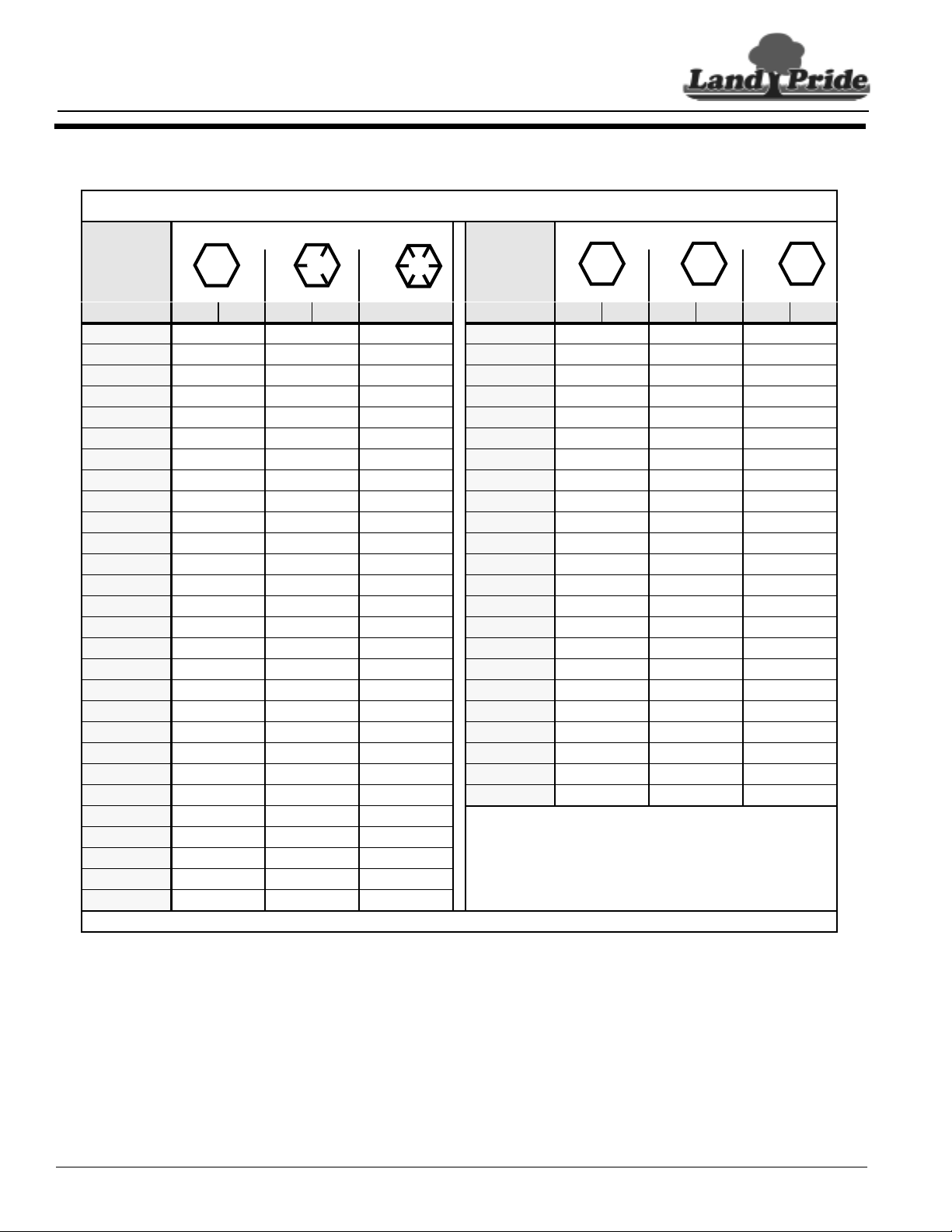
Section 13 Appendix
Section 13 Appendix
Torque Values Chart
Bolt Head Identification
Table of Contents
Bolt Head Identification
Bolt Size
(Inches)
in-tpi
1/4" - 20 7.4 5.6 11 8 16 12 M 5 X 0.8 4 3 6 5 9 7
1/4" - 28 8.5 6 13 10 18 14 M 6 X 1 7 5 11 8 15 11
5/16” - 18 15 11 24 17 33 25 M 8 X 1.25 17 12 26 19 36 27
5/16" - 24 17 13 26 19 37 27 M 8 X 1 18 13 28 21 39 29
3/8" - 16 27 20 42 31 59 44 M10 X 1.5 33 24 52 39 72 53
3/8" - 24 31 22 47 35 67 49 M10 X 0.75 39 29 61 45 85 62
7/16" - 14 43 32 67 49 95 70 M12 X 1.75 58 42 91 67 125 93
7/16" - 20 49 36 75 55 105 78 M12 X 1.5 60 44 95 70 130 97
1/2" - 13 66 49 105 76 145 105 M12 X 1 90 66 105 77 145 105
1/2" - 20 75 55 115 85 165 120 M14 X 2 92 68 145 105 200 150
9/16" - 12 95 70 150 110 210 155 M14 X 1.5 99 73 155 115 l215 160
9/16" - 18 105 79 165 120 235 170 M16 X 2 145 105 225 165 315 230
5/8" - 11 130 97 205 150 285 210 M16 X 1.5 155 115 240 180 335 245
5/8" - 18 150 110 230 170 325 240 M18 X 2.5 195 145 310 230 405 300
3/4" - 10 235 170 360 265 510 375 M18 X 1.5 220 165 350 260 485 355
3/4" - 16 260 190 405 295 570 420 M20 X 2.5 280 205 440 325 610 450
7/8" - 9 225 165 585 430 820 605 M20 X 1.5 310 230 650 480 900 665
7/8" - 14 250 185 640 475 905 670 M24 X 3 480 355 760 560 1050 780
1" - 8 340 250 875 645 1230 910 M24 X 2 525 390 830 610 1150 845
1" - 12 370 275 955 705 1350 995 M30 X 3.5 960 705 1510 1120 2100 1550
1-1/8" - 7 480 355 1080 795 1750 1290 M30 X 2 1060 785 1680 1240 2320 1710
1 1/8" - 12 540 395 1210 890 1960 1440 M36 X 3.5 1730 1270 2650 1950 3660 2700
1 1/4" - 7 680 500 1520 1120 2460 1820 M36 X 2 1880 1380 2960 2190 4100 3220
1 1/4" - 12 750 555 1680 1240 2730 2010
1 3/8" - 6 890 655 1990 1470 3230 2380
1 3/8" - 12 1010 745 2270 1670 3680 2710
1 1/2" - 6 1180 870 2640 1950 4290 3160
1 1/2" - 12 1330 980 2970 2190 4820 3560
Torque tolerance + 0%, -15% of torquing values. Unless otherwise specified use torque values listed above.
1
Grade 2 Grade 5
Grade 8
N · ft-lb N · ft-lb N · ft-lb mm x N · ft-lb N · ft-lb N · ft-lb
Bolt Size
(Metric)
1
in-tpi = nominal thread diameter in inches-threads per
2
N· m = newton-meters
3
ft-lb= foot pounds
4
mm x pitch = nominal thread diameter in millimeters x
5.8 8.8 10.9
Class 5.8 Class 8.8 Class 10.9
4400EX Heavy Duty Off Road Utility Vehicle 720-132M
48
7/01/05
Page 51

Section 13 Appendix
Land Pride, A Division of Great Plains Manufacturing, Inc., 1525 East North Street, Salina, Kansas, USA
(hereinafter“Land Pride”) warrantsfor aperiod oftwelve (12) monthsfrom thedate ofinitial retailpurchase
from anauthorized Land Pride UtilityVehicle dealer that each newLand Pride Utility Vehicleshall be free,
under normaluse and maintenance, fromany defect in material andworkmanship subject to thefollowing
conditions, exclusions, obligations and limitations.
1. Coverage Any material or workmanship found and determined to be defective by Land Pride within the
(12) twelve month warranty period shall be remedied without charge for parts or labor at any authorized
Land Pride Utility Vehicle dealership.
2. Owner’s Obligations The following obligations must be fulfilled by the owner to maintain the validity of
Land Pride warranty:
a. The original owner must service the vehicle according tothe periodic maintenance charts contained in
the Operator’s Manual as neglecting to do so can impede the warranty process. These inspections,
maintenance services and adjustments are to be performed at the owner’s expense.
b. The owner must present a copy of the warranty registration card or other positive proof of initial retail
purchase date issued at the time of purchase, to an authorized Land Pride Utility Vehicle dealer at the
time the warranty repairs are to be performed on the vehicle.
3. Exclusions The following are specifically excluded from this warranty:
a. Any Land Pride Utility Vehicle used for rental purposes.
b. Any Land Pride Utility Vehicle used to tow loads in excess of the maximum trailer weight specified in
the Operator’s Manual.
c. Any Land Pride Utility Vehicle used to carry loads in excess of the maximum vehicle load rating
including occupants and cargo as stated in the Operator’s Manual.
d. Any Land Pride Utility Vehicle that has been altered or modified without Land Pride’s specific
recommendation, approval and authorization in writing.
e. Any Land Prideaccessories that arecovered by theLand Pride Parts and AccessoriesWarranty Policy.
f. Any Land Pride UtilityVehicle that has not beencompletely and properly assembled and pre-delivered
by an authorized Land Pride Utility Vehicle dealer.
4. Limitations This warranty shall not apply to or include any of the following:
a. Repair or replacement required as result of (I) accident, (II) misuse or neglect, (III) lack of reasonable
and proper maintenance, (IV) repairs improperly performed or replacements improperly installed, (V)
use of replacement parts or accessories not conforming to Land Pride specifications which adversely
affect performance and/ordurability, (VI) alterations or modifications notrecommended or approved in
writing by Land Pride and/or (VII) wear and deterioration occasioned by the use of this vehicle.
b. Pre-delivery, routine maintenance, service and adjustments.
c. Engine (Warranty is covered by the original engine manufacturer).
d. Tires, belts, shocks, brakes and body (Considered wear items).
5. Limited Liability The liability of Land Pride under the twelve (12) month warranty is limited solely to the
remedying ofdefects in materials or workmanship byan authorized Land Pride Utility Vehicledealer at its
place of business during customary business hours. This warranty does not cover inconvenience, loss of
use of the vehicle, or transportation of thevehicle to or from the Land Pride dealer. Land Pride shall not
be liable for any other expense, loss, or damage, whether direct, incidental, consequential, or
exemplary arising in connection with the sale or use of or the inability to use the LandPride Utility
Vehicle for any purpose. Some states, provinces or countries do not allow the exclusion or limitation of
any incidental or consequential damages, so the above limitation or exclusion may not apply to you.
a. No express warranty is given by Land Pride with respect to the Land PrideUtility Vehicle except as set
forth herein. Any warranty implied by law, including any warranty of merchantability or fitness for a
particular purpose, is expressly limited to the twelve (12) month warranty terms set forth herein. The
foregoingstatements of warrantyare exclusiveand inlieu ofall other remedies.Some states,provinces
or countries donot allow limitations on how long an implied warrantylasts, so the above limitation may
not apply to you.
b. No dealer is authorized to modify this Land Pride Utility Vehicle Warranty.
c. Any breach of warranty claim must be brought forth within 15 months of original sale.
6. Legal Rights This warranty givesyou specific legal rights and you may also have other rights whichvary
from state, province or country.
Effective January 2, 2003
Table of Contents
Land Pride Limited Warranty
Utility Vehicle
7/01/05
4400EX Heavy Duty Off Road Utility Vehicle 720-132M
49
Page 52

Corporate Office: P.O. Box 5060
Salina, Kansas 67402-5060 USA
www.landpride.com
 Loading...