

Landi Renzo V05 Instruction Manual
PROGRAMMER TESTER
Mod. V05
190164440
INSTRUCTIONS MANU AL

LANDI RENZO S.P.A. reserves the right to make improvements or modifications to its products at any time, at its own judgement and without notice thereof.
CONTENENTS
TESTER PARAMETERS AND VALUES THAT CAN BE SELECTED.............................pag 3
ARRANGEMENT OF PAGES OF PROGRAMMER TESTER mod. V05 ........................pag 5
DATA DISPLAY PAGE .....................................................................................................pag 6
EXAMPLE OF PROGRAMMING ....................................................................................pag 7
NUMBER OF CYLINDERS (IGNITION) .........................................................................pag 8
RPM SIGNAL TYPE........................................................................................................pag 8
TYPE OF CHANGE PETROL-GAS ................................................................................pag 8
RPM SELECTION FOR CHANGE OVER ......................................................................pag 8
OVERLAP TIME..............................................................................................................pag 8
TYPE OF TPS.................................................................................................................pag 8
INDICATOR SENSOR TYPE ..........................................................................................pag 9
LAMBDA SENSOR TYPE...............................................................................................pag 9
LAMBDA SENSOR READING DELAY ...........................................................................pag 9
SIMULA TION TYPE ........................................................................................................pag 10
SQUARE W A VE SIMULATION .......................................................................................pag 10
MAXIMUM OPEN TRHOTTLE OPTION.........................................................................pag 11
OPEN THROTTLE POSITION ........................................................................................pag 11
TPS FOR MAXIMUM OPEN THROTTLE .......................................................................pag 11
MAXIMUM ACTUATOR POSITION ................................................................................pag 12
TPS TO RELEASE LIMITATION .....................................................................................pag 12
MINIMUM ACTUATOR POSITION..................................................................................pag 12
CUTOFF OPTION...........................................................................................................pag 12
MINIMUM RPM FOR CUTOFF.......................................................................................pag 13
POSITION ON CUTOFF................................................................................................. pag 13
FIXED DEFAULT OPTION ..............................................................................................pag 13
FIXED DEFAULT POSITION VALUE ..............................................................................pag 13
MEMORY DELETION.....................................................................................................p ag 13
DIAGNOSIS MODE ........................................................................................................pag 14
CARBURATION LEARNING PROCEDURE ...................................................................pag 15
Programmer tester Mod. V05
3
FEATURES
The Programmer Tester Mod. V05 is used to program and diagnose the LCS-A/1 V05 system.
It display parameters that characterize the operation of the entire system such as the lambda value (whether on
gas or petrol), the position of the linear actuator with the stepper motor and its default, the engine speed, and TPS
signal.
The Programmer Tester Mod. V05 is supplied directly by the cable linking it with the LCS-A/1 V05 central unit.
OFFERS
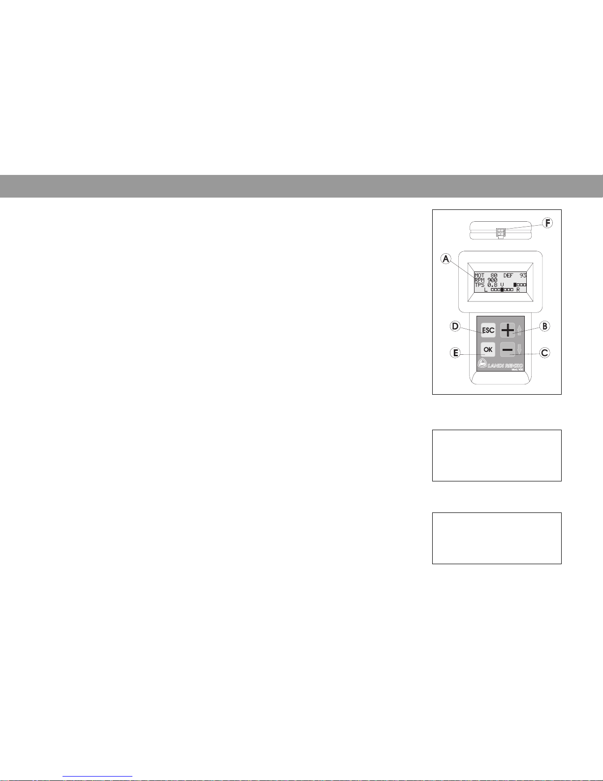
(fig.1)
The keypad offers different controls depending on the “page” the tester is on.
A) Alphanumerical display.
B) Button that shifts the cursor upwards, increases the value and passes on to the previous “page”.
C) Button that shifts the cursor downwards, decreases the value and passes on to the next “page”.
D) Button to quit the “page”.
E) Button that confirms the figure and goes into value modify mode.
F) Connector for connection with the interface cable.
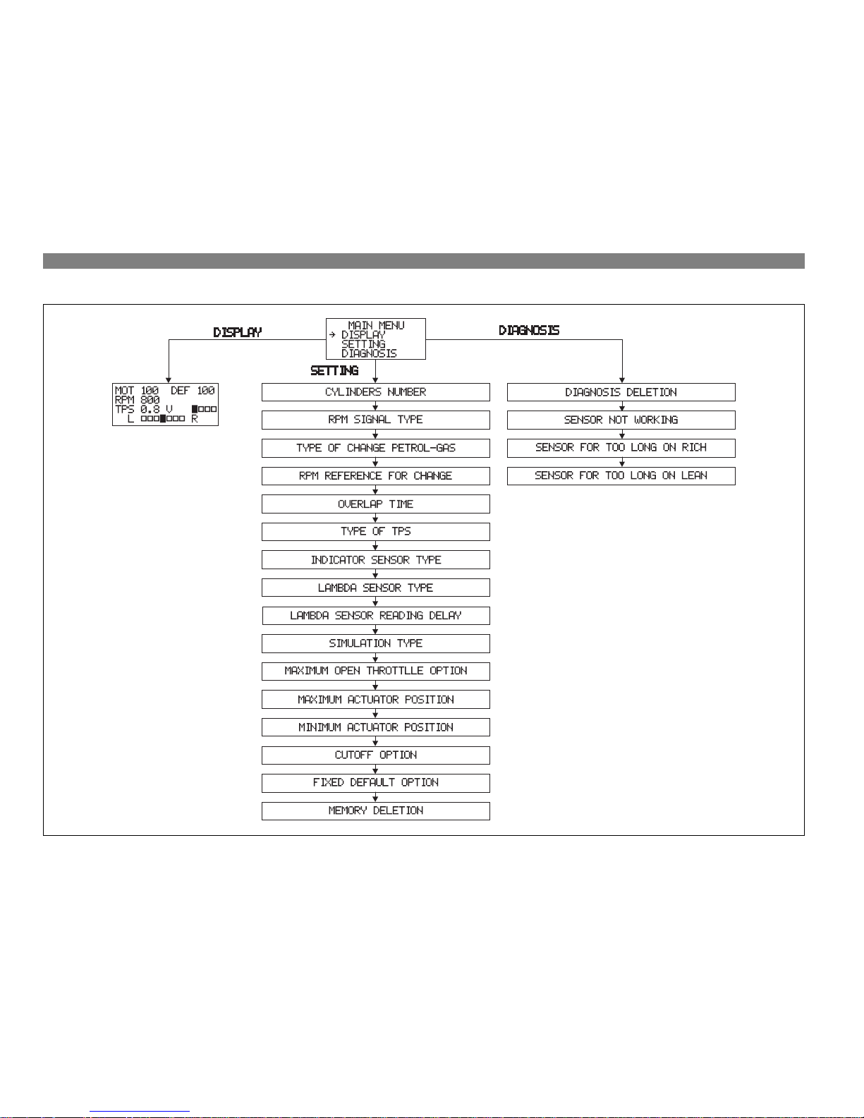
The first page displayed on activating the tester is the MAIN MENU, (fig. 2).
Description of main elements, fig. 1
TESTER PARAMETERS AND VALUES THAT CAN BE SELECTED
Display menu (fig. 3)
Makes it possible to know the following values in real time:
• Value of default position of linear actuator with stepper motor.
• Engine speed.
• TPS value.
• Lambda sensor signal indicator.
MAIN MENU
^ DISPLAY
SETTING
DIAGNOSIS
Main menu, fig. 2
MOT 80 DEF 80
RPM 800
TPS 1.8 V ][]]
L ]]][]]] R
Display menu, fig. 3
PROGRAMMER - TESTER Mod. V05

4
Landi Renzo S.p.A.
TECHNICAL DA T A
Setting menu options
Number of cylinder (ignition) ............................................................................................ 4,5,6,8 cylinders, coilpack, single-coil
RPM signal type................................................................................................................ ........................ weak signal, standard
Type of change petrol-gas.................................................................................................... deceleration, acceleration, option2
RPM reference for change ....................................................................................................................................400-9000 rpm
Overlap time.....................................................................................................................................................................0-1 sec.
Type of TPS (throttle position sensor).................... 5-0V, 0-5V linear, 0-12V switch,12-0V switch, Mono Bosch, TPS adapter
Indicator sensor type ........................................................................................................................ Landi Renzo, AEB, 0-90 Ω
Lambda sensor type ..........................................................................................................................0-1V, 0-5V, 5-0V, 0.8-1.6V
Lambda sensor reading delay .................................................................................................................................. 0-1250 sec.
Simulation type ................................................................................................................ .. Square wave, disconnected, ground
- High time
1
............................................................................................................................................................................................................................................................................................
0-5 sec.
- Low time
1
.............................................................................................................................................................................................................................................................................................
0-5 sec.
- Disconnected sensor time
1
.......................................................................................................................................................................................................................................
0-654 sec.
- N waves after disconnection
2
.................................................................................................................................................................................................................................
0-255 sec.
Maximum open throttle option ................................................................................................... ................ enabled, not enabled
- Open throttle position
3
.............................................................................................................................................................................................................................................
40-240 steps
- TPS for maximum open throttle
3
....................................................................................................................................................................................................................................
1.5-5V
Maximum actuator position..................................................................................................................................... 20-240 steps
- TPS to release limitation
4
............................................................................................................................................................................................................................................................
0-5V
Minimum actuator position...................................................................................................................................... 20-240 steps
Cutoff option .................................................................................................................. ............................. enabled, not enabled
- Minimum rpm for cutoff
5
.................................................................................................................................................................................................................................
1000-4000 rpm
- Position on cutoff
5
........................................................................................................................................................................................................................................................
20-240 steps
Fixed default option ................................................................................................................................... enabled, not enabled
- Fixed default position value
6
.............................................................................................................................................................................................................................
20-240 steps
Diagnosis menu
Diagnosis deletion
Lambda sensor not working
Lambda sensor too long on rich
Lambda sensor too long on lean
1
The parameter is displayed if the type of emulation is set on SQUARE WAVE.
2
The parameter is displayed if the disconnected sensor time is greater than 0.
3
The parameter is displayed if the open throttle option is ENABLED.
4
The parameter is displayed if the maximum actuator opening option is less than 240.
5
The parameter is displayed if the cut-off option is ENABLED.
6
The parameter is displayed if the fixed default option is ENABLED.
DATA DISPLAY
Programmer tester Mod. V05
5
ARRANGEMENT OF PAGES OF PROGRAMMER TESTER mod. V05
 Loading...