

Landauer ZPA-500, ZPA-710, ZPA-700 User manual

InLight™ Systems Readers
Service Manual
For Models:
Manual Reader ZPA-500
Automatic Reader 200 Unit ZPA-710
Automatic Reader 500 Unit ZPA-700
Version 3 September 2006
© Landauer, Inc. 2006

Contents
1. Introduction
2. Measuring
2.1 Structure of InLight Dosimeter
2.2 Structure of Measuring Block
2.3 Magazine Changer
3. Reader Electrical Diagram (Block Diagram)
4. Operation of Slide Carrier and Element Position
5. Pulse Motor Drive and Response of Each Sensor
5.1 Measuring Block
5.2 Magazine Changer
6. Error Message Handling
6.1 Measuring Unit Error While Initializing Reader
6.2 Measuring Unit Error While Measuring
6.3 Dosimeter Push Up Unit Error While Initializing Reader
6.4 Dosimeter Push Up Unit Error While Measuring
6.5 Unload Error – Manual Reader
6.6 Magazine Loading Unit Error
6.7 Changer Unit Error with Magazine Shelf Failure
6.8 Changer Unit Error with Magazine Not Pushed into Reader
6.9 Cover Open
7. Periodic Inspection Items
8. Adjust Instruments
8.1 Adjust LED Intensity and Calibration
8.2 Setting of 2D Code Reader Controller
InLight™ Systems Reader Service Manual
2

InLight™ Systems Reader Service Manual
1. Introduction
InLight Systems Readers provide readout for InLight Systems dosimeters, and each system includes a reader,
an external PC, and dosimetry software. The InLight software resides on the external PC and provides control
over the setup, analysis, and data recording enabling dosimeter read out and reader quality control. This
service manual covers the InLight Systems manual reader, the 200 capacity automatic reader, and the 500
capacity automatic reader.
InLight Systems are automated dosimetry systems using Landauer’s optically stimulated luminescence (OSL)
technology. Dosimeters measure radiation exposure with aluminum oxide detectors (Al
technology. The reader stimulates the detector with a light emitting diode (LED) array causing it to luminesce
in proportion to the amount of radiation exposure and the intensity of stimulation light. The luminescence is
detected and measured by the reader’s photomultiplier tube using a high sensitivity photon counting system. A
dose calculation algorithm is then applied to the measurement to determine exposure results.
:C) and OSL
2O3
2. Measuring
2.1 Structure of InLight Dosimeter
InLight dosimeters are built on an assembly of a case component with metal and plastic filters along with a
four-positioned aluminum oxide detector slide component. Both the case and slide are uniquely bar coded with
serial numbers for chain of custody and sensitivity identification.
The InLight dosimeter and the InLight calibration dosimeter are shown below. A maximum of four elements are
located in the slide, and the slide is inserted in the case to shield from exposure by light. The case and slide
bar codes are automatically read in the InLight reader.
Slide
2-D code
Open Window
Window Type With Filters
2D Barcode
Case
Calibration dosimeter
3

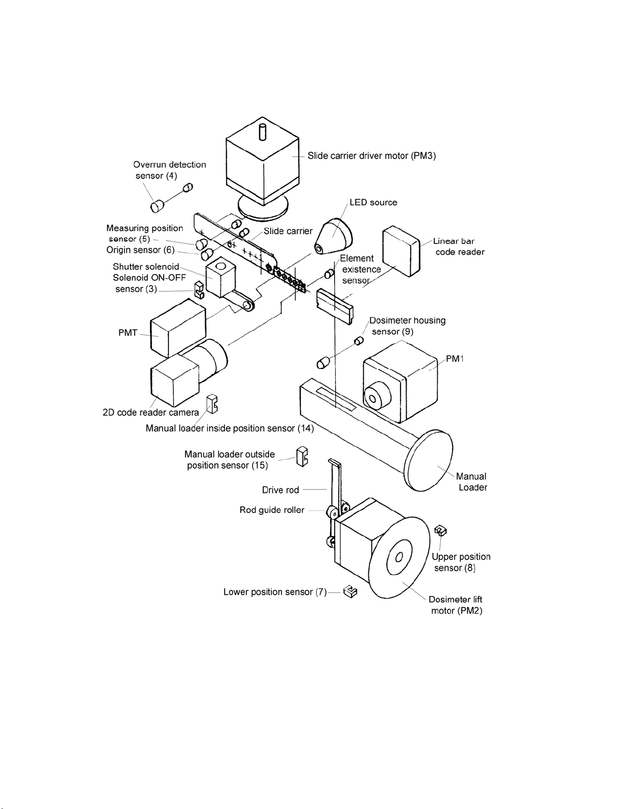
2.2 Structure of Measuring Block
Automatic Readers
InLight™ Systems Reader Service Manual
4
Manual Reader
InLight™ Systems Reader Service Manual
5

InLight™ Systems Reader Service Manual
Measuring Block Sensor Descriptions
Sensor
RSR
No.
1 1 116 2DCR_RDY 2D code reader is ready. OFF
2 2 115 2DCR_ERR 2D code reader error. OFF
3 3 114 Shutter solenoid on/off When solenoid is energized, LED is off. ON
4 4 113 Overrun position of carrier When slide carrier overruns, this is off. OFF
5 5 112 Measurement position of carrier
6 6 111 Origin position of carrier
7 7 110 Lower position of dosimeter
8 8 19 Upper position of dosimeter
9 9 18 Existence of dosimeter
10 10 17
11 11 16
12 12 15
13 13 14
14 14
15 15
16 16 11 Magazine head
LED
No.
Signal Name
PC No.
13
13
12
12 Automatic Reader: magazine end
Manual Reader: inside position of
manual loader
Automatic Reader: magazine slot
position
Manual Reader: outside position
of manual loader
Function Description
When measuring E1, E2, E3 or E4, this is
on.
When slide carrier stops at the origin
position, this is on.
When the dosimeter stops at the lower
position, this is on.
When the dosimeter stops at the upper
position, this is on.
When checking for dosimeter, this is off if
the dosimeter exists.
When the manual loader is pushed in, this
is off.
When the dosimeter is in measuring
position, this is on.
When the manual loader is pushed out,
this is off.
When the sensor detects end of
magazine, this is on.
When the sensor detects head of the
magazine, this is off.
LED
Active
State
ON
ON
ON
ON
OFF
OFF
ON
OFF
ON
OFF
LED1-16: on PCB (UDP516003A)
LEDs
6
 Loading...