

Page 1
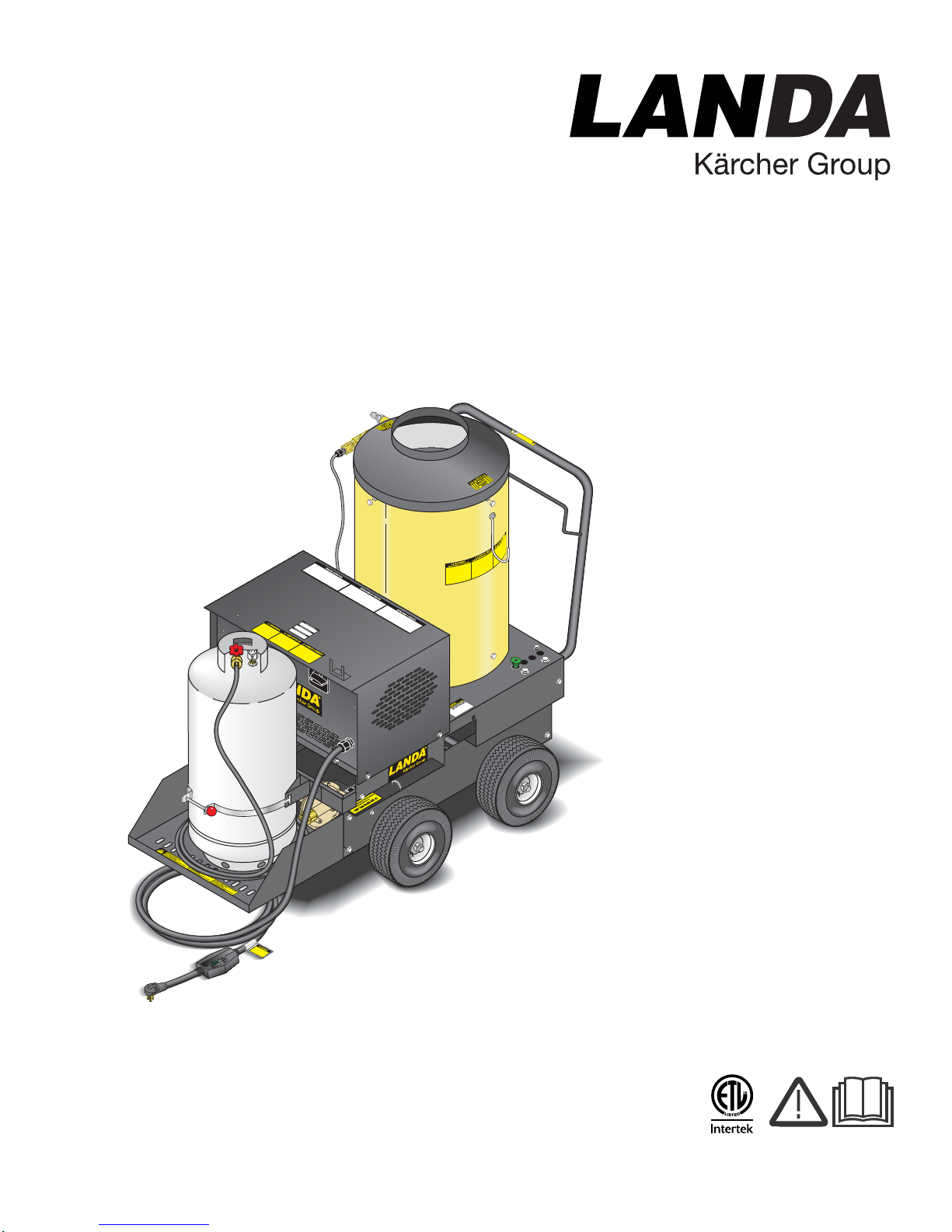
VHP Series
W
ARNIN
G
Tip
o
ver Hazza
r
d
®
Hot Water - Electric Powered - LP Gas Heated
Operator’s Manual
USE VAPOR FUEL ONLY
Pressure Washer
MODELS: VHP2-1500
1.109-556.0
VHP3-2000
1.109-557.0
For the Landa Dealer nearest
you, consult our web page at
www.landa.com
8.913-949.0-T 06/06/17
Page 2
Machine Data Label
2 Landa VHP 2-1500 / 3-2000 Operator’s Manual 8.913-949 .0 - T
Page 3

Table of Contents
Machine Data Label. . . . . . . . . . . . . . . . . . . . . . . . . .2
Table of Contents . . . . . . . . . . . . . . . . . . . . . . . . . . .3
How To Use This Manual . . . . . . . . . . . . . . . . . . . . .4
Safety
Introduction & Safety Information . . . . . . . . . . . . . . .5
Important Safety Information. . . . . . . . . . . . . . . . . . .6
Propane Tank Safety Instructions. . . . . . . . . . . . . . .9
Operations
Installation. . . . . . . . . . . . . . . . . . . . . . . . . . . . . . . .11
Check Water Heater Coil For Leaks . . . . . . . . . . . .13
Instructions for lighting . . . . . . . . . . . . . . . . . . . . . .13
WHAT TO DO IF YOU SMELL GAS. . . . . . . . . . . .13
Assembly Instructions. . . . . . . . . . . . . . . . . . . . . . .14
Operating Instructions. . . . . . . . . . . . . . . . . . . . . . .15
Detergents & General Cleaning Techniques . . . . .17
Maintenance
Shutting Down And
Clean-up . . . . . . . . . . . . . . . . . . . . . . . . . . . . . . .18
Storage . . . . . . . . . . . . . . . . . . . . . . . . . . . . . . . . . .19
After Extended Storage. . . . . . . . . . . . . . . . . . . . . .19
Engine Maintenance. . . . . . . . . . . . . . . . . . . . . . . .19
Preventative Maintenance . . . . . . . . . . . . . . . . . . .19
Maintenance And Service. . . . . . . . . . . . . . . . . . . .20
Unloader Valves . . . . . . . . . . . . . . . . . . . . . . . . . . .20
Winterizing Procedure. . . . . . . . . . . . . . . . . . . . . . .20
High Limit Hot Water Thermostat . . . . . . . . . . . . . .20
Pumps. . . . . . . . . . . . . . . . . . . . . . . . . . . . . . . . . . .20
Cleaning of Coils. . . . . . . . . . . . . . . . . . . . . . . . . . .20
Removal of Soot and Heating Coil . . . . . . . . . . . . .20
Pressure Relief Valve . . . . . . . . . . . . . . . . . . . . . . .21
Rupture Disk. . . . . . . . . . . . . . . . . . . . . . . . . . . . . .21
Propane Cylinder Capacity. . . . . . . . . . . . . . . . . . .21
Oil Change Record . . . . . . . . . . . . . . . . . . . . . . . . .22
Troubleshooting . . . . . . . . . . . . . . . . . . . . . . . . . . .23
Mantenimiento Y Servicio . . . . . . . . . . . . . . . . . . . .45
Identificacion de Componentes. . . . . . . . . . . . . . . .48
Parts
Landa VHP Left. . . . . . . . . . . . . . . . . . . . . . . . . . . 26
Landa VHP Right . . . . . . . . . . . . . . . . . . . . . . . . . 27
Hose & Spray Gun . . . . . . . . . . . . . . . . . . . . . . . . 32
LB Series Pump . . . . . . . . . . . . . . . . . . . . . . . . . . 34
VRT3 Unloader. . . . . . . . . . . . . . . . . . . . . . . . . . . 36
Injector Assembly #2 - 4 - 011182 . . . . . . . . . . . . 38
Spanish
Seguridad De La Maquina . . . . . . . . . . . . . . . . . . .40
Instalacion. . . . . . . . . . . . . . . . . . . . . . . . . . . . . . . .42
Instrucciones De Operacion . . . . . . . . . . . . . . . . . .44
Landa VHP 2-1500 / 3-2000 Operator’s Manual 8.913-949 .0 - T
3
Page 4

How To Use This Manual
Model:
Date of Purchase:
Serial Number:
Dealer:
Address:
Phone Number:
Sales Representative:
This manual contains the following sections:
• How to Use This Manual
•Safety
• Operations
• Maintenance
• Parts List
• Spanish
The HOW TO USE THIS MANUAL section will tell you
how to find important information for ordering correct
repair parts.
Parts may be ordered from authorized dealers. When
placing an order for parts, the machine model and
machine serial number are important. Refer to the
MACHINE DATA box which is filled out during the
installation of your machine. The MACHINE DATA box
is located on the inside of the front cover of this manual.
The model and serial number will be found on a decal
attached to the pressure washer.
The SAFETY section contains important information
regarding hazardous or unsafe practices of the
machine. Levels of hazards are identified that could
result in product damage, personal injury, or severe
injury resulting in death.
The OPERATIONS section is to familiarize the operator
with the operation and function of the machine.
The MAINTENANCE section contains preventive maintenance to keep the machine and its components in
good working condition. They are listed in this general
order:
• Storage
• After Extended Storage
• Engine Maintenance
• Preventative Maintenance
• Unloader Valves
• Winterizing Procedure
• High Limit Hot Water Thermostat
• Pumps
• Cleaning of Coils
• Removal of Soot and Heating Coil
• Rupture Disk
• Propane Cylinder Capacity
• Oil Change Record
• Troubleshooting
The PARTS LIST section contains assembled parts
illustrations and corresponding parts list. The parts lists
include a number of columns of information:
4
Landa VHP 2-1500 / 3-2000 Operator’s Manual 8.913-949 .0 - T
• REF – column refers to the reference number
on the parts illustration.
• PART NO. – column lists the part number for
the part.
• QTY – column lists the quantity of the part used
in that area of the machine.
• DESCRIPTION – column is a brief description
of the part.
• NOTES – column for information not noted by
the other columns.
NOTE: If a service or option kit is installed on your
machine, be sure to keep the KIT INSTRUCTIONS
which came with the kit. It contains replacement parts
numbers needed for ordering future parts.
NOTE: The manual part number is located on the
lower right corner of the front cover.
Page 5

Introduction & Safety Information
Thank you for purchasing this Pressure Washer. We
reserve the right to make changes at any time
without incurring any obligation.
Owner/User Responsibility:
The owner and/or user must have an understanding of
the manufacturer’s operating instructions and warnings
before using this pressure washer. Warning information
should be emphasized and understood. If the operator
is not fluent in English, the manufacturer’s instructions
and warnings shall be read to and discussed with the
operator in the operator’s native language by the
purchaser/owner, making sure that the operator
comprehends its contents.
Owner and/or user must study and maintain for future
reference the manufacturers’ instructions.
The operator must know how to stop the machine
quickly and understand the operation of all controls.
Never permit anyone to operate the engine without
proper instructions.
Safety
SAVE THESE INSTRUCTIONS
This manual should be considered a permanent
part of the machine and should remain with it if
machine is resold.
When ordering parts, please spec if y mo de l and
serial number. Use only identical replacement
parts.
This machine is to be used only by trained operators.
Landa VHP 2-1500 / 3-2000 Operator’s Manual 8.913-949 .0 - T
5
Page 6
Safety
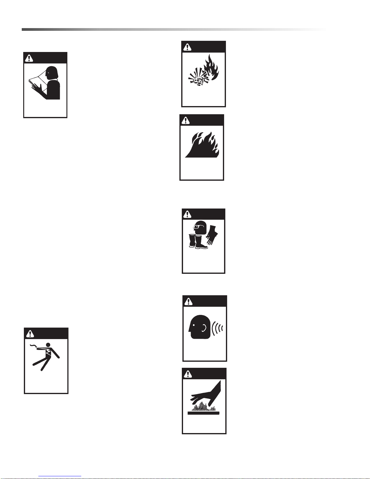
WARNING
READ OPERATOR’S
MANUAL THOROUGHLY
PRIOR TO USE.
OPERATIONS
SAFETY
MAINTENANCE
KEEP WATER
SPRAY AWAY FROM
ELECTRICAL WIRING.
WARNING
WARNING
RISK OF EXPLOSION:
IF GAS SMELL
PRESENT TURN OFF
SUPPLY
WARNING
USE PROTECTIVE
EYE WEAR
AND CLOTHING
WHEN OPERATING
THIS EQUIPMENT.
WARNING
EAR PROTECTION
MUST BE WORN
CAUTION
HOT DISCHARGE FLUID:
DO NOT TOUCH OR
DIRECT DISCHARGE
STEAM AT PERSONS.
WARNING
RISK OF FIRE.
DO NOT ADD FUEL
WHEN OPERATING
MACHINE.
Important Safety Information
WARNING: To reduce the risk of
injury, read operating instructions
carefully before using.
1. Read the owner's manual thoroughly. Failure to follow instructions could cause malfunction of
the machine and result in death,
serious bodily injury and/or
property damage.
2. Know how to stop the machine and bleed pressure
quickly. Be thoroughly familiar with the controls.
3. Stay alert — watch what you are doing.
4. Do not replace LP tank while machine is running.
5. All installations must comply with local codes.
Contact your electrician, plumber, utility company
or the selling dealer for specific details. If your
machine is rated 250 volts or less, single phase a
ground fault circuit interrupter (GFCI) will be
provided. If rated more than 250 volts, or more
than single phase this product should only be
connected to a power supply protected by a GF CI.
WARNING: Must be plugged into properly wired
three hole grounded outlet that accommodates
plug on power cord. Failure to comply could result
in electrical shock.
DANGER: Improper connection of the equipmentgrounding conductor can result in a risk of electrocution. Check with a qualified electrician or service
personnel if you are in doubt as to whether the
outlet is properly grounded. Do not modify the plug
provided with the product - if it will not fit the outlet,
have a proper outlet installed by a qualified electrician. Do not use any type of adaptor with this
product.
WARNING: Flammable liquids
can create fumes which can
ignite, causing property damage
or severe injury.
WARNING: Risk of explosion —
Operate only where open flame or
torch is permitted.
WARNING: Risk of fire — Do not
change tanks when the product is
operating or still hot.
WARNING: Use vapor fuel only.
7. Oil burning appliances shall be
installed only in locations where
combustible dusts and
flammable gases or vapors
not present. Do not store or use
gasoline near this machine
.
8. Keep operating area clear of all persons.
WARNING: High pressure spray
can cause paint chips or other
particles to become airborne and
fly at high speeds. To avoid
personal injury, eye, hand and
foot safety devices must be worn.
9. Always wear properly rated eye
protection such as safety
goggles or face shield while
spraying.
(Safety glasses do not provide full protection.)
WARNING: This machine
exceeds 85 db appropriate ear
protection must be worn.
are
WARNING: Keep wand, hose, and
water spray away from electric
wiring or fatal electric shock may
result.
6. To protect the operator from
electrical shock, the machine
must be electrically grounded. It
is the responsibility of the owner
to connect this machine to a UL
grounded receptacle of proper
voltage and amperage ratings. Do not spray water
on or near electrical components. Do not touch
machine with wet hands or while standing in water.
Always disconnect power before servicing.
6
Landa VHP 2-1500 / 3-2000 Operator’s Manual 8.913-949 .0 - T
CAUTION: Hot discharge fluid.
Do not touch or direct discharge
stream at persons or animals.
WARNING: This machine
produces hot water and must
have insulated components
attached to protect the operator.
Page 7
Safety
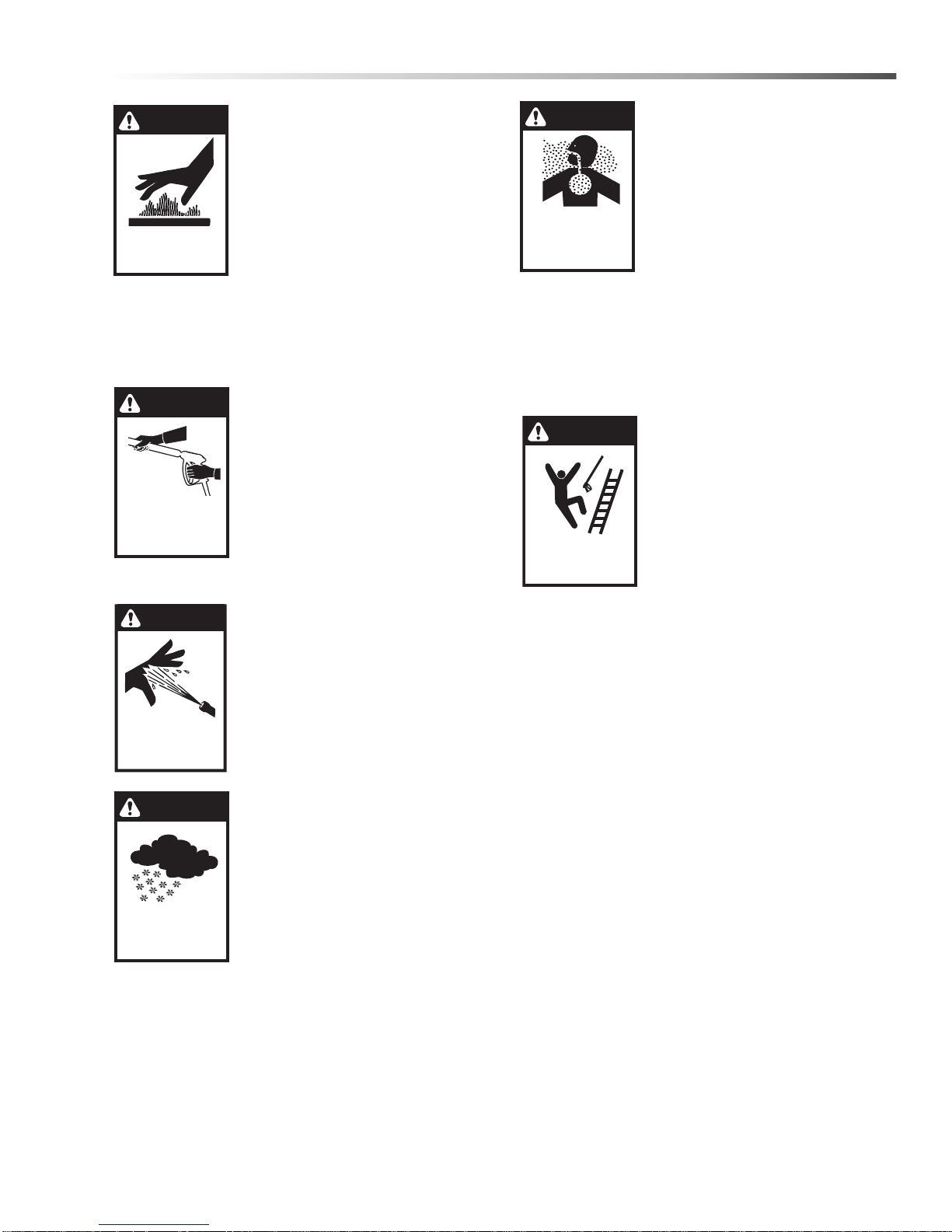
WARNING
RISK OF INJURY.
HOT SURFACES
CAN CAUSE BURNS
WARNING
TRIGGER GUN KICKS
BACK — HOLD WITH
BOTH HANDS
WARNING
RISK OF INJECTION
OR SEVERE INJURY
TO PERSONS. KEEP
CLEAR OF NOZZLE.
WARNING
PROCTECT FROM
FREEZING
WARNING
RISK OF INJURY
FROM FALLS WHEN
USING LADDER.
DANGER
RISK OF
ASPHYXIATION.
USE THIS PRODUCT
ONLY IN A WELL
VENTILATED AREA.
WARNING: Risk of injury. Hot
surfaces can cause burns. Use
only designated gripping areas of
spray gun and wand. Do not place
hands or feet on non-insulated
areas of the pressure washer.
10. To reduce the risk of injury, close supervision is
necessary when a machine is used near children.
Do not allow children to operate the pressure
washer. This machine must be attended during
operation.
WARNING: Grip cleaning wand
securely with both hands before
starting. Failure to do this could
result in injury from a whipping
wand.
11. Never make adjustments on
machine while in operation.
12. Be certain all quick coupler
fittings are secured before using
pressure washer.
WARNING: High pressure
developed by these machines will
cause personal injury or
equipment damage. Keep clear of
nozzle. Use caution when operating. Do not direct discharge
stream at people and animals, or
severe injury or death will result.
WARNING: Protect machine from
freezing.
13. To keep machine in best
operating conditions, it is
important you protect machine
from freezing. Failure to protect
machine from freezing could
cause malfunction of the
machine and result in death,
serious bodily injury, and/or
property damage. Follow storage instructions
specified in this manual.
14. Inlet water must be clean fresh water and no hotter
then 90°F.
DANGER: Risk of asphyxiation.
Use this product only in a well
ventilated area.
15. Running this product indoors
can result in death due to
carbon monoxide, a poison gas
you cannot see or smell. Only
use outdoors and far away from
windows, doors and openings or
vents.
16. Manufacturer will not be liable for any changes
made to our standard machines or any components not purchased from us.
17. The best insurance against an accident is precaution and knowledge of the machine.
WARNING: Be extremely careful
when using a ladder, scaffolding
or any other relatively unstable
location. The cleaning area
should have adequate slopes and
drainage to reduce the possibility
of a fall due to slippery surfaces.
18. Do not overreach or stand on unstable support.
Keep good footing and balance at all times.
19. Do not operate this machine when fatigued or
under the influence of alcohol, prescription medications, or drugs.
20. Follow the maintenance instructions specified in
the manual.
21. Do not replace LP tank while machine is running.
Serious injury could result.
WARNING: Use vapor fuel only.
22. The LP models are designed to run on vapor
propane fuel. Do not use liquid fuel. Have a
qualified serviceman install and service your equipment.
23. Never expose a spark or flame where there may be
unburned gas present.
24. Install the machine 18” above the floor and about 2
feet from wall providing adequate ventilation and
space.
25. When making repairs disconnect from electrical
source and shut off gas valve.
26. Install this machine on non combustible flooring.
Landa VHP 2-1500 / 3-2000 Operator’s Manual 8.913-949 .0 - T
7
Page 8
Safety
WARNING
DO NOT SPRAY
MACHINE OR ANY
PEOPLE, ANIMALS OR
ELECTRICAL PARTS.
WARNING
NOT SUITABLE
FOR CONNECTION
TO THE POTABLE
WATER MAINS.
27. Do not allow acids, caustic or abrasive fluids to
pass through the pump.
28. Never run pump dry or leave spray gun closed
longer than 1-2 minutes.
WARNING: If connection is made
to potable water supply, a back
flow device must be provided.
WARNING: Do not spray machine
or any people, animals or electrical parts.
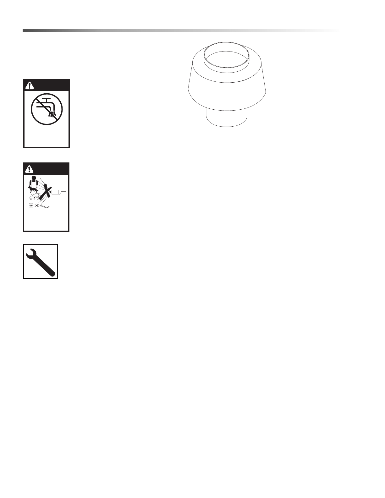
Example Of Down
Draft Diverter For Gas
Fired Machines
Follow the maintenance instructions
specified in the manual.
8
Landa VHP 2-1500 / 3-2000 Operator’s Manual 8.913-949 .0 - T
Page 9

Safety
Propane Tank Safety Instructions
Caution: Only qualified persons should fill your LP-Gas containers.
1. Never allow your LP-gas container to be filled above the maximum safe level as indicated by a scale or the
fixed liquid level gauge (outage). Do not use the visible gauge for filling.
2. Do not use a wrench or pliers to close the service valve or fixed liquid level gauge . T hese valve s are desig ned
to be closed leak-tight by hand or screwdriver as appropriate. If wrenches are necessary to stop a leak, the
valve needs repair or replacement.
3. When tightening the POL Nut (left hand thread) on the service valve, draw it up snug with a proper wrench.
This is a machined male brass fitting which seats securely against a female seat in the POL valve – no pipe
dope is necessary. Acme/Type 1 valves have right handed threads which are secure when hand tight, and on
the Quick Disconnect/Type 2 Valves, the male connection is inserted into the female connection on the cylinder
valve. (No wrenches required for both the Acme and the Quick Disconnect.)
4. When using container, slowly open service valve all the way. Listen to the regulator. A continuous hiss may
indicate a leak or an open valve on an appliance.
5. Check all tank and the line connections periodically to be sure they are tight. When testing for leaks, use
approved leak detector solution – not matches.
6. Make certain your container is properly fastened in place.
7. Turn container with open part of contain e r guar d to war d s fra me. Th is pr ot ects valves and regulator against
flying rocks and mud. Transport container in the proper position in which it is used, with the valves closed and
POL Plugs inserted for POL Valves or Dust Caps for Acme Valves. Secure the tank against falling or rolling.
8. Check for leaks after connecting. Apply approved leak detector solution to connection, turn off all burners and
pilots, and open service valve. Leaks will be detected by the growth of the bubbles. If bubbles grow, tighten or
repair the connection as needed. Repeat leak test until problem is corrected.
9. LP-gas is normally non-corrosive – you need not worr y about the inside of your container. However, the outside
should be kept free from rust by a periodic coat of paint in a light reflective color. It is very important to inspect
and maintain the bottom and foot ring on the container.
10. Do not store LP-gas containers indoors or in enclosed areas. Do not expose LP-gas container to heat. Always
store with service valve closed and plugged as required.
11. Do not attempt to repair any containers, container valves, regulator or appliances by yourself. Use only trained
certified LP-gas service personnel to perform repairs.
Propane tanks, gas bottles will not be picked up by local garbage collectors. Improper propane tank
disposal might be illegal in some areas. Propane tank disposa l is a safety issu e that is e asily handled by a
propane company.
Landa VHP 2-1500 / 3-2000 Operator’s Manual 8.913-949 .0 - T
9
Page 10
Operations
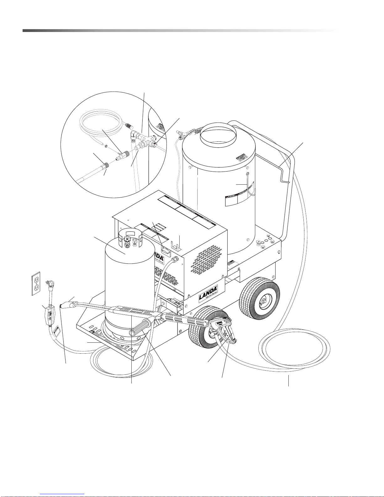
LP Tank
(not
included)
High Pressure
Hose Hanger
Wand
Holder
High
Pressure
Hose
Trigger
Spray Gun
Variable Pressure
Control Handle
Variable
Pressure
Wand
Brass Soap
Nozzle
GFCI
Propane
Hose
LP Shelf
Water Supply
(not included)
Pump &
Burner Switch
Wand
Rest
Discharge
Nipple
High Limit
Snap Switch
Quick
Coupler
Rupture
Disk
Collar
Detergent
Injector
Nozzle
Quick
Coupler
Reversed View
Component Identification
10
Landa VHP 2-1500 / 3-2000 Operator’s Manual 8.913-949 .0 - T
Page 11

Operations
Installation
WARNING: Moving this machine on an incline may
cause instability and could result in the machine
tipping over. Equipment damage or bodily harm
could occur.
Place machine in a convenient location providing
ample support, drainage and room for maintenance.
These machines are intended for indoor use.
Machine must be stored indoors when not in use.
Location
The location should protect the machine from
damaging environmental conditions, such as wind, rain
and freezing.
1. The machine should be run on a level surface
where it is not readily influenced by outside
sources such as strong winds, freezing temperatures, rain, etc. Consider accessibility for the
replacing of LP tanks, refilling of detergents, adjustments and maintenance when selecting a location.
Normal precautions should be taken by the
operator to prevent excess moisture from reaching
electrical components.
2. It is recommended that a partition be made
between the wash area and the machine to
prevent direct spray from the spray gun to come in
contact with machine. Excess moisture reaching
the electrical controls will reduce the machine life
and may cause electrical shorts.
3. During installation, beware of poorly ventilated
locations or areas where exhaust fans ma y cau se
an insufficient supply of oxygen. Sufficient combustion can only be obtained when there is a sufficient
supply of oxygen available for the amount of fuel
being burned. If it is necessary to install in a poorly
ventilated area, outside fresh air may have to be
piped to the burner and a fan installed to bring air
into the room. Avoid small locations or areas near
exhaust fans.
Gas Codes
Confer with local gas company and with proper
municipal officials regarding any specific code or regulations governing the installation. The installation must
conform to local codes.
Consult your local service dealer for high altitude
adjustments. In Canada, certification for installation at
altitudes over 4500 feet above sea level is the jurisdiction of local authorities. You should not readjust the
burner ring gas pressure. If you replace your g as valve,
you will need to adjust the new valve. Refer to your
machine’s specification plate for the correct pressure
setting. Follow the installation and adjustment instructions provided with your replacement valve.
NOTE: Air for combustion and ventilation along with
exhaust flue sizing must conform to methods outlined
in current American Standard (ANSI-Z223.1) National
Fuel Gas Code or National Standard of Canada CSA-
149.1 and CSA-149.2 “Installation Code for Gas
Burning Appliances”.
Electrical
This machine, when installed, must be electrically
grounded in accordance to local codes. Check for
proper power supply using a volt meter. The VHP215021D requires a 20 amp receptacle to comply with
UL 1776 certification standards.
Venting
Regulations or ventilation concerns may call for a
chimney or furnace pipe.When venting, if the machine
is to be in an enclosed area with a chimney on it, be
sure the chimney is the same size as the stack on the
machine. Poor draft will cause machine to soot and not
operate efficiently. When placing for installation, keep in
mind that the pressure washer should be positioned in
such a manner that the stack will be as straight as
possible and protrude through the roof of the building at
a proper location and at sufficient height to eliminate
downdraft. The chimney of gas fired machines should
be installed with a down draft diverter.
Draft Diverter
A draft diverter should be installed above the heat ing
coil. The diverter serves to sever the chimney effect
created in all sections of furnace pipe positioned below
to enhance the draft through the burner. It also helps
prevent freezing of the coil due to wind chill factors.
NOTE: The draft diverter is
not standard on VHP
machines.
The gas pressure coming out of the regulator and going
to the burner ring has been factory set for elevations of
0 to 2000 ft. Altitudes greater than 2000 ft will require
adjustments to the gas manifold pressures.
Landa VHP 2-1500 / 3-2000 Operator’s Manual 8.913-949 .0 - T
11
Page 12

Operations
When the pressure washer is installed in a tightly
closed room without ventilation openings to the
outdoors or other rooms, provisions shall be made for
supplying air for combustion through special openings,
one near the floor line and the other near the ceiling,
each to be sized on the basis of one square inch or
more of free area for each 1,000 BTU input per hour.
Placement
Do not locate near any combustible material. Keep all
flammable material at least 20 feet away.
Allow enough space for servicing the machine.
Local code will require certain distances from floor and
walls. (Two feet away should be adequate.)
Water Source
Water source for machine should be supplied by a 5/8"
I.D. garden hose with a city water pressure of not less
than 30 psi. If the water supply is inadequate, or if the
garden hose is kinked, the machine will run very rough
and the burner will not fire.
Connection
Connect the wand, nozzle, hose and spray gun (where
applicable). On pipe thread connections, use teflon
tape to avoid water leaks. (See Component Identification.)
Defective pipes or fittings should be replaced and not
repaired. Never use a flame or fire in any for m to locate
gas leaks, use a soap solution.
After the piping and meter have been checked
completely, purge the system of air. DO NOT bleed the
air inside an enclosed room.
The pressure washer and its individual shut-off valve
must be disconnected from the gas supply piping
system during the pressure testing of that system at
test pressure in excess of 1/2 psig or damage to the
gas valve will occur.
Shut-Off Valve
A gas shut-off valve has been installed between the
gas supply line and the washer. The plumbing also
includes a union between the shut-off valve and the
burner.
Condensation from Coils
When cold water is being pumped into the water heater
coils, and the burners are on, condensation will form on
the coils and drip down into the burner compartment
giving the appearance of a leaking coil, particularly on
cold humid days.
Attach high pressure hose to discharge nipple by
pulling the quick coupler collar back and inserting it
onto the discharge nipple. Then push the collar forward
to secure. A detergent injector could be inserted
between the hose coupler and the discha r ge nipp le .
(Assembly Instructions)
Place detergent dip tube into liquid soap or detergent
solution. Avoid letting tube suck air.
CAUTION: When installing propane hose to LP
tank, please note that it has left hand threads.
Inspection and Testing
Before turning gas under pressure into piping, all
openings from which gas can escape should be closed.
Immediately after turning on gas, the system should be
checked for leaks. This can be done by watching the 1/
2 cubic foot test dial and allowing 5 minutes to show
any movement, or by soaping each pipe connection
and watching for bubbles. If a leak is found, make the
necessary repairs and repeat the above test.
12
Landa VHP 2-1500 / 3-2000 Operator’s Manual 8.913-949 .0 - T
Page 13
Operations
WARNING
RISK OF FIRE OR
EXPLOSION:
FOLLOW
INSTRUCTIONS
EXACTLY
Check Water Heater Coil For Leaks
With the burner “OFF” start the pumping machine and
allow to run for a few minutes. Look into the burner
compartment with a drop light or flashlight. If no leak is
visible, then subsequent water dripping from the coil
will be from condensation in the flue gases when the
burner is on, as described in the previous paragraph.
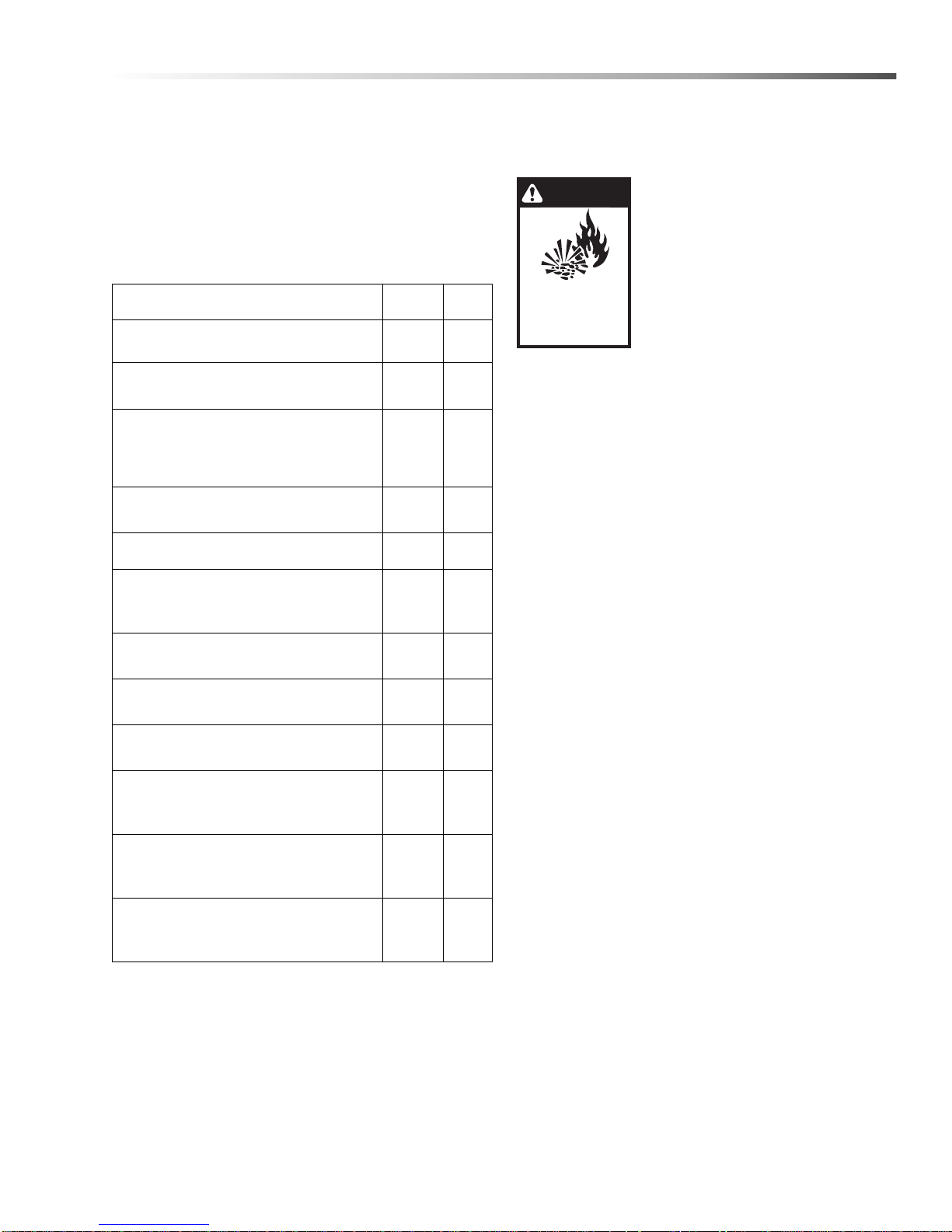
PRE-START CHECK LIST YES NO
Is machine protected from downdraft
and excessive wind?
Is machine shielded from moisture or
water spray?
Is the voltage correct and circuit
breaker and supply cord adequate
according to specifications and
serial plate notation?
Is the machine electrically
grounded?
Is there ample water supply?
Have all flammable liquids or gases
been removed from installation
location?
Is the machine properly vented to
allow adequate air flow?
Is there an adequate gas supply for
the BTU rating of the burner?
Have gas lines been checked for gas
leaks?
Have all operators using this
machine been instructed properly
& have they read the manual?
Has the machine been installed
according to the instructions in the
operator's manual?
Is the incoming gas supply pressure to
the machine between 6-14 water
column inches or 1/2 psig?
Instructions for lighting
WARNING: If “NO” has been checked on any of the
above questions, do not operate.
WARNING: If you do not follow
instructions exactly, a fire or
explosion may result causing
property damage, personal injury
or loss of life.
1. This machine has a pilot which
must be lighted by hand. When
lighting the pilot, follow these
instructions exactly.
2. BEFORE LIGHTING smell all around the
appliance area for gas. Be sure to smell next to the
floor because propane gas is heavier than air and
will settle on the floor.
For your safety:
WHAT TO DO IF YOU SMELL GAS
a. Do not try to light any appliance.
b. Do not touch any electrical switch; do not use
any phone in your building.
c. Immediately call your gas supplier from a neigh-
bor’s phone. Follow the gas supplier’s instructions.
d. If you cannot reach your gas supplier, call the
fire department.
3. Use only your hand to push in or turn gas control
knob. Never use tools. If the knob will not push in
or turn by hand, don’t try to repair it, call a qualified
service technician. Force or attempted repair may
result in a fire or explosion.
4. Do not use this machine if any part has been u nder
water. Immediately call a qualified service technician to inspect the machine and to replace any part
of the control system or any gas control that has
been under water.
Landa VHP 2-1500 / 3-2000 Operator’s Manual 8.913-949 .0 - T
13
Page 14
Operations
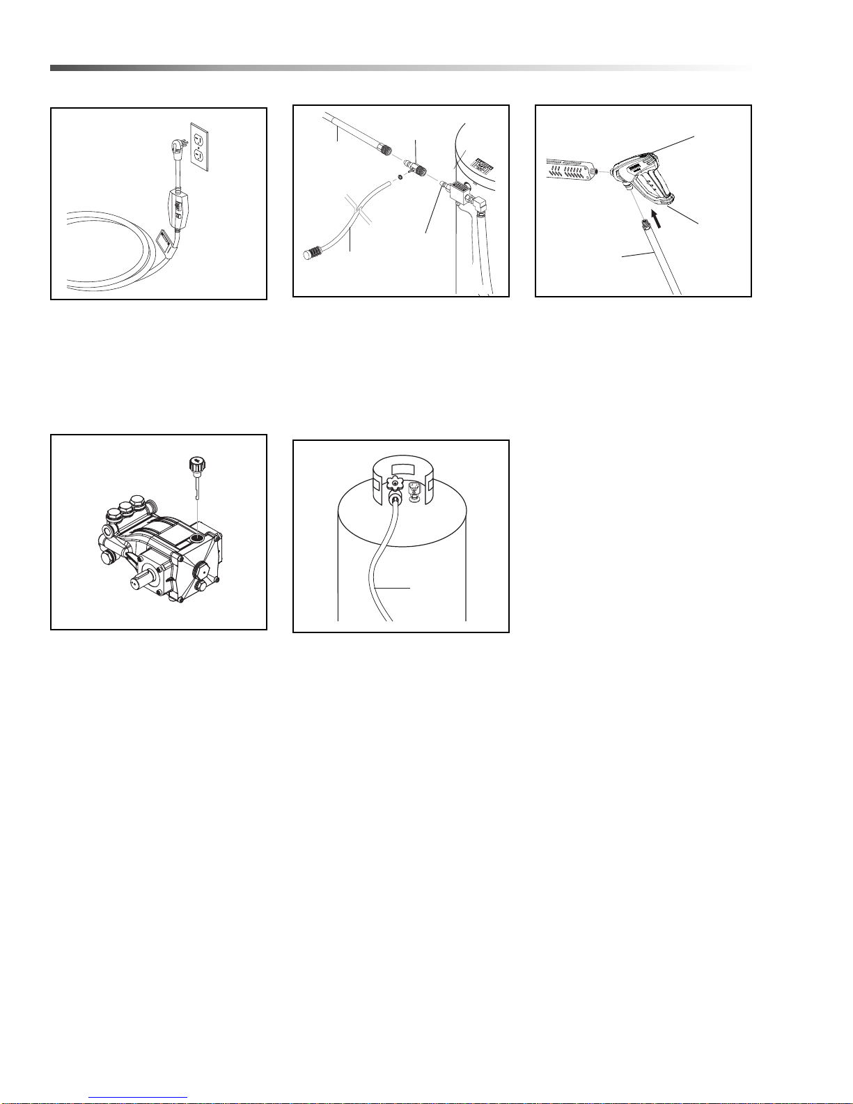
Safety
Latch
High
Pressure
Hose
Spray
Gun
Detergent
Injector
High
Pressure
Hose
Discharge
Nipple
Detergent
Suction
Tube
Propane
Hose
Safety
Latch
Spray
Gun
High Pressure
Hose
Assembly Instructions
STEP 1: Connect power cord to
proper electrical outlet according to
serial plate information. Push in
GFCI reset button. The VHP215021D requires a 20 amp receptacle.
STEP 4: Check oil level by using
supplied dip-stick. Use SAE 10W40 non-detergent only.
STEP 2: Connect high pressure
hose to discharge nipple by sliding
quick coupler collar back. (If
detergent is to be applied, insert a
detergent injector.) Insert quick
coupler onto discharge nipple and
secure by pushing quick coupler
collar forward.
STEP 5: Connect propane hose to
a propane tank.
STEP 3: Attach the high pressure
hose to the spray gun using teflon
tape on hose threads. Move safety
latch into locked position.
14
Landa VHP 2-1500 / 3-2000 Operator’s Manual 8.913-949 .0 - T
Page 15
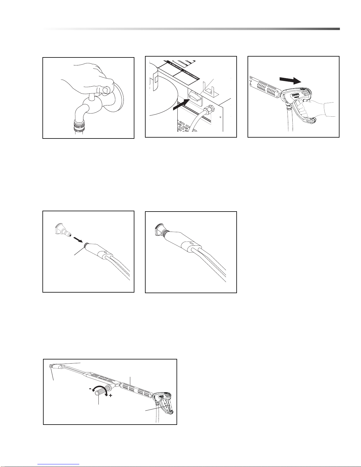
Operating Instructions
Coupler
Collar
Turn Pump/
Burner
Switch Off
Variable Pressure
Control Handle
Trigger
Variable Pressure
Wand (VP)
High
Pressure
Nozzle
Brass Soap
Nozzle
Operations
STEP 1: STOP! Read operator’s
manual before operating this
machine. Failure to read operation
and warning instructions may result
in personal injury or property
damage. Connect water supply
hose to inlet connector and turn
water on.
STEP 4: Pull the spring-loaded
collar of the wand coupler collar
back to insert your choice of
pressure nozzle. CAUTION: Never
replace nozzles without
engaging the safety latch on th e
spray gun trigger.
STEP 2: Turn all switches off.
Remove and position LP tank as far
from machine as supply hose will
allow.
STEP 5: Release the coupler collar
and push the nozzle until the collar
clicks. Pull the nozzle to make sure
it is seated properly.
STEP 3: Before installing nozzle,
Pull trigger on spray gun allowing
water to flow until all air has been
discharged from the system. Check
for water leaks and tighten as
needed.
Grip spray gun variable pressure
wand securely. Then turn the
variable pressure control handle
counterclockwise to flush any
debris out of soap nozzle.
.
Landa VHP 2-1500 / 3-2000 Operator’s Manual 8.913-949 .0 - T
STEP 6: Selection of high or low pressure is accompanied
by turning the handle.
NOTE: High pressure nozzle must be inserted at end of
wand to obtain high pressure. To apply soap read
operator's manual.
15
Page 16
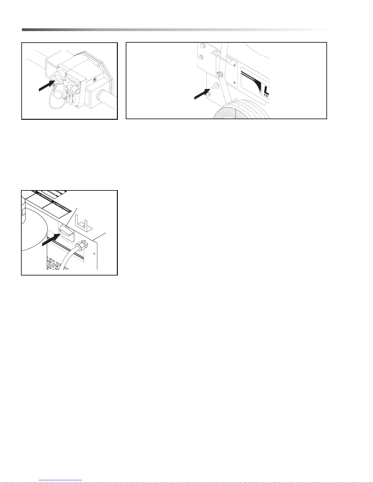
Operations
Control
Knob
Gas
Valve
Red
Ignitor
Pump and Burner
Switch
STEP 7: Open valve on LP tank,
then slightly depress main gas
valve control knob on the right side
of the machine and turn it counterclockwise to the Pilot position.
NOTE: Knob cannot be turned
from “Pilot” to “OFF” unless the
knob is slightly depressed.
STEP 9: Turn switch to pump
position and pull the trigger on the
spray gun. Turn variable pressure
control wand handle clockwise to
obtain pressure for cold water operation.
STEP 8: Depress the control knob all the way and hold it in. After five (5)
seconds, depress the red igniter until you hear a loud click. Repeat 3 or 4
times if necessary until pilot is lit. If pilot does not remain lit, repeat
operation allowing a longer period of time before releasing the gas valve
knob. After the pilot lights, continue to hold the control knob down for about
one (1) minute before releasing. Look at the pilot viewing mirror at the rear
of the machine.
Turn gas control knob counterclockwise to “ON.”
For hot water, turn the switch to the
burner position and pull the trigger
on the spray gun.To apply detergent, read section on Detergents
and General Cleaning Techniques
16
Landa VHP 2-1500 / 3-2000 Operator’s Manual 8.913-949 .0 - T
Page 17
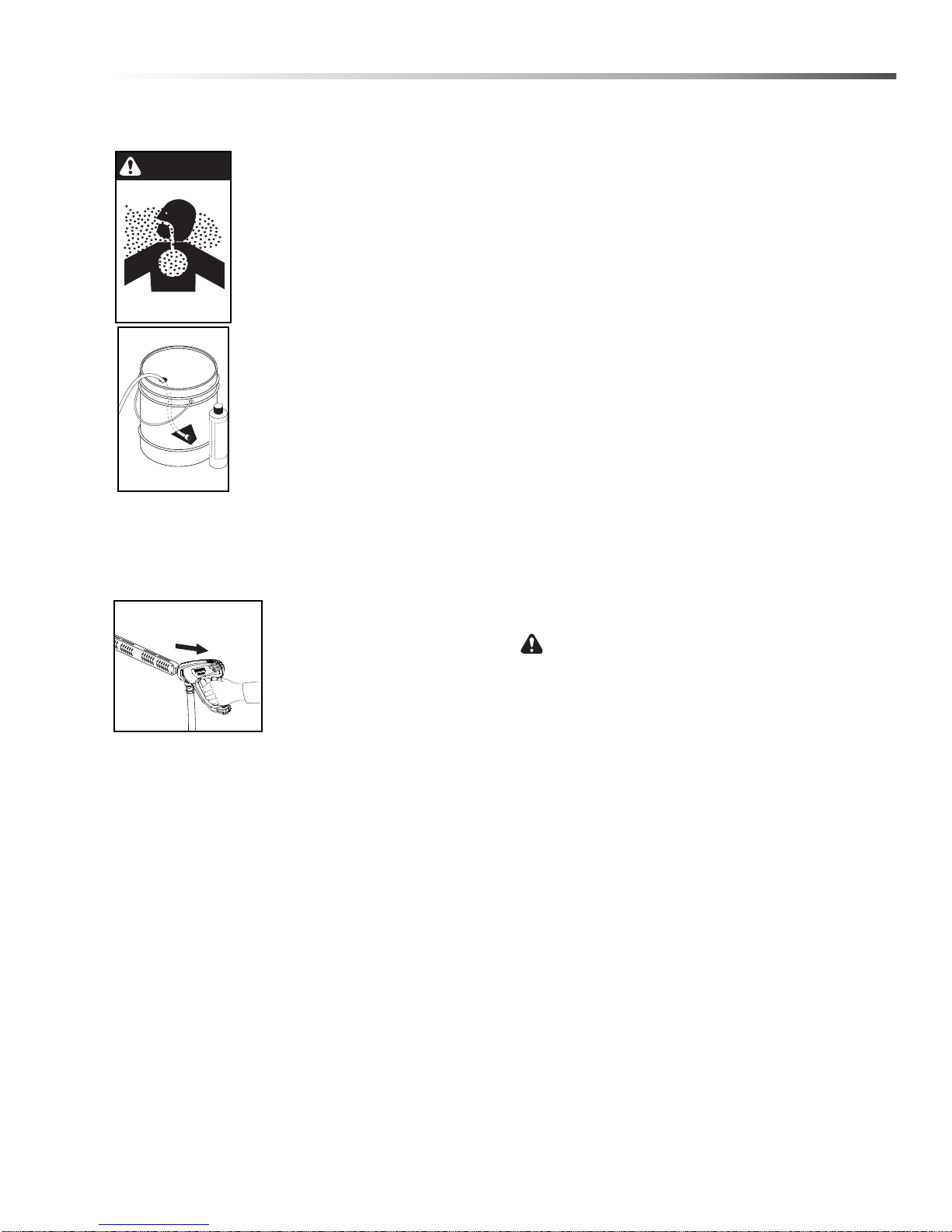
Operations
WARNING
Detergents & General Cleaning
Techniques
WARNING: Some detergents may
be harmful if inhaled or ingested,
causing severe nausea, fainting
or poisoning. The harmful
elements may cause property
damage or severe injury.
STEP 1: Use detergent designed
specifically for pressure washers.
Household detergents could damage
the pump. Prepare detergent
solution as required by the manufacturer. Fill a container with pressure
washer detergent. Place the filter
end of detergent suction tube into
the detergent container.
STEP 2: Apply safety latch to spray gun trigger.
NOTE: Detergent cannot be applied using the yellow
nozzle.
STEP 3: With the motor
running, pull trigger to operate
machine. Liquid detergent is
drawn into the machine and
mixed with water at an approximate ratio of 15 to 1. Turn
pressure control handle on
wand counterclockwise. This
lowers the pressure by directing the water flow th rough
the soap nozzle and allow detergent injector to siphon
soap.
Apply detergent to work area. Do not allow detergent to
dry on surface.
IMPORTANT: You must flush the detergent
injection system after each use by placing the
suction tube into a bucket of clean water, then run
the pressure washer in low pressure for 1-2
minutes.
Cleaning Tips
Pre-rinse cleaning surface with fresh water. Place
detergent suction tube directly into cleaning solution
and apply to surface at low pressure (for best results,
limit your work area to sections approximately 6 feet
square and always apply detergent from bo ttom to top).
Allow detergent to remain on surface 1-3 minutes. Do
not allow detergent to dry on surface. If surface
appears to be drying, simply wet down surface with
fresh water. If needed, use brush to remove stubborn
dirt. Rinse at high pressure from top to bottom in an
even sweeping motion keeping the spray nozzle
approximately 1 foot from cleaning surface. Use overlapping strokes as you clean and rinse any surface. For
best surface cleaning action, spray at a slight angle.
Recommendations:
• Before cleaning any surface, an inconspicuous
area should be cleaned to test spray pattern
and distance for maximum cleaning results.
• If painted surfaces are peeling or chipping, use
extreme caution as pressure washer may
remove the loose paint from the surface.
• Keep the spray nozzle a safe distance from the
surface you plan to clean. High pressure wash
a small area, then check the surface for
damage. If no damage is found, continue to
pressure washing.
CAUTION - Never use:
• Bleach, chlorine products and othe r co rro siv e
chemicals
• Liquids containing solvents (i.e., paint thinner,
gasoline, oils)
• Tri-sodium phosphate products
• Ammonia products
• Acid-based products
These chemicals will harm the machine and will
damage the surface being cleaned.
Rinsing
It will take a few seconds for the detergent to clear.
Apply safety latch to spray gun. Remove black soap
nozzle from the quick coupler. Select and install the
desired high pressure nozzle.
NOTE: You can also stop detergent from flowing by
simply removing detergent siphon tube from bottle.
Landa VHP 2-1500 / 3-2000 Operator’s Manual 8.913-949 .0 - T
17
Page 18
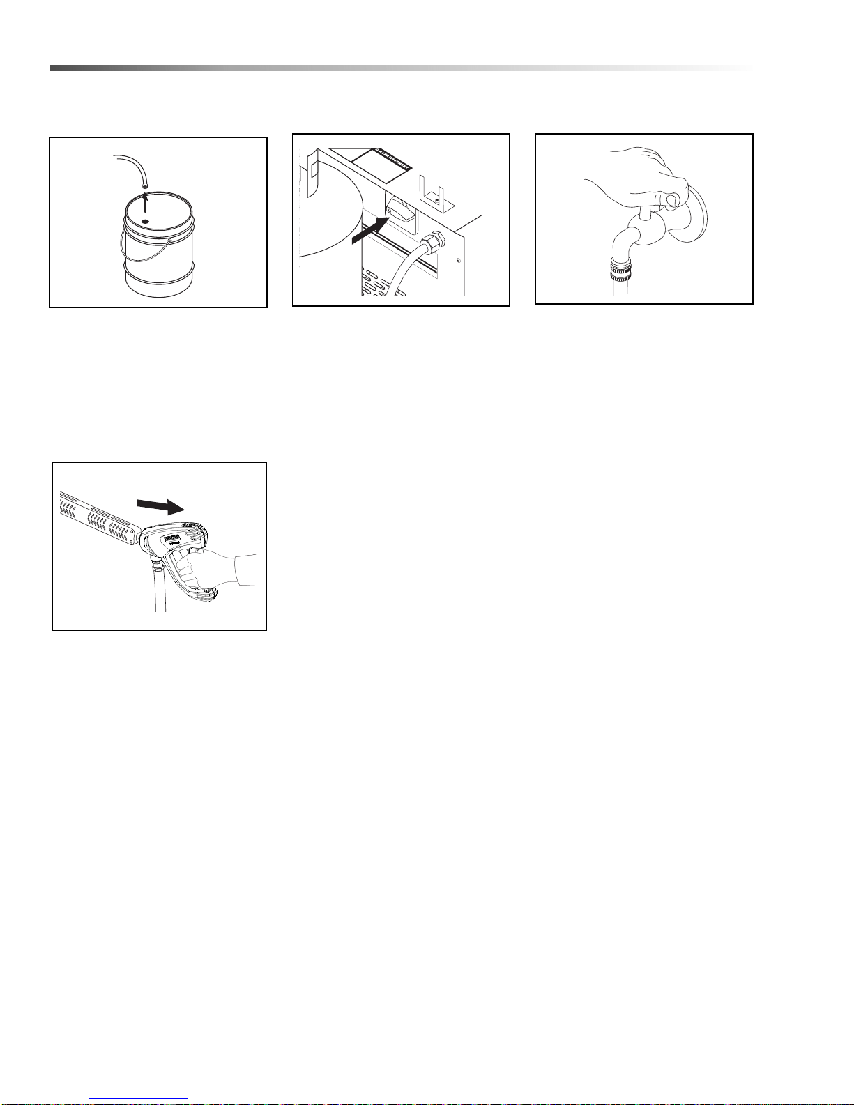
Pump Switch
Maintenance
Shutting Down And
Clean-up
STEP 1: Remove detergent suction
tube from container and insert into
one (1) gallon of fresh water. Flush
detergent lines with fresh water,
switch to the pump position and
continue to spray water allowing
burner to cool.
STEP 4: Squeeze trigger on spray
gun to relieve remaining pressure.
Move safety latch into its locked
position.
STEP 2: After water has cooled,
turn pump off. Turn main gas valve
off, then close the valve on the LP
tank. Secure the LP tank to the
machine when moving it.
STEP 3: Turn the water off. To
protect from freezing, pull the
trigger on spray gun to allow water
to drain from the system
18
Landa VHP 2-1500 / 3-2000 Operator’s Manual 8.913-949 .0 - T
Page 19

Maintenance
Storage
CAUTION: Always store your pressure washer in a
location where the temperature will not fall below
32°F (0°C). The pump in this machine is susceptible
to permanent damage if frozen. FREEZE DAMAGE
IS NOT COVERED BY WARRANTY.
1. Stop the pressure washer, squeeze spray gun
trigger to release pressure.
2.
Detach water supply hose and high pressure hose.
3. Turn on the machine for a few seconds, until
remaining water exits. Turn engine off immediately.
4. Drain the gas and oil from the engine.
5.
Do not allow high pressure hose to become kinked.
6. Store the machine and accessories in a room
which does not reach freezing temperatures.
CAUTION: Failure to follow the above directions
will result in damage to your pressure washer.
When the pressure washer is not being operated or is
being stored for more than one month, follow these
instructions:
1. Replenish engine oil to upper level.
2. Drain gasoline from fuel tank, fuel line, fuel valve
and carburetor.
3. Pour about one teaspoon of engine oil through the
spark plug hole, pull the starter grip several times
and replace the plug. Then pull the starter grip
slowly until you feel increased pressure which
indicates the piston is on its compression stroke
and leave it in that position. This closes both the
intake and exhaust valves to prevent rusting of
cylinder.
4. Cover the pressure washer and store in a clean,
dry place that is well ventilated away from open
flame or sparks. NOTE: The use of a fuel additive,
such as STA-BIL
the formulation of fuel deposits during shortage.
Such additives may be added to the gasoline in the
fuel tank of the engine, or to the gasoline in a
storage container.
®
, or an equivalent, will minimize
Engine Maintenance
During the winter months, rare atmospheric conditions
may develop which will cause an icing condition in the
carburetor. If this develops, the engine may run rough,
lose power and may stall. This temporary condition can
be overcome by deflecting some of the hot air from the
engine over the carburetor area.
NOTE: Refer to the engine manufacturer's manual for
service and maintenance of the engine.
Preventative Maintenance
1. Check to see that the water pump is properly
lubricated.
2. Follow winterizing instructions to prevent freeze
damage to the pump and coils.
3. Always neutralize and flush detergent from system
after use.
4. If water is known to be high in mineral content, use
a water softener in your water system or de-scale
as needed.
5. Do not allow acidic, caustic or abrasive fluids to be
pumped through system.
6. Always use high grade quality Landa cleaning
products.
7. Never run pump dry for extended perio ds
of time.
8. Periodically de-lime coils as per instructions.
It is advisable, periodically, to visually inspect the
burner. Check air inlet to make sure it is not clogged or
blocked. Wipe off any oil spills and keep this equipment
clean and dry.
The areas around the Landa washer should be kept
clean and free of combustible materials, gasoline and
other flammable vapors and liquids.
The flow of combustion and ventilating air to the burner
must not be blocked or obstructed in any manner.
After Extended Storage
CAUTION: Prior to restarting, thaw out any
possible ice from pressure washer hoses,
spray gun or wand.
Landa VHP 2-1500 / 3-2000 Operator’s Manual 8.913-949 .0 - T
19
Page 20

Maintenance
Maintenance And Service
Unloader Valves
Unloader valves relieve pressure in the line when the
shut-off spray gun is closed. Unloader valves are
preset and tested at the factory before shipping. Occasional adjustment of the unloader may be necessary to
maintain correct pressure. (Contact your local dealer
for correct procedure in adjusting unloader valve.)
Tampering with the factory setting may cause personal
injury and/or property damage, and will void the manufacturer's warranty.
Winterizing Procedure
Damage due to freezing is not covered by warranty.
Adhere to the following cold weather procedures
whenever the washer must be stored or operated
outdoors under freezing conditions.
During winter months, when temperatures drop below
32°F, protecting your machine against freezing is
necessary. Store the machine in a heated room. If this
is not possible then mix a 50/50 solution of anti-freeze/
water into a 5 gallon bucket and with a short section of
garden hose elevate the bucket and turn the pump on
to siphon the anti-freeze through the machine. If
compressed air is available, an air fitting can be
screwed into the inlet connector and, by injecting
compressed air, all water will be blown out of the
system.
Cleaning of Coils
In alkaline water areas, lime deposits can accumulate
rapidly inside the coil pipes. This growth is increased by
the extreme heat build up in the coil. The best prevention for liming conditions is to use high quality cleaning
detergents. In areas where alkaline water is an extreme
problem, periodic use of Landa Coil Descaler (part
#8.914-296.0) will remove lime and other deposits
before coil becomes plugged.
Periodic descaling of the heating coil is recommended so please consult your local Landa Dealer
for instructions.
Removal of Soot and Heating Coil
In the heating process, fuel residue in the form of soot
deposits may develop between the heating coil pipe
and block air flow which will affect burner combustion.
When soot has been detected on visual observation,
the soot on the coil must be washed off after following
the coil removal steps.
1. Remove the tank head assembly by unscrewing
the three Tek screws and lifting the tank head off.
2. Remove the two pipe nipples and associated
fittings.
3. Lift the coil out of the outer wrap.
CAUTION: The coil weighs about 80 lbs. Use proper
lifting techniques.
4. Clean, repair and replace the coil by reversing the
above steps.
High Limit Hot Water Thermostat
For safety, each machine is equipped with a high limit
control switch. In the event the temperature of the water
should exceed its operating temperature, the high limit
control will turn the burner off until the water cools.
Pumps
Use only SAE 10W-40 weight non-foaming oil. Change
oil after first 50 hours of use. Thereafter, change oil
every year or at 500 hour intervals. Oil level should be
checked through use of the dipstick found on the top of
the pump or by the red dot visible through the oil gauge
window. Oil should be maintained at that level.
20
Landa VHP 2-1500 / 3-2000 Operator’s Manual 8.913-949 .0 - T
Page 21

Maintenance
Pressure Relief Valve
Each machine is equipped with a relief valve to relieve
pressure in the system when higher than normal
operating pressures are encountered. Unusually high
pressures come from an object plugging the spray
nozzle. This problem can easily be remedied by
removing the obstruction. If operating pressure of
machine is found to be normal and relief valve
continues to leak, repair or replace the valve.
Rupture Disk
If pressure from pump or thermal expansion should
exceed safe limits, the rupture disk will burst, allowing
high pressure to be discharged through hose to ground.
When disk ruptures, it needs to be replaced.
Propane Cylinder Capacity
An important consideration with propane systems is the
capacity of the supply cylinder relative to the needs of
the burner. The burner operates on propane as a gas;
as gas is used from the propane cylinder, the liquid in
the cylinder boils to maintain gas pressure. This boiling
process cools the liquid, and in a heavy, continuousdemand situation, the liquid temperature can fall to the
point at which it cannot provide gas as rapidly as is
needed. In this case, it may be necessary to warm the
propane cylinder by directing a warm spray, not over
120° F, on the cold cylinder or by manifolding two
propane bottles together to increase total vaporization
capacity. It is recommended that a minimum 30 lb.
vapor propane bottle be used on the machine.
Landa VHP 2-1500 / 3-2000 Operator’s Manual 8.913-949 .0 - T
21
Page 22
Maintenance
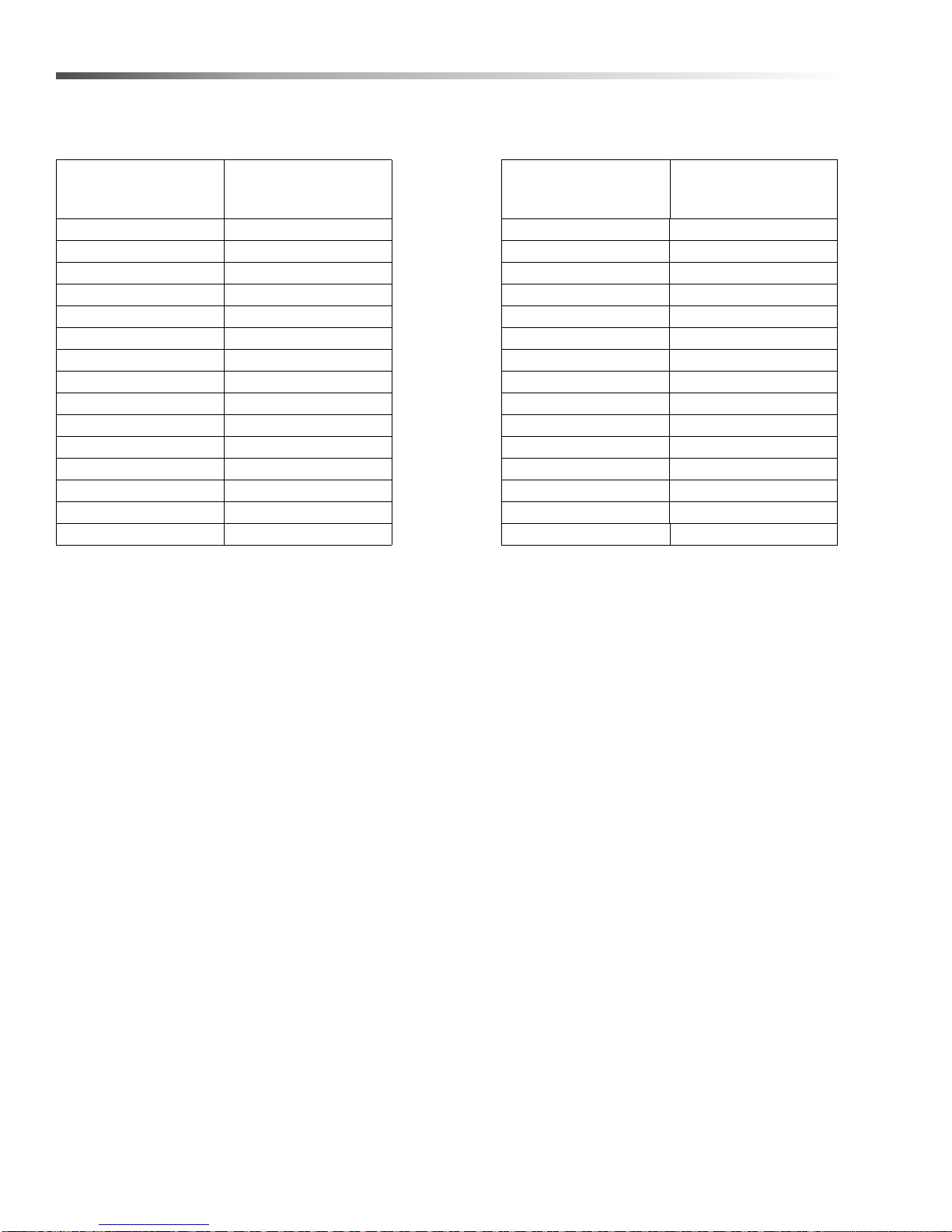
Oil Change Record
Pump Oil - SAE 10W-40 (Non-foaming)
D at e Oi l Ch a ng e d
Month/Day/Year
Estimated Operating
Hours Since Last Oil
Change
D at e Oi l Ch a ng e d
Month/Day/Year
Estimated Operating
Hours Since Last Oil
Change
22
Landa VHP 2-1500 / 3-2000 Operator’s Manual 8.913-949 .0 - T
Page 23
Troubleshooting
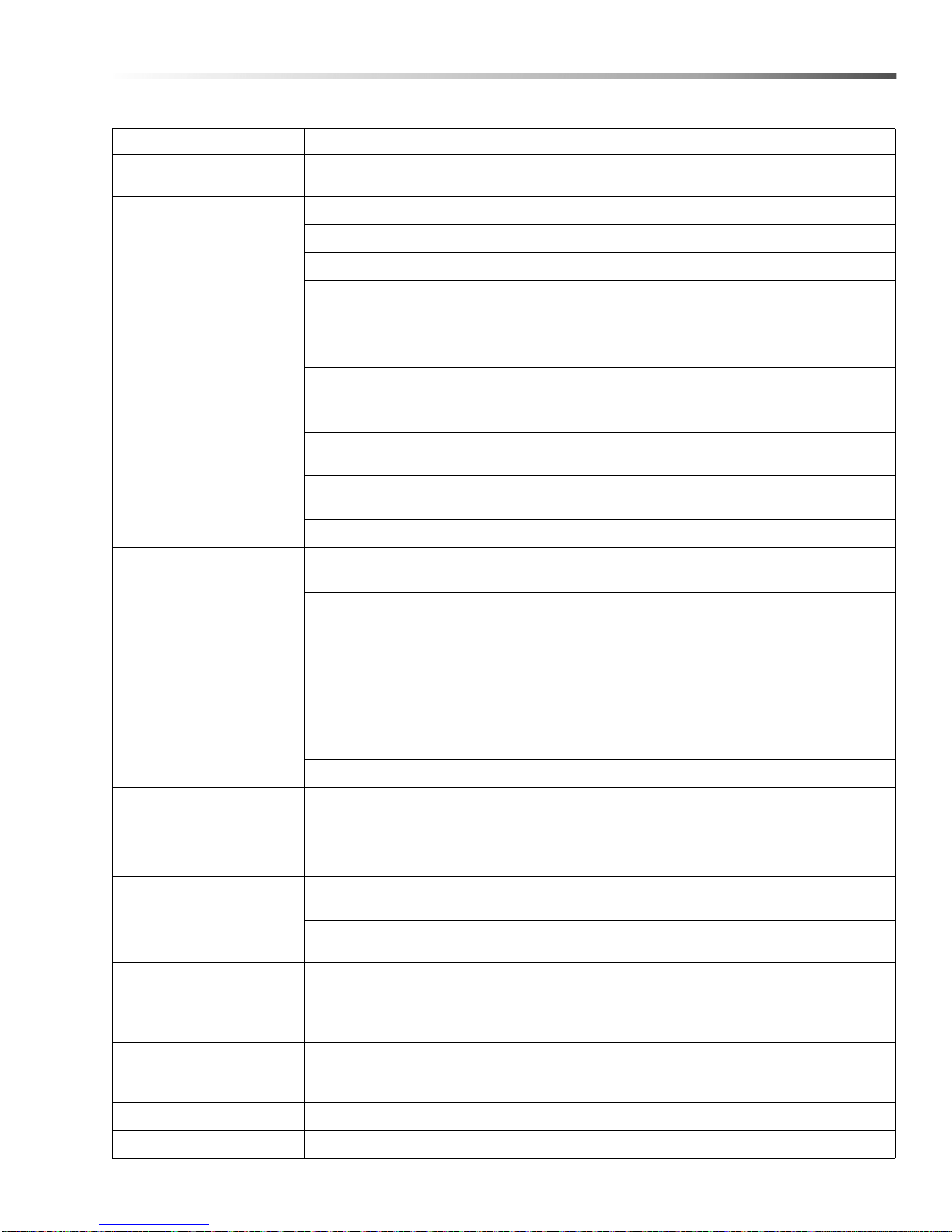
PROBLEM POSSIBLE CAUSE SOLUTION
PULSATION Faulty pulsation damper
LOW
PRESSURE
Maintenance
Check precharge. If low, recharge or install
new one.
Worn nozzle Replace with nozzle of proper size.
Belt slippage Tighten or replace with correct belt.
Air leak in inlet plumbing Disassemble, reseal and reassemble.
Relief valve stuck, partially plugged or
improperly adjusted. Valve seat worn
Inlet suction strainer clogged or
improperly sized
Worn packing.
Abrasives in pumped in cavitation. Inadequate water
Fouled or dirty inlet or discharge valves
Worn inlet, discharge valve blocked
or dirty
Clean and adjust relief valve; check for
worn or dirty valve seats. Kit available.
Clean. Use adequate size. Check more
frequently.
Install proper filter. Suction at inlet
manifold must be limited to lifting less than
20 feet of water or 8.5 psi vacuum.
Clean inlet and discharge valve
assemblies.
Replace worn valves, valve seats and/or
discharge hose.
PUMP RUNS
EXTREMELY ROUGH,
PRESSURE
VERY LOW
WATER LEAKAGE
FROM UNDER
MANIFOLD.
OIL LEAKING IN AREA
OF CRANKSHAFT
EXCESSIVE
PLAY IN END OF
CRANKSHAFT
PULLEY
WATER IN
CRANKCASE
OIL LEAKING FROM
UNDERSIDE OF
CRANKCASE
Leaky discharge hose Replace.
Restricted inlet or air entering the inlet
plumbing
Inlet restrictions and/or air leaks. Stuck
inlet or discharge valve
Worn packing Install new packing.
Worn crankshaft seal or improperly
installed oil seal O-ring
Bad bearing Replace bearing.
Worn main bearing from excessive
tension on drive belt
Humid air condensing into water inside
crankcase
Worn packing and/or piston rod sleeve;
O-rings on plunger retainer worn
Worn crankcase piston rod seals Replace seals.
Proper size inlet plumbing; check for air
tight seal.
Replace worn cup or cups. Clean out
foreign material. Replace worn valves.
Remove oil seal retainer and replace
damaged O-ring and/or seals.
Replace crankcase bearing and/or
tension drive belt.
Change oil intervals. Use any high grade
automotive 30 weight non-detergent oil.
Replace packing. Replace O-rings.
OIL LEAKING AT
REAR PORTION
OF CRANKCASE
LOUD KNOCKING Pulley loose on crankshaft Check key and tighten set screw.
NOISE IN PUMP Broken or worn bearing Replace bearing.
Landa VHP 2-1500 / 3-2000 Operator’s Manual 8.913-949 .0 - T
Worn crankcase piston rod seals Replace seals.
23
Page 24
Maintenance
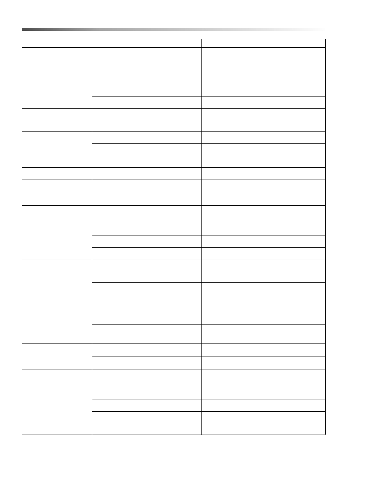
PROBLEM POSSIBLE CAUSE SOLUTION
Air in suction line
Check water supply and connections on
suction line.
PUMP
NOISY
PRESENCE OF
WATER IN OIL
WATER DRIPPING
FROM UNDER PUMP
OIL DRIPPING Oil seal worn Check and replace if necessary.
EXCESSIVE
VIBRATION IN
DELIVERY LINE
RELIEF VALVE
LEAKS WATER
BURNER WILL
NOT LIGHT
Broken or weak inlet or discharge valve
springs
Excessive matter in valves Check and clean if necessary.
Worn bearings Check and replace if necessary.
Oil seal worn Check and replace if necessary.
High humidity in air Check and change oil twice as often.
Piston packing worn Check and replace if necessary.
O-ring plunger retainer worn Check and replace if necessary.
Pump protector Check inlet water pressure.
Irregular functioning of the valves Check and replace if necessary.
Wrong nozzle size, debris in nozzle Clean or replace with correct nozzle.
No fuel Open gas valve.
Pilot light is out Light pilot.
Check and replace if necessary.
Defective high limit switch Replace switch.
BURNER SMOKES Stack restriction See venting under installation (page 7).
PILOT DOES
NOT LIGHT
PILOT IGNITES BUT
WILL NOT STAY ON
WHEN GAS COCK
DIAL IS RELEASED
SHORT
THERMOCOUPLE
LIFE
BURNER CYCLING ON/
OFF
WASHER WILL
NOT STEAM
Manual pilot valve closed Open pilot valve.
Gas leak in pilot Call qualified serviceman.
Piezo ignitor Adjust spark gap. Secure wires.
Pilot too far away from thermocouple Adjust thermocouple closer to flame.
Thermocouple loose at regulator safety
valve
Excessive heat from pilot light Decrease pilot supply gas.
Thermocouple too close to pilot Adjust thermocouple farther away.
Defective high limit switch Replace switch.
Steam valve closed Open valve (counterclockwise).
Burner not on Turn burner switch to "ON" position.
Coil dirty or sooty See coil maintenance section.
Tighten to firm fit.
Steam valve clogged Clean or replace.
24
Landa VHP 2-1500 / 3-2000 Operator’s Manual 8.913-949 .0 - T
Page 25

Parts
LANDA VHP
Parts
1.109-556.0
VHP2-1500
1.109-557.0
VHP3-2000
Landa VHP 2-1500 / 3-2000 Operator’s Manual 8.913-949 .0 - T
25
Page 26
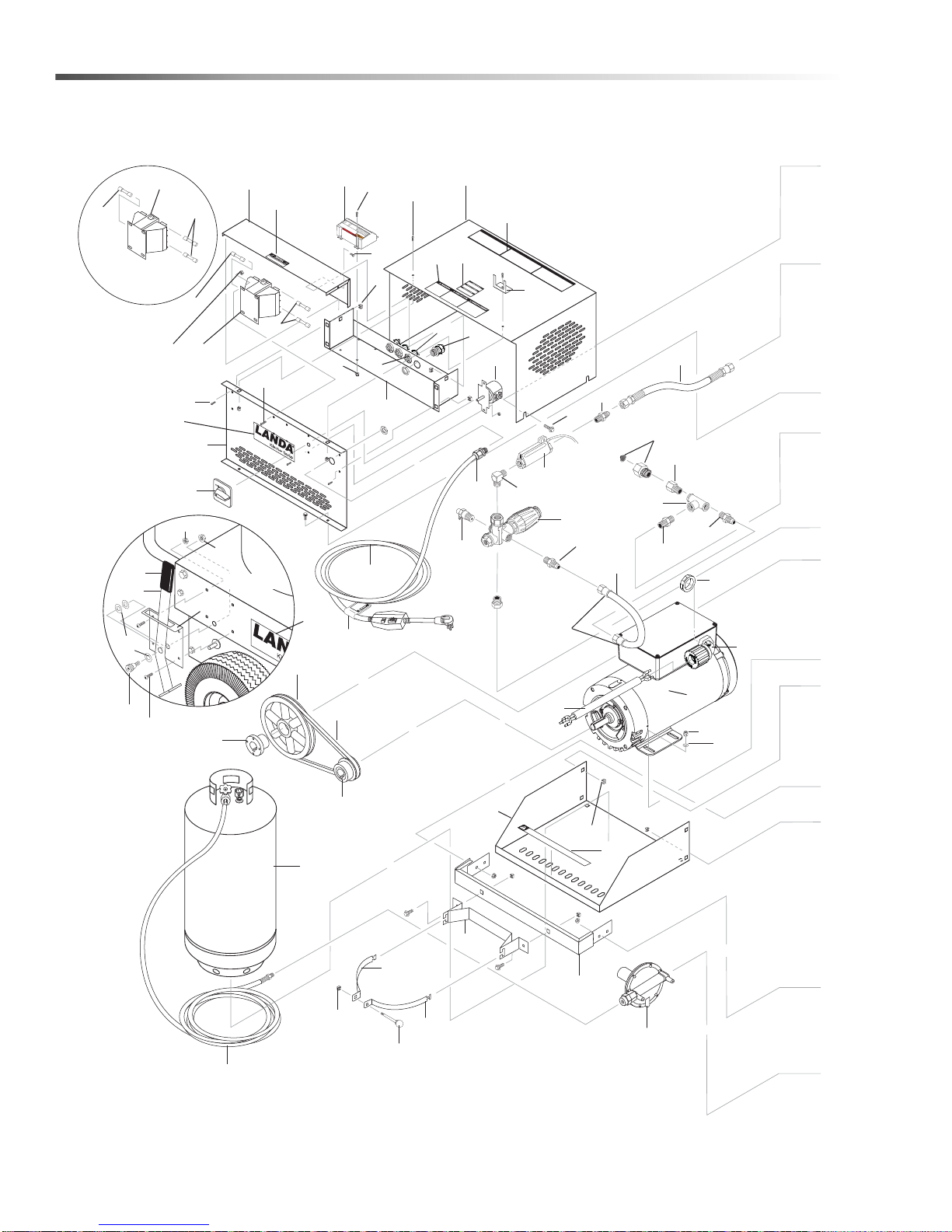
Landa VHP Left
53
54
46
47
55
36
3
2
37
15
15
129
21
125
45
43
42
31
28
38
1
Tank
(Not Included,
Optional)
44
14
13
27
35
34
30
25
29
19
16
109
110
114
115
116
52
7
39
8
137
9
12
10
4
6
140
32
24
41
50
48
43
112
108
84
20
49
51
26
13
131
16
111
143
144
40
133
33
18
146
145
View A-A
29
11
23
5
Electronic Ignition
(Optional)
17
127
OP
ERATING IN
ST
RU
CTIONS
INST
R
UC
CIONES DE OPERA
C
IO
N
INSTR
UCTI
ONS D' OPERATION
This machine
Do not conn
S
helf is
Re
mo
Read operator's manual b
f
ve
o
is designed to
ect to a p
r
v
trans
apo
r
p
p
o
r
r
rting
opane
opan
run
on
e b
tankfr
on pro
l
y
ottl
.
e
e
f
om shel
.
o
pane v
re star
f be
apor
ting.
f
o
fu
re ope
el.
ra
ting
T
h
i
.
Do
s
m
Shelf is
not
a
Rem
c
h
c
i
Read operator
ne
onn
o
f
ve
o
is
ect to a pr
r transpo
d
v
e
a
s
po
i
g
r p
n
e
ropan
d
r
's ma
opane
t
t
i
ng on
o
run
e tankfr
nual be
bottle
l
o
y
.
n
p
r
f
om
.
o
o
pane v
r
e star
she
lf bef
a
ting.
por
ore operating.
f
ue
l.
Thi
Do
s
m
S
not con
helf
a
Remo
chin
Read operator's m
i
s f
e is
ve v
n
or transpo
e
ct to a
d
e
apor pr
si
g
ne
pr
d
r
opane tan
o
ting on
to
pane bot
ru
a
n
n
u
on
l
al bef
y
.
k
t
p
l
f
e
ro
r
.
o
o
m
pane
re star
shelf before o
v
t
a
i
p
ng.
p
e
r
ating
.
or
fuel.
26
Landa VHP 2-1500 / 3-2000 Operator’s Manual 8.913-949 .0 - T
Page 27
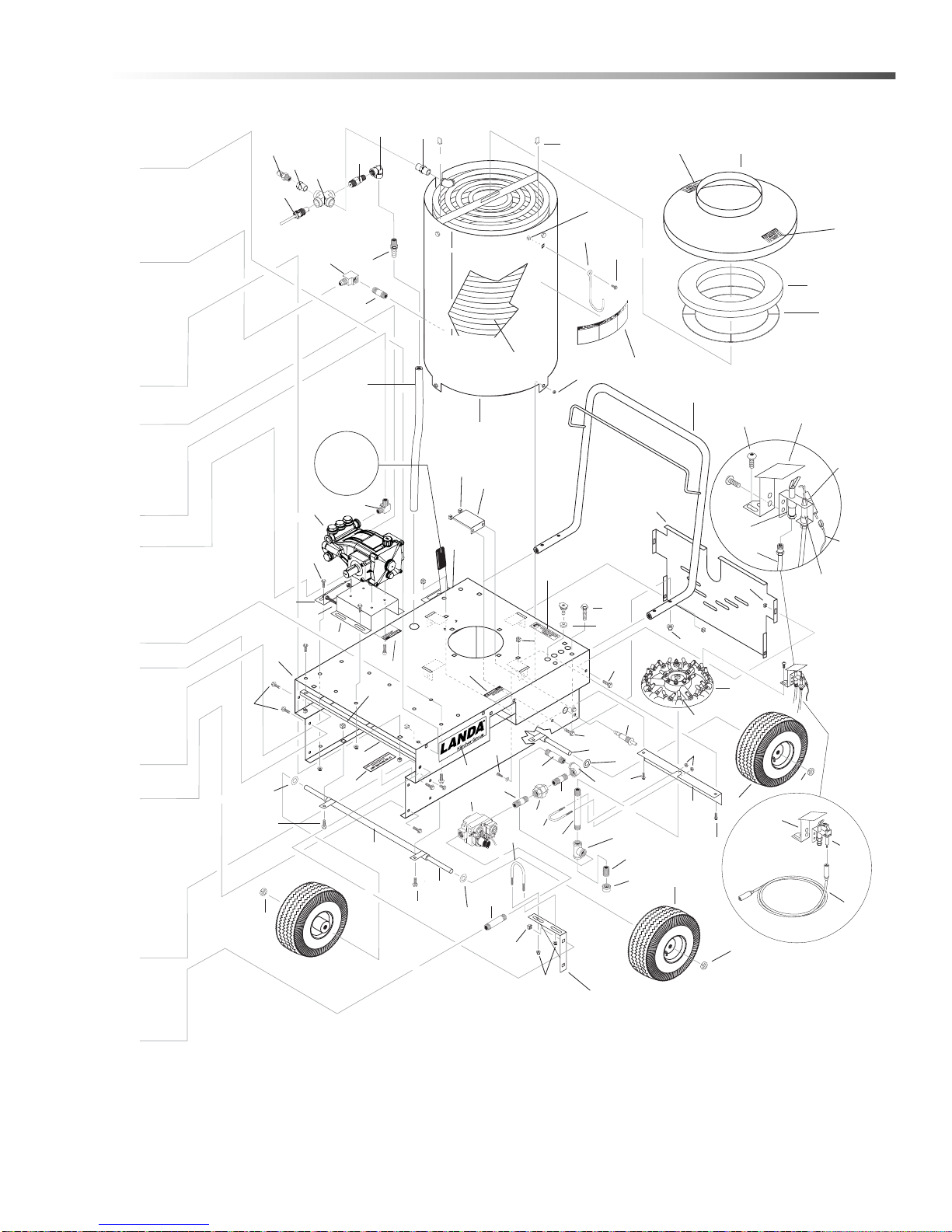
56
124
61
62
59
63
57
60
58
65
71
66
70
68
67
64
73
122
11
81
80
79
78
77
74
99
95
102
126
92
91
120
100
120
92
132
120
75
120
96
92
97
98
97
101
103
104
105
94
95
106
107
91
118
83
82
117
95
94
85
119
72
88
For
Detail See
View A-A
121
22
68
128
93
69
123
120
121
43
130
119
125
11
11
112
122
112
122
134
135
138
76
139
141
102
86
90
89
87
136
113
85
133
Electronic
Ignition Option
142
Landa VHP Right
.
O
.
C
.
E
27Landa VHP 2-1500 / 3-2000 Operator’s Manual 8.913-949 .0 - T
Page 28

Landa VHP
REF PART NO. QTY DESCRIPTION NOTES
1 8.912-918.0 1 COVER, ELECTRICAL BOX
2 9.800-016.0 1 LABEL, DISCONNECT PWR SUPPLY
3 9.802-764.0 2 SCREW, 10/32" X 3/4", HEX
4 9.802-551.0 1 TRANSFORMER 240/480V - 120V (3-2000)
5 8.716-173.0 1 FUSE, PAPER 1 AMP 250V MIDGET (3-2000)
6 8.933-007.0 2 FUSE, 1 AMP 600V MIDGET (3-2000)
7 9.802-793.0 7 NUT, CAGE, 1/4" X 16 GA.
8 8.912-917.0 1 BOX, ELE CTRICA L, VHW, BELT
- 9.802-762.0 1 SCREW, 10/32" X 1-1/4" NOT SHOWN
- 9.802-695.0 6 NUT, 10/32" KEPS NOT SHOWN
- - 10 NUT, 10/32" KEPS (ELECTRIC IGNITION)
- 9.800-040.0 1 LABEL, GROUND NOT SHOWN
9 8.912-919.0 1 COVER, PUMP & MOTOR, VHW BELT
10 8.912-888.0 1 HOLDER, WAND BRACKET, VHW/VHP
11 9.802-754.0 16 SCREW, 1/4" X 1/2", HH NC, WHIZ LOC
12 9.800-033.0 1 LABEL, WARNING HOT WATER
13 9.802-449.0 1 SWITCH, 3 PS, 115V -230 V, 1 PH
14 8.912-916.0 1 PANEL, CONTROL, VHW, BELT
15 9.802-759.0 8 SCREW, 10/32" X 1/2" BHSOC BLK
- - 12 SCREW, 10/32" X 1/2" BHSOC BLK (ELECTRIC IGNITION)
16 9.802-776.0 5 NUT, 5/16", ESNA, NC
17 9.802-553.0 1 TRANSFORMER, 120/240 -24V .050 KVA
18 9.802-514.0 3 STRAIN RELIEF, 1/2" LQ TITE
19 9.802-525.0 3 LOCKNUT , 1/ 2"
20 9.802-433.0 1 PLUG, GFCI, 240V, 20 AMP (3-2000)
- 9.802-431.0 1 CORD W/GFCI, 120V 20 AMPS (2-1500)
21 8.932-969.0 1 LABEL, WARNING, SERVICE CORD
22 9.802-772.0 2 SCREW, 10/32" X 1/4"
23 9.802-771.0 4 SCREW, 10/32" X 3/4"
24 9.802-146.0 1 SWIVEL, 1/2" MP X 3/4" GHF W/STRAINER
25 8.933-006.0 1 SWITCH FLOW MV 60, YELLOW
26 8.918-210.0 1 HOSE, 3/8" X 16", 2 WIRE, PRESSURE LOOP
27 8.750-299.0 1 UNLOADER, VRT 3, 8 GPM @4500 PSI
28 8.706-168.0 1 ELBOW, 3/8" MALE PIPE
29 9.802-695.0 8 NUT, 10/32” KEPS
30 9.802-127.0 1 NIPPLE, 1/2" JIC X 3/8" PIPE
31 9.802-036.0 1 NIPPLE, 1/2" JIC X 3/8" PIPE
32 9.802-767.0 4 SCREW, 3/8" X 3/4" WHIZ LOC
33 8.900-822.0 1 LABEL, VHP OPERATING INSTR.
34 8.706-984.0 1 ADAPTER, 1/2" X 1/2" PIPE
35 8.706-844.0 1 TEE 1/2" FEMALE, PIPE
36 8.706-797.0 1 NIPPLE, 1/2" HEX
(ELECTRONIC
IGNITION OPTION)
28
Landa VHP 2-1500 / 3-2000 Operator’s Manual 8.913-949 .0 - T
Page 29

Landa VHP
REF PART NO. QTY DESCRIPTION NOTES
37 9.802-128.0 1 NIPPLE, 1/2" JIC X 1/2" PIPE
38 8.707- 25 4 .0 1 PUMP PROTECTOR, 3/8" PTP
39 9.802-151.0 2 SWIVEL, 1/2" JIC FEM, PUSH-ON
40 9.802-259.0 12" HOSE, 1/2" PUSH-ON
41 8.754-710.0 1 MOTOR, 2 HP, 1 PH 3470 RPM, C-FACE (2-1500)
- 9.802-341.0 1 MOTOR, 5 HP 1 PH 3450 RPM C-FACE (3-2000)
- 9.800-032.0 1 LABEL, MOTOR OVERLOAD RESET, LEXAN NOT SHOWN
42 8.912-873.0 1 SUPPORT, PROPANE TANK, VHP
43 9.802-792.0 16 NUT, CAGE, 3/8" X 12 GA.
44 8.912-864.0 1 BRACE, LP BOTTLE, VHP
45 8.912-879.0 1 BRACKET, PROPANE TANK, VHP
46 8.912-882.0 1 STRAP, PROPANE TANK, R/H VHP
47 8.912-885.0 1 STRAP, PROPANE TANK, L/H VHP
48 8.719-063.0 1 KNOB, 3/8" - 16 X 1-1/2" VHP
49 9.804-029.0 1 PULLEY, AK64H (2-15024D)
- 9.802-380.0 1 PULLEY, BK80H (3-20024A)
50 8.715-517.0 1 PULLEY, BORE, AK21 X 5/8" (2-15024D)
- 9.802-377.0 1 PULLEY, BK32 (3-20024A)
- 9.803-897.0 1 BUSHING, H X 3/4
51 9.802-402.0 1 BUSHING, HX24MM
52 9.804-026.0 1 BELT, AX31 (2-15024D)
- 9.802-413.0 1 BELT, BX32 (3-20024A)
53 8.717-749.0 1 REGULATOR, PROPANE, R532CFF
54 8.711-851.0 1 HOSE, 3/8" X 10', PROPANE ASSEMBLY
55 8.717- 79 0 .0 1 TANK, PROPANE 10.5 GAL. 30 LB. W/ GAUGE OPTIONAL
56 8.712- 18 5 .0 1 SWITCH, SNAP, 225 DR HI-LIMIT
57 8.706- 85 1 .0 1 CROSS, 1/2' FORGED, GALV. 3000WP
58 9.802-171.0 1 NIPPLE, 3/8" X 3/8" NPT ST MALE
59 9.802-013.0 1 NIPPLE, 1/2" X 2.5" GALV.
60 8.707-381.0 1 RUPTURE DISC ASSY, 8500#
61 8.706-167.0 1 ELBOW, 3/8" FPT, 90 DGR
62 9.802-259.0 30" HOSE, 1/2", PUSH-ON
63 9.802-043.0 1 ELBOW, 1/2" JIC X 1/2" FEM, 90 DGR
64 8.915-981.0 1 WRAP, OUTER COIL, VHW
- 9.800-021.0 1 LABEL, HOT WATER OUTLET NOT SHOWN
65 9.803- 13 4 .0 1 COIL, DURA, 14.5" DIA, SCH 80
66 8.71 9-96 8 .0 1 HOLDER, WAND, VHW/VHP ZINC PLATED
67 9.803-029.0 1 TANK HEAD ASSEMBLY, 16" DIA X 8" STACK
68 9.800-006.0 2 LABEL, "HOT/CALIENTE" W/ARROWS
69 9.802-825.0 4 RETAINER CLIP
70 9.802-904.0 1 INSULATION, TANK HEAD 16" OD X 8" ID
71 8.912-899.0 1 HANDLE, VHW/VHP/MVP W/HNG
NOT SHOWN
(3-20024A)
29Landa VHP 2-1500 / 3-2000 Operator’s Manual 8.913-949 .0 - T
Page 30

Landa VHP
REF PART NO. QTY DESCRIPTION NOTES
72 8.912-871.0 1 PANEL, CHASSIS, FRONT/BACK
73 8.912-881.0 1 REFLECTOR, PILOT LIGHT, VHP/VHG
74 9.802-678.0 1 IGNITOR, PIEZO
75 8.912-875.0 1 SUPPORT, BURNER RING
76 9.802-778.0 4 NUT, WHIZ LOC 5/16 FLANGE
77 8.923-753.0 1 PUMP, LANDA LB3030R, 3.0@3000, 1650 RPM
78 8.912-920.0 1 RETAINER, TAKE-UP, PUMP
79 9.802-733.0 2 BOLT, 3/8" X 3-1/2" TAP
80 9.803-131.0 1 RAIL, PUMP COMBO
81 8.912-923.0 1 BASE, MAIN, VHP, BELT
82 8.718-054.0 1 BURNER RING, X-11 W/640-69 JET ORIFICES
83 9.802-064.0 1 GROMMET, RUBBER, NOZZLE HOLDER
84 9.802-463.0 1 FUSE, PAPER, BUSS FNM-1/2 250V MIDGET TD
85 8.912-890.0 1 BRACKET, PILOT LIGHT, VHP/VHG
- 8.719-957.0 1
86 8.718-150.0 1 PILOT, VHP
- 8.718-075.0 1 ORIFICE, PILOT, LP, SMALL NOT SHOWN
87 8.718-092.0 1 THERMOCOUPLE, 24" WHITE RODGERS
88 9.802-681.0 1 WIRE, 15" ASSEMBLY
- 9.802-682.0 1 TCB, GND NOT SHOWN
89 8.718-069.0 1 ELECTRODE, PIEZO ASSEMBLY
90 9.802-911.0 36" TUBING, ALUMINUM, 1/4" DEADSOFT
91 8.912-868.0 2 AXLE, 23", VHW
92 9.802-810.0 4 WASHER, 5/8", FLAT, SAE
93 9.800-031.0 1 LABEL, VHP PILOT LIGHT
94 8.754-186.0 4 QH WHEEL ASSY, 10" GRAY STEEL W/TUB
95 9.802-782.0 4 COLLAR, 5/8" BORE SHAFT
96 9.802-027.0 1 ELBOW, 3/4", BLACK, 90°
97 9.802-018.0 2 NIPPLE, 3/4" X 3". BLACK PIPE
98 9.802-049.0 1 UNION, 3/4", BLACK PIPE
99 8.718-045.0 1 VALVE, GAS, WR 36103A-410, 3/4"
- 9.803-616.0 1 VALVE, GAS
- 9.803-618.0 1 LP,CONVERT KIT,ELEC IGN NOT SHOWN
100 8.912-858.0 2 AXLE, HOLDER ASSEMBLY VHW/VHP
101 8.706-108.0 1 NIPPLE, BLK, PIPE 3/4" X 3-1/2"
102 8.718-648.0 2 U-BOLT, 1/4" X 1-1/2" X 2-1/2" W/PLATE
103 8.706-108.0 1 NIPPLE, 3/4" X 3-1/2", BLACK PIPE
104 8.706-222.0 1 TEE, 3/4" NLK PIPE
105 9.802-018.0 1 NIPPLE, 3/4" X 3", BLACK PIPE
106 8.706-320.0 1 CAP, 3/4", BLACK PIPE
BRACKET, PILOT LIGHT, VNG-S(ELECTRIC
IGNITION)
(ELECTRONIC
IGNITION OPTION)
(ELEC. IGN.)
NOT SHOWN
30
Landa VHP 2-1500 / 3-2000 Operator’s Manual 8.913-949 .0 - T
Page 31

Landa VHP
REF PART NO. QTY DESCRIPTION NOTES
107 8.912-877.0 1 SUPPORT, GAS TRAIN, VHP/VHG
108 9.804-608.0 1 CAP, VINYL FKT (YELLOW)
109 8.912-930.0 1 ASSY, LEVER BRAKE
110 8.912-928.0 1 BRACKET, WHEEL BRAKE
111 8.718-980.0 12 WASHER, 5/16", FLAT, SAE
112 9.802-775.0 8 NUT, 1/4" FLANGE, WHIZ LOC
113 9.803-610.0 1 PILOT, IGNITOR (ELECTRIC IGNITION)
114 9.802-807.0 8 WASHER, 3/8", SAE, FLAT
115 8.718-785.0 1 SCREW, 3/8" X 3/8", SCKT
116 9.802-765.0 4 SCREW, 1/4" X 1/2" BH SOL CS
117 9.802-684.0 32 JET ORIFICE #69, DRILL TO #66
118 9.802-769.0 4 SCREW, 3/8" X 1-3/4" WHIZ LOC
119 9.802-781.0 11 NUT, 3/8" FLANGE WHIZ LOC
120 9.802-767.0 18 SCREW, 3/8" X 3/4" WHIZ LOC
121 8.932-965.0 2 LABEL, EXPOSED PULLEY
122 9.802-794.0 10 NUT, CAGE, 1/4" X 12 GA
123 8.706-168.0 1 ELBOW, 3/8" MALE PIPE
124 8.705-975.0 1 NIPPLE, 1/2" HEX STEEL
125 8.916-090.0 2 LABEL, LANDA
126 8.706-109.0 1 NIPPLE, 3/8" X 7", BLACK PIPE
127 8.933-007.0 2 FUSE, KTK-R1 600V MIDGET FUSE
128 9.802-753.0 5 SCREW, 1/4" X 3/4", WHIZ LOC
129 8.900-300.0 1 LABEL, LANDA
130 8.932-963.0 1 LABEL, LIQUID PROPANE
131 8.900-829.0 1 LABEL, VHP, PROPANE TANK
132 8.912-894.0 1 BRACE, CHASSIS
133 9.803-562.0 1 CABLE, IGNITION, 48” (ELECTRIC IGNITION)
134 8.707-019.0 1 HOSE BARB, 1/2" BARB X 3/8" MPT, PUSH-ON
135 9.800-018.0 1 LABEL, TIPOVER HAZARD
136 9.800-049.0 1 LABEL, MANUFACTURER'S CLEANING SOLUTIONS
137 9.803-613.0 1 MODULE, IGNITION, ELECTRONIC
138 9.803-108.0 1 RETAINER RING, INSULATION
139 8.718-618.0 4 BOLT, 5/16" X 3/4" NC
140 9.802-518.0 1 STRAIN RELIEF 3/4
141 9.802-793.0 5 NUT, CAGE, 1/4" X 16 GA
142 8.706-294.0 1 BUSHING, 1/2 X 3/8 STEEL
143 8.755-957.0 1 STRAIN RELIEF, 3/4", 90DEG, BLK
144 9.802-427.0 2.75 FT CORD, SERV, 12/3, SEOOW, /FT
145 9.802-523.0 1 LOCKNUT, 3/4" CONDUIT
146 9.802-518.0 1 STRAIN RELIEF, STR, 3/4
(ELECTRONIC
IGNITION OPTION)
31Landa VHP 2-1500 / 3-2000 Operator’s Manual 8.913-949 .0 - T
Page 32
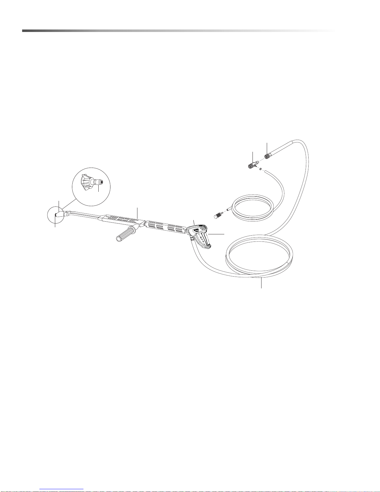
Hose & Spray Gun
2
3
High Pressure
Nozzle
6
7
8
5
1
4
3
32
Landa VHP 2-1500 / 3-2000 Operator’s Manual 8.913-949 .0 - T
Page 33
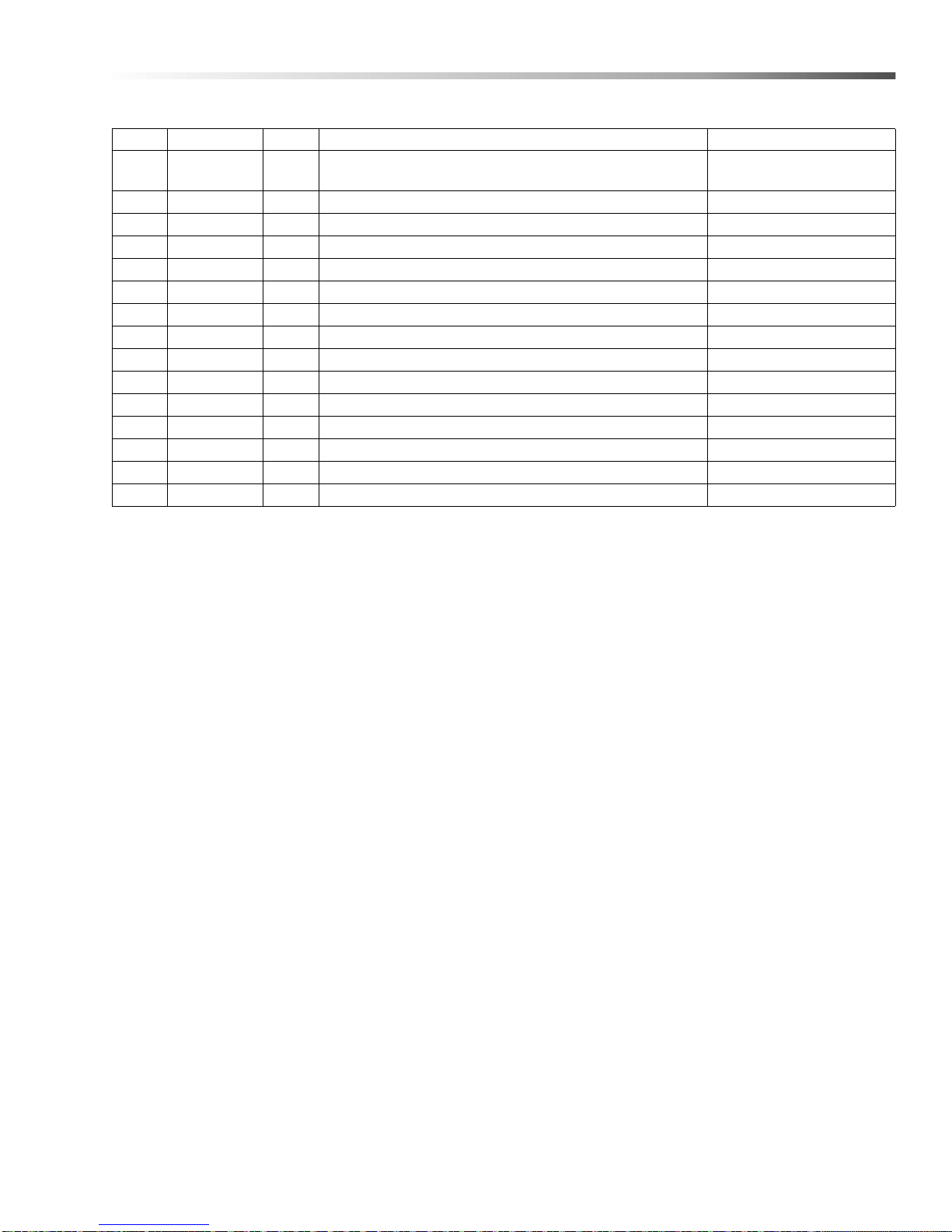
Hose & Spray Gun
REF PART NO. QTY DESCRIPTION NOTES
1 9.802-224.0 1
2 9.802-166.0 1 COUPLER, 3/8" FEMALE
- 9.802-100.0 1 QUICK COUPLER O-RING, 3/8"
3 8.739-026.0 1 HOSE, 3/8" X 50', 1-WIRE, TUFF-SKIN
4 4.775-054.0 1 EASY! FORCE ADVANCED KNA
5 8.711-293.0 1 WAND, ONLY, VP, ZINC
6 9.802-286.0 1 BRASS SOAP NOZZLE, 1/8"
7 9.802-165.0 1 COUPLER, 1/4" MALE, BRASS
- 9.802-096.0 1 QUICK COUPLER O-RING, 1/4"
8 8.712-333.0 1 NOZZLE, SAQCMEG 1503, YELLOW (2-1500)
- 8.712-338.0 1 NOZZLE, SAQCMEG, 15035,YELLOW (3-2000)
- 8.712-346.0 1 NOZZLE, SAQCMEG 1504, YELLOW (2-1100)
- 8.712-358.0 1 NOZZLE, SAQCMEG 1505.5 YELLOW (3-700)
9 8.707-139.0 1 COUPLER, 1/4"PLUG, MALE, STEEL/ZINC NOT SHOWN
10 9.802-164.0 1 COUPLER, 1/4"SOCKET, FEMALE, BRASS NOT SHOWN
DOWNSTREAM INJECTOR ASSY.,
NON ADJ #2, 2-3 GPM
33Landa VHP 2-1500 / 3-2000 Operator’s Manual 8.913-949 .0 - T
Page 34
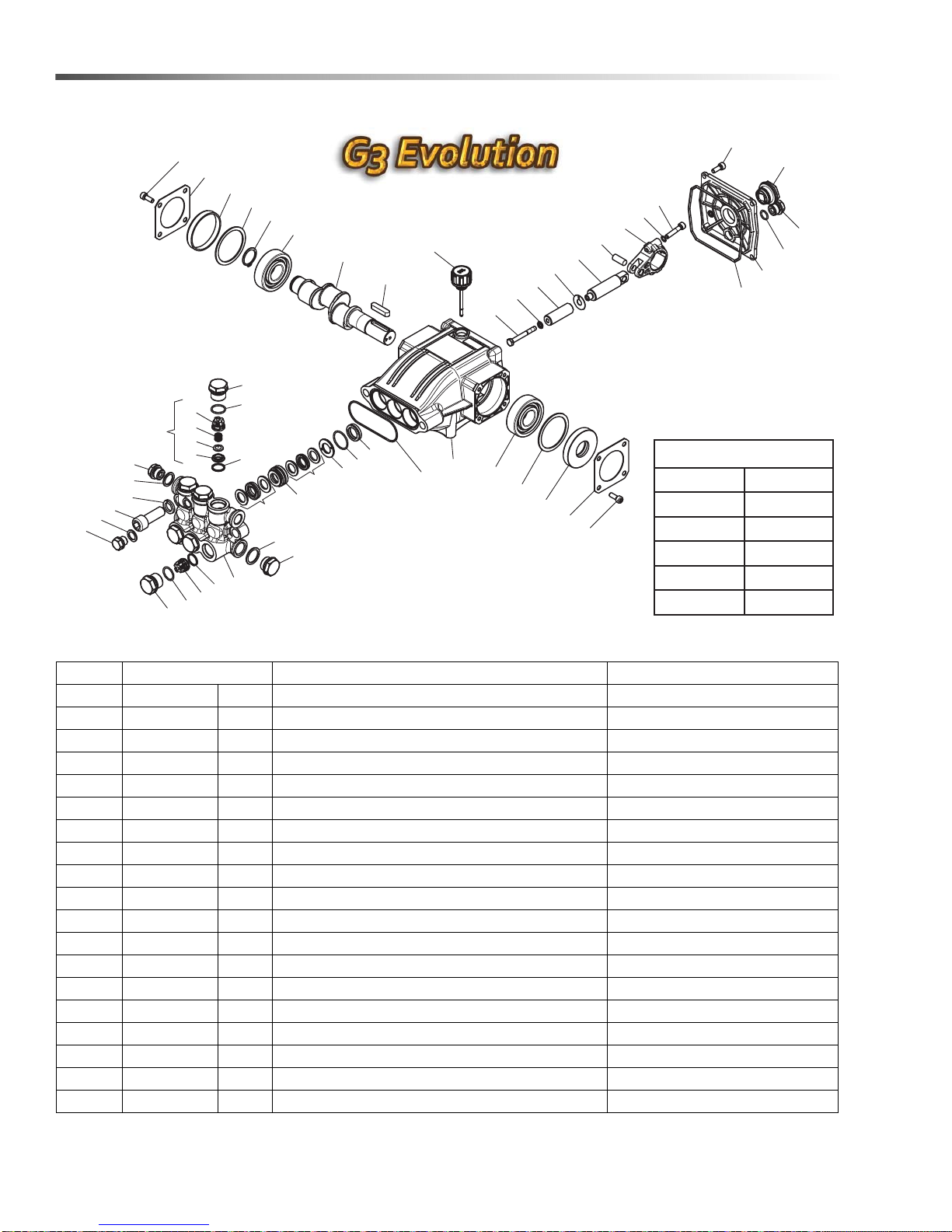
LB Series Pump
13
6
8
1
2
3
9
10
11
12
13
14
15
21
20
18
17
16
12
14
15
22
23
24
25
26
27
28
29
30
31
32
33
34
31
29
35
27
26
36
37
38
39
40
42
41
43
44
45
46
26
47
22
19
5
7
4
48
TORQUE SPECS
ITEM # FT. LBS.
15 65
18 66
26 8
36 10
44 10
REF PART NO. QTY DESCRIPTION NOTES
1 8.754-841.0 1 CRANKCASE
2 8.754-846.0 1 O-RING Ø1.78 X 72.75
3 - 3 PLUNGER OIL SEAL SEE TABLE KITS
4 - 3 O-RING Ø1.78 X 26.7 SEE TABLE KITS
5 - 3 WASHER, PRESSURE RING 16 MM SEE TABLE KITS
6 - 3 U-SEAL, 16 MM SEE TABLE KITS
7 - 3 PRESSURE RING, 16 MM SEE TABLE KITS
8 9.803-199.0 3 U-SEAL, 16 MM SEE TABLE KITS
9 9.803-199.0 1 WASHER, COPPER G1/2
10 9.802-926.0 1 PLUG, BRASS G1/2
11 8.754-852.0 1 MANIFOLD
12 8.717-233.0 6 O-RING Ø1.78 X 15.6 SEE TABLE KITS
13 - 6 VALVE ASSEMBLY SEE TABLE KITS
Landa VHP 2-1500 / 3-2000 Operator’s Manual 8.913-949 .0 - T
14 9.803-948.0 6 O-RING Ø1.78 X 18.77 SEE TABLE KITS
15 9.803-949.0 6 VALVE PLUG
16 8.754-851.0 1 PLUG, BRASS G1/4
17 8.718-973.0 1 WASHER, COPPER G1/4
18 8.754-854.0 2 BOLT, MANIFOLD M14 X 40
19 8.754-850.0 2 WASHER, LOCK
34
Page 35
LB Series Pump
REF PART NO. QTY DESCRIPTION NOTES
20 9.803-198.0 1 WASHER, COPPER G3/8
21 8.707-262.0 2 PLUG, BRASS G3/8
22 - 6 VALVE SEAT SEE TABLE KITS
23 - 6 VALVE PLATE SEE TABLE KITS
24 - 6 VALVE SPRING SEE TABLE KITS
25 - 6 VALVE CAGE SEE TABLE KITS
26 9.802-939.0 12 SCREW, M6 X 16
27 8.717-137.0 2 BEARING COVER
28 9.803-954.0 1 BEARING SEAL
29 8.754-843.0 2 SEAL SPACER, CRANKSHAFT
30 9.802-914.0 1 SNAP RING, 25 MM
31 9.803-955.0 2 BEARING, BALL
32 8.754-829.0 1 SHAFT, 24 MM 3030
- 8.754-830.0 1 SHAFT, 24 MM 4025
33 9.803-167.0 1 KEY, CRANKSHAFT
34 8.754-219.0 1 OIL DIPSTICK
35 8.933-010.0 1 SEAL, CRANKSHAFT
36 8.754-855.0 3 BOLT, PLUNGER SEE TABLE KITS
37 8.754-092.0 3 SPACER, COPPER SEE TABLE KITS
38 8.754-848.0 3 PLUNGER, 16 MM SEE TABLE KITS
39 9.803-962.0 3 SPACER, COPPER SEE TABLE KITS
40 8.754-827.0 3 PLUNGER ROD
41 9.803-965.0 3 CONNECTING ROD PIN
42 9.803-966.0 3 CONNECTING ROD
43 9.803-218.0 6 WASHER, 6 MM
44 8.933-020.0 6 SCREW, CONNECTING ROD
45 8.754-847.0 1 O-RING Ø2.62 X 111.62
46 8.754-842.0 1 COVER, CRANKCASE
47 9.803-906.0 1 O-RING Ø1.78 X 14
48 9.803-202.0 1 SIGHT GLASS, G3/4
KIT NUMBERS 8.754-856.0 8.754-857.0 8.754-858.0 8.754-859.0 9.803-937.0
KIT DESCRIPTION
ITEM NUMBERS
INCLUDED
NUMBER OF
CYLINDERS KIT
WILL SERVICE
Plunger Seals
16 mm
4, 6, 8 4, 5, 6, 7, 8 36, 37, 38, 39 12, 13, 14 3
Seal Packing
16 mm
31163
Plunger
16 mm
Complete
Valve
Plunger Oil
Seals
35Landa VHP 2-1500 / 3-2000 Operator’s Manual 8.913-949 .0 - T
Page 36
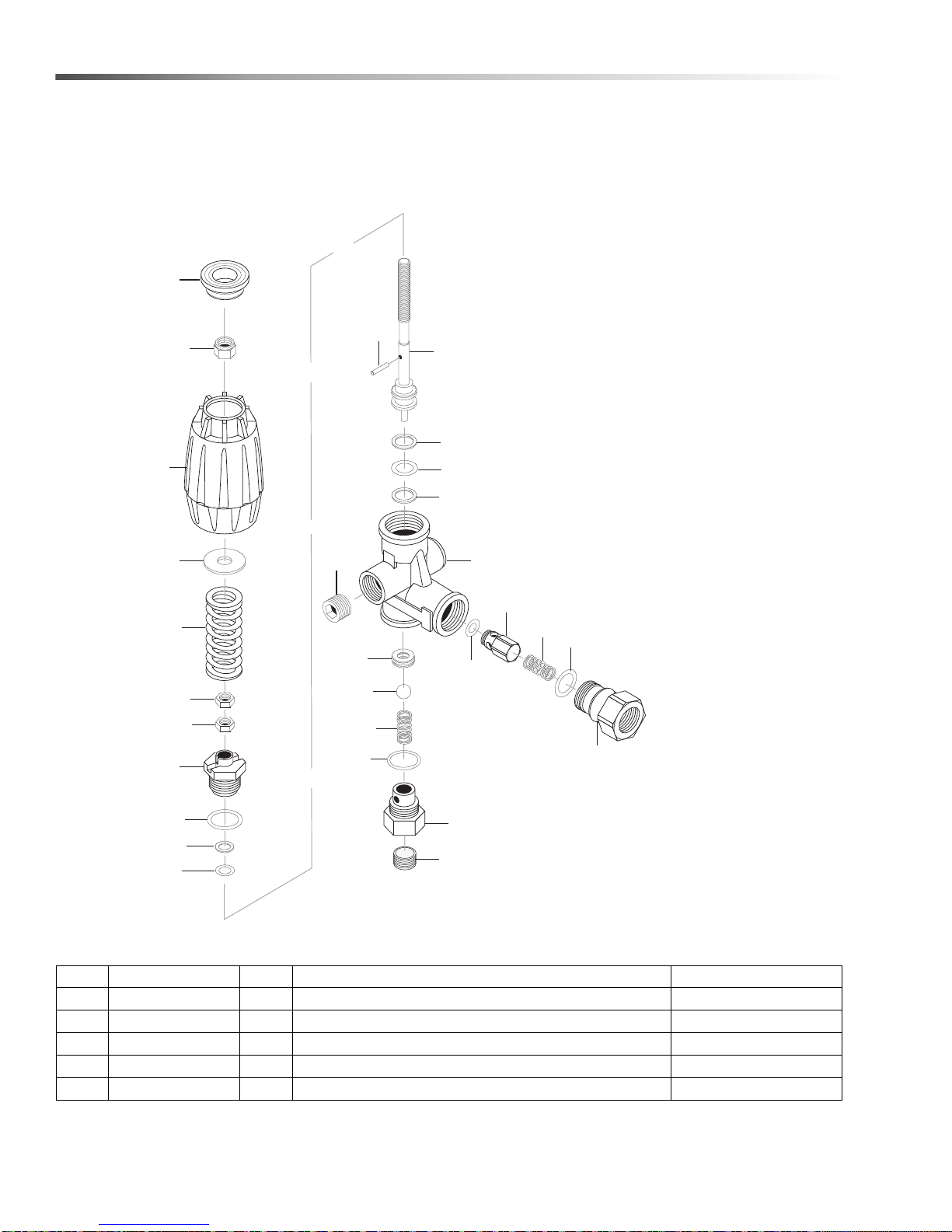
VRT3 Unloader
8.750-297.0, 8 GPM, 2320 PSI
8.750-298.0, 8 GPM, 3630 PSI
8.750-299.0, 8 GPM, 4500 PSI
9
8
23
26
2
3
16
1
10
24
11
6
4
13
14
20
25
12
22
19
15
15
21
17
18
7
9
5
6
REF PAR T NO. QTY DESCRIPTION NOTES
25 8.750-713.0 1 OUTLET FITTING
18 8.750-712.0 1 KNOB, UNLOADER
- 8.750-709.0 - REPAIR KIT, VRT3, 2320/3630 PSI
- 8.750-710.0 - REPAIR KIT, VRT3, 4500 PSI
- - - (KIT ITEMS: 3, 4, 6, 9-12, 21, 24)
36
Landa VHP 2-1500 / 3-2000 Operator’s Manual 8.913-949 .0 - T
Page 37

VRT3 Unloader
Unloader Adjustment Procedures
1. Remove lock nut (Item 19).
2. Remove adjustment knob (Item 18).
3. Loosen the two (2) nuts (Item 15), move them upward on stem (Item 8) until you see 4 or more threads below
the nut.
4. Re-attach adjusting knob (Item 18).
5. Start machine. Open the trigger of the spray gun. Increase pressure by turning adjustment knob (Item 18)
clockwise until pressure is at the desired operating pressure.
6. Remove the adjustment knob (Item 18), tighten the lower nut (Item 15) tightly against the upper nut (Item 15).
Re-attach adjustment knob (Item 18) and screw down until contact is made with the nuts (Items 15). Screw
down lock nut (Item 19) onto the stem (Item 8) until the threads cut into the nylon insert of the lock nut
(Item19).
*If adjustment knob (Item 18) DOES NOT make contact with upper nut (Items 15), remove adjusting knob (Item
18), re-adjust (raise) nuts (Items 15) on stem (Item 8) and re-attach adjustment knob (Item 18), then repeat
step #6.
**If adjustment knob (Item 18) DOES make contact with upper nut; release the trigger of the spray gun and
watch the pressure gauge for the pressure increase (“spike”). This “spike” SHOULD NOT exceed 500 psi
above the operating pressure. If “spike” pressure exceeds the 500 psi limit, remove the adjusting knob (Item
18) and re-adjust (lower) the nuts (Items 15) on the stem (Item 8). Re-attach the adjusting knob (Ite m 18), then
repeat step #6.
37Landa VHP 2-1500 / 3-2000 Operator’s Manual 8.913-949 .0 - T
Page 38
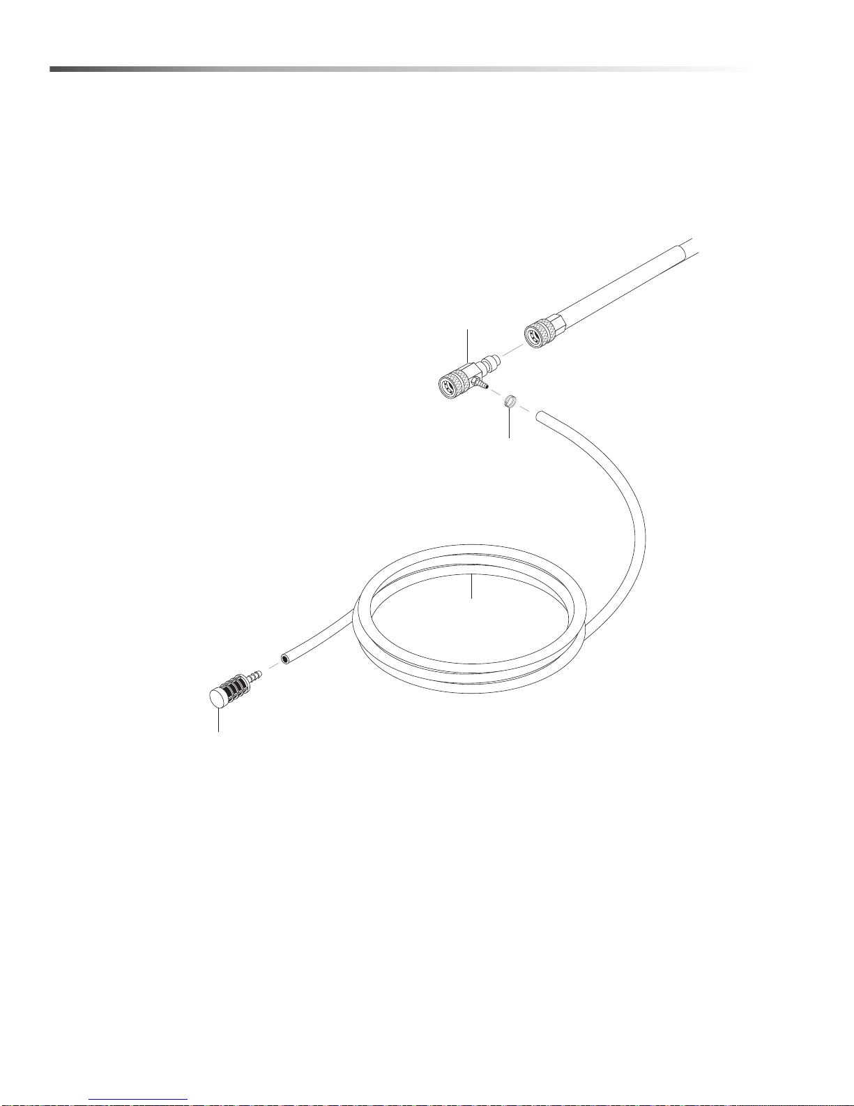
Injector Assembly #2 - 4 - 011182
1
2
3
4
3-1100, 3-2000
38
Landa VHP 2-1500 / 3-2000 Operator’s Manual 8.913-949 .0 - T
Page 39

Injector Assembly #2 - 4 - 011182
REF PART NO. QTY DESCRIPTION NOTES
1 9.802-215.0 1
2 6.390-126.0 1 CLAMP, HOSE, .46-, .54 ST
3 9.802-251.0 6 ft. TUBE, 1/4" X 1/2", CLEAR VINYL
4 8.707-057.0 1 STRAINER, 1/4", HOSE BARB
INJECTOR, DETERGENT, NON ADJUST,
#2, 2-3 GPM
39Landa VHP 2-1500 / 3-2000 Operator’s Manual 8.913-949 .0 - T
Page 40
Spanish
ADVERTENCIA
OPERATIONS
SAFETY
MAINTENANCE
ADVERTENCIA
ADVERTENCIA
ADVERTENCIA
Gracías por comprar un Lavadora a Presión Landa.
Estas instrucciones y advertencias corresponden a los
modelos VHP.
Landa se reserva el derecho de hacer cualquier
cambio en cualquier momento sin contraer ninguna
obligación.
Responsabilidades del Dueño/Usuario:
El dueño y/o usuario debe estar al tanto de las instrucciones de operación y de las advertencias del fabricante antes de usar su lavadora a presión Landa. La
información de advertencia debe ser enfatizada y
comprendida. Si el operador no domina el inglés, el
comprador/dueño deberá leer y discutir con éste las
instrucciones y las advertencias del fabricante en el
idioma natal del operador, asegurándose de que éste
entienda su contenido.
El dueño y/o usuario debe estudiar y mantener las
instrucciones del fabricante para futuras referencias.
CUIDAR ESTAS INSTRUCCIONES
Este manual debe ser considerado una parte
permanente de la máquina y debe quedarse
consigo si máquina es revendida. Al ordenar las
partes, especifican por modelo y número de serie.
Utilice repuestos sólo idénticos. Esta máquina
debe ser utilizada solamente por los operadores
entrenados.
Seguridad De La Maquina
PRECAUCION: Para reducir el
riesgo de accidentes, lea las
instrucciones cuidadosamente
antes de usar la unidad.
1. Lea todo el manual para operadores cuidadosamente. Al no
seguir las instrucciones puede
causar el mal funcionamiento de
la unidad y provocar la muerte, o
causar serias heridas y/o daños
en la propiedad.
2. Todas las instalaciones deben cumplir con los
códigos locales. Póngase en contacto con un
técnico eléctrico, plomero, compañía de servicios
públicos o distribuidor de ventas para mayores
detalles.
ADVERTENCIA: Riesgo de
asfixia. Use este producto solo en
areas bien ventiladas.
3. Evite instalar unidades en áreas
pequeñas o cerca de ventiladores de gases de escape. Los
gases de escape contienen gas
venenoso de monóxido decarbono; la exposición puede
causar pérdida del conocimiento
y causar la muerte. Los gases de escape también
contienen químicos, en ciertas cantidades, que se
sabe, causan cáncer, defectos de nacimiento, o
daños al sistema reproductivo.
ADVERTENCIA: Liquidos inflamables pueden crear gases que se
encienden causando daños a la
propiedad y heridas severas.
4. Aparatos de encendido con
petróleo deberán de ser instalados en lugares donde residuos
de combustibles, vapores o
gases inflamables no estén
normalmente presentes.En modelos de encendido
con petróleo utilice únicamente kerosene #1 o
diesel. No utilize gasolina, solventes o alcohol. El
utilizarlo resultará en fuego y/o explosión.
ADVERTENCIA: Mantenga el
chorro de agua, la varilla y la
manguera de alta presion lejos del
cableado electrico ya que puede
ocurrir un choque fatal. lea la
etiqueta de avertencia del cable
electrico.
5. Para proteger al operador de un
choque eléctrico, la máquina
deberá de estar conectada a
tierra. Es la responsabilidad del dueño de conectar
esta máquina a un receptáculo a tierra aprobado
por UL con el amperage y voltaje indicados. No
moje sobre o cerca de los componentes eléctricos;
no toque la máquina con las manos mojadas o
cuando esté parado sobre agua. Siempre
desconecte la máquina cuando le dé servicio de
mantenimiento.
40
Landa VHP 2-1500 / 3-2000 Operator’s Manual 8.913-949 .0 - T
Page 41
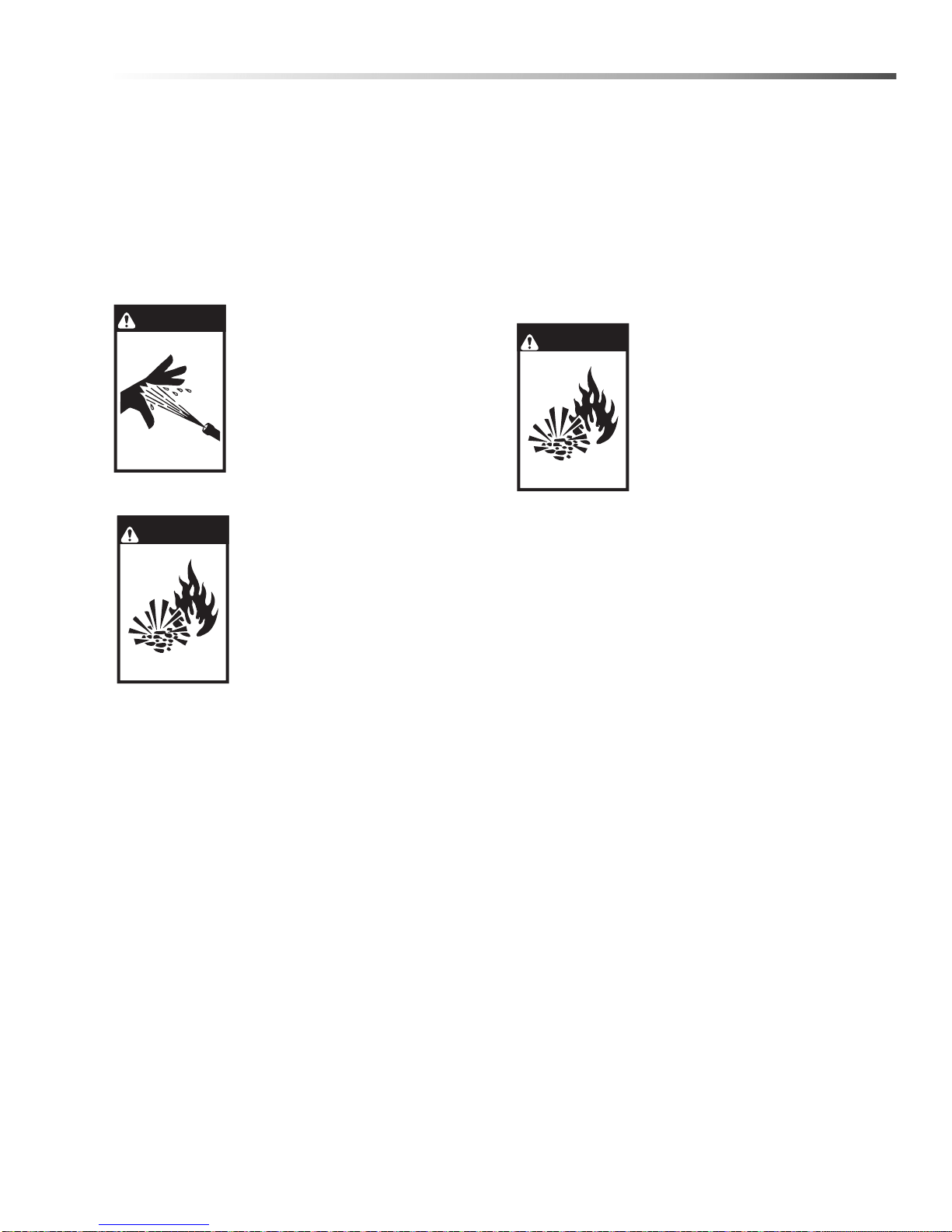
Spanish
ADVERTENCIA
ADVERTENCIA
ADVERTENCIA
ADVERTENCIA: Sostenga la pistona aspersora con
ambas manos ya que con la alta presion esta puede
tener retroceso.
6. Sujete firmemente con ambas manos la varilla
aspersora antes de encender la maq uin a ; de no
seguir esta recomendación puede resultar en
heridas por golpe de la misma.
7. No coloque la máquina cerca de objetos inflamables si el motor esta caliente.
ADVERTENCIA: Este equipo
puede producir un fluido de alta
presion a chorro que puede
penetrar la piel y sus tejidos,
causando graves heridas y
posible amputacion.
8. No reemplazar el tanque
depropano líquido mientras la
unidad está funcionando.
Podrían ocurrir accidentes
serios.
ADVERTENCIA: Usar combustible
líquido solamente.
17. Apagar el quemador, abrir la pistola de paso y
enfriar hasta 100° F antes de apagar la máquina.
18. La máquina no debe estar desatendida durante la
operación.
19. No adecuada para conectar un respiradero de g as
Tipo B, si la temperatura de la chimenea excede
243° C (470° F).
20. Sila máquina va a ser instalada en forma permanente, instalar una campana de tiro con la
descarga de gases fuera del edificio.
Advertencia: Si Se Percibe Olor A
Gas, Cerrar El Suministro De Gas.
21. Si se percibe olor a gas, cerrar el
suministro de gas, apagar toda
llama abierta y revisar las
uniones aplicando una solución
de jabón. Si el olor persiste,
llamar a su proveedor de gas
inmediatamente.
9. Este equipo está diseñado para
funcionar a gas. No usar
combustible líquido. Disponer
de un técnico de servicio calificado para instalar y proveer
servicio de mantenimiento a su
equipo.
10. El agua de ingreso debe estar fría.
11. No operar el equipo cuando se esté fatigado o bajo
la influencia de alcohol o drogas. Mantener el área
de operación libre de personas.
12. Nunca producir chispas o llamas donde exista la
presencia de gas.
13. Nunca intentar encender el piloto a menos que la
válvula manual haya estado cerrada por 5 minutos.
14. Nunca operar la máquina con el tanque de
propano líquido colocado en el soporte. Retirar el
tanque de propano líquido de la máquina tan lejos
como lo permita la manguera.
15. Los gases de propano líquido son más pesados
que el aire y se esparcirán sobre el piso. Proveer
siempre espacio y ventilación adecuados
alrededor de estas unidades.
16. Durante las reparaciones, desconectar el suministro eléctrico y cerrar la válvula de gas.
Landa VHP 2-1500 / 3-2000 Operator’s Manual 8.913-949 .0 - T
41
Page 42

Instalacion
Instalacion
Colocar la máquina en una ubicación conveniente, co n
amplio apoyo, drenaje y espacio para servicio de
mantenimiento.
Este equipo es para uso en interior.
Ubicación:
La ubicación deberá proteger la máquina de las condiciones perjudiciales del medio ambiente, tales como
viento, lluvia y congelamiento.
1. La máquina deberá funcionar en una superficie
nivelada donde no sufra la influencia de factores
externos tales como vientos fuertes, temperaturas
de congelamiento, lluvia, etc. Al seleccionar la
ubicación, considerar accesibilidad para
reemplazar Tanques de propano líquido, reabastecer detergentes, reajustes y mantenimiento. El
operador deberá tomar precauciones par a prevenir
los excesos de humedad que puedan afectar los
componentes eléctricos.
2. Es recomendable hacer una partición entre e l área
de lavado y la máquina para prevenir el rociado
directo de la pistola cuando está en contacto con la
máquina. La humedad excesiva en los controles
eléctricos reducirá la vida útil de la unidad y podr ía
causar cortocircuitos.
3. Durante el montaje, evitar áreas con ventilación
insuficiente o áreas donde los ventiladores
generen insuficiente suministro de oxígeno. Se
puede obtener una buena combustión, solamente
cuando hay suficiente suministro de oxígeno
disponible para la cantidad de combustible incinerado. Si se instala en una área con ventilación
insuficiente, suministrar aire fresco exterior al
quemador con un ventilador instalado dentro del
ambiente. Evitar espacios estrechos o áreas cerca
de ventiladores.
Regulaciones Sobre Gases:
Consultar con la compañía de gas local y con las autoridades municipales respecto a las normas o regulaciones específicas que rijan el montaje. El montaje
debe hacerse de acuerdo con las regulaciones municipales locales.
Aspecto Eléctrico:
El voltímetro VHP2-15021D requiere un receptáculo de
20 amp para cumplir con los estándares de certificación UL 1776.
Respiradero:
Cuando la lavadora a presión es instalada en un
espacio muy estrecho sin aberturas de ventilación al
exterior, deben tomarse medidas para suministrar aire
de combustión a través de aberturas especiales, una
cerca del piso y otra cerca del techo; cada una medida
en base a una pulgada cuadrada o más de área libre
por cada 1,000 BTU de consumo por hora.
Colocación:
No colocar la máquina cerca de materiales combustibles. Mantener todo material inflamable a 20 pies de
distancia por lo menos.
Permitir suficiente espacio para dar servicio de
mantenimiento a la unidad.
Regulaciones municipales locales requieren mantener
ciertas distancias entre el piso y las paredes.
(Dos pies de distancia deberían ser suficientes.)
Suministro de Agua:
El suministro de agua para la unidad deberá ser
provisto por una manguera de jardin de 5/8” de
diámetro interno con una presión de agua local no
menor a 30 psi. Si el suministro de agua es insuficien te,
o si la manguera está torcida, la unidad funcionará mal
y el quemador no arrancará.
Conexión:
Conectar la varilla, boquilla y pistola (como corresponda). En las conexiones de tubería de rosca, usar
cinta de teflón para evitar fugas de agua. (Ver Identificación del Componente.)
Conectar la manguera de alta presión al niple de
descarga jalando el collar de acoplamiento hacia atrás
e insertándolo en el niple de desca rga. Luego, empujar
el collar hacia adelante para asegurarlo. Un inyector
detergente podría ser insertado entre el acoplamiento
de la manguera y el niple de descarga.
Colocar el tubo de productos detergentes en el jabón
líquido o solución detergente. Evitar que el tubo
succione aire.
Esta máquina, al ser instalada, debe ser puesta a tierra
según las regulaciones municipales locales. Verificar el
adecuado suministro de energía usando un vo ltímetro.
42
Landa VHP 2-1500 / 3-2000 Operator’s Manual 8.913-949 .0 - T
PRECAUCION: Al instalar la manguera de
gas propano al Tanque de propano
Page 43
Instalacion
ADVERTENCIA
líquido, por favor, notar que las roscas
están hacia la izquierda.
Inspección y Prueba:
Antes de mantener el gas a presión en las tuberías,
cerrar todas la aberturas por donde pueda escapar el
gas. Inmediatamente después de encender el gas,
debe revisarse el sistema en busca de fugas. Esto
puede hacerse observando el indicador de prueba de
½ pie cúbico y esperando 5 minutos para observar
cualquier movimiento, o aplicando una solución de
jabón a cada conexión de la tubería y observando las
burbujas. Si se detectan fugas, hacer las reparaciones
necesarias y repetir la prueba anterior.
Las tuberías y accesorios defectuosos deben ser
cambiados, no deben ser reparados. Nunca usar
ningún tipo de llama o fuego para localizar fugas de
gas, usar una solución de jabón.
Luego que la tubería y el medidor han sido revisados
completamente, purgar el aire del sistema. NO purgar
el aire dentro de un ambiente cerrado.
La lavadora a presión y la válvula individual de cierre
deben ser desconectados del sistema de tuberías de
suministro de gas durante la prueba de presión donde
una presión sobre ½ psig podría dañar la válvula de
gas.
Válvula de Cierre:
Se ha instalado una válvula de cierre entre la línea de
suministro de gas y la lavadora. La instalación también
incluye una unión entre la válvula de cierre y el
quemador.
Condensación en los Serpentines:
Cuando se bombea agua fría por los serpentines del
calentador y los quemadores están encendidos, se
producirá condensación sobre los serpentines y
goteará al compartimiento del quemador dando la
impresión de fugas en los serpentines, particularmente
en días húmedos y fríos.
Revisar el Serpentín del Calentador de
Agua en busca de Fugas:
Con el quemador “APAGADO” arrancar la unidad de
bombeo y dejar que funcione por unos minutos.
Observar el compartimiento del quemador con una
lámpara o una linterna de mano. Si no se observa
ninguna fuga, el goteo de agua del serpentín será
producto de la condensación de gases combustibles
cuando el quemador está encendido, como se ha
descrito en el párrafo anterior.
Instrucciones
Para El Encendido
ADVERTENCIA: El incumplimiento de las instrucciones
podría resultar en incendio o
explosión causando daños a la
propiedad, accidentes personales o fatales.
1. El equipo tiene un piloto que
puede ser encendido en forma
manual. Al encender el piloto,
seguir éstas instrucciones en
forma estricta.
2. ANTES DE ENCENDER revisar alrededor del
equipo para detectar posible olor a gas. Revisar al
nivel del piso ya que el gas propano es más
pesado que el aire y se acumula sobre el piso.
Para su seguridad: ”¿Qué hacer si se detecta
olor a gas?”
a. No tratar de encender ningún equipo.
b. No tocar ningún interruptor eléctrico; no usar
ningún teléfono del edificio.
c. Llamar inmediatamente a su proveedor de gas
usando un teléfono del vecindario. Seguir las
instrucciones de su proveedor de gas.
d. Si no se puede ubicar a su proveedor de gas,
llamar al departamento de bomberos.
3. 3.Usar solamente la mano para presionar o girar la
perilla de control del gas. Nunca usar herramientas. Si no se puede presionar o girar la perilla
con la mano, no tratar de repararla, llamar a un
técnico de servicio calificado. El uso de fuerza
durante la reparación podría resultar en incendio o
explosión.
4. No usar la máquina cuando una de sus partes ha
estado sumergida en agua. Llamar inmediatamente a un técnico de servicio calificado para
revisar la máquina y reemplazar cualquier parte
del sistema de control o de control de gas que ha
estado sumergida en agua.
Landa VHP 2-1500 / 3-2000 Operator’s Manual 8.913-949 .0 - T
43
Page 44
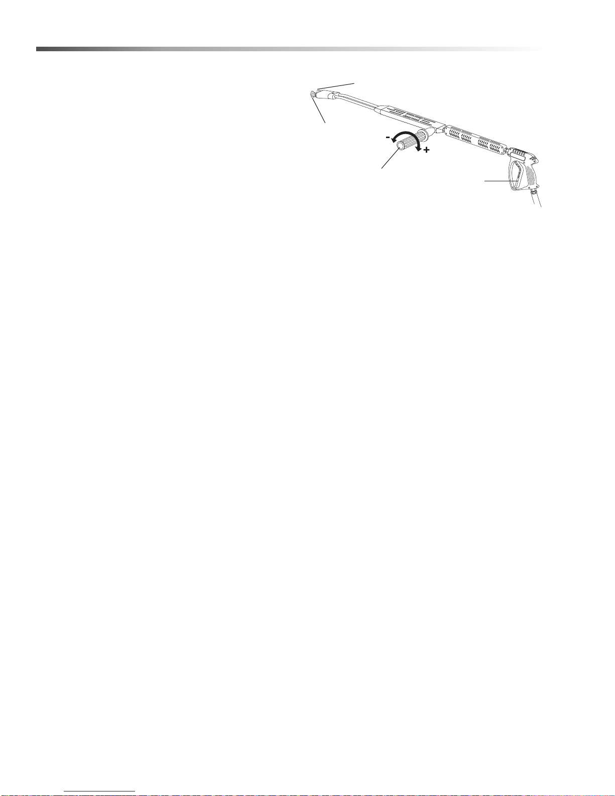
Instrucciones De Operacion
Manija de Control
de Presión Variable
Gatillo
Boquilla
de Alta
Presión
Boquilla de
Bronce para
Jabón
Instrucciones De Operacion
1. ALTO! Leer cuidadosamente el manual del
operador antes de operar esta máquina. El incumplimiento de las instrucciones y advertencias
puede causar una operación defectuosa de la
unidad y puede causar heridas serias y/o daños a
la propiedad.
2. Apagar todos los interruptores.
3. Retirar y colocar el Tanque de propano líquido de
la máquina tan lejos como lo permita la manguera
de suministro.
4. Conectar la manguera de suministro de agua y
abrir el agua. Accionar el gatillo de la pistola de
rociado y dejar fluir agua hasta descargar todo el
aire del sistema. Revisar si hay fugas de agua y
ajustar según sea necesario.
5. Conectar el cable de energía a la conexión
eléctrica apropiada de acuerdo a la información de
la placa de serie. Presionar el botón de reajuste
GFCI. El voltímetro VHP2-15021 D requiere un
receptáculo de 20 amp para cumplir con la certificación UL.
6. Abrir la válvula del Tanque de propano líquido,
luego presionar ligeramente la perilla de la válvula
del control principal de gas que está sobre el
costado derecho de la máquina y girar en dirección
opuesta las agujas del reloj a la posición Piloto.
NOTA: la perilla no puede ser girada de “Piloto” a
“APAGADO” a menos que sea presionada ligeramente.
7. Presionar la perilla de control completamente y
mantenerla en ésa posición. Después de cinco (5)
segundos, presionar el encendedor rojo hasta
escuchar un sonido fuerte. Repetir este paso 3 ó 4
veces, si fuera necesario, hasta encender el piloto.
Si el piloto no enciende, repetir la operación permitiendo un período de tiempo más largo antes de
soltar la perilla de la válvula de gas. Después que
el piloto encienda, continuar manteniendo la perilla
de control hacia abajo aproximadamente po r un (1)
minuto antes de soltarla. Observar la mirilla del
piloto en la parte posterior de la máquina.
9. Para operar con agua fría, girar el interruptor a la
posición de la bomba y accionar el gatillo de la
pistola de rociado.
• Asegure la boquilla de alta presión en el ex
tremo de la varilla.
• Gire la manilla para ajustar la presión.
• Para aplicar detergente debe usarse baja
presión.
• Lea el manual para operar, previamente.
10. Para operar con agua caliente, girar el interru ptor a
la posición del quemador y accionar el gatillo de la
pistola de rociado.
11. Para aplicar detergente, leer las instrucciones
sobre el uso del inyector detergente.
12. Para Detener: limpiar las líneas de productos
detergentes con agua fresca, cambiar a la posición
de la bomba y continuar rociando agua hasta
enfriar el quemador.
13. Después que el agua se ha enfriado, apagar la
bomba. Apagar la llave principal de gas, luego
cerrar la válvula del Tanque de propano líquido.
Revisar que el Tanque de propano líquido esté fijo
a la máquina cuando ésta sea transportada.
14. Cerrar el agua. Para protección contra el congelamiento, accionar el gatillo de la pistola de rociado
para drenar el agua del sistema.
Para Usar Vapor:
(Modelo VHP3-70021D solamente)
8. Girar la perilla de control de gas en el sentido
opuesta a las agujas del reloj hasta el punto de
“ENCENDIDO.”
44
Landa VHP 2-1500 / 3-2000 Operator’s Manual 8.913-949 .0 - T
1. Girar la perilla del control en descargador en el
sentido opuesta a las agujas del reloj. Esto reduce
el fluir del agua por el serpentín.
2. La presión del agua disminuirá aproximadamente
a 250 psi y la temperatura aumentará aproximadamente 250° F.
3. Después de usar vapor, girar la perilla del control
en el descargador en el sentido de la agujas del
Page 45

Mantenimiento
reloj hasta que pare. Bajará la temperat ur a. Ante s
de apagar la lavadora, dejar que funcione sin
prender el quemador para enfriar el serpentín.
Mantenimiento Y Servicio
Mantenimiento Preventivo
1. Revisar si la bomba de agua está lubricada apropiadamente.
2. Seguir las instrucciones para acondic ion a mie n to
de invierno y prevenir daños por congelamiento de
la bomba y los serpentines.
3. Siempre neutralizar y limpiar después de usar
productos detergentes en el sistema.
4. Si el agua tiene alto contenido de minerales, usar
un ablandador de agua o eliminador de escamas
en el sistema, según sea necesario.
5. No permitir que líquidos ácidos, caústicos o
abrasivos sean bombeados a través del sistema.
6. Siempre usar productos de limpieza de alta calidad
Landa.
7. Nunca hacer funcionar la bomba en seco por
extensos períodos de tiempo.
8. Periódicamente, limpiar los depósitos de cal de los
serpentines según las instrucciones.
Se aconseja inspeccionar regularmente, el quemador
en forma visual. Revisar el ingreso de aire para
asegurar que no esté atascado o bloqueado. Limpiar
todos los derrames de aceite y mantener la máquina
limpia y seca.
Las áreas alrededor de la lavadora Landa deberán
mantenerse limpias y libres de materiales combustibles, gasolina y otros líquidos inflamables.
Procedimiento de Acondicionamiento para
el Invierno:
El daño debido al congelamiento no está cubierto por la
garantía. Respetar los siguientes procedimientos para
el clima frío siempre que la lavadora deba almacenarse
u operarse a la intemperie bajo condiciones de congelamiento.
Durante los meses de invierno, cuando la temperatura
baja a menos de 32° F, se debe proteger la máquina
del congelamiento según sea necesario. Almacenar la
máquina en un ambiente con calefacción. Si ésto no es
posible, mezclar una solución 50/50 de anticongelante/
agua en un depósito de 5 galones. Colocar una sección
corta de manguera de jardin en el d epósito y conectar a
la máquina. Elevar el depósito y prender la bomba para
sifonear el anticongelante a la máquina. Si se dispone
de aire comprimido, puede instalarse un accesorio de
aire al conector de entrada y todo el agua será
evacuada fuera del sistema.
Termostato de Control de Agua Caliente:
Para seguridad, cada unidad está equipada con un
interruptor de control de temperatura. Si la temperatu ra
del agua excede la temperatura de operación, el
control apagará el quemador hasta qu e el ag u a se
enfríe.
Bombas:
Usar solamente aceite no-detergente SAE 10W-40.
Cambiar el aceite después de las primeras 50 horas de
uso. Luego, cambiar el aceite cada tres meses o en
intervalos de 500 horas. El nivel de aceite debe ser
revisado usando la varilla de medir ubicada en la
bomba o el punto rojo visible a través de la ventana del
calibrador. El aceite debe mantenerse en ése nivel.
El flujo de combustión y aire de ventilación al
quemador no deben ser obstruídos o bloqueados de
ninguna manera.
Mantenimiento Y Servicio
Válvulas de Descarga:
Las válvulas de descarga liberan la presión en la línea
cuando la pistola de rociado está cerrada. La válvulas
de descarga son programadas y verificadas antes de
salir de fábrica. Ocasionalmente, deben regularse para
mantener la presión correcta. (Ver la sección del
manual sobre válvulas de descarga para el procedimiento correcto de regulación de la válvula.)
Landa VHP 2-1500 / 3-2000 Operator’s Manual 8.913-949 .0 - T
Limpieza de Serpentines:
En áreas de agua alcalina, los depósitos de cal pueden
acumularse en los serpentines rápidamente. Estos
depósitos se incrementarán con la alta temperatura
generada en los serpentines. La mejor prevención para
la sedimentación es usar productos de limpieza de alta
calidad. En áreas donde el agua alcalina es un
problema, el uso regular de Polvo eliminador de cal
Landa (parte #9-028008) limpiará la cal y otros sedimentos antes que obstruyan el serpentín.
45
Page 46

Mantenimiento
Eliminador de cal de Serpentines:
Se recomienda un lavado periódico de los serpentines.
1. Llenar un depósito con 4 galones de agua y luego
añadir 1 libra de polvo desincrustante. Mezclar
completamente.
2. Retirar la varilla de la pistola y colocar la pistola en
un depósito. Asegurar que el gatillo de la pistola
esté en posición abierta.
3. Unir una sección corta (3-5 pies) de manguera de
jardin a la máquina para sifonear la solución hacia
un depósito elevado. Encender la bomba para que
la solución sea bombeada a través de los serpentines de regreso al depósito. La solución deberá
circular por 2-4 horas.
4. Después de hacer circular la solución, lavar todo el
sistema con agua fresca. Reinstalar la varilla en la
pistola.
Remoción de Hollín del Serpentín de
Calentamiento:
Durante el proceso de calentamiento pueden producirse residuos de combustible en forma de ho llín en tr e
los serpentines de calentamiento, bloquear el flujo de
aire y afectar la combustión del quemador. Cuando se
observe hollín, debe limpiarse después de seguir los
pasos para desmontar el serpentín.
Capacidad del Cilindro de Gas Propano:
Una importante consideración con los sistemas de gas
propano, es la capacidad del cilindro de suministro en
relación a las necesidades del quemador. El quemador
opera con gas propano del cilindro, el líquido del
cilindro ebulle para mantener la presión del gas. Este
proceso de ebullición enfría el líquido y, en una
situación de demanda continua y exigente, la temperatura del líquido puede disminuir a un punto que no
puede suministrar gas tan rápido como se r equiere. En
este caso, podría ser necesario calentar el Cilindro de
Gas Propano rociando agua caliente que no exceda
120° F, sobre el cilindro frío o al colocar dos botellas de
gas propano juntas para incrementar la capacida d total
de vaporización. Se recomienda usar una botella de
gas propano de 30 libras de capacidad en la unidad.
1. Retirar el ensamble del tanque destornillando los
tres tornillos Tek y levantando el cabezal del
tanque.
2. Retirar los dos niples de la tubería y los accesorios
correspondientes.
3. Levantar el serpentín fuera de la envoltura exterior.
PRECAUCION: El serpentín pesa casi 80 libras.
Usar técnicas de levantamiento apropiadas.
4. Limpiar, reparar y reemplazar el serp en tín
siguiendo los pasos anteriores pero a la inversa.
Válvula de Alivio de Presión:
Cada unidad está equipada con una válvula de alivio
de presión para descargar la presión del sistema
cuando se detectan presiones de operación más altas
de lo normal. Las altas presiones inusitadas provienen
de algún objeto que obstruye la boquilla de rociado.
Este problema se puede remediar fácilmente al retirar
la obstrucción. Si la presión de operación de la unidad
es normal y la válvula de alivio sigue con fugas, reparar
o reemplazar la válvula.
46
Landa VHP 2-1500 / 3-2000 Operator’s Manual 8.913-949 .0 - T
Page 47

Mantenimiento
Uso del Inyector de Productos
Detergentes
ADVERTENCIA: Algunos productos detergentes
pueden ser dañinos cuando se los inhala o ingiere,
causar náuseas, desmayo o envenenamiento
agudo. Los elementos dañinos pueden causar
daño a la propiedad o lesiones graves.
El conjunto de inyectores para productos detergentes
de Landa se puede utilizar para hacer sifón y mezclar
los detergentes.
1. Apague el motor y cierre la entrada de agua.
Antes de acoplar el inyector de productos detergentes, abra la pistola de rociado para aliviar la
presión.
2. Para acoplar el inyector de productos detergentes
entre la unidad de lavado a presión y la mangue ra
de alta presión, tire del cuello del acoplador de
conexión rápida del inyector hacia atrás y coloque
el manguito de unión de descarga. La flecha de la
válvula de inyección debe apuntar en la dirección
del flujo.
3. Conecte la manguera de descarga de presión al
manguito de unión de inyección con el acoplador
de conexión rápida. Empuje el cuello del acoplador
hacia el manguito de unión.
NOTA: El inyector para los productos detergentes no
puede hacer sifón cuando la manija de control, de la
extensión de presión variable, se encuentra en
posición de alta presión.
4. Haga arrancar la unidad tal como se describe en
las Instrucciones para operar la unidad.
5. Coloque el tubo de aspiración para el producto
detergente en el recipiente de la solución detergente.
6. Instale la boquilla para detergente en el acople
rápido.
7. Abra la pistola a gatillo. La proporción de agua y
del producto detergente es de aproximadamente
15 a 1.
8. Para limpiar, coloque el tubo para el producto
detergente en un recipiente con agua limpia y siga
los pasos 5 y 7 para evitar que los depósitos detergentes dañen el inyector.
9. Si la unidad cuenta con una extensión de presión
variable; para limpiar, alivie la presión haciendo
girar la manija para el control de presión en sentido
contrario a las agujas del reloj. Esto dirige el flujo
de agua a través de la boquilla de jabón y permite
que el inyector del producto detergente succione el
jabón. Para enjuagar con agua a alta presión,
simplemente gire la manija de control en la
dirección de las agujas del reloj.
Landa VHP 2-1500 / 3-2000 Operator’s Manual 8.913-949 .0 - T
47
Page 48
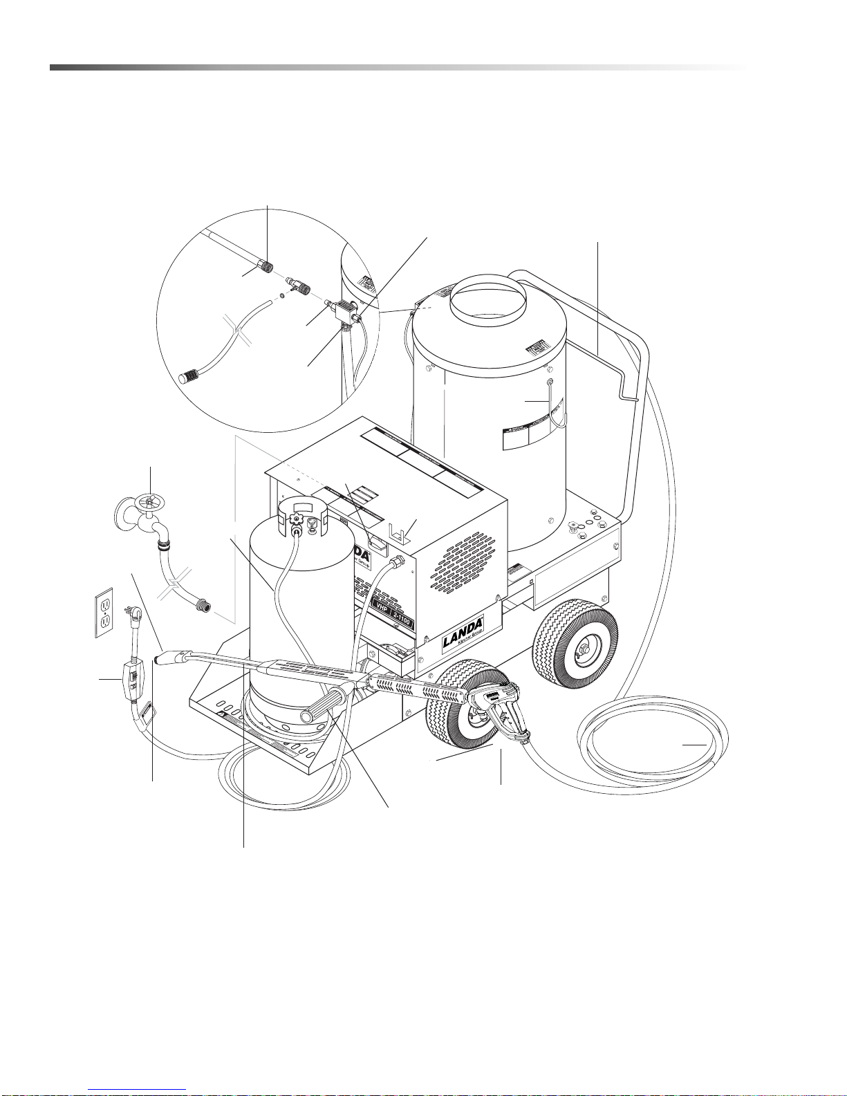
Identificacion de Componentes
Tanque
de Gas
Propano
(no se
incluye)
Colgador de
Manguera de
Alta Presión
Manija de Control
de Presión Variable
Varilla de Presión
Variable
Boquilla de Alta
Presión
Boquilla de
Bronce para
Jabón
Disco de Alta
Presión
Niple de
Descarga
Interruptor de
Resorte de
Límite Alto
Inyector
Detergente
Acoplamiento
Rápido
Interruptor
de Bomba &
Quemador
Sostén de
la Varilla
Manguera
de Alta
Presión
Gatillo
Pistola de
Rociado
GFCI
Manguera
de Gas
Propano
Manguera de
Suministro de
Agua (no se
incluye)
Colgador
de Varilla
48
Landa VHP 2-1500 / 3-2000 Operator’s Manual 8.913-949 .0 - T
Page 49

Nota
Landa VHP 2-1500 / 3-2000 Operator’s Manual 8.913-949 .0 - T
49
Page 50

®
8.913-949.0 • Printed in U.S.A.
 Loading...