

Page 1
®
PGDC
GAS
8.91
6-274.
0
DIESEL
8.932-96
0.
0
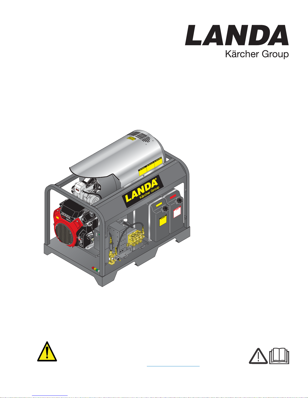
Hot Water - Gasoline Powered - Diesel/Oil Heated
Operator’s Manual
Pressure Washer
MODELS:
PGDC4 - 3500
1.110-049.0
PGDC5 - 3500
1.110-050.0
PGDC5 - 3500
1.110-051.0
PGDC8 - 3000
1.110-072.0
WARNING:
This product and accessories contains a chemical known to the
State of California to cause cancer, birth defects or other
reproductive harm.
For more information about this regulation: www.P65Warnings.ca.gov
For the Landa Dealer nearest
you, consult our web page at
www.landa.com
8.916-596.0-P 08/16/17
Page 2
Machine Data Label
2 Landa PGDC Operator’s Manual 8.916-596.0 - P
Page 3

Machine Data Label. . . . . . . . . . . . . . . . . . . . . . . . . .2
Table of Contents . . . . . . . . . . . . . . . . . . . . . . . . . . .3
How To Use This Manual . . . . . . . . . . . . . . . . . . . . .4
Safety
Introduction & Safety Information . . . . . . . . . . . . . . .5
Important Safety Information. . . . . . . . . . . . . . . . . . .6
Operations
Component Identification . . . . . . . . . . . . . . . . . . . . .9
Assembly Instructions. . . . . . . . . . . . . . . . . . . . . . .10
Battery Installation . . . . . . . . . . . . . . . . . . . . . . . . .10
Operation Instructions. . . . . . . . . . . . . . . . . . . . . . .11
Detergents & General Cleaning Techniques . . . . .12
Shutting Down And
Clean-up . . . . . . . . . . . . . . . . . . . . . . . . . . . . . . .13
Maintenance
Storage . . . . . . . . . . . . . . . . . . . . . . . . . . . . . . . . . .14
Engine Maintenance. . . . . . . . . . . . . . . . . . . . . . . .14
Landa Sure Fire Oil Burner. . . . . . . . . . . . . . . . . . .17
Troubleshooting . . . . . . . . . . . . . . . . . . . . . . . . . . .18
Preventative Maintenance . . . . . . . . . . . . . . . . . . .22
Maintenance Schedule . . . . . . . . . . . . . . . . . . . . . .22
Oil Change Record . . . . . . . . . . . . . . . . . . . . . . . . .23
Table of Contents
Parts
Landa PGDC. . . . . . . . . . . . . . . . . . . . . . . . . . . . . 26
Landa PGDC. . . . . . . . . . . . . . . . . . . . . . . . . . . . . 28
Power Platform . . . . . . . . . . . . . . . . . . . . . . . . . . . 30
Control Box. . . . . . . . . . . . . . . . . . . . . . . . . . . . . . 33
Coil . . . . . . . . . . . . . . . . . . . . . . . . . . . . . . . . . . . . 34
Option, Float Tank . . . . . . . . . . . . . . . . . . . . . . . . 36
Hose & Spray Gun . . . . . . . . . . . . . . . . . . . . . . . . 38
Burner. . . . . . . . . . . . . . . . . . . . . . . . . . . . . . . . . . 39
Unloader - 4-3500, 5-3500 . . . . . . . . . . . . . . . . . . 40
Unloader - 8-3000. . . . . . . . . . . . . . . . . . . . . . . . . 41
Pump. . . . . . . . . . . . . . . . . . . . . . . . . . . . . . . . . . . 42
Specifications . . . . . . . . . . . . . . . . . . . . . . . . . . . . 43
Landa Sure Fire Burner . . . . . . . . . . . . . . . . . . . . 44
LT.2 Series Pump . . . . . . . . . . . . . . . . . . . . . . . . . 48
VRT3 Unloader. . . . . . . . . . . . . . . . . . . . . . . . . . . 50
Landa PGDC Operator’s Manual 8.916-596.0 - P
3
Page 4

How To Use This Manual
Model:
Date of Purchase:
Serial Number:
Dealer:
Address:
Phone Number:
Sales Representative:
This manual contains the following sections:
• How to Use This Manual
•Safety
• Operations
• Maintenance
• Parts List
The HOW TO USE THIS MANUAL section will tell you
how to find important information for ordering correct
repair parts.
Parts may be ordered from authorized dealers. When
placing an order for parts, the machine model and
machine serial number are important. Refer to the
MACHINE DATA box which is filled out during the
installation of your machine. The MACHINE DATA box
is located on the inside of the front cover of this manual.
The model and serial number of your machine is
located on the back of the machine.
The SAFETY section contains important information
regarding hazardous or unsafe practices of the
machine. Levels of hazards are identified that could
result in product damage, personal injury, or severe
injury resulting in death.
The OPERAT IONS section is to familiarize the operator
with the operation and function of the machine.
The MAINTENANCE section contains preventive maintenance to keep the machine and its components in
good working condition. They are listed in this general
order:
• Storage
• Engine Maintenance
• Landa Sure Fire Oil Burner
• Troubleshooting
• Preventative Maintenance
• Oil Change Record
The PARTS LIST section contains assembled parts
illustrations and corresponding parts list. The parts lists
include a number of columns of information:
• REF – column refers to the reference number
on the parts illustration.
• PART NO. – column lists the part number for
the part.
• QTY – column lists the quantity of the part used
in that area of the machine.
• DESCRIPTION – column is a brief description
of the part.
• NOTES – column for information not noted by
the other columns.
NOTE: If a service or option kit is installed on your
machine, be sure to keep the KIT INSTRUCTIONS
which came with the kit. It contains replacement parts
numbers needed for ordering future parts.
4
Landa PGDC Operator’s Manual 8.916-596.0 - P
NOTE: The manual part number is located on the
lower right corner of the front cover.
Page 5

Introduction & Safety Information
Thank you for purchasing this Pressure Washer. We
reserve the right to make changes at any time
without incurring any obligation.
Owner/User Responsibility:
The owner and/or user must have an understanding of
the manufacturer’s operating instructions and warnings
before using this pressure washer . Warning in formation
should be emphasized and understood. If the operator
is not fluent in English, the manufacturer’s instructions
and warnings shall be read to and discussed with the
operator in the operator’s native language by the
purchaser/owner, making sure that the operator
comprehends its contents.
Owner and/or user must study and maintain for future
reference the manufacturers’ instructions.
The operator must know how to stop the machine
quickly and understand the operation of all controls.
Never permit anyone to operate the engine without
proper instructions.
Safety
SAVE THESE INSTRUCTIONS
This manual should be considered a permanent
part of the machine and should remain with it if
machine is resold.
When ordering parts, please spec if y mo de l and
serial number. Use only id entical replacement
parts.
This machine is to be used only by trained operators.
Landa PGDC Operator’s Manual 8.916-596.0 - P
5
Page 6
Safety
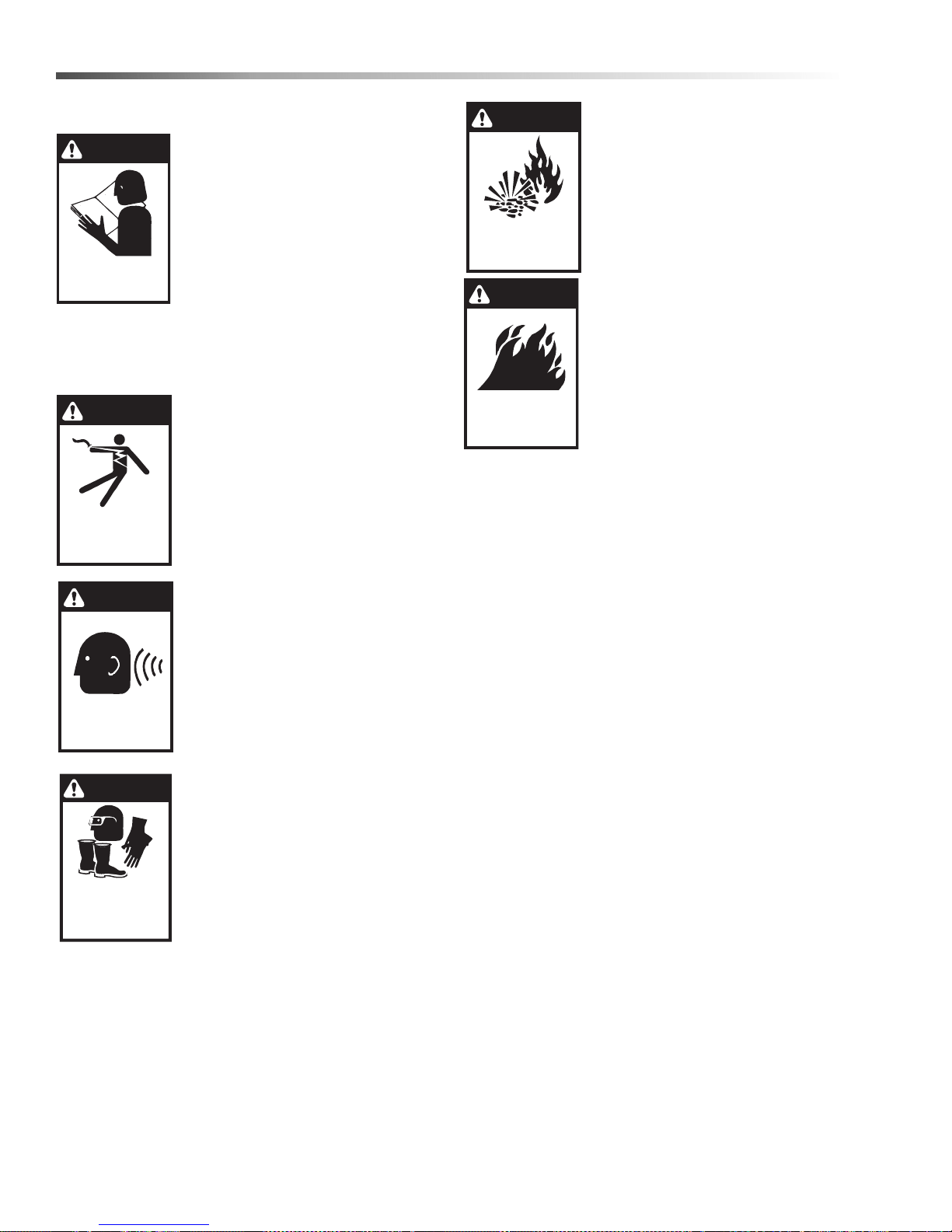
WARNING
DANGER
KEEP WATER
SPRAY AWAY FROM
ELECTRICAL WIRING.
WARNING
EAR PROTECTION
MUST BE WORN
WARNING
USE PROTECTIVE
EYE WEAR
AND CLOTHING
WHEN OPERATING
THIS EQUIPMENT.
WARNING
RISK OF EXPLOSION:
OPERATE ONLY WHERE
OPEN FLAME OR TORCH
IS PERMITTED
WARNING
RISK OF FIRE.
DO NOT ADD FUEL
WHEN OPERATING
MACHINE.
Important Safety Information
WARNING: To reduce the risk of
injury, read operating instructions
carefully before using.
SAFETY
OPERATIONS
MAINTENANCE
READ OPERATOR’S
MANUAL THOROUGHLY
PRIOR TO USE.
2. Know how to stop the machine and bleed pressure
quickly. Be thoroughly familiar with the controls.
3. Stay alert — watch what you are doing.
1. Read the owner's manual thoroughly. Failure to follow instructions could cause malfunction of
the machine and result in death,
serious bodily injury and/or
property damage.
DANGER: Keep wand, hose, and
water spray away from electric
wiring or fatal electric shock may
result.
4. All installations must comply with
local codes. Contact your electrician, plumber, utility company or
the selling distributor for specific
details.
WARNING: This machine exc eeds
85 db appropriate ear protection
must be worn.
WARNING: Flammable liquids
can create fumes which can
ignite, causing property damage
or severe injury.
WARNING: Risk of explosion —
Operate only where open flame or
torch is permitted.
WARNING: Risk of fire — Do not
add fuel when the product is
operating or still hot.
WARNING: Do not use gasoline
crankcase draining or oil
containing gasoline, solvents or
alcohol. Doing so will result in fire
and/or explosion.
WARNING: Risk of fire — Do not
Spray flammable liquids.
7. Allow engine to cool for 1-2 minutes before refueling. If any fuel is spilled, make sure the area is
dry before testing the spark plug or starting the
engine. (Fire and/or explosion may occur if this is
not done.)
Gasoline engines on mobile or portable equipment
shall be refueled:
WARNING: High pressure spray
can cause paint chips or other
particles to become airborne and
fly at high speeds. To avoid
personal injury, eye, hand and
foot safety devices must be worn.
5. Always wear properly rated eye
protection such as safety
goggles or face shield while
spraying.
(Safety glasses do not provide full protection.)
6. Keep operating area clear of all persons.
a. outdoors;
b. with the engine on the equipment stopped;
c. with no source of ignition within 10 feet of the
dispensing point; and
d. with an allowance made for expansion of the
fuel should the equipment be exposed to a
higher ambient temperature.
In an overfilling situation, additional precautions
are necessary to ensure that the situation is
handled in a safe manner.
WARNING: Risk of injury. Disconnect battery
ground terminal before servicing.
8. When in use, do not place machine near
flammable objects as the engine is hot.
9. Oil burning appliances shall be installed only in
locations where combustible dusts and flam m abl e
gases or vapors are not present. Do not store or
use gasoline near this machine.
6
Landa PGDC Operator’s Manual 8.916-596.0 - P
Page 7
Safety
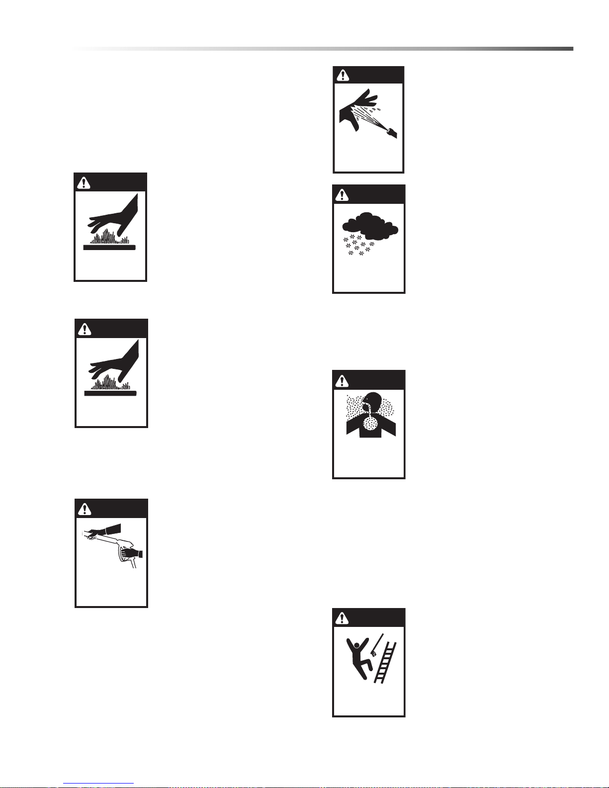
WARNING
RISK OF INJURY.
HOT SURFACES
CAN CAUSE BURNS
WARNING
HOT DISCHARGE FLUID:
DO NOT TOUCH OR
DIRECT DISCHARGE
STEAM AT PERSONS.
WARNING
TRIGGER GUN KICKS
BACK — HOLD WITH
BOTH HANDS
WARNING
RISK OF INJECTION
OR SEVERE INJURY
TO PERSONS. KEEP
CLEAR OF NOZZLE.
WARNING
PROCTECT FROM
FREEZING
WARNING
RISK OF INJURY
FROM FALLS WHEN
USING LADDER.
RISK OF
ASPHYXIATION.
USE THIS PRODUCT
ONLY IN A WELL
VENTILATED AREA.
DANGER
10. Use No. 1 or No. 2 heating oil (ASTM D306) only.
NEVER use gasoline in your fuel oil tank. Gasoline
is more combustible than fuel oil and could result in
a serious explosion. NEVER use crankcase or
waste oil in your burner . Fuel unit malfunction could
result from contamination.
11. Do not confuse gasoline and fuel oil tanks. Keep
proper fuel in proper tank.
WARNING: Risk of injury. Hot
surfaces can cause burns. Use
only designated gripping areas of
spray gun and wand. Do not place
hands or feet on non-insulated
areas of the pressure washer.
12. Transport/Repair with fuel tank EMPTY or with fuel
shut-off valve OFF.
CAUTION: Hot discharge fluid. Do
not touch or direct discharge
stream at persons.
WARNING: This machine
produces hot water and must
have insulated components
attached to protect the operator.
13. To reduce the risk of injury, close supervision is
necessary when a machine is used near children.
Do not allow children to operate the pressure
washer. This machine must be attended during
operation.
WARNING: Grip cleaning wand
securely with both hands before
starting. Failure to do this coul d
result in injury from a whipping
wand.
14. Never make adjustments on
machine while in operation.
WARNING: High pressure
developed by these machines will
cause personal injury or
equipment damage. Keep clear of
nozzle. Use caution when operating. Do not direct discharge
stream at people and animals, or
severe injury or death will result.
WARNING: Protect machine from
freezing.
16. To keep machine in best
operating conditions, it is
important you protect machine
from freezing. Failure to protect
machine from freezing could
cause malfunction of the
machine and result in death,
serious bodily injury, and/or
property damage. Follow storage instructions
specified in this manual.
17. Inlet water must be clean fresh water and no hotter
then 90°F.
DANGER: Risk of asphyxiation.
Running this product indoors
can result in death due to carbon
monoxide, poison gas you cannot
see or smell. Only use outdoors
and far away from windows,
doors, and openings or vents.
Use this product only in a well
ventilated area.
18. Avoid installing machines in
small areas or near exhaust fans. Adequate
oxygen is needed for combustion or dangerous
carbon monoxide will result.
19. Manufacturer will not be liable for any changes
made to our standard machines or any components not purchased from us.
20. The best insurance against an accident is precaution and knowledge of the machine.
15. Be certain all quick coupler fittings are secured
before using pressure washer.
Landa PGDC Operator’s Manual 8.916-596.0 - P
WARNING: Be extremely careful
when using a ladder, scaffolding
or any other relatively unstable
location. The cleaning area should
have adequate slopes and
drainage to reduce the possibility
of a fall due to slippery surfaces.
7
Page 8
Safety
WARNING
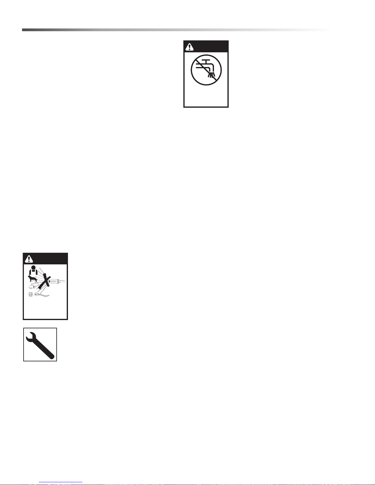
DO NOT SPRAY
MACHINE OR ANY
PEOPLE, ANIMALS OR
ELECTRICAL PARTS.
WARNING
NOT SUITABLE
FOR CONNECTION
TO THE POTABLE
WATER MAINS.
21. Do not allow acids, caustic or abrasive fluids to
pass through the pump.
22. Never run pump dry or leave spray gun closed
longer than 1-2 minutes.
23. Machines with shut-off spray gun should not be
operated with the spray gun in the off position for
extensive periods of time as this may cause
damage to the pump.
24. Protect discharge hose from vehicle traffic and
sharp objects. Inspect condition of high pressure
hose before using or bodily injury may result.
25. Before disconnecting discharge hose from water
outlet, turn burner off and open spray gun to allow
water to cool below 100° before stopping the
machine. Then open the spray gun to relieve
pressure. Failure to properly cool down or maintain
the heating coil may result in a steam explosion.
26. Do not overreach or stand on unstable support.
Keep good footing and balance at all times.
27. Do not operate this machine when fatigued or
under the influence of alcohol, prescription medications, or drugs.
WARNING: If connection is made
to a potable water system, the
system shall be protected against
back flow.
28. In oil burning models, use only kerosene, No. 1
home heating fuel, or diesel. If diesel is used, add a
soot remover to every tankful.
WARNING: Do not spra y machine
or any people, animals or electrical parts.
Follow the maintenance instructions
specified in the manual.
8
Landa PGDC Operator’s Manual 8.916-596.0 - P
Page 9
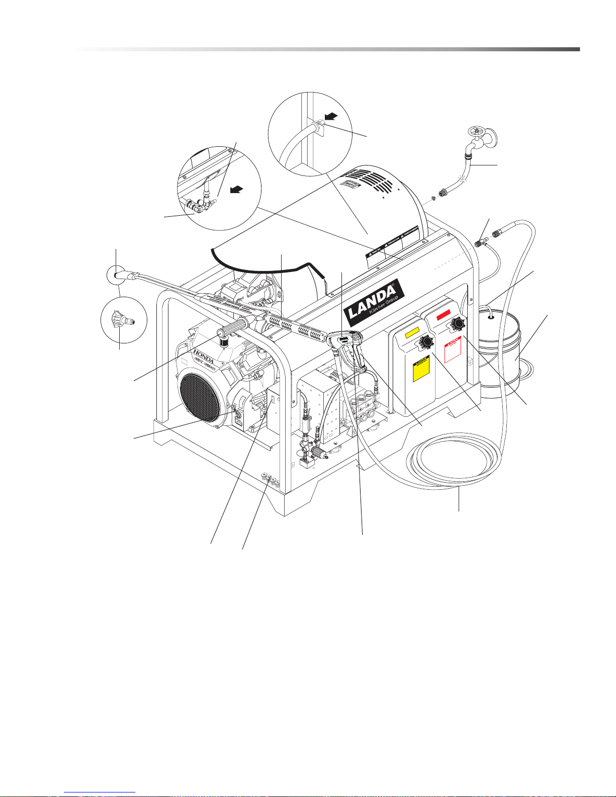
Component Identification
Detergent
Pick Up
Tube
Water Supply
Hose (not
included)
Detergent
Bucket
(not included)
High Pressure
Hose
Fuel Oil
Tank
Variable
Pressure
Control
Wand Handle
Variable Pressure
Control Wand
Nozzle
Engine
Switch
Spray
Gun
Nozzle
Quick
Coupler
Discharge
Nipple
Rupture
Disk
Gasoline
Tank
Pressure
Nozzles
Burner
Switch
Trigger
Fresh
Water
Inlet
Detergent
Injector
(not included)
Trigger
Safety Latch
8.932-960.0
DIESEL
Operations
.0
S
74
-2
16
8.9
GA
Landa PGDC Operator’s Manual 8.916-596.0 - P
9
Page 10
Operations
Spray Wand
Saf
Latch
Spra
Gun
High Pressure
Hose
GA
S
8.
91
6-27
4.0
DIESEL
8.932-
9
6
0.
0
High
Pressure
Hose
Discharge
Nipple
GA
S
8.91
6-2
74.
0
DIESEL
8.932-960.0
Gasoline
Burner Fuel
SHIELD
EYES
EXPLOSIVE
GASES
CAN CAUSE
BLINDNESS OR INJURY
NO
SPARKS
FLAMES
SMOKING
SULFURIC
ACID
CAN CAUSE
BLINDNESS OR
SEVERE BURNS
FLUSH EYES
IMMEDIATELY
WITH WATER
GET
MEDICAL
HELP
FAS T
KEEP OUT OF THE REACH OF CHILDREN. DO NOT TIP
. KEEP VENT CAPS TIGHT AND LEVEL.
DANGER/POISON
Bla
ck - Negative
T
erminal
Red + Positive
Terminal
Blac
k
Red
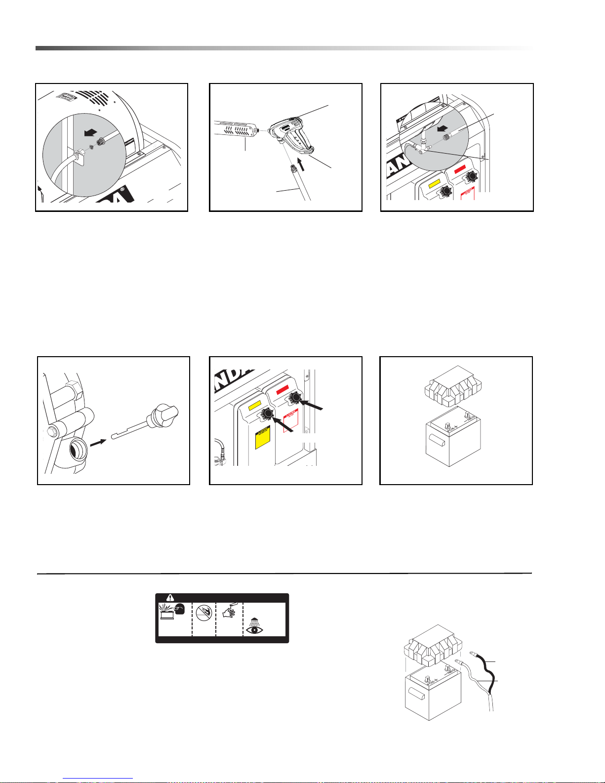
Assembly Instructions
ety
y
STEP 1: Attach a 5/8" water supply
hose to inlet connector. Minimum
flow should be 6 or 10 gpm
depending on model of machine.
STEP 4: Check engine and pump
oil level by removing oil dipstick,
making sure oil is on proper
indicator marking. Oil should be
visible one half way up sight glass
located at the end of pump
(SAE 10W-40 non-foaming).
STEP 2: Attach wand to spray gun
using teflon tape on threads to
prevent leakage. Attach swivel
connector on discharge hose to
spray gun using teflon tape on
threads. Attach swivel connector on
high pressure hose to spray gun
using teflon tape on threads.
Engage safety latch to prevent from
triggering gun when inserting high
pressure nozzle.
STEP 5: Fill red gasoline tank. Fill
green fuel oil tank. Do not confuse
gasoline and fuel oil (diesel) tanks.
Keep proper fuel in proper tank.
STEP 3: Attach high pressure hose
to discharge nipple using quick
coupler. Lock coupler securely into
place by pulling back coupler collar
and inserting it into discharge
nipple, then pushing collar forward
to lock in place.
STEP 6: Install proper battery
making sure that the red cable is
attached to the positive terminal.
Use a 12V Group 24 battery on all
models except 4-40321 and 535321E. These models use a U1
30 amp garden tractor style battery.
Battery Installation
Due to Federal Regulations concerning shipment
of corrosive chemicals,
batteries are not shipped
with this machine.
Local purchase of battery will be the responsibility of
the owner. Automotive type 12 Volt Group 24 battery is
resistant box. Follow safety and installation instructions
furnished with the battery.
10
recommended for placement within the weather
Landa PGDC Operator’s Manual 8.916-596.0 - P
Red Cable is attached to battery (+) positive terminal,
black cable is connected to battery (-) negative
terminal.
Page 11
Operation Instructions
High Pressure
Nozzle
Wand
Coupler
Collar
Engine
Switch
Burner
Switch
Detergent
Valve
Variable Pressure
Control Handle
Trigger
Variable Pressure
Wand (VP)
High
Pressure
Nozzle
Brass Soap
Nozzle
Operations
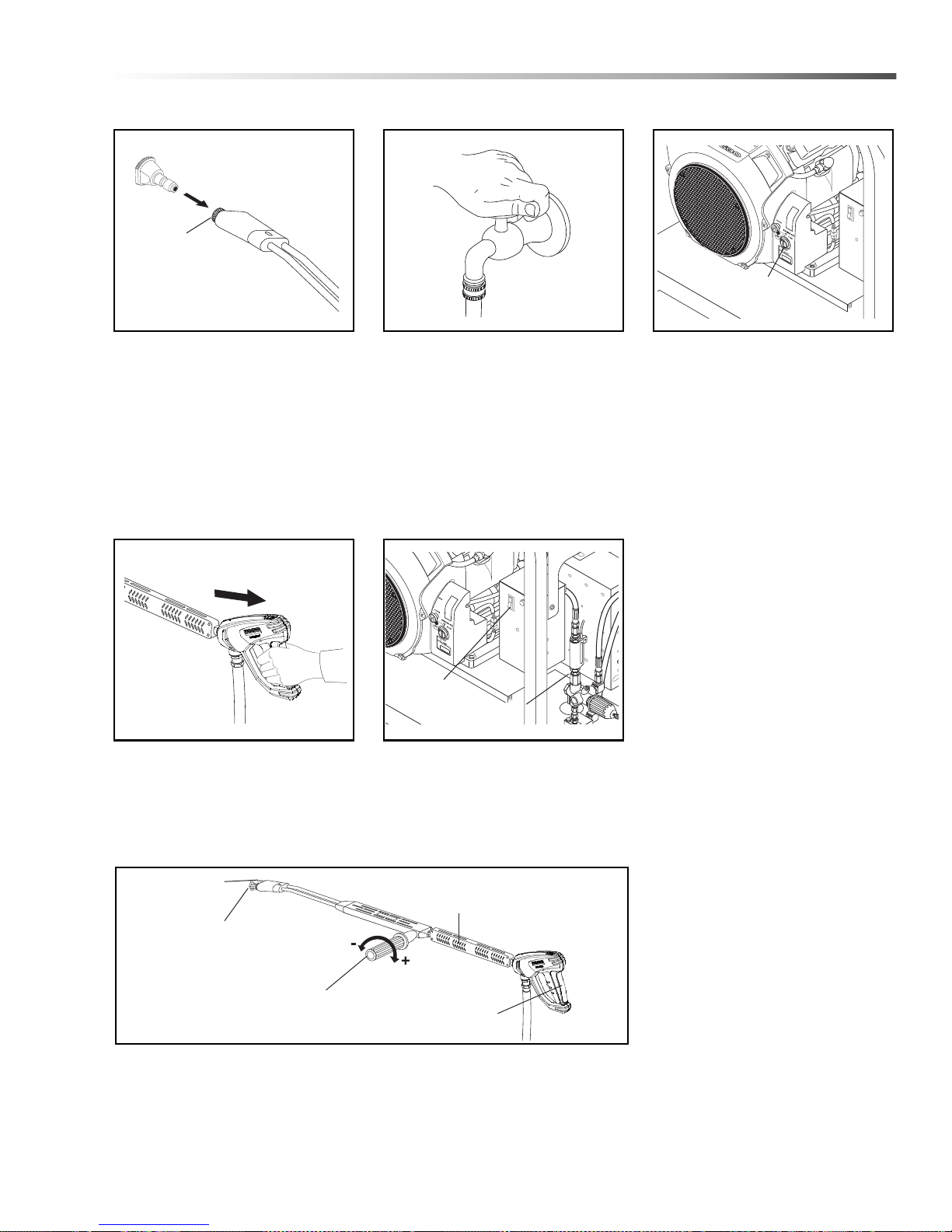
STEP 1: Read operator’s manual
before operating. Pull wand coupler
collar back, insert desired pressure
nozzle into coupler, then secure by
pushing collar forward.
CAUTION: Never replace nozzles
without engaging the safety
latch on the spray gun trigger.
STEP 4: With the spray nozzle
pointed away from you or anybody
else, press the trigger on the spray
gun to obtain pressurized cold
water spray.
STEP 2: Turn on water at faucet
and pull trigger on spray gun
allowing water to flow until all air
has discharged from system.
Check for water leaks; tighten as
needed. NOTE: Variable pressure
control wand handle must be
turned clockwise to enable water to
flow out of the high pressure
nozzle.
STEP 5: For hot water, turn the
burner switch to ON when a steady
stream of water flows out of the
spray gun. Burner will now light
automatically. NOTE: Do not start
machine with burner switch on.
STEP 3: Read engine manual.
Move fuel valve to closed or OFF
position, if equipped. To start
engine, if choke is closed, gradually
move it to the open position as the
engine warms up. Turn the engine
switch to the START position and
hold it there until the engine starts.
NOTE: Do not use the electric
starter for more than five seconds
at a time. If the engine fails to start,
release the switch and wait ten
seconds before operating the
starter again. When the engine
starts, allow the engine switch to
return to the ON position. If the
engine is to be started without the
battery, turn switch to start position
and pull rope to start. Turn off
choke.
WARNING: Small engines may
kick back. Do not hold pull rope
tightly in hand.
Starter cord kickback (rapid
retraction) can result in bodily
injury. Kick back will pull hand
and arm toward engine faster
then you can let go. Always
relieve spray gun pressure
before pulling starter cord.
Pull starter cord slowly until
resistance is felt, then pull
rapidly.
STEP 6: Selection of high or low pressure is accompanied by turning the
handle. NOTE: High pressure nozzle must be inserted at end of wand to
obtain high pressure.
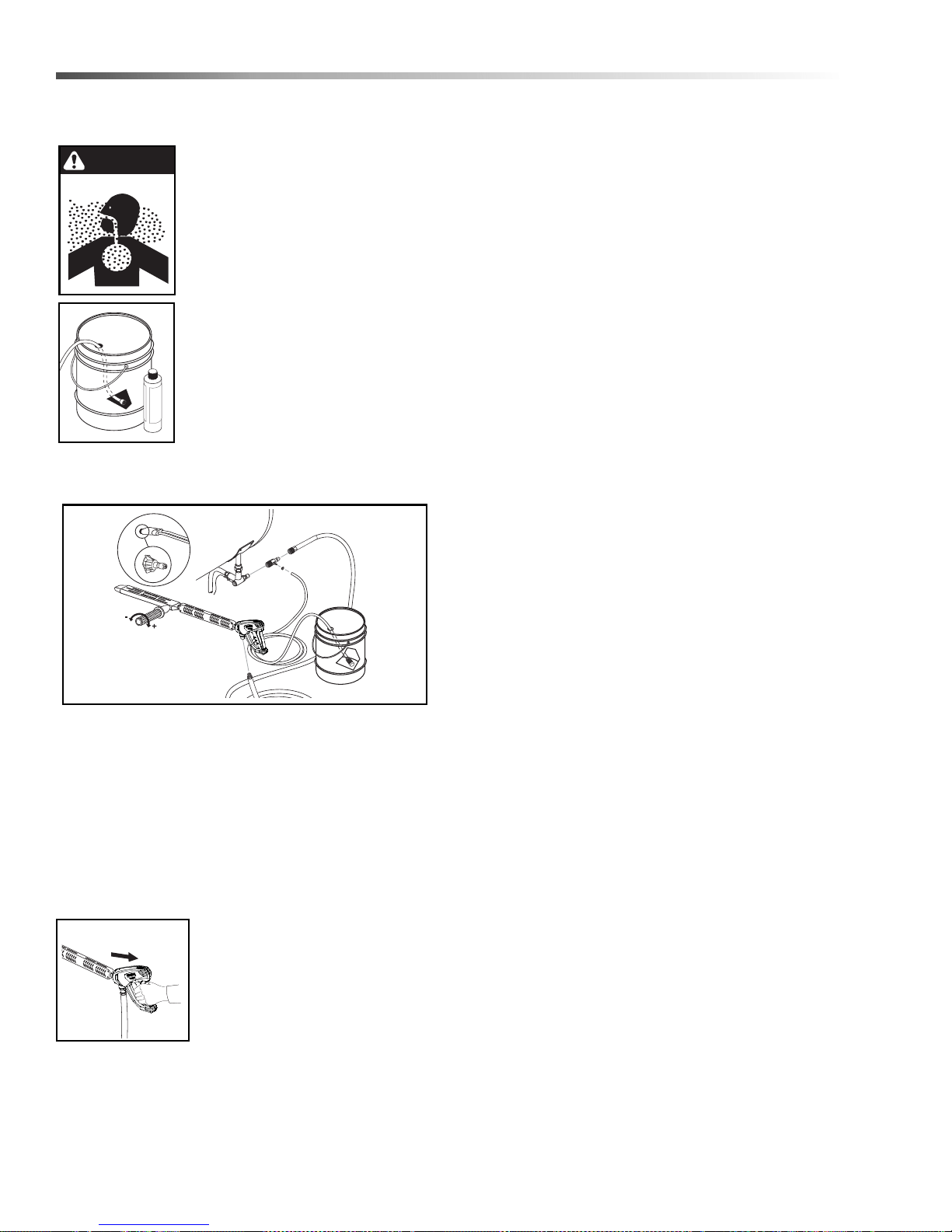
To apply detergent, place detergent pick-up tube into a container of
detergent and turn the detergent valve counterclockwise.
Landa PGDC Operator’s Manual 8.916-596.0 - P
11
Page 12
Operations
WARNING
Detergents & General Cleaning
Techniques
WARNING: Some detergents may
be harmful if inhaled or ingested,
causing severe nausea, fainting or
poisoning. The harmful elements
may cause property damage or
severe injury.
STEP 1: Use detergent designed
specifically for pressure washers.
Household detergents could
damage the pump. Prepare
detergent solution as required by the
manufacturer. Fill a container with
pressure washer detergent. Place
the filter end of detergent suction
tube into the detergent container.
STEP 2: Apply safety latch to spray gun trigger.
Secure black detergent nozzle into quick coupler.
NOTE: Detergent cannot be applied using the Yellow
nozzle.
STEP 3: Selection of high or low pressure is accompanied by turning the handle. NOTE: High pressure
nozzle must be inserted at end of wand to obtain high
pressure. To apply soap connect detergent injector to
discharge nipple and secure by pushing coupler collar
forward. Turn handle to lower pressure (water will exit
both nozzles). Place detergent pick-up tube into
detergent container. Rinse by turning handle for high
pressure.
STEP 4: With the engine running,
pull trigger to operate machine.
Liquid detergent is drawn into the
machine and mixed with water.
Apply detergent to work area. Do
not allow detergent to dry on
surface.
IMPORTANT: You must flush the detergent
injection system after each use by placing the
suction tube into a bucket of clean water, then run
the pressure washer in low pressure for 1-2
minutes.
Thermal Pump Protection
If you run your pressure washer for 3-5 minutes without
pressing the trigger on the spray gun, circulating water
in the pump can reach high temperatures. When the
water reaches this temperature, the pump protector
engages and cools the pump by discharging the warm
water onto the ground. This thermal device prevents
internal damage to the pump.
Cleaning Tips
Pre-rinse cleaning surface with fresh water. Place
detergent suction tube directly into cleaning solution
and apply to surface at low pressure (for best results,
limit your work area to sections approximately 6 feet
square and always apply detergent from bo ttom to top).
Allow detergent to remain on surface 1-3 minutes. Do
not allow detergent to dry on surface. If surface
appears to be drying, simply wet down surface with
fresh water. If needed, use brush to remove stubborn
dirt. Rinse at high pressure from top to bottom in an
even sweeping motion keeping the spray nozzle
approximately 1 foot from cleaning surface. Use overlapping strokes as you clean and rinse any surface. For
best surface cleaning action spray at a slight angle.
Recommendations:
• Before cleaning any surface, an inconspicuous
area should be cleaned to test spray pattern
and distance for maximum cleaning results.
• If painted surfaces are peeling or chipping, use
extreme caution as pressure washer may
remove the loose paint from the surface.
• Keep the spray nozzle a safe distance from the
surface you plan to clean. High pressure wash
a small area, then check the surface for
damage. If no damage is found, continue to
pressure washing.
CAUTION - Never use:
• Bleach, chlorine products and other corrosive
chemicals
• Liquids containing solvents (i.e., paint thinner,
gasoline, oils)
• Tri-sodium phosphate products
• Ammonia products
• Acid-based products
These chemicals will harm the machine and will
damage the surface being cleaned.
Rinsing
It will take a few seconds for the detergent to
clear.Appl y safety latch to spray gun. Remove black
soap nozzle from the quick coupler. Select and install
the desired high pressure nozzle. NOTE: You can also
stop detergent from flowing by simply removing
detergent siphon tube from bottle.
12
Landa PGDC Operator’s Manual 8.916-596.0 - P
Page 13
Shutting Down And
Burner
Switch
Engine
Key Switch
Clean-up
Operations
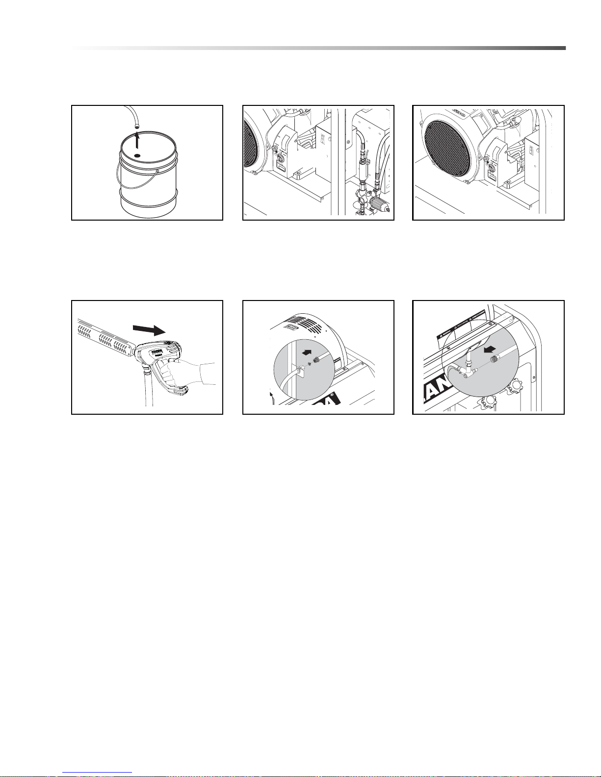
STEP 1: Remove detergent suction
tube from container and insert into
one (1) gallon of fresh water. Pull
trigger on spray gun and siphon
water for one minute.
STEP 4: Squeeze trigger on spray
gun to relieve remaining pressure.
STEP 2: T urn burner switch of f and
continue spraying, allowing the
water to cool to below 100°F.
STEP 5: Remove water supply
hose.
STEP 3: T urn engine key switch off
and turn off water.
STEP 6: Disconnect high pressure
hose from high pressure outlet.
Landa PGDC Operator’s Manual 8.916-596.0 - P
13
Page 14

Maintenance
Storage
CAUTION: Always store your pressure washer in a
location where the temperature will not fall below
32°F (0°C). The pump in this machine is susceptible
to permanent damage if frozen. FREEZE DAMAGE
IS NOT COVERED BY WARRANTY.
1. Stop the pressure washer, squeeze spray gun
trigger to release pressure.
2.
Detach water supply hose and high pressure hose.
3. Turn on the machine for a few seconds, until
remaining water exits. Turn engine off immediately.
4. Drain the gas and oil from the engine.
5. Do not allow high pressure hose to become kinked.
6. Store the machine and accessories in a room
which does not reach freezing temperatures.
CAUTION: Failure to follow the above directions
will result in damage to your pressure washer.
When pressure washer is not being operated or is
being stored for more than one month, follow these
instructions:
Engine Maintenance
During the winter months, rare atmospheric conditions
may develop which will cause an icing condition in the
carburetor . If this develops, the engine may run rough,
lose power and may stall. This temporary conditio n can
be overcome by deflecting some of the hot air from the
engine over the carburetor area. NOTE: Refer to the
engine manufacturer’s manual for service and maintenance of the engine.
1. Check to see that water pump is properly
lubricated.
2. Follow winterizing instructions to prevent freeze
damage to pump and coils.
3. Always neu tralize and flush detergent from system
after use.
4. If water is known to be high in mineral content, use
a water softener on your water system, or de-scale
as needed.
5. Do not allow acidic, caustic or abrasive fluid s to be
pumped through system.
6. Always use high grade quality cleaning products.
1. Replenish engine oil to upper level.
2. Drain gasoline from fuel tank, fuel line, fuel valve
and carburetor.
3. Pour about one teaspoon of engine oil through
spark plug hole, pull starter grip several times and
replace the plug. Then pull the starter grip slowly
until you feel increased pressure which indicates
the piston is on its compression stroke and leave it
in that position. This closes both the intake and
exhaust valves to prevent rusting of cylinder.
4. Cover pressure washer and store in a clean, dry
place that is well ventilated away from open flame
or sparks. NOTE: The use of a fuel additive, such
as STA-BIL
formulation of fuel deposits during storage. Such
additives may be added to gasoline in fuel tank of
the engine, or to gasoline in a storage container.
®
, or an equivalent, will minimize the
After Extended Storage
CAUTION: Prior to restarting, thaw out any
possible ice from pressure washer hoses, spray
gun or wand.
7. Never run pump dry for extended periods of time.
8. Use clean fuel-kerosene, No. 1 fuel oil, or diesel.
Clean or replace fuel filter every 100 hours of operation. Avoid water contaminated fuel as it will
damage the fuel pump.
9. If machine is operated with smoky or eye burning
exhaust, coils will soot up, not letting water reach
maximum operating temperature.
10. Never allow water to be sprayed on or near the
engine or burner assembly or any electrical
component.
11. Periodically delime coils as per instructions.
12. Check to see that engine is properly lubricated.
It is advisable, periodically, to visually inspect the
burner . Check air inlet to make su re it is not clogged or
blocked. Wipe off any oil spills and keep equipment
clean and dry.
The flow of combustion and ventilating air to the burner
must not be blocked or obstructed in any manner.
The area around the Landa washer should be kept
clean and free of combustible materials, gasoline and
other flammable vapors and liquids.
14
Landa PGDC Operator’s Manual 8.916-596.0 - P
Page 15

Maintenance
Unloader Valves
Unloader valves are preset and tested at the factory
before shipping. Occasional adjustment of the unloader
may be necessary to maintain correct pressure.
Winterizing Procedure
Damage due to freezing is not covered by warranty.
Adhere to the following cold weather procedures
whenever the washer must be stored or operated
outdoors under freezing conditions.
During winter months, when temperatures drop below
32°F, protecting your machine against freezing is
necessary. Store the machine in a heated room. If this
is not possible then mix a 50/50 solution of anti-freeze
and water in the float tank. T urn the engine on to siphon
the anti-freeze mixture through the machine. If
compressed air is available, an air fitting can be
screwed into the float tank by removing the float tank
strainer and fitting. Then inject the compressed air.
Water will be blown out of the machine when the trigger
on the spray gun is opened.
High Limit Hot Water Thermostat
For safety, each machine is equipped with a temperature sensitive high limit control switch. In the event that
the water should exceed its operating temperature, the
high limit control will turn the burner off until the water
cools then automatically reset itself. The thermostat
sensor is located on the discharge side of the heating
coil. The thermostat control dial is located on the
control panel.
Pumps
Use only SAE 10W-40 weight non-foaming oil. Change
oil after first 50 hours of use. Thereafter, change oil
every year or at 500 hour intervals. Oil level should be
checked through use of dipstick found on top of pump,
or the red dot visible through the oil gauge window. Oil
should be maintained at that level.
Cleaning of Coils
In alkaline water areas, lime deposits can accumulate
rapidly inside the heating coil. This growth is increased
by the extreme heat build up in the coil. The best
preventative for liming conditions is to use high quality
cleaning detergents. In areas where alkaline water is
an extreme problem, periodic use of Landa Coil
Descaler (part #8.914-296.0) will remove lime and
other deposits before coil becomes plugged.
Periodic descaling of the heating coil is recommended so please consult your local Landa Dealer
for instruction.
Removal of Soot and Heating Coil
In the heating process, fuel residue in the form of soot
deposits may develop between the heating coil pipe
and block air flow which will affect burner combustion.
When soot has been detected on visual observation,
the soot on the coil must be washed off after following
the coil removal steps (See Coil Removal).
Rupture Disk
If pressure from pump or thermal expansion should
exceed safe limits, the rupture disk will burst allowing
high pressure to be discharged thr ough hose to ground.
When disk ruptures it will need to be replaced.
Fuel
Use clean fuel oil that is not contaminated with water
and debris. Replace fuel filter and drain tank every 100
hours of operation. Use No. 1 or No. 2 Heating Oil
(ASTM D306) only . NEVER use gasoline in your burner
tank. Gasoline is more combustible than fuel oil and
could result in a serious explosion. NEVER use
crankcase or waste oil in your burner. Fuel unit
malfunction could result from contamination.
Landa PGDC Operator’s Manual 8.916-596.0 - P
15
Page 16
Maintenance
KNA Burner Gauge
SERVICE HOTLINE 1-800-833-1600
C ELZZON
L
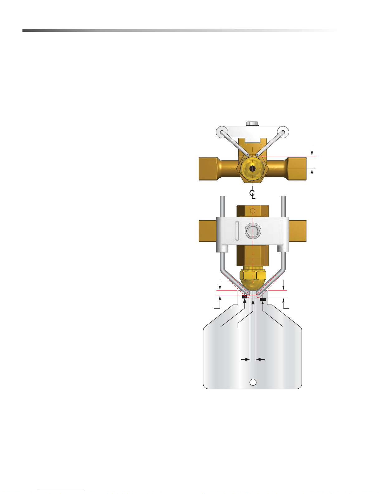
ELECTRODE POSITION
1/8 FOR AC CONE
8.922-740.0
ELECTRODE GAP
1/8 MIN 5/32 MAX
ELECTRODE POSITION
3/16 FOR DC CONE
3/16” FOR
DC CONE
1/8” FOR
AC CONE
1/4” Above
Nozzle Center
Fuel Control System
These machines utilize a fuel solenoid valve located on
the fuel pump to control the flow of fuel to the combustion chamber. This solenoid valve, which is normally
closed, is activated by a flow switch when water is
flowing through it. When an operator releases the
trigger on the spray gun, the flow of water through the
flow switch stops, turning off the current to the fuel
solenoid. The solenoid then closes, shutting off the
supply of fuel to the combustion chamber. Controlling
the flow of fuel in this way allows for an instantaneous
burn or no burn situation, thereby eliminating high and
low water temperatures, and combustion smoke
normally associated with units incorporating a spray
gun.
CAUTION: Periodic inspection is recommended to
insure that the fuel solenoid valve functions
properly. This can be done by operating the
machine and checking to see that when the trigger
on the spray gun is in the off position, the burner is
not firing.
Fuel Pressure Adjustment
Electrode Setting
Burner Nozzle
Keep the tip free of surface deposits by wiping it with a
clean, solvent-saturated cloth, being careful not to plug
or enlarge the nozzle. For maximum efficiency, replace
the nozzle each season.
Electrode
To adjust fuel pressure, turn the adjusting screw
clockwise to increase, counterclockwise to decrease.
Do not exceed 200 psi.
NOTE: When changing fuel pump, a bypass plug must
be installed in return port or fuel pump will not prime.
Periodically Check Wiring Connections. If Necessary
To Adjust Electrodes, Use Diagram.
16
Landa PGDC Operator’s Manual 8.916-596.0 - P
Page 17
Maintenance
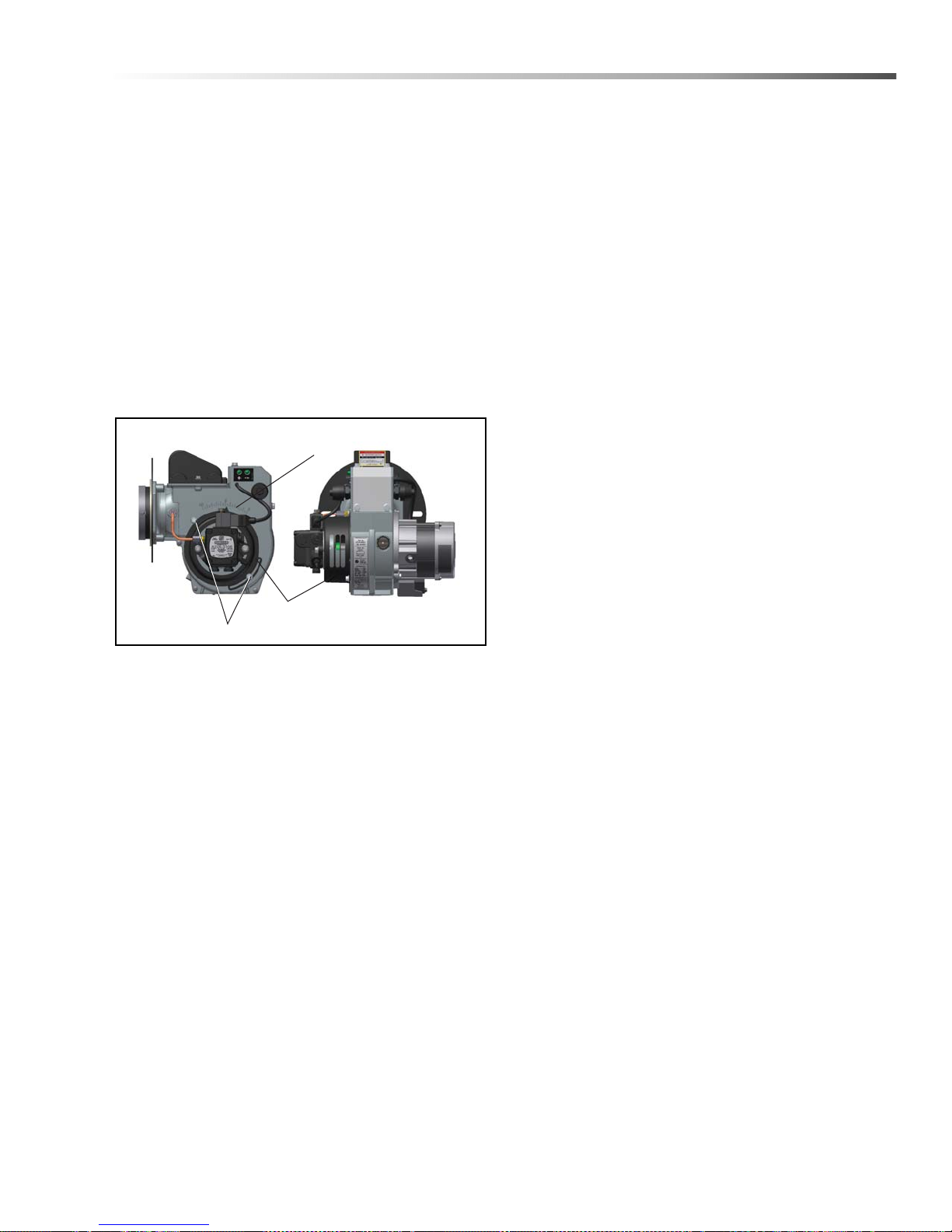
Reference Numbers
Air Band Locking Screws
Air Band
Landa Sure Fire Oil Burner
Burner Air Adjustment: The oil burner on this
machine is preset for operation at altitudes below 500
feet. If operated at higher altitudes, it may be necessary
to adjust the air band for a #1 or #2 smoke spot on the
Bacharach scale.
To adjust, start machine and turn burner ON. Loosen
two locking screws found on the air band and close air
band until black smoke appears from burner exhaust
vent. Note air band position. Next, slowly open the air
band until white smoke just starts to appear. Turn air
band halfway back to the previously noted position.
Tighten locking screws.
Burner Air Adjustment
Coil Removal
Removal of coil, because of freeze breakage or to
clean soot from it, can be done quickly and easily.
1. Disconnect hose from pump to inlet side of
the coil.
2. Carefully disconnect thermostat sensor from
electrical connection.
3. Remove all the fittings from the inlet and discharge
side of coil.
4. Remove the burner assembly from the combustion
chamber.
5. Remove the 3-3/8" bolts from each side of coil and
tank assembly (these bolts are used to fasten tank
to chassis).
6. Remove the two bolts which are underneath the
bottom wrap (to keep the coil from moving.)
7. Remove tank top wrap exposing insulation
and coil.
8. Bend back insulation tabs.
9. Carefully fold back the insulation and remove insulation retainer plates and coil.
CAUTION: If white smoke appears from burner
exhaust vent during start-up or operation,
discontinue use and readjust air bands.
NOTE: If a flue is installed, have a professional
serviceman adjust your burner for a #1 or #2 smoke
spot on the Bacharach scale.
10. Replace or repair coil and any insulation found to
be torn or broken.
11. Reinstall 1/2" pipe nipples into coil.
Coil Reinstallation
Reinstall new or cleaned coil by reversing Steps 9
through 1.
Final Note
The 12 VDC burner systems can draw as much as 18
amps! For such motors to run properly, the battery and
engine charging system must be kept in good condition, and the engine must run fast enough to
adequately charge the battery. Do not throttle down the
engine at any time while the machine is operating.
Landa PGDC Operator’s Manual 8.916-596.0 - P
17
Page 18
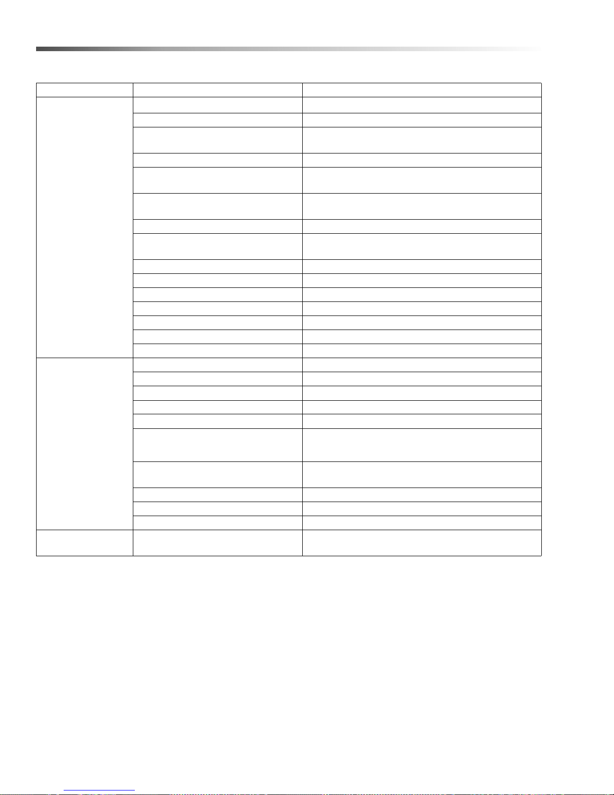
Maintenance
Troubleshooting
PROBLEM POSSIBLE CAUSE SOLUTION
Faulty pressure gauge Install new gauge.
Insufficient water supply Use larger supply hose; clean filter at water inlet.
Match nozzle number to machine and/or replace with
new nozzle.
Check plumbing system for leaks. Re-tape leaks with
teflon tape.
Adjust unloader for proper pressure. Install repair kit
when needed.
Clean inlet and
discharge valves.
Increase fuel pressure to specification and/or replace
fuel pump. Test with pressure gauge.
Test transformer for proper arc between contacts.
Replace as needed.
All wire contacts should be clean and tight. No
breaks in wire
LOW
OPERATING
PRESSURE
BURNER
WILL NOT
LIGHT
(continued on next
page)
Old, worn or incorrect spray nozzle
Belt slippage Tighten or replace; use correct belt.
Plumbing or hose leak
Faulty or mis-adjusted unloader
valve
Worn packing in pump Install new packing kit.
Fouled or dirty inlet or discharge
valves in pump
Worn inlet or discharge valves Replace with valve kit.
Obstruction in spray nozzle Remove obstruction.
Leaking pressure control valve Rebuild or replace as needed.
Slow engine RPM Set engine speed at proper specifications.
Pump sucking air Check water supply and possibility of air seepage.
Valves sticking Check and clean or replace if necessary.
Unloader valve seat faulty Check and replace if necessary.
Little or no fuel Fill tank with fuel.
Improper fuel or water in fuel Drain fuel tank and fill with proper fuel.
Clogged fuel line Clean or replace.
Plugged fuel filter Replace as needed.
Mis-adjusted burner air bands Readjust air bands for clean burn.
Little or no fuel pressure from fuel
pump
Faulty burner transformer
30 amp circuit breaker tripped Push reset button
Bridge rectifier defective Test and replace
12 VDC relay defective Test and replace
Disconnected or short in electrical
wiring
18
Landa PGDC Operator’s Manual 8.916-596.0 - P
Page 19
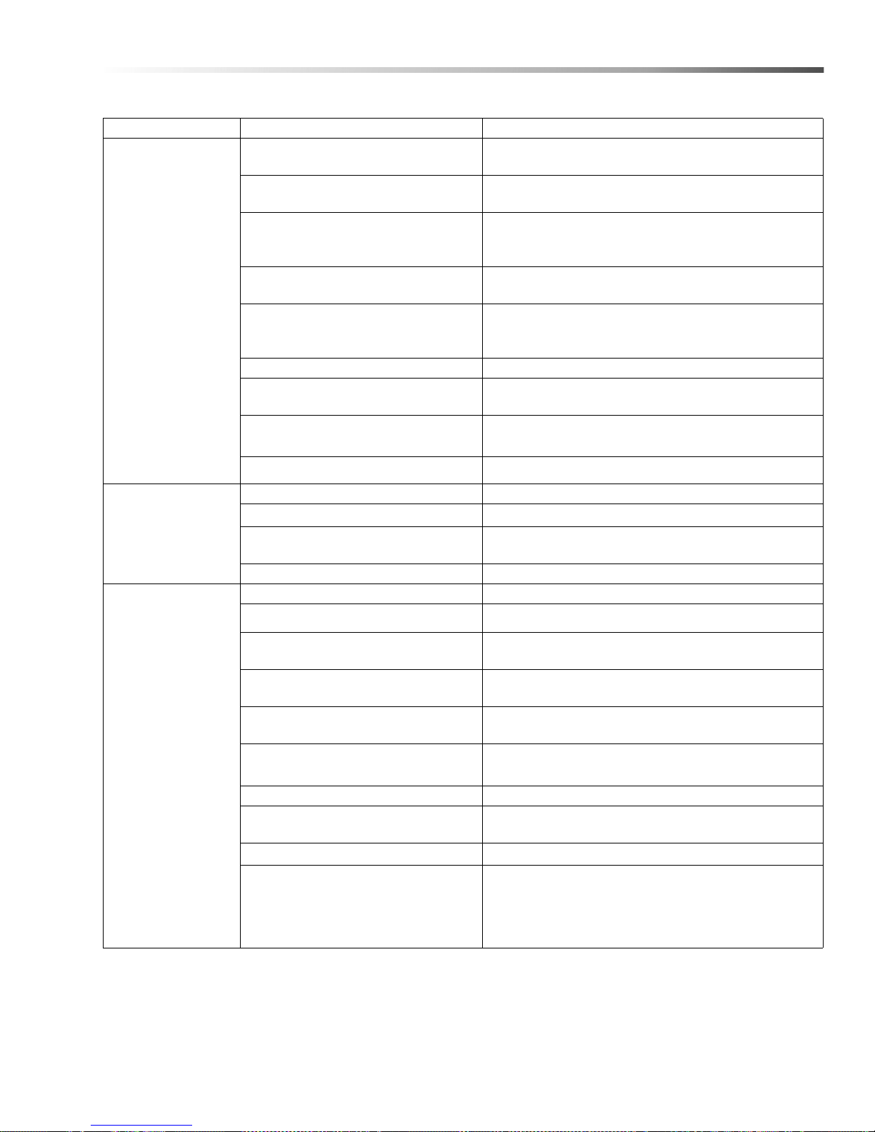
PROBLEM POSSIBLE CAUSE SOLUTION
BURNER WILL
NOT LIGHT
(continued from
previous page)
FLUCTUATING
PRESSURE
MACHINE
SMOKES
WHILE
BURNER UNIT
IS RUNNING
OR
UNIT SMOKES
AT COLD-START
ONLY WHEN
BURNER
IS OFF
Flex coupling slipping on fuel pump
shaft or burner motor shaft
On-Off switch defective
Heavy sooting on coil and burner can
cause interruption of air flow and
shorting of electrodes
Improper electrode setting
Fuel not reaching combustion
chamber
Clogged burner nozzle Clean as required.
Thermostat faulty or slow engine
speed
Flow switch malfunction Remove, test for continuity and replace as needed.
Flow solenoid malfunction Replace if needed.
Valves worn Check and replace if necessary.
Blockage in valve Check and replace if necessary.
Pump sucking air
Worn piston packing Check and replace if necessary.
Improper fuel or water in fuel Drain tank and replace contaminated fuel.
Improper air adjustment Readjust air bands on burner assembly.
Fuel pressure is low <140 psi for
burner
Plugged or dirty burner nozzle
Faulty burner nozzle spray pattern
Heavy accumulation of soot on coils
and burner assembly
Misaligned electrode setting Realign electrodes to specifications.
Obstruction in smoke stack
Low engine RPM Increase RPM to correct specs. See serial plate.
Replace if needed.
Check for electrical current reaching burner
assembly with burner switch on.
Clean as required.
Check and reset according to diagram
in Operator’s Manual.
Check fuel pump for proper flow. Check solenoid
flow switch on machines with spray gun control, for
proper on-off fuel flow control.
Increase engine RPM to increase voltage.
Check water supply and air seepage at joints in
suction line.
Adjust fuel pump pressure to specifications.
Replace nozzle. Check parts breakdown
for nozzle size
Replace nozzle. Check parts breakdown
for nozzle size.
Remove coils and burner assembly, clean thor-
oughly. Call local dealer.
Check for insulation blockage or other foreign
objects.
Maintenance
Fuel Pressure is too high for clean
burn (fuel PSI above 140 and below
200) and smokes when burner is off
Landa PGDC Operator’s Manual 8.916-596.0 - P
Reduce fuel pressure PSI/Increase air band set for
cleaner without max water heat loss
19
Page 20
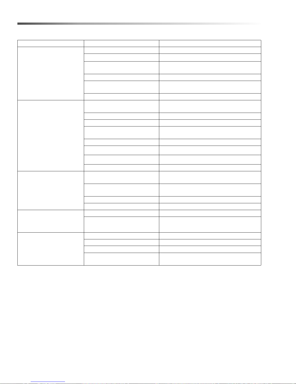
Maintenance
PROBLEM POSSIBLE CAUSE SOLUTION
LOW
WATER
TEMPERAT URE
WATER
TEMPERAT URE
TOO HOT
PUMP
NOISY
PRESENCE
OF WATER
IN OIL
WATER DRIPPING
FROM UNDER PUMP
Improper fuel or water in fuel Replace with clean and proper fuel.
Low fuel pressure Increase fuel pressure.
Weak fuel pump
Fuel filter partially clogged Replace as needed.
Soot build-up on coils not allowing
heat transfer
Improper burner nozzle See specifications pages
Incoming water to machine warm
or hot
Fuel pump pressure too high See specifications for proper fuel pressure.
Fuel pump defective Replace fuel pump.
Detergent line sucking air
Defective temperature switch Replace.
Incorrect fuel nozzle size See specifications for proper fuel nozzle.
Insufficient water supplied Check water G.P.M. to machine.
Restricted water flow Check nozzle for obstruction, proper size.
Air in suction line
Broken or weak inlet or discharge
valve springs
Excessive matter in valves Check and clean if necessary.
Worn bearings Check and replace if necessary.
Oil seal worn Check and replace if necessary.
High humidity in air Check and change oil twice as often.
Piston packing worn Check and replace if necessary.
O-Ring plunger retainer worn Check and replace if necessary.
Cracked piston Check and replace if necessary.
Pump protector
Check fuel pump pressure. Replace pump if
needed.
Clean coils.
Lower incoming water temperature.
Tighten all clamps. Check detergent lines for
holes
Check water supply and connections on
suction line.
Check and replace if necessary.
Lower water supply pressure. Do not run with
spray gun closed longer than 2 minutes.
20
Landa PGDC Operator’s Manual 8.916-596.0 - P
Page 21
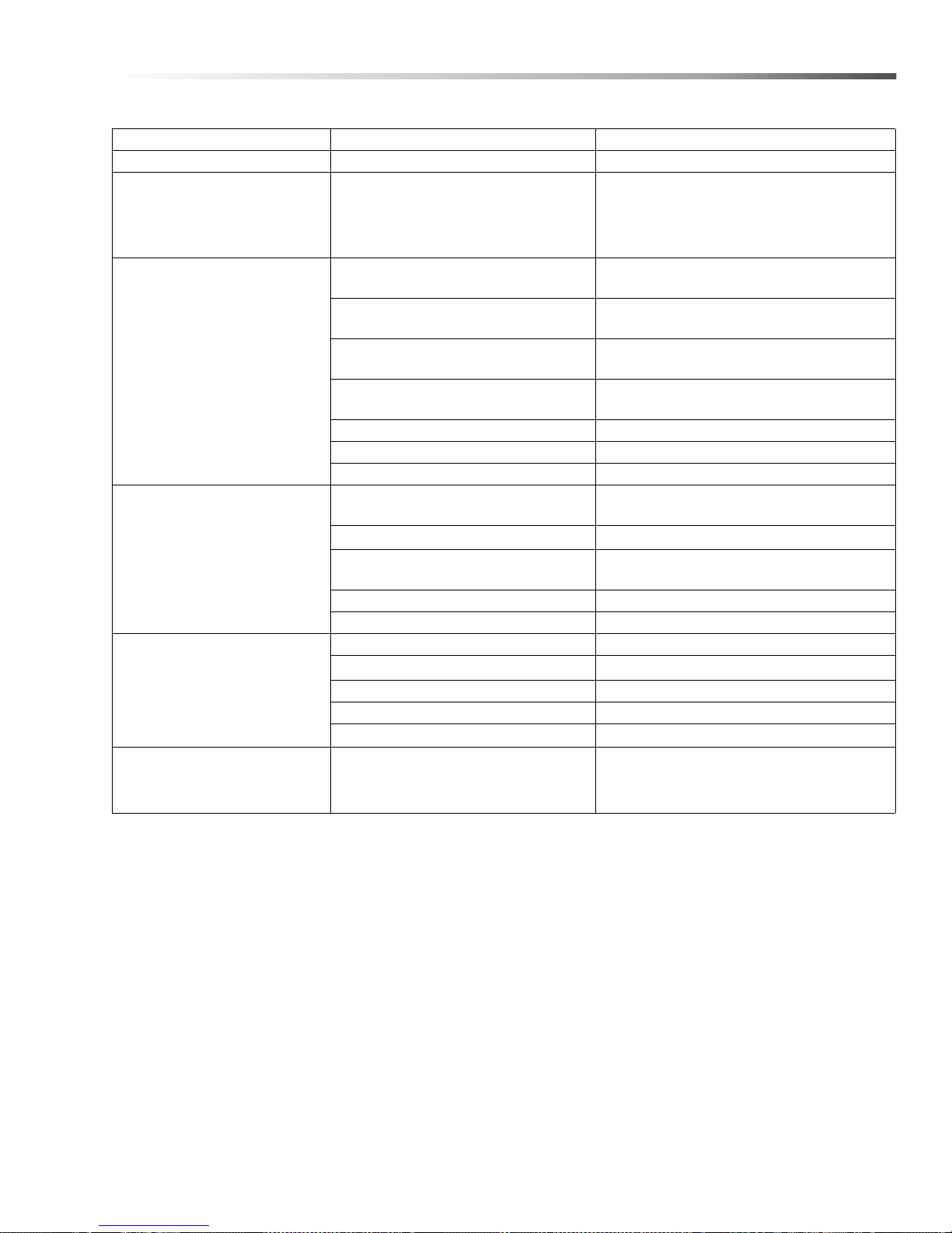
Maintenance
PROBLEM POSSIBLE CAUSE SOLUTION
OIL DRIPPING Oil seal worn Check and replace if necessary.
EXCESSIVE
VIBRATION
IN DELIVERY LINE
Irregular functioning of the valves Check and replace if necessary.
DETERGENT
NOT DRAWING
FROM SOURCE
PUMP RUNNING
NORMALLY
BUT PRESSURE
LOW ON
INSTALLATION
BURNER
MOTOR
WILL NOT RUN
Air leak
Restrictor in float tank is missing
Filter screen on detergent suction
hose plugged
Dried up detergent plugging metering
valve
High viscosity of detergent Dilute detergent to specifications.
Hole in detergent line(s) Repair hole.
Low detergent level Add detergent, if needed.
Pump sucking air
Valves sticking Check and clean or replace if necessary.
Nozzle incorrectly sized
Unloader valve seat faulty Check and replace if necessary.
Worn piston packing Check and replace if necessary.
Fuel pump seized Replace fuel pump.
Burner fan loose or misaligned Position correctly, tighten set screw.
Defective control switch Replace switch.
Loose wire Check and replace or tighten wiring.
Defective burner motor Replace motor.
Tighten all clamps. Check detergent lines
for holes.
Replace restricter . Check for proper orifice
in restrictor.
Clean or replace.
Disassemble and clean thoroughly
Check water supply and
possibility of air seepage.
Check and replace if necessary
(See serial plate for proper size).
RELIEF VALVE
LEAKS WATER
Landa PGDC Operator’s Manual 8.916-596.0 - P
Relief valve defective Replace or repair.
21
Page 22
Maintenance
Preventative Maintenance
This pressure washer was produced with the best available materials and quality craftsmanship. However, you as
the owner, have certain responsibilities for the correct care of the equipment. Attention to regular preventative
maintenance procedures will assist in preserving the performance of your equipment. Contact your Landa dealer
for maintenance. Regular preventative maintenance will add many hours to the life of your pressure washer.
Perform maintenance more often under severe conditions.
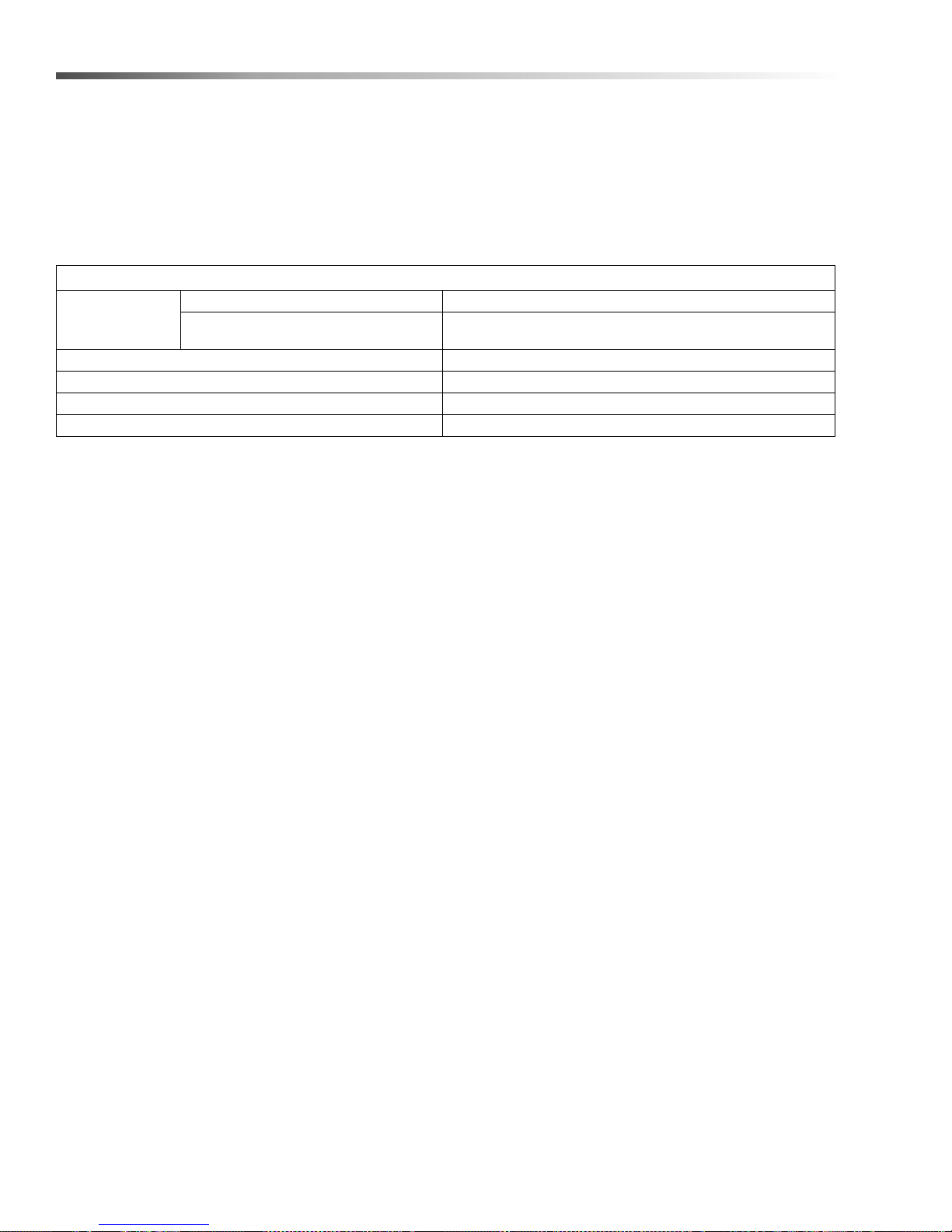
Maintenance Schedule
Pump Oil
(Non-foaming)
SAE 10W-40
Replace High Pressure Nozzle Every 6 months
Replace Quick Connects Annually
Clean Water Screen/Filter Weekly
Replace HP Hose Annually
Inspect Oil level daily
Change After first 50 hours, then every 500 hours or annually
22
Landa PGDC Operator’s Manual 8.916-596.0 - P
Page 23
Maintenance
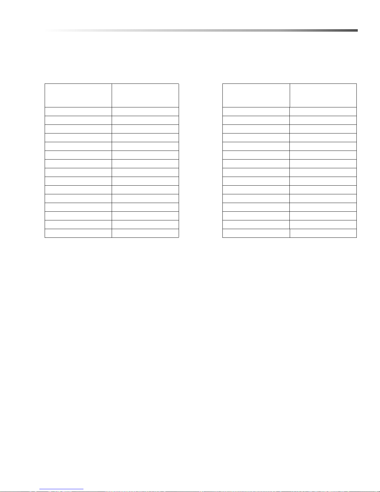
Oil Change Record
Check pump oil level before first use of your new Power Washer. Change pump oil after first 50 hours and every
year or 500 hours thereafter. Use SAE 10W-40 non-foaming oil.
D at e O i l C ha ng e d
Month/Day/Year
Estimated Operating
Hours Since Last Oil
Change
D at e O i l C ha ng e d
Month/Day/Year
Estimated Operating
Hours Since Last Oil
Change
Landa PGDC Operator’s Manual 8.916-596.0 - P
23
Page 24

Notes
24
Landa PGDC Operator’s Manual 8.916-596.0 - P
Page 25

Parts
Parts
LANDA PGDC
PGDC4 - 3500
1.110-049.0
PGDC5 - 3500
1.110-050.0
PGDC5 - 3500
1.110-051.0
PGDC8 - 3000
1.110-072.0
Landa PGDC Operator’s Manual 8.916-596.0 - P
25
Page 26
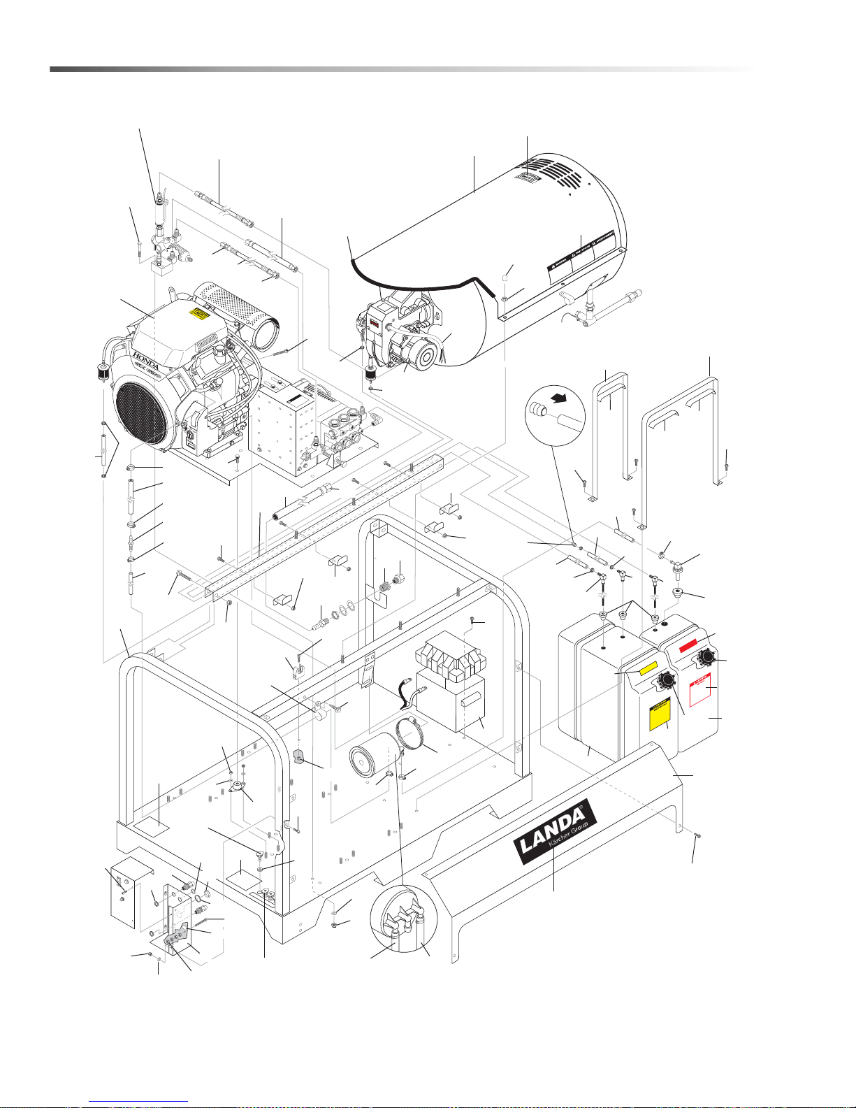
Landa PGDC
91
GAS
8
.916
-27
4.0
DIESEL
8.932
-960.0
EXP
OS
E
D
PULLEY
S
AN
D
B
E
L
T
S
CAN C
AUSE I
NJU
R
Y
P
R
EC
A
U
C
I
O
N
/
A
V
ER
TIS
SEME
N
T
W
ARNIN
G
To
Tank
66
84
9
58
65
81
33
5
78
61
4
59
54
60
55
72
36
37
42
1
2
35
21
20
19
24
76
74
12
8
50
51
43
93
44
73
67, 68,
69, 70
82
32
29
26
86
28
31
27
93
16
14
11
93
6
7
53
23
76
15
10
24
4
4
3
7
34
52
28
18
47
17
79
25
77
85
62
39
57
75
38
93
80
36
46
22
48
49
13
71
56, 63
45
85
41
30
28
88
87
64
83
89
88
87
91
92
90
87
91
85
87
45
Landa PGDC Operator’s Manual 8.916-596.0 - P
26
Page 27
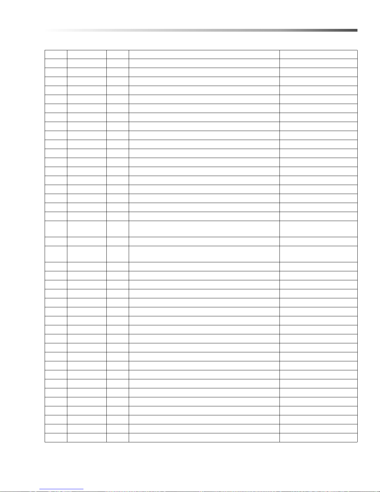
Landa PGDC
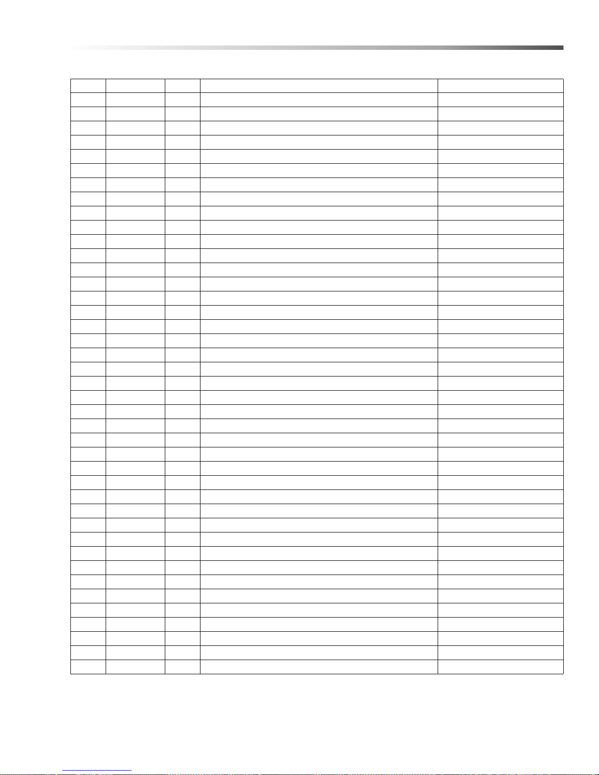
REF PART NO. QTY DESCRIPTION NOTES
1 8.706-604.0 1 TANK, FUEL, 5 GAL., RED 1.110-050.0, 1.110-051.0
2 8.706-603.0 1 TANK, FUEL, 10 GAL. POLY YELLOW
3 8.921-148.0 2 STRAP, FUEL TANK SINGLE 1.110-049.0
- - 1 STRAP, FUEL TANK SINGLE - 1.110-050.0, 1.110-051.0
4 9.802-193.0 2 GASKET, NEOPRENE 7" 1.110-049.0
- - 3 GASKET, NEOPRENE 7" 1.11 0-050.0, 1.110-051.0
5 9.802-053.0 2 BUSHING, RUBBER, NITRILE 1.110-049.0
- - 3 BUSHING, RUBBER, NITRILE 1.110-050.0, 1.110-051.0
6 9.802-054.0 1 ELBOW, FUEL TANK, ZINC
7 8.706-496.0 1 DIPTUBE ASSY , PLASTIC, 17.5" 1.110-049.0
- - 2 DIPTUBE ASSY, PLASTIC, 17.5" 1.110-050.0, 1.110-051.0
8 8.912-192.0 1 TOP WRAP, STAINLESS STEEL
9 9.802-071.0 33" TRIM, 750 B2 X 1/16 BLACK
10 9.800-002.0 1 LABEL, USE ONLY KEROSENE
11 9.800-006.0 1 LABEL, WARNING, HOT/CALIENTE W/ARROWS
12 6.390-126.0 3 HOSE CLAMP 1.110-049.0
- - 5 HOSE CLAMP 1.110-050.0, 1.110-051.0
13 8.706-727.0 1 BUSHING, 5/16", SNAP LOK
14 8.918-426.0 1 HOSE, 3/8" X 32", 2 WIRE PRESSURE LO
- 8.918-227.0 1 HOSE, 1/2" X 36", 2 WIRE, PRESSURE LO 1.110-072.0
15 8.918-425.0 1 HOSE, 3/8" X 29", 2 WIRE, PRESSURE LO
- 8.918-225.0 1 HOSE, 1/2" X 28", 2 WIRE, PRESSURE LO 1.110-072.0
16 9.802-781.0 6 NUT, 3/8" WHIZ
17 8.718-980.0 23 WASHER, 5/16" FLAT, SAE
18 9.802-776.0 23 NUT, 5/16" ESNA, NC
19 9.802-261.0 39" HOSE, 3/4"
20 9.802-728.0 2 THREADED BOLT 3/8" X 2"
21 9.802-779.0 2 NUT, 3/8"
22 9.802-807.0 2 WASHER, FLAT, 3/8"
23 9.802-259.0 24" HOSE, 1/2" PUSH-ON
24 9.802-151.0 2 SWIVEL, 1/2" JIC FEM PUSH-ON
25 8.707-020.0 1 1/2" MPT X 3/4" BARB
26 8.900-839.0 1 LABEL, PGDC SKID WARNING
27 9.802-152.0 1 SWIVEL, 3/4" SAE FEM, PUSH-ON
28 9.802-767.0 13 SCREW, 3/8" X 3/4" HH, NC, WHIZ
29 8.718-674.0 2 BOLT, 3/8-16 X 2-1/4", GR8.2 SERATED FLANGE B
30 8.752-918.0 1 CLAMP, HOSE #64SS
31 9.802-781.0 2 NUT, 3/8" FLANGE WHIZ LOC NC
32 8.706-600.0 1 BATTERY, M-100, LARGE
33 8.916-471.0 1 ASSY, POWER PLATFORM PGDC5-3500
34 8.932-992.0 9 MOUNT, RUBBER VIBRATION. 3/8" 70 DURO
1.110-049.0, 1.110-050.0,
1.110-051.0
1.110-049.0, 1.110-050.0,
1.110-051.0
27Landa PGDC Operator’s Manual 8.916-596.0 - P
Page 28
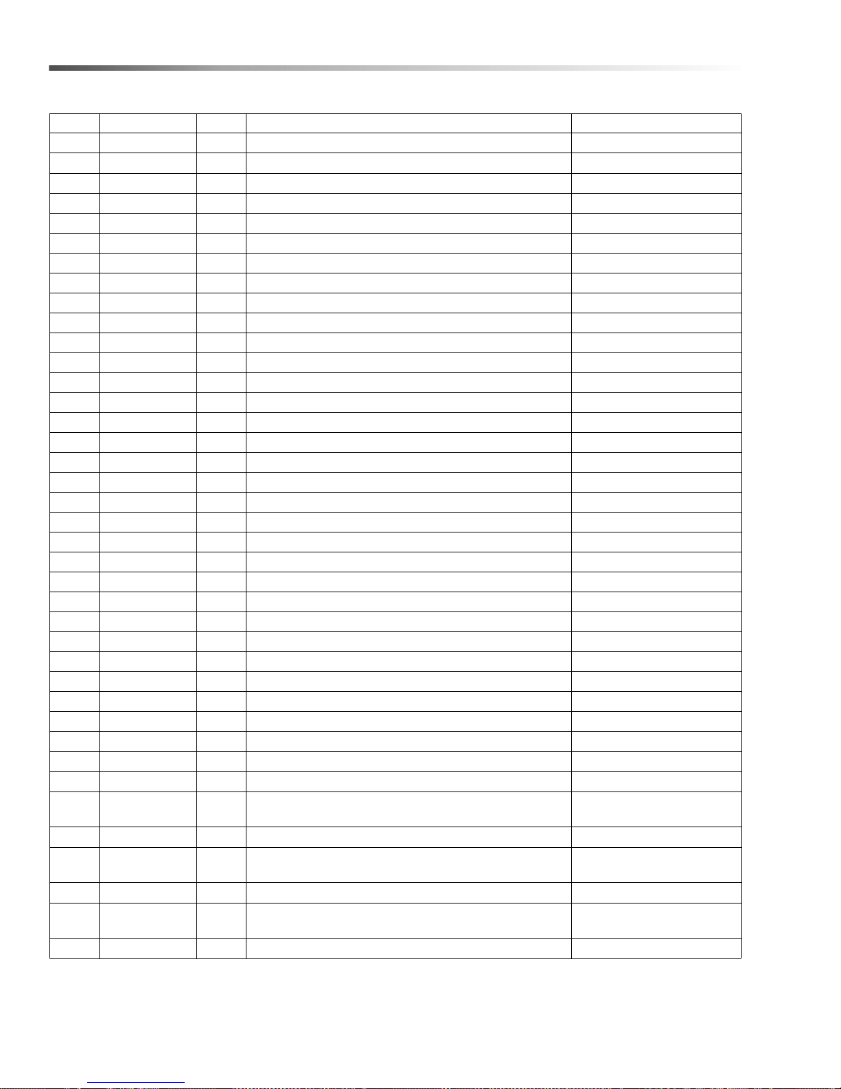
Landa PGDC
REF PART NO. QTY DESCRIPTION NOTES
35 8.920-485.0 1 WLMT, SKID, PGDC
36 9.802-089.0 1 CAP , TANK
- - 2 CAP , TANK 1.1 10-05 0.0, 1.110-051.0
37 9.800-001.0 1 LABEL, THIS T ANK FOR GAS ONL Y
38 8.920-295.0 1 SUPPORT, COIL, SKID
39 8.707-000.0 1 CONNECTOR, 1/2" ANCHOR
40 9.802-781.0 8 NUT, 3/8 FLANGE WHIZ NOT SHOWN
41 9.802-797.0 1 SCREW, #10 X 1/2" HEX HEAD SS
42 9.802-064.0 4 GROMMET, RUBBER NOZZLE HOLDER
43 8.932-960.0 1 LABEL, DIESEL, BLACK ON YELLOW
44 8.916-274.0 1 LABEL, GAS, WHITE ON RED
45 8.920-352.0 4 RETAINER, FUEL LINE
46 8.900-266.0 1 LABEL, NOZZLE
47 9.802-753.0 2 SCREW, 1/4" X 3/4"
48 9.800-975.0 1 LABEL, LANDA LOGO 4.75 X 21"
49 9.803-277.0 4 SCREW, 5/16 X 1/2 WHIZ LOC
50 8.916-443.0 1 WLMT , BACK ELECTRICAL, PGDC
51 9.802-514.0 2 STRAIN RELIEF, LT., STR., 1/2 NPT .23-45D
52 9.802-525.0 2 LOCKNUT, 1/2" 8463
53 8.916-619.0 1 PANEL, PGDC
54 9.802-428.0 30" CORD, SERVICE SJOWA 12/3
55 9.802-765.0 4 SCREW, 1/4" X 1/2"
56 8.932-968.0 1 LABEL, INTENDED FOR OUTDOOR, USE, USA
57 9.802-146.0 1 SWIVEL, 1/2" MP X 3/4" GHF
58 9.800-040.0 1 LABEL, GROUND SYMBOL
59 9.802-695.0 4 NUT, 10/32" KEPS
60 9.802-762.0 1 SCREW, 10/32" X 1-1/4" RH, SL, BLK
61 9.802-802.0 4 WASHER, 1/4", FLAT, SAE
62 8.718-781.0 1 SCREW, 40MM, PAN HD
63 9.800-034.0 1 LABEL, CLEAR LEXAN, 4.3" X 5.5"
64 8.751-215.0 1 GROMMET, REMOTE VENT
65 8.709-089.0 1 CLAMP, "WIRE/TUBE .6250"
66 8.706-735.0 1 BUSHING, 1-1/4" SNAP
67 8.712-353.0 1 NOZZLE, SAQCMEG 0005, RED
- 8.712-378.0 1 NOZZLE, SAQC MEG, 0009 1.110-072.0
68 8.712-354.0 1 NOZZLE, SAQCMEG 1505, YELLOW
- 8.712-379.0 1 NOZZLE, SAQCMEG, 1509 1.110-072.0
69 8.712-355.0 1 NOZZLE, SAQCMEG 2505, GREEN
- 8.712-380.0 1 NOZZLE SAQC MEG, 2509 1.110-072.0
1.1 10-049.0, 1.110-050.0,
1.1 10-049.0, 1.110-050.0,
1.1 10-049.0, 1.110-050.0,
1.110-049.0
1.110-051.0
1.110-051.0
1.110-051.0
28
Landa PGDC Operator’s Manual 8.916-596.0 - P
Page 29
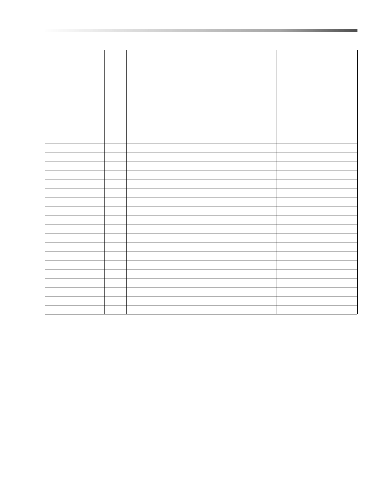
Landa PGDC
REF PART NO. QTY DESCRIPTION NOTES
70 8.712-356.0 1 NOZZLE, SAQCMEG 4005, WHITE
- 8.712-381.0 1 NOZZLE, SAQC MEG, 4009 1.110-072.0
71 8.706-744.0 1 PLUG, PLASTIC, 1"
72 - 1 BURNER ASSY
73 9.802-254.0 21" HOSE 1/4"
74 8.751-059.0 1 VENT, REMOTE ASSY
75 8.916-479.0 1 ASSY, UNLOADER, PGHW
- 8.925-188.0 1 ASSY, UNLOADER, PGDC, 8-30 1.110-072.0
76 9.802-771.0 5 SCREW, 10/32 X 3/4
77 9.802-203.0 1 CLAMP, 1/2" RO-CLIP
78 8.921-147.0 1 STRAP, FUEL TANK, DOUBLE 16HP, 20HP MODELS
79 8.940-051.0 1 LABEL, LANDA, DIESEL OP INST
80 9.800-708.0 2 SCREW , 5/16"-18" X 3/4"
81 9.802-254.0 74" HOSE 1/4"
82 9.802-773.0 3 NUT, 1/4", ESNA, NC
83 9.802-254.0 24" HOSE 1/4"
84 8.754-911.0 1 CHECK VALVE, 1 WAY, 1/4" BARB
85 9.802-695.0 5 NUT, 10/32 KEP
86 8.750-435.0 6 CAP, BLACK VINYL
87 8.753-066.0 4 CLAMP, 1 EAR, #7
88 9.802-254.0 13" HOSE, 1/4"
89 9.802-254.0 54" HOSE, 1/4"
90 8.753-270.0 1 REDUCER CONNECTOR 3/8" X 1/4"
91 8.753-065.0 2 CLAMP, 1 EAR, #10
92 8.711-785.0 6" HOSE, 3/8" PUSH-ON
93 8.709-069.0 4 CLAMP, SCREW, 5/16"W, 1/4-5/8" D, SS
1.110-049.0, 1.110-050.0,
1.110-051.0
SEE SPECIFICATIONS
PAGE
1.110-049.0, 1.110-050.0,
1.110-051.0
29Landa PGDC Operator’s Manual 8.916-596.0 - P
Page 30
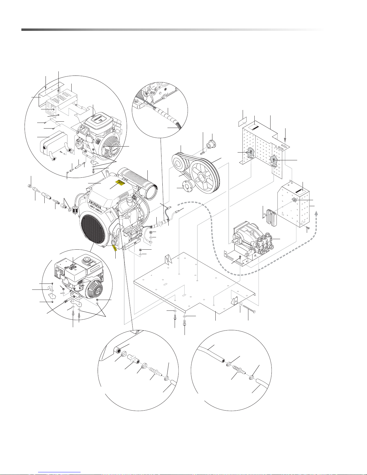
E
XPOSED P
U
LLEYS
AN
D
B
E
L
T
S
CAN C
AUSE INJ
U
R
Y
P
R
E
C
A
U
CI
O
N
/
A
V
ER
TISS
E
ME
N
T
W
ARNIN
G
E
X
PO
S
ED P
U
LLEYS
A
N
D
B
ELT
S
C
AN
C
A
USE
I
N
J
U
R
Y
P
R
E
C
A
UCI
O
N
/
A
V
ER
T
I
SS
E
MEN
T
W
ARNING
R
OUTING
CHA
U
D!
4
14
17
1
3
18
13
26
24
34
36
32
28
35
37
20
29
31
23
38
33
22
47
46
54
56
52
48
55
57
49
41
59
50
51
43
53
42
41
8
39. 40,
44, 30
25
16, 21, 12, 11
23
17
18
43
57
56
15
15
15
24
15
15
18
34
42
43
43
6
10
45
7
9
16
HP
Models
13
HP
Models
5
2
19
58
23
23
60
27
27
60
65
66
65
Vanguard
Purge Line
Connection
From Carbon
Canister
63
62
62
64
65
Engine Purge
Port
From Carbon
Canister
Honda
Power Platform
30
Landa PGDC Operator’s Manual 8.916-596.0 - P
Page 31
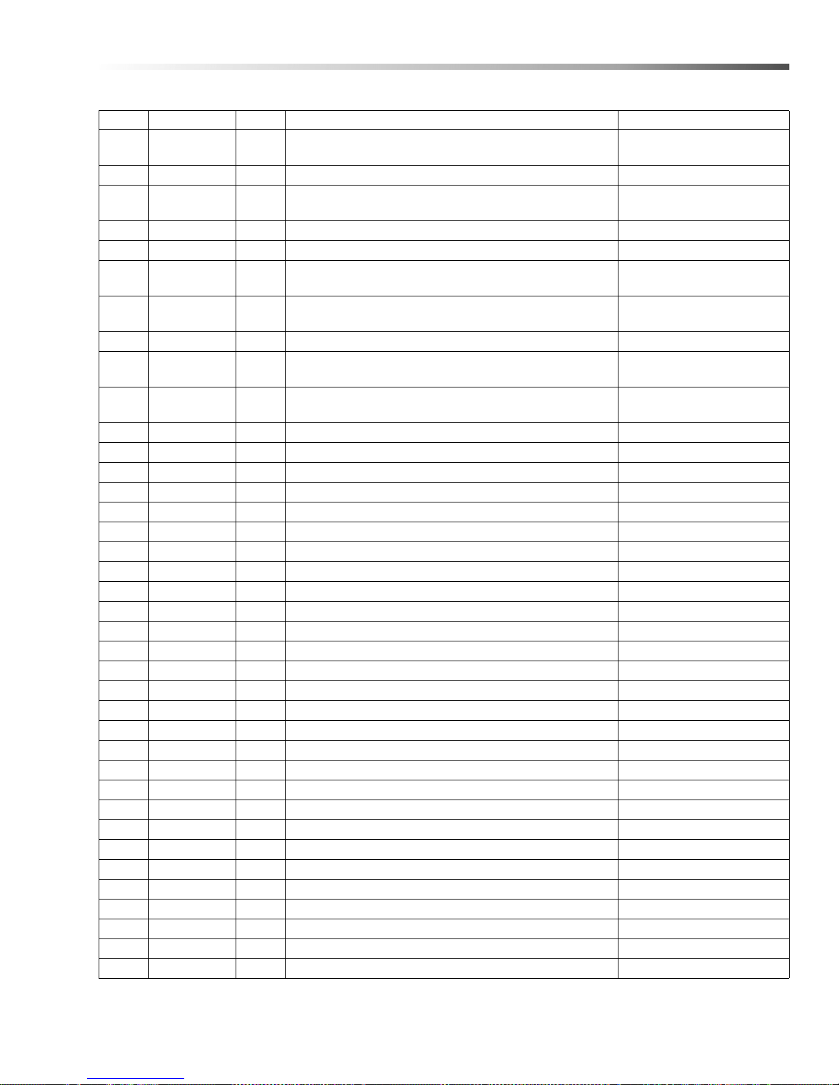
Power Platform
REF PART NO. QTY DESCRIPTION NOTES
1--ENGINE
2 9.802-695.0 1 NUT, 10/32" KEPS 1.110-049.0
3--PUMP
4 8.916-442.0 1 WLMT, PLATFORM PGDC
5 9.802-764.0 - SCREW, 10/32 X 3/4 HEX, WASH SL MACH/BLK 1.110-049.0
6 - - PUMP PULLEY
7 - - ENGINE PULLEY
8 8.709-089.0 1 CLIP, .25ID RND 1.110-049.0
9 - - PUMP BUSHING
10 - - ENGINE BUSHING
11 9.802-125.0 1 PLUG, 1/4" JIC 1.110-049.0
12 9.802-153.0 1 SWIVEL, 1/4" JIC FEM, PUSH-ON 1.110-049.0
13 9.803-845.0 1 BOLT, 1/2" X 5" NC HH TAP ALL THREAD
14 9.802-800.0 1 WASHER, 1/2" FLAT
15 9.802-767.0 11 SCREW, 3/8" X 3/4" HH, NC WHIZ
16 9.802-154.0 1 PLUG, PUSH-ON, OIL DRAIN, HONDA 1.110-049.0
17 9.802-779.0 2 NUT, 3/8"
18 9.802-807.0 8 WASHER, FLAT 3/8"
19 9.802-959.0 1 KEY, 0.247 SQR X 2.125"
20 8.912-457.0 1 WLMT, BELT GUARD, GAS PUMP 1.110-050.0, 1.110-051.0
- 8.922-994.0 1 WLMT, BELT GUARD, 13 HP, 1.110-049.0
21 9.802-254.0 7" HOSE, 1/4" 1.110-049.0
22 8.916-610.0 1 GUARD, BELT, LEFT
23 9.800-006.0 2 LABEL, WARNING, HOT/CALIENTE W/ARROWS
24 8.932-965.0 2 LABEL, WARNING, EXPOSED PULLEYS
25 9.802-775.0 3 NUT, 1/4" FLANGE, ZN 1.110-050.0
26 8.913-902.0 1 KEY, RING LANDA
27 9.802-445.0 8" WRAP, SPIRAL
28 8.716-491.0 1 CABLE, BATTERY, 61" EYE TO POST, RED
29 8.716-492.0 1 CABLE, BATTERY, 61" EYE TO POST BLACK
30 9.802-761.0 4 SCREW, M6 X 20MM BH SOC BLACK 1.110-051.0
31 9.802-259.0 7 HOSE, 1/2" PUSH-ON
32 9.802-151.0 1 SWIVEL, 1/2" JIC FEM, PUSH-ON
33 9.802-126.0 1 PLUG, 1/2" JIC FLARE 639F-8"
34 9.802-728.0 2 THREADED BOLT 3/8" X 2"
35 9.802-771.0 2 SCREW, 10/32" X 3/4" BH SOC CS
36 9.802-695.0 2 NUT, 10/32" KEPS
37 8.750-737.0 1 ADAPTER, HONDA , M20-1.5 X 3/8"
SEE SPECIFICATIONS
PAGE
SEE SPECIFICATIONS
PAGE
SEE SPECIFICATIONS
PAGE
SEE SPECIFICATIONS
PAGE
SEE SPECIFICATIONS
PAGE
SEE SPECIFICATIONS
PAGE
31Landa PGDC Operator’s Manual 8.916-596.0 - P
Page 32
Power Platform
REF PART NO. QTY DESCRIPTION NOTES
38 8.707-019.0 1 PUSH-ON, 1/2" BARB X 3/8" MPT
39 8.750-497.0 1 MUFFLER, HONDA, RIGHT
40 8.739-597.0 2 BOLT, FLANGE, 8 X 20MM, GX610/620
41 8.725-319.0 2 NUT, 7.16-14 NYL, INS LN ZC
42 8.725-320.0 2 BOLT, 7/16-14 X 2 HEX TAP GRD5 ZC
43 9.802-809.0 4 WASHER, 1/2" FLAT, SAE
44 9.803-008.0 1 SHIELD, HEAT, MUFFLER GUARD
45 8.715-697.0 2 BELT, BX36
46 8.707-019.0 1 PUSH-ON 1/2" BARB X 3/8" MPT 1.110-050.0
47 9.802-259.0 7" HOSE, 1/2" PUSH-ON 1.110-050.0
48 9.802-151.0 1 SWIVEL, 1/2" JIC FEM, PUSH-ON 1.110-050.0
49 9.802-126.0 1 PLUG, 1/2" JIC FLARE, 639F-8" 1.110-050.0
50 9.802-716.0 4 BOLT, 5/16" X 2" NC HH 1.110-050.0
51 9.802-776.0 4 NUT, 5/16" ESNA, NC 1.110-050.0
52 8.718-980.0 4 WASHER, 5/16" FLAT SAE 1.11 0-050.0
53 9.802-672.0 1 MUFFLER, EXHAUST, BRIGGS 1.110-050.0
54 9.802-867.0 1 GUARD, MUFFLER, 16 HP VANGUARD 1.110-050.0
55 9.802-868.0 2 BRACE, VANGUARD, MUFFLER BRACKET 1.110-050.0
56 9.802-830.0 4 SCREW, HEX 1/4"-20 X 1/2"T/F TCS 1.110-050.0
57 9.802-754.0 5 SCREW, 1/4" X 1/2" HH, NC, WHIZ LOC 1.110-050.0
58 9.802-794.0 2 NUT, CAGE, 1/4" X 12 GA 1.110-050.0
59 9.803-011.0 1 SHIELD, HEAT, VANGUARD 1.110-050.0
60 8.716-011.0 48" CONDUIT, FLEXO
62 8.753-065.0 2 #10 CLAMP HONDA
63 8.711-785.0 6" HOSE, 3/8" PUSH-ON
64 8.753-270.0 1 REDUCER, CONNECTOR 3/8" X 1/4"
65 8.753-065.0 1 #7 CLAMP HONDA
- - 2 #7 CLAMP VANGUARD
66 8.753-269.0 1 REDUCER, CONNECTOR 1/4" X 3/16"
32
Landa PGDC Operator’s Manual 8.916-596.0 - P
Page 33
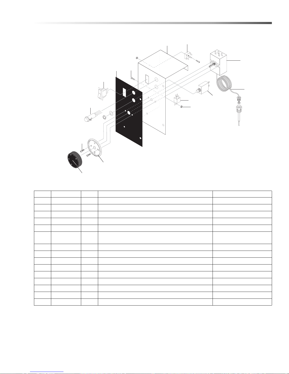
Control Box
1
2
3
5
13
4
10
11
12
6
7
8
9
14
REF PART NO. QTY DESCRIPTION NOTES
1 8.916-458.0 1 CONTROL, FRONT, PGDC
2 8.916-612.0 1 LABEL, ELECTRICAL, PGDC
3 9.802-453.0 1 SWITCH, CURVETTE
4 9.802-485.0 1 BREAKER, CIRCUIT, 25 AMP
5 9.802-456.0 1 LIGHT, INDICATOR, GREEN 12V
6 9.802-470.0 1 RELAY, 12V
(1.110-049.0 HONDA,
1.110-050.0 VAN)
- 9.802-471.0 1 24V RELAY (1.110-051.0 HONDA)
7 9.802-695.0 1 NUT, 10/32" KEPS
8 9.802-771.0 1 SCREW, 10/32 X 3/4
9 9.802-530.0 1 RECTIFIER, BRIDGE 12V DC, 30 AMP
10 8.750-095.0 1 THERMOSTAT, 120C/240F
11 8.750-097.0 1 KNOB,THERMOSTAT, 120C/240F
12 8.712-190.0 1 BEZEL,THERMOSTAT
13 8.718-779.0 2 SCREW, 4 MM X 6 MM
14 9.802-447.0 48" CONDUIT, SPLIT
33Landa PGDC Operator’s Manual 8.916-596.0 - P
Page 34
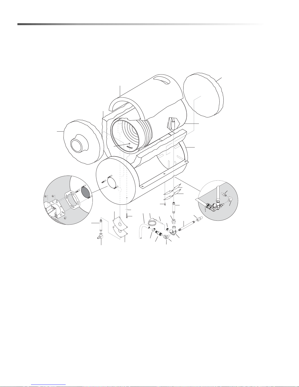
Coil
1
2
5
6
27
3
4
7
21
20
8
17
24
23
18
9
13
22
14
11
12
15
19
16
7
12
10
25
26
TR Trailer
28
29
34
Landa PGDC Operator’s Manual 8.916-596.0 - P
Page 35

REF PART NO. QTY DESCRIPTION NOTES
1 9.802-014.0 2 NIPPLE, 1/2" X 3" GALV. SCH 80
2 8.706-141.0 1 COUPLING, 1/2"
3 9.802-170.0 1 NIPPLE, 3/8" PLUG STEEL/ZINC FEMALE
4 9.802-883.0 1 INSULATION, FRONT HEAD, NO HOLE
5 9.802-894.0 1 INSULATION, BURNER HEAD, W/HOLE
6 9.802-896.0 1 INSULATION, BLANKET, NO FOIL 24" X 57"
7 8.933-009.0 2 GASKET, BURNER PLATE
8 9.802-902.0 1 INSUL/BLANKET, DIE CUT 28" X 24" X 1"
9 9.802-781.0 2 NUT, 3/8" FLANGE WHIZ LOC, NC
10 9.802-807.0 2 WASHER, FLAT 3/8"
11 8.916-486.0 1 WLMT, BOTTOM WRAP
12 9.803-132.0 2 INSULATION RETAINER PLATE
13 9.802-797.0 8 SCREW, SS #10 X 1/2 HEX HEAD TEK
14 8.912-239.0 1
15 9.149-003.0 1 MANIFOLD, COIL OUTLET
16 9.802-043.0 1 ELBOW, 1/2 JIC X 1/2 FEM 90°
17 8.707-381.0 1 RUPTURE DISC ASSY, 8500#
18 9.802-727.0 2 BOLT, 3/8" X 1-3/4" TAP
19 9.802-015.0 1 NIPPLE, 1/2" X 4" GALV. SCH 80
20 9.803-559.0 1 CLAMP,SCREW,9/16"W, 1-1/4"OD, SS
21 9.802-024.0 1 ELBOW, 3/8" MPT x 1/2" FPT STREET, STEE
22 9.802-260.0 26" HOSE, 1/2" PUSH-ON
23 9.196-012.0 1 SCREW, 10-24 X 1/4
24 8.750-097.0 1 THERMOSTAT 240° F
25 9.802-447.0 48" CONDUIT, SPLIT
26 8.706-207.0 1 ELBOW, 3/8" STREET 90°, STEEL
27 8.725-553.0 1 NIPPLE, PIPE 3/8” X 8" SCH 80
28 9.802-171.0 1 COUPLER, 3/8" PLUG, MALE STEEL/ZINC
29 8.706-248.0 1 PLUG, 3/8" ALLEN COUNTER SUNK
COIL, LANDA DURA, SCH 80 W/ALUMINIZED
STEEL WRAP
Coil
35Landa PGDC Operator’s Manual 8.916-596.0 - P
Page 36
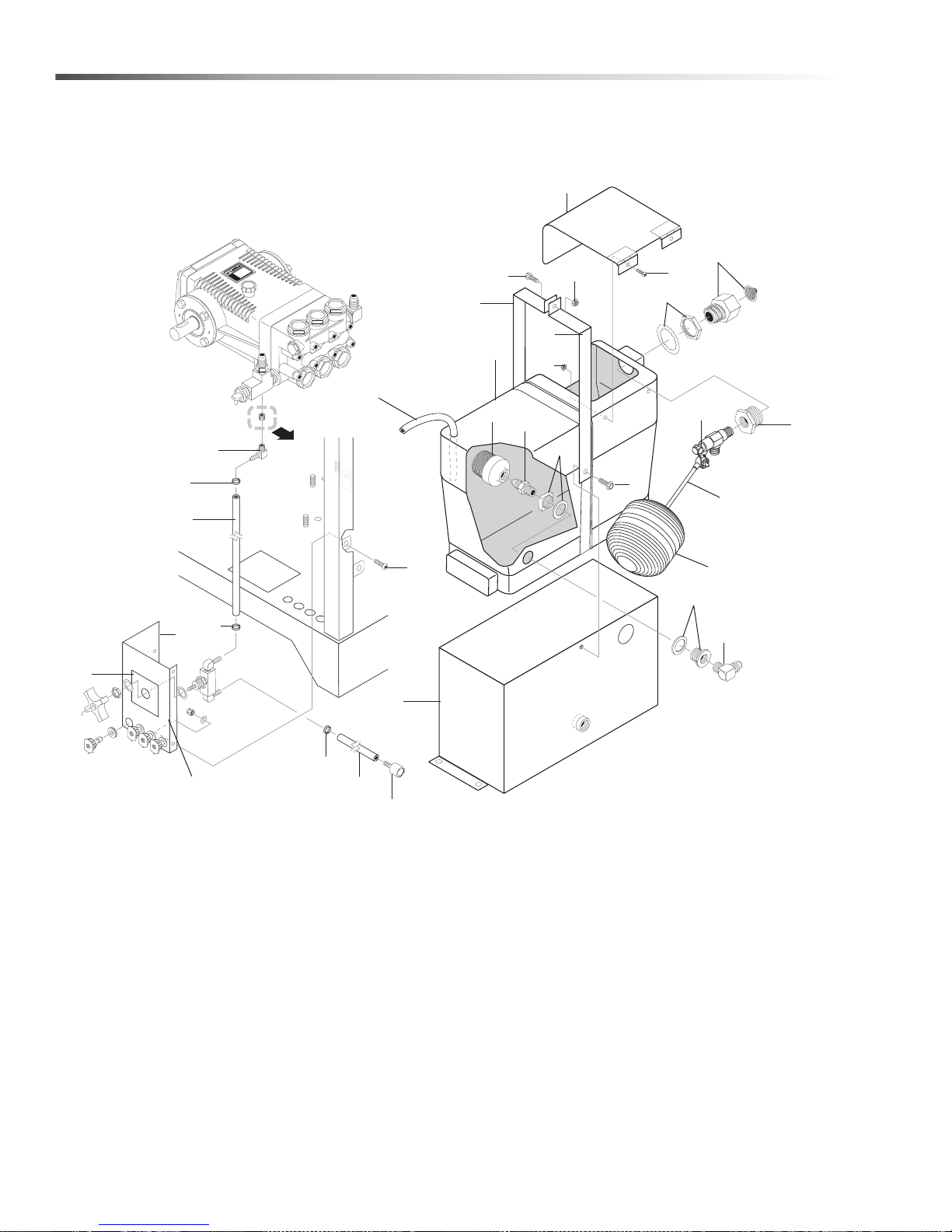
Option, Float Tank
11
12
1
2
7
4
3
5
6
10
9
13
8
14
16
15
17
18
16
8
5
20
22
24
21
23
27
19
27
27
25
26
28
36
Landa PGDC Operator’s Manual 8.916-596.0 - P
Page 37
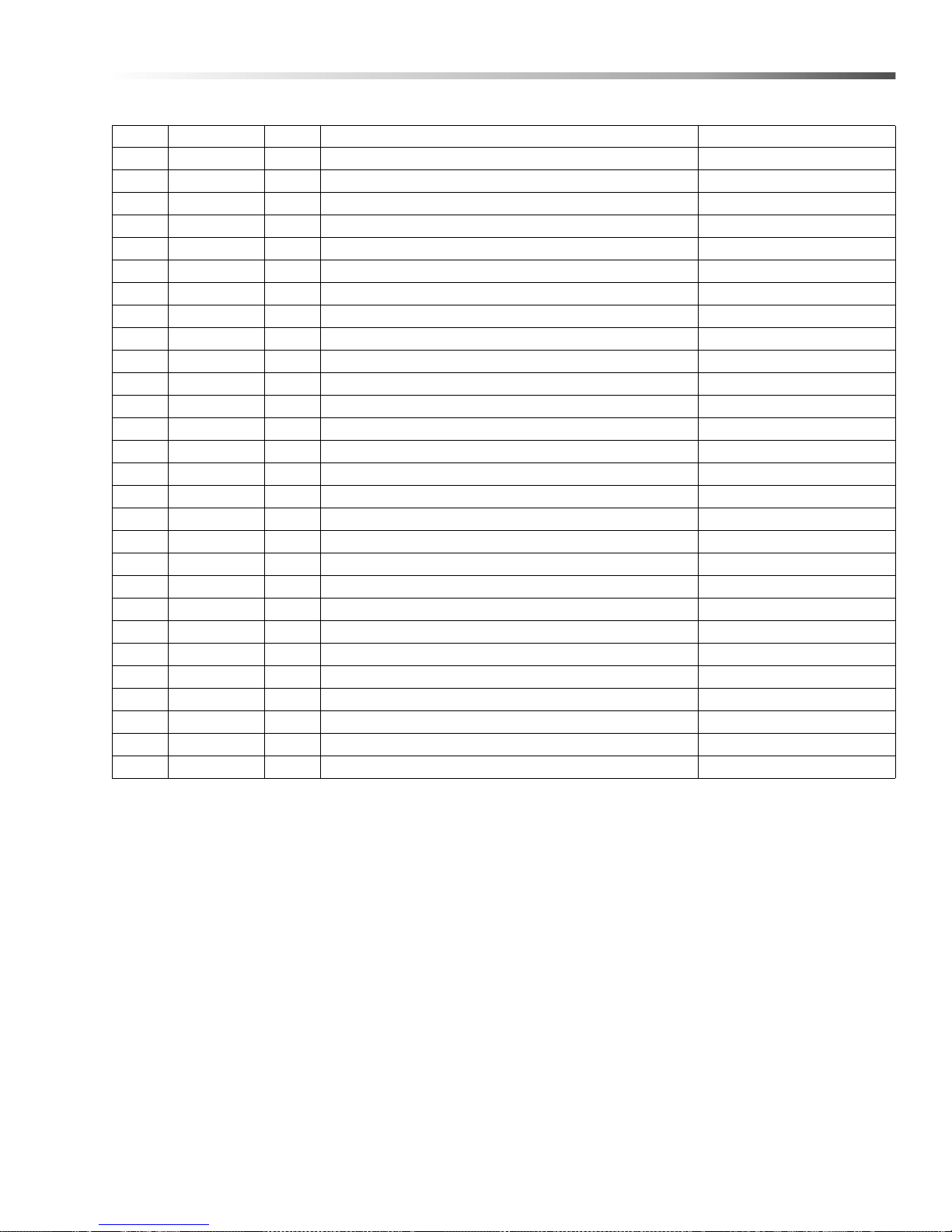
Option, Float Tank
REF PART NO. QTY DESCRIPTION NOTES
1 9.804-042.0 1 TANK, FLOAT 1-1/2 GAL
2 8.749-328.0 1 FLOAT VALVE, 1/2" KERICK
3 8.707-061.0 1 STRAINER, 1/2" BASKET
4 9.802-128.0 1 NIPPLE, 1/2" JIC X 1/2" PIPE
5 8.750-743.0 1 BULKHEAD, 1/2" POLYPRO
6 9.802-132.0 1 ELBOW, 3/4" JIC X 1/2"
7 9.802-146.0 1 SWIVEL, 1/2" MP X 3/4" GHF
8 8.707-000.0 1 CONNECTOR, 1/2" ANCHOR
9 8.706-512.0 1 BALL, FLOAT, BLACK PLASTIC
10 9.803-671.0 1 ROD, THREADED, 1/4" X 5
11 9.802-768.0 1 SCREW, 3/8" X 1-1/4" WHIZ
12 9.802-767.0 2 SCREW, 3/8" X 3/4" WHIZ
13 9.802-781.0 1 NUT, 3/8" FLANGE, WHIZ LOC
14 9.802-771.0 2 SCREW, 10/32" X 3/4"
15 9.802-695.0 2 NUT, 10/32" KEPS
16 8.916-457.0 2 STRAP, FLOAT TANK
17 8.916-448.0 1 WLMT, BASE, FLOAT TANK
18 8.916-446.0 1 WLMT, LID, FLOAT TANK
19 9.802-251.0 18" TUBE, CLEAR VINYL
20 9.802-753.0 2 SCREW, 1/4" X 3/4"
21 8.916-460.0 1 CHEMICAL, FRONT, PGDC
22 8.902-427.0 1 VAL VE, ASSY, CHEMICAL
23 8.916-492.0 1 LABEL, DETERGENT VALVE
24 9.802-252.0 68" TUBE, BRAIDED VINYL
25 9.802-251.0 72" TUBE, CLEAR VINYL
26 8.707-058.0 1 STRAINER W/CHECK VALVE
27 6.390-126.0 3 CLAMP
28 8.706-955.0 1 HOSE BARB, 1/4 BARB X 1/8" MPT
37Landa PGDC Operator’s Manual 8.916-596.0 - P
Page 38
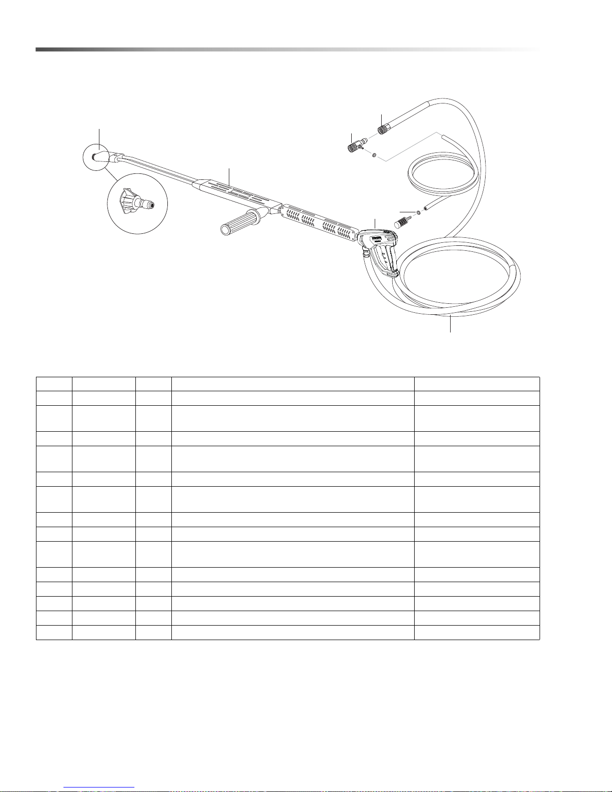
Hose & Spray Gun
2
7
1
8
5,6
4
3
High Pressure
Nozzle
REF PART NO. QTY DESCRIPTION NOTES
1 9.802-166.0 1 COUPLER, 3/8" FEMALE
- 9.802-100.0 1 O-RING, 3/8"
REPLACEMENT ONLY
NOT SHOWN
2 8.739-072.0 1 HOSE, 3/8" X 50', 2-WIRE TUFF-SKIN
3 4.775-054.0 1 EASY! FORCE ADVANCED KNA
1.110-049.0, 1.110-050.0,
1.110-051.0
- 8.751-234.0 1 GUN, LANDA, L1050, 5000 PSI, 10.4 GPM 1.110-072.0
4 8.711-293.0 1
WAND, UP ZNC (AL 344) W/CPLR
W/ SOAP NOZZLE
83-SSVPKIT 1 REPAIR KIT, AL STAINLESS STEEL
5 9.802-165.0 1 COUPLER, 1/4" MALE NOT SHOWN
- 9.802-096.0 1 O-RING
6 9.802-286.0 1 BRASS SOAP NOZZLE NOT SHOWN
REPLACEMENT ONLY
NOT SHOWN
7 9.802-216.0 1 DETERGENT INJECTOR ASSY
8 6.390-126.0 2 CLAMP, HOSE, .46-, .54 ST
9 8.707-139.0 1 COUPLER, 1/4"PLUG, MALE, STEEL/ZINC NOT SHOWN
10 9.802-164.0 1 COUPLER, 1/4"SOCKET, FEMALE, BRASS NOT SHOWN
38
Landa PGDC Operator’s Manual 8.916-596.0 - P
Page 39
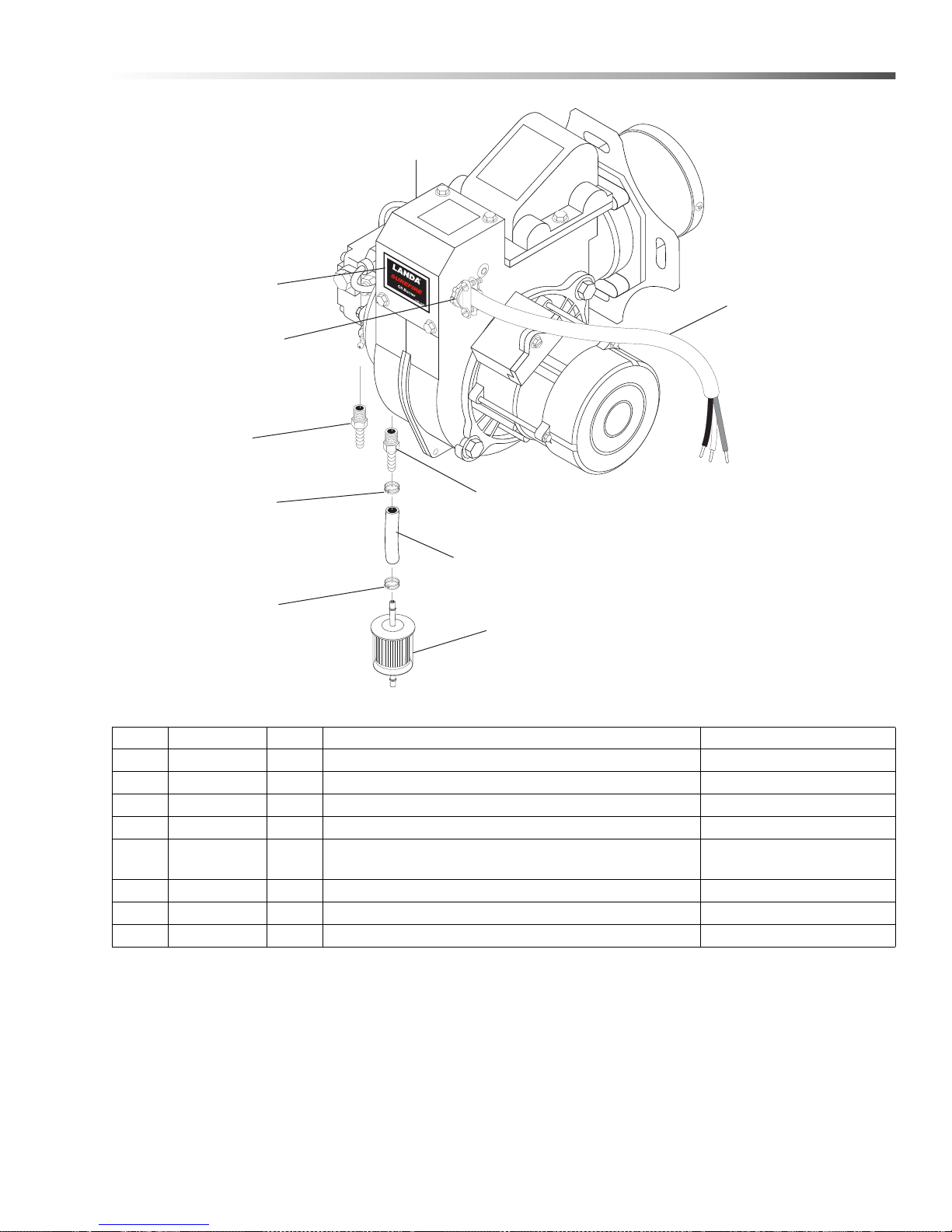
Burner
1
2
5
6
4
1
8
3
3
7
REF PART NO. QTY DESCRIPTION NOTES
1 8.709-069.0 2 CLAMP, SCREW, 5/16"W, 1/4-5/8" D, SS
2 9.802-254.0 5" HOSE, 1/4", PUSH-ON
3 8.706-941.0 1 HOSE BARB, 1/4" BARB X 1/4" ML
4 8.709-152.0 1 FILTER, DIESEL FUEL, DISPOSABLE
5 - - BURNER ASSEMBLY
6 9.802-519.0 1 STRAIN RELIEF, 2 SCREW 2 METAL 1/2"
SEE SPECIFICATIONS
PAGE
7 9.802-428.0 30" CORD, SERVICE, SJOWA 12/3
8 9.801-265.0 1 LABEL, LANDA SURE FIRE
39Landa PGDC Operator’s Manual 8.916-596.0 - P
Page 40
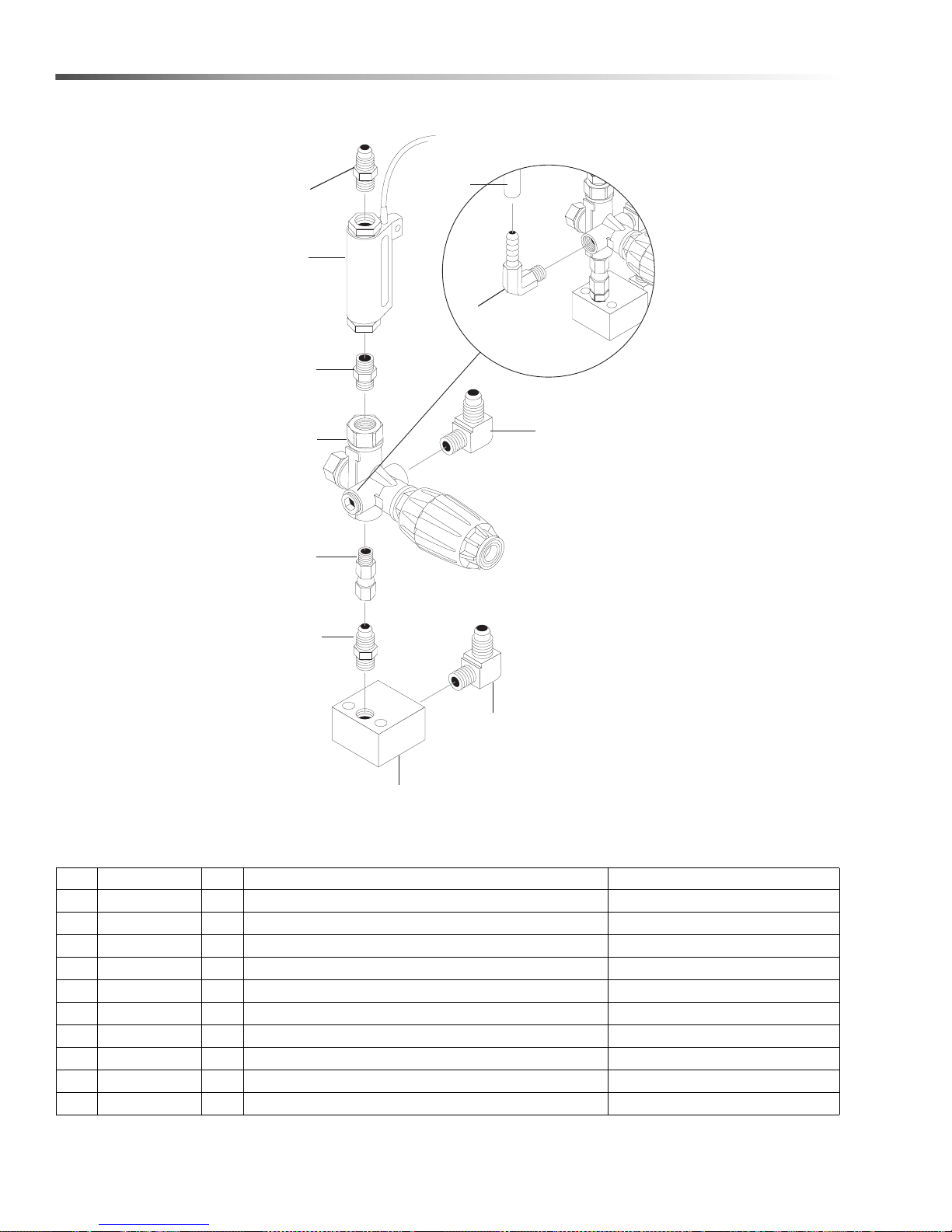
Unloader - 4-3500, 5-3500
1
2
3
7
10
5
6
8
4
4
9
Float Tank
Option Only
REF PART NO. QTY DESCRIPTION NOTES
1 9.802-039.0 1 ELBOW, 1/2" JIC X 3/8" MPT
2 9.802-870.0 1 BLOCK, UNLOADER, 3/8 X 3/8, 1.25 BRASS
3 9.802-048.0 1 SWIVEL, 1/2" JIC FEM, 3/8" MAL
4 9.802-036.0 2 NIPPLE, 1/2 JIC, 3/8 PIPE
5 9.802-129.0 1 ELBOW, 1/2" JIC X 3/8" 90°
6 8.750-299.0 1 UNLOADER VRT 3, 8 GPM @ 4500 PSI
7 8.933-006.0 1 SWITCH, FLOW MV60
8 8.705-974.0 1 NIPPLE, 3/8" HEX STEEL
9 8.706-965.0 1 HOSE BARB, 1/4" X 3/8" 90°
10 9.802-254.0 6 ft. HOSE, 1/4 PUSH-ON
40
Landa PGDC Operator’s Manual 8.916-596.0 - P
Page 41
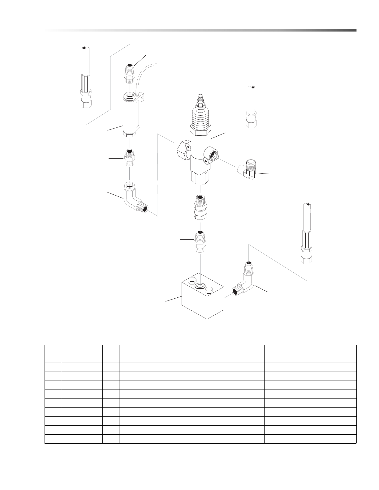
Unloader - 8-3000
7
10
5
6
8
9
2
1
3
4
REF PART NO. QTY DESCRIPTION NOTES
1 9.802-036.0 1 NIPPLE, 1/2" JIC X 3/8" MPT, STEEL
2 8.933-006.0 1 SWITCH, FLOW MV60
3 8.705-974.0 1 NIPPL E, 3/ 8" HEX STEEL -P/N-C3069X6
4 8.706-171.0 1 E LBO W, 1/2" MPT X 3/8" FPT STREET, STEEL
5 9.802-048.0 1 SWIVEL, 1/ 2" JIC FPT, 3/8" MPT STEEL
6 9.802-038.0 1 NIPPLE, 1/2" JIC X 3/8" MPT, STEEL
7 9.802-869.0 1 BLOCK, UNLOADER, 1/2 X 1/2, 1.75, STEEL
8 8.712-708.0 1 UNLOADER VALVE (GIANT 22913) 30
9 9.802-132.0 1 ELBOW, 3/4" MSAE X 1/2" MPT, BRASS
10 9.802-040.0 1 ELBOW, 1/2 JIC, 1/2, 90°-P/TF5405-8-8
41Landa PGDC Operator’s Manual 8.916-596.0 - P
Page 42
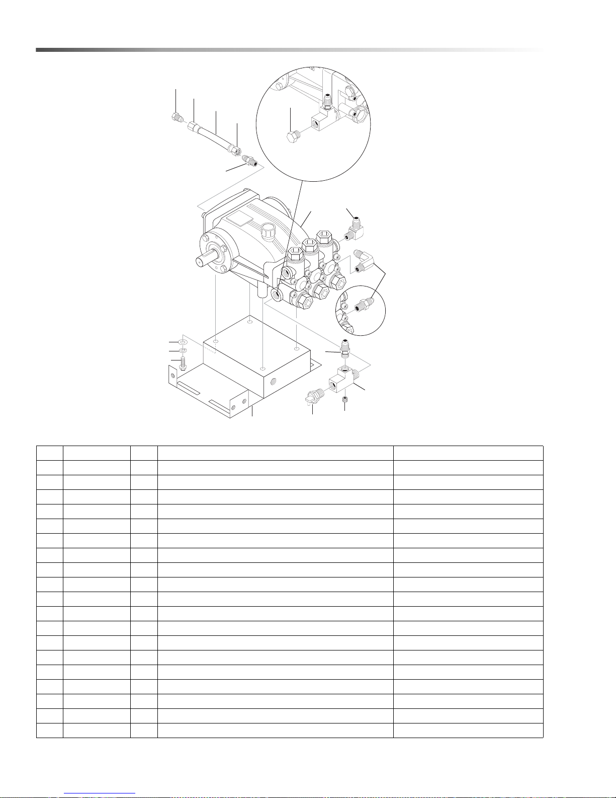
Pump
1
2
3
4
5
6
7
8
14
15
16
11
10
12
10
13
9
Float Tank
Option Only
REF PART NO. QTY DESCRIPTION NOTES
1 8.921-713.0 1 PUMP, LT6036L (1.110-051.0 1.110-050.0)
- 8.921-711.0 1 PUMP, LT4540L (1.110-049.0)
- 8.920-590.0 1 PUMP, LANDA LX9536L.2, 9.5@3625 1740RPM (1.110-072.0)
2 8.912-461.0 1 ASSY, GAS PUMP PLATE
3 9.802-123.0 1 TEE, 1/2" W/ (1) HOLE
4 8.706-864.0 1 PLU G, 1/ 8" CO UNT ERSU NK
5 8.707-256.0 1 PUMP PROTECTOR, 1/2"
6 9.802-128.0 1 NIPPLE, 1/2" X 1/2" MPT PIPE
7 9.802-039.0 1 ELBOW, 1/2" JIC X 3/8" MPT
8 9.802-132.0 1 ELBOW, 3/4" JIC X 1/2" 90°
- 8.706-902.0 1 NIPPLE, 3/4" JIC X 1/2" PIPE (TR3500/6000 OPTION)
9 9.802-127.0 1 NIPPLE, 1/2" JIC X 3/8 PIPE
10 9.802-151.0 2 SWIVEL 1/2" PUSH-ON
11 9.802-126.0 1 PLUG, 1/2" JIC
12 9.802-259.0 20" HOSE, 1/2" PUSH-ON
13 8.706-868.0 1 PLUG, 1/2"
14 9.802-744.0 4 BOLT, 10MM X 20MM, ZINC
15 8.718-961.0 4 WASHER, M10, SPLIT ZINC
16 9.802-807.0 4 WASHER 3/8" FLAT ZINC
42
Landa PGDC Operator’s Manual 8.916-596.0 - P
Page 43
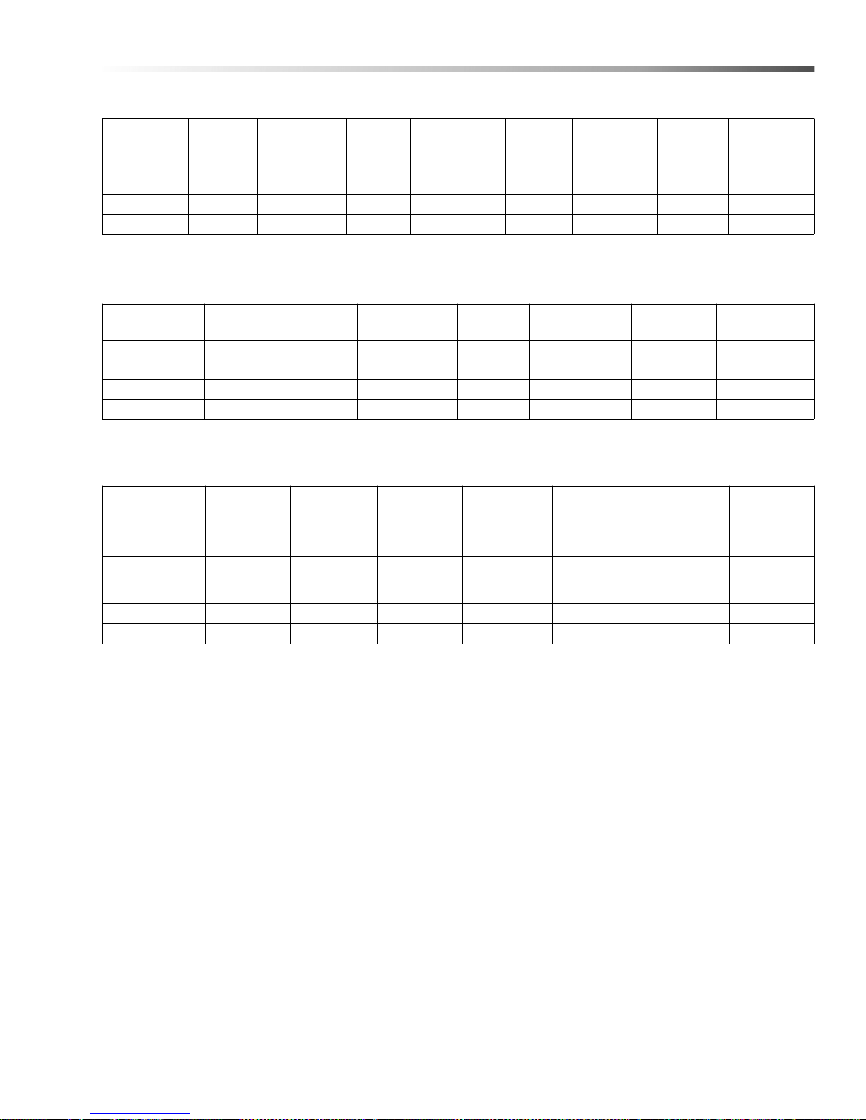
Pump
Specifications
Machine
Model
Pump
Model
Part # Pulley Pulley Part # Bushing
Bushing
Part #
Belt
Size/Qty
Belt Part #
1.110-049.0 LT4540/L 8.921-711.0 2BK90 8.715-593.0 25mm 9.802-403.0 BX36 (2) 8.715-697.0
1.110-050.0 LT6036/L 8.921-713.0 2BK90 8.715-593.0 25mm 9.802-403.0 BX36 (2) 8.715-697.0
1.110-051.0 LT6036/L 8.921-713.0 2BK90 8.715-593.0 25mm 9.802-403.0 BX36 (2) 8.715-697.0
1.110-072.0 LX9536/L 8.920-590.0 2BK80 8.715-592.0 25mm 9.802-403.0 BX37 (2) 8.715-698.0
Engine
Model Model Part # Pulley Pulley Part # Bushing
1.110-049.0 Honda
1.110-050.0 Briggs
1.110-051.0 Honda
1.110-072.0 Honda
GX390(389cc) 8.750-579.0 2BK32H 9.802-381.0 Hx1” 9.802-399.0
Vanguard(570cc) 8.754-819.0 2BK32H 9.802-381.0 P2x1" 9.802-404.0
GX630(688cc) 8.752-149.0 2BK32H 9.802-381.0 P2x1" 9.802-404.0
GX630 (688cc) 8.752-149.0 2BK36H 9.802-383.0 P2x1-1/8" 9.802-405.0
Bushing Part
#
Landa Sure Fire Burner Specifications
Fuel Nozzle
Model
Number
1.110-049.0 8.918-919.0 8.754-889.0 8.919-116.0 8.751-074.0 8.754-705.0 9.802-562.0 8.750-778.0
1.110-050.0 8.918-919.0 8.754-889.0 8.919-116.0 8.751-074.0 8.754-705.0 9.802-562.0 8.750-778.0
1.110-051.0 8.918-919.0 8.754-889.0 8.919-116.0 8.751-074.0 8.754-705.0 9.802-562.0 8.750-778.0
1.110-072.0 8.918-919.0 8.754-889.0 8.919-116.0 8.751-074.0 8.754-705.0 9.802-562.0 8.750-778.0
Burner
Assy No.
w/100 psi
Check
Valve
Igniter Motor Fuel Pump Solenoid
Coil
Electrode
43Landa PGDC Operator’s Manual 8.916-596.0 - P
Page 44
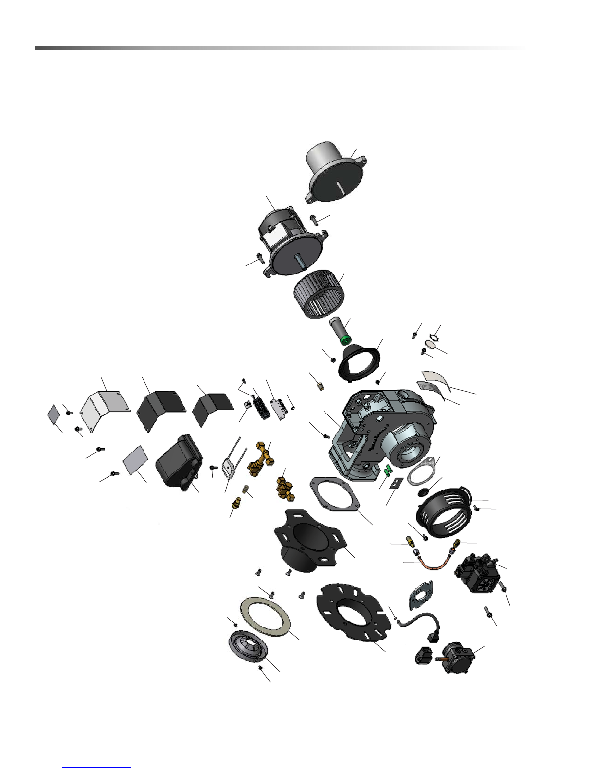
Landa Sure Fire Burner
Replacement Parts
For best performance specify genuine KNA replacement parts
28
36
36
1
1
31
36
47
30
16
15
22
33
33
40
17
14
3
27
5
5
48
45
49
29
46
39
39
7
7
8
9
2
38
32
36
4
44
6
36
36
12
11
13
3
39
39
23
21
20
18
19
10
35
34
43
37
37
37
25
24
41
26
44
Landa PGDC Operator’s Manual 8.916-596.0 - P
Page 45
Landa Sure Fire Burner
REF PART NO. QTY DESCRIPTION NOTES
1 8.919-050.0 1 BURNER HOUSING ASSEMBLY
2 8 .751-160.0 1 A IR GUIDE
3 8.754-705.0 1 FUEL PUMP, SUNTEC OL35 12-24 V SOL
- 8.700-759.0 1 FUEL PUMP, SUNTEC A2VA-3106 120 V SOL
- 8.700-760.0 1 FUEL PUMP, SUNTEC A2VA-3106 120 V SOL
4 9.807-348.0 1 LABEL, CLEAR MYLAR
5 9.802-510.0 2 CABLE, TIE, 4" BLACK
6 8 .750-541.0 1 AIR BAND
7 8.750-517.0 1 MOTOR,1/6 HP 115V 60HZ
- 8.750-518.0 1 MOTOR,1/6 HP 230V 60HZ
- 8.750-074.0 1 MOTOR,1/7 HP 12VDC AMETEK
8 8.750-543.0 1 COUPLING, FLEX, 1/2" X 5/16"
- 8.751-073.0 1 COUPLING, FLEX, 5/16" X 5/16"
9 8.750-520.0 1 FAN, 4.53" X 2.42",1/2" BORE, F115-62S
- 8.751-072.0 1 FAN, 4.53" X 2.42", .313 BORE, F115-625
10 8.900-083.0 1 100 PSI SNAP CHECK VALVE
11 8.750-547.0 1 CONNECTOR, 37° FLARE X 1/8” NPT, LONG
12 8.750-545.0 1 CONNECTOR, 37° FLARE X 1/8” NPT
13 8.749-000.0 1 FUEL LINE ASSEMBLY
14 8.752-034.0 1 FLANGE, KNA BURNER, 1” TUBE
15 8.752-035.0 1 FLANGE, KNA BURNER, 3” TUBE
16 8.750-539.0 1 GASKET, FLANGE
17 8.751-354.0 1 GASKET, BURNER TUBE
18 8.750-526.0 1 GUN, ELECTRODE/NOZZLE, 3"
19 8.750-525.0 1 GUN, ELECTRODE/NOZZLE, 1"
20 8.717-273.0 1 FUEL NOZZLE 2.00 X 90 B
21 8.750-778.0 1 ELECTRODE, IGNITION, AC
- 8.751-342.0 1 ELECTRODE, IGNITION, DC
22 8.750-779.0 1 CONE, AIR F4
- 8.750-782.0 1 CONE, AIR F6
- 8.750-780.0 1 CONE, AIR F12
- 8.750-781.0 1 CONE, AIR F22
23 8-919-114.0 1 IGNITER, BURNER 120V
- 8-919-115.0 1 IGNITER, BURNER 230V
- 8-919-116.0 1 IGNITER, BURNER 12VDC
24 8.751-165.0 1 PLUG, HOLE 0.875 PLASTIC
25 8.754-905.0 1 GASKET, KNA BURNER PUMP SUNTEC
26 8.751-134.0 1 PLUG, 1/8" NPT X HEX SHOULDER
27 8.918-454.0 1 GASKET, JUNCTION BOX
28 8.750-542.0 1 COVER, JUNCTION BOX
29 8.750-116.0 1 BLOCK, TERMINAL, 5 POLE
45Landa PGDC Operator’s Manual 8.916-596.0 - P
Page 46
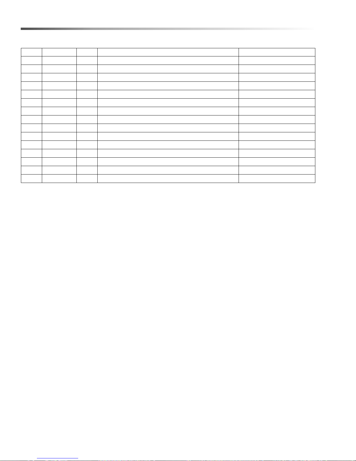
Landa Sure Fire Burner
REF PART NO. QTY DESCRIPTION NOTES
30 8.750-817.0 2 LIGHT, INDICATOR, GREEN,14V
- 8.750-818.0 1 LIGHT, INDICATOR, GREEN, 28V
- 8.750-819.0 1 LIGHT, INDICATOR, GREEN, 125V
- 8.750-820.0 1 LIGHT, INDICATOR, GREEN, 250V
31 8.750-784.0 1 SITE GLASS
32 8.750-785.0 1 RING, PUSH ON INTERNAL, 1305-112
33 8.733-001.0 2 SCREW, 8 X 1/4" HI LOW THREAD CUT PPH
34 8.718-762.0 2 SCREW, 8-32 X 1/2",M PH RDH PL
35 9.807-345.0 1 LABEL, IGNITER 120V
- 9.807-346.0 1 LABEL, IGNITER 230V
- 9.807-347.0 1 LABEL, IGNITER 12VDC
36 8.718-810.0 6 SCREW, 10/32 X 1/2", WHIZ LOC FLANGE
37 8.750-770.0 3 SCREW, 10/32 X 5/8", WHIZ LOC FLANGE
38 8.750-816.0 1 SCREW, 10/32 X 1/4", GROUNDING
39 8.750-768.0 4 SCREW, 1/4-20 X 1", PHIL FHMS
46
Landa PGDC Operator’s Manual 8.916-596.0 - P
Page 47
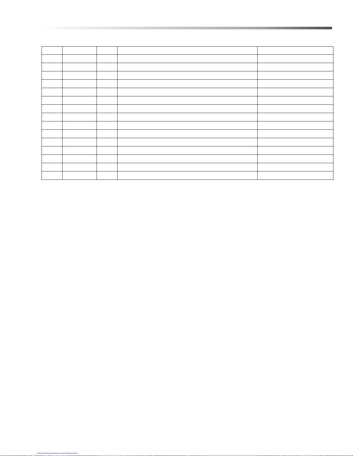
Landa Sure Fire Burner
REF PART NO. QTY DESCRIPTION NOTES
40 8.750-771.0 4 SCREW, 1/4-20 X 1/2", WHIZ LOC
41 9.802-745.0 1 SCREW, 10/32 X 1/2" SHCS
42 - 1 LABEL, BRAND NAME NOT SHOWN
43 9.801-268.0 1 LABEL, DISCONNECT POWER SUPPLY
44 - 1 LABEL, SERIAL PLATE
45 8.750-830.0 1 PLUG, HOLE 0.285 PLASTIC
46 9.807-339.0 1 LABEL, WIRING DIAGRAM, BURNER 115V-115V
- 9.807-340.0 1 LABEL, WIRING DIAGRAM, BURNER 230V-230V
- 9.807-341.0 1 LABEL, WIRING DIAGRAM, BURNER 230V-115V
- 9.807-342.0 1 LABEL, WIRING DIAGRAM, BURNER 115V-24V
- 9.807-343.0 1 LABEL, WIRING DIAGRAM, BURNER 230V-24V
- 9.807-344.0 1 LABEL, WIRING DIAGRAM, BURNER 12VDC
47 9.801-274.0 1 LABEL, BURNER LIGHTS
48 8.919-105.0 1 PLATE, TERMINAL BLOCK NUMBERS
49 8.716-451.0 1 TERMINAL, JUMPER SPADE
47Landa PGDC Operator’s Manual 8.916-596.0 - P
Page 48
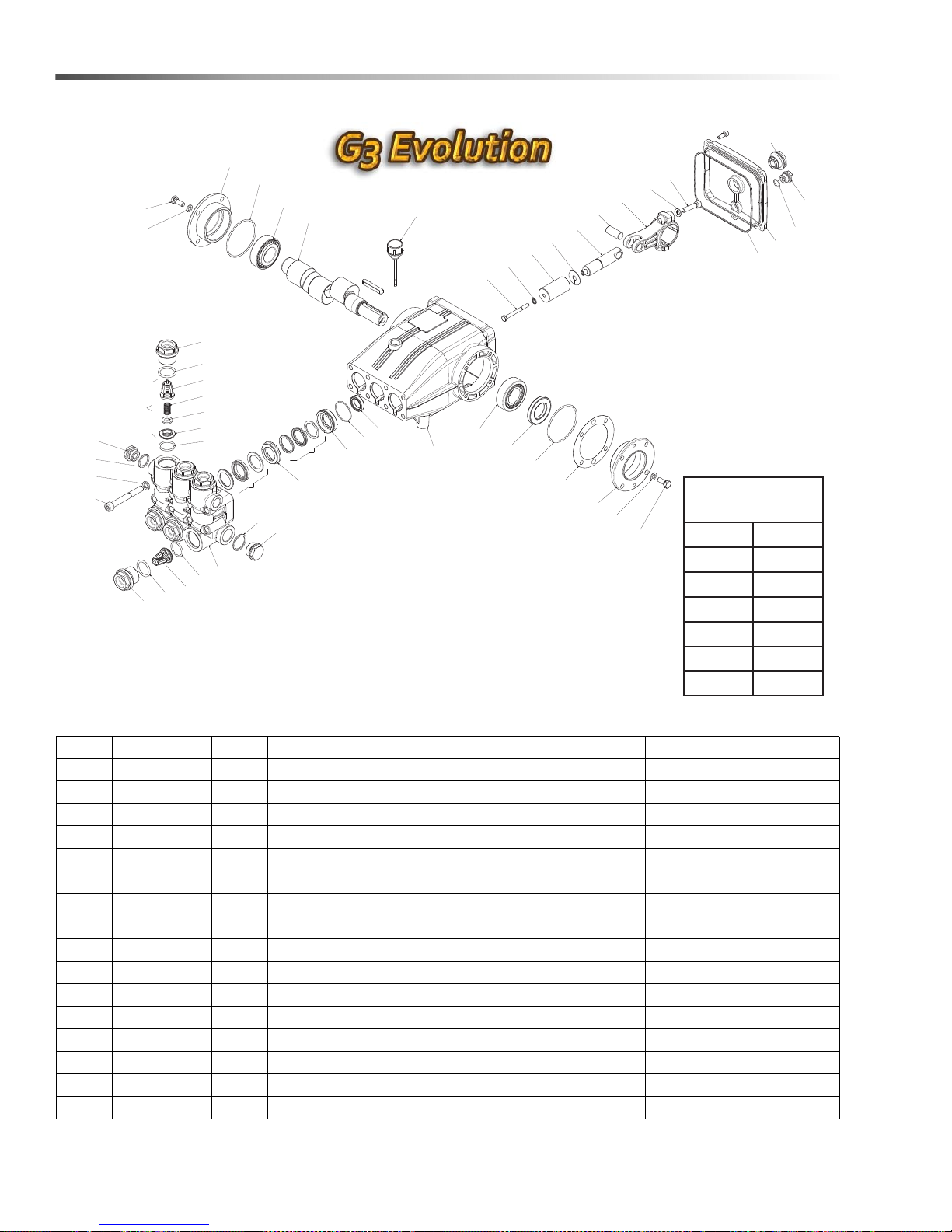
LT.2 Series Pump
TORQUE SPECS
ITEM # FT. LBS.
14 95
15 45
23 8
34 10
42 30
48 8
5
7
12
12
23
24
25
26
27
28
29
30
27
31
26
32
33
24
23
34
35
36
37
38
39
40
41
42
43
44
45
46
47
48
2
3
4
6
8
9
10
13
14
15
16
17
18
19
20
21
22
13
14
11
11
1
REF PART NO. QTY DESCRIPTION NOTES
1 8.752-825.0 1 CRANKCASE
2 - 3 PLUNGER OIL SEAL SEE KITS TABLE
3 - 3 O-RING Ø1.78 X 37.82 SEE KITS TABLE
4 - 3 PRESSURE RING, 18MM SEE KITS TABLE
5 - 3 U-SEAL, 18MM SEE KITS TABLE
6 - 3 INTERMEDIATE RING, 18MM SEE KITS TABLE
7 - 3 U-SEAL, 18MM SEE KITS TABLE
8 9.802-926.0 1 BRASS PLUG, G1/2
9 9.803-199.0 1 COPPER WASHER 1/2
10 8.753-816.0 1 MANIFOLD HOUSING
11 9.804-498.0 6 O-RING Ø2.62 X 25.1 SEE KITS TABLE
12 - 6 VAL VE ASSEMBL Y SEE KITS TABLE
13 9.803-193.0 6 O-RING 3068 SEE KITS TABLE
14 9.802-928.0 6 VALVE PLUG
15 8.753-817.0 8 MANIFOLD STUD BOLT
16 9.802-890.0 8 LOCK WASHER
48
Landa PGDC Operator’s Manual 8.916-596.0 - P
Page 49
LT.2 Series Pump
REF PART NO. QTY DESCRIPTION NOTES
17 8.719-008.0 1 COPPER WASHER 3/8
18 8.707-262.0 1 BRASS PLUG 3/8
19 - 6 VALVE SEAT SEE KITS TABLE
20 - 6 VALVE PLATE SEE KITS TABLE
21 - 6 VALVE SPRING SEE KITS TABLE
22 - 6 VALVE CAGE SEE KITS TABLE
23 8.752-830.0 8 HEX SCREW
24 9.802-884.0 8 WASHER
25 9.803-182.0 1 CLOSED BEARING HOUSING
26 9.803-186.0 2 O-RING Ø2.62 X 71.12
27 9.803-160.0 2 ROLLER BEARING
28 8.753-818.0 1 CRANKSHAFT Ø25 (4540)
- 8.752-827.0 1 CRANKSHAFT Ø25 (6036)
29 9.803-167.0 1 CRANKSHAFT KEY
30 8.752-834.0 1 OIL DIP STICK
31 9.803-139.0 1 CRANKSHAFT SEAL
32 9.803-177.0 2 SHIM
33 9.803-181.0 1 BEARING HOUSING
34 8.752-841.0 3 PLUNGER BOLT SEE KITS TABLE
35 8.752-820.0 3 BONDED SEAL SEE KITS TABLE
36 8.753-819.0 3 PLUNGER, 18MM SEE KITS TABLE
37 8.752-823.0 3 COPPER SPACER SEE KITS TABLE
38 8.753-820.0 3 PLUNGER ROD
40 8.752-821.0 3 CONNECTING ROD
41 9.802-889.0 6 SPRING WASHER
42 9.802-937.0 6 CONNECTING ROD SCREW
43 9.803-194.0 1 O-RING Ø2.62 X 152.07
44 8.752-826.0 1 CRANKCASE COVER
45 9.803-906.0 1 O-RING Ø1.78 X 14.00
46 8.707-262.0 1 BRASS PLUG G3/8
47 9.803-202.0 1 SIGHT GLASS G3/4
48 8.752-824.0 5 COVER SCREW
KIT NUMBERS 8.753-821.0 8.753-822.0 8.753-823.0 8.753-824.0 8.752-835.0
KIT DESCRIPTION
ITEMS NUMBERS
INCLUDED
NO. OF CYLINDERS KIT
WILL SERVICE
Plunger Seals
Seal Packing
18 mm
3, 5, 7 3, 4, 5, 6, 7, 34, 35, 36, 37 11, 12, 13 2
31163
18 mm
Plunger
18 mm
Complete Valve
Plunger Oil
Seals
49Landa PGDC Operator’s Manual 8.916-596.0 - P
Page 50
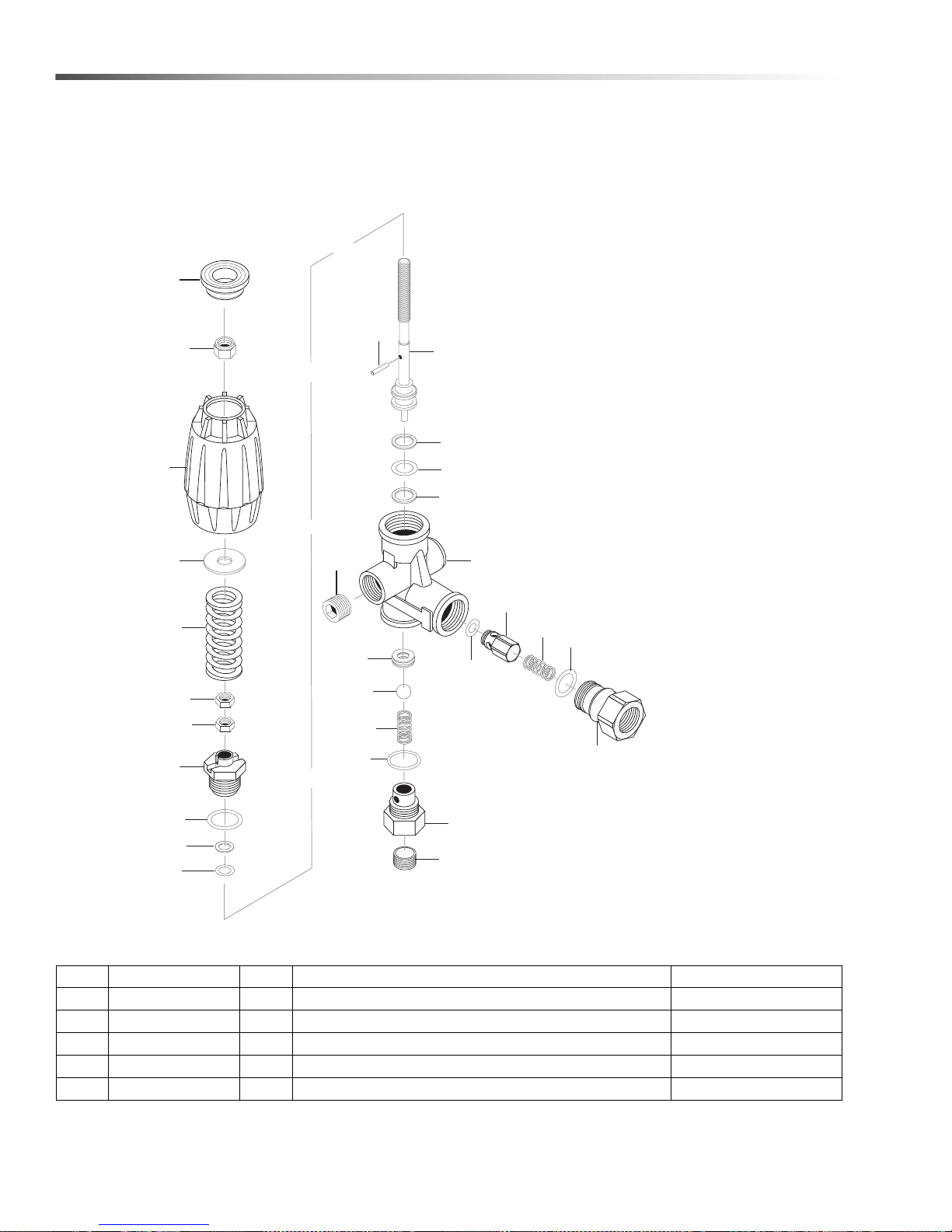
VRT3 Unloader
8.750-297.0, 8 GPM, 2320 PSI
8.750-298.0, 8 GPM, 3630 PSI
8.750-299.0, 8 GPM, 4500 PSI
9
8
23
26
2
3
16
1
10
24
11
6
4
13
14
20
25
12
22
19
15
15
21
17
18
7
9
5
6
REF PART NO. QTY DESCRIPTION NOTES
25 8.750-713.0 1 OUTLET FITTING
18 8.750-712.0 1 KNOB, UNLOADER
- 8.750-709.0 - REPAIR KIT, VRT3, 2320/3630 PSI
- 8.750-710.0 - REPAIR KIT, VRT3, 4500 PSI
- - - (KIT ITEMS: 3, 4, 6, 9-12, 21, 24)
50
Landa PGDC Operator’s Manual 8.916-596.0 - P
Page 51

VRT3 Unloader
Unloader Adjustment Procedures
1. Remove lock nut (Item 19).
2. Remove adjustment knob (Item 18).
3. Loosen the two (2) nuts (Item 15), move them upward on stem (Item 8) until you see 4 or more threads below
the nut.
4. Re-attach adjusting knob (Item 18).
5. Start machine. Open the trigger of the spray gun. Increase pressure by turning adjustment knob (Item 18)
clockwise until pressure is at the desired operating pressure.
6. Remove the adjustment knob (Item 18), tighten the lower nut (Item 15) tightly against the upper nut (Item 15).
Re-attach adjustment knob (Item 18) and screw down until contact is made with the nuts (Items 15). Screw
down lock nut (Item 19) onto the stem (Item 8) until the threads cut into the nylon insert of the lock nut
(Item19).
*If adjustment knob (Item 18) DOES NOT make contact with upper nut (Items 15), remove adjusting knob (Item
18), re-adjust (raise) nuts (Items 15) on stem (Item 8) and re-attach adjustment knob (Item 18), then repeat
step #6.
**If adjustment knob (Item 18) DOES make contact with upper nut; release the trigger of the spray gun and
watch the pressure gauge for the pressure increase (“spike”). This “spike” SHOULD NOT exceed 500 psi
above the operating pressure. If “spike” pressure exceeds the 500 psi limit, remove the adjusting knob (Item
18) and re-adjust (lower) the nuts (Items 15) on the stem (Item 8). Re-attach the adjusting knob (Ite m 18), then
repeat step #6.
51Landa PGDC Operator’s Manual 8.916-596.0 - P
Page 52

8.916-596.0 • Printed in U.S.A.
 Loading...