

Page 1

Arc
Thermal Imaging Camera
© Land Instruments International, 2011
Installation Guide
Issue 3, August 2011
Publication Nº 806549
Language: English
Page 2

Page 3
Equipment Operation
Use of this instrument in a manner not specied by Land Instruments International may be hazardous.
Electrical Power Supply
Before working on the electrical connections all of the electrical power lines to the equipment must be isolated. All the
electrical cables and signal cables must be connected exactly as indicated in these operating instructions. If in doubt contact
Land Instruments International.
Face and Eye Protection
Suitable face and eye protection must be worn when working on hot vessels and ducts! Special safety measures must be
taken when working on a high-pressure duct.
Protective Clothing
Protective clothing must always be worn when working in the vicinity of hot vessels or ducts.
Storage
The instrument should be stored in its packaging, in a dry sheltered area.
Unpacking
Check all packages for external signs of damage. Check the contents against the packing note.
Return of Damaged Goods
IMPORTANT
If any item has been damaged in transit, this should be reported to the carrier and to the supplier immediately. Damage
caused in transit is the responsibility of the carrier not the supplier.
DO NOT RETURN a damaged instrument to the sender as the carrier will not then consider a claim. Save the packing with the
damaged article for inspection by the carrier.
Return of Goods for Repair
If you need to return goods for repair please contact our Customer Service Department. They will be able to advise you on
the correct returns procedure.
Any item returned to Land Instruments International should be adequately packaged to prevent damage during transit.
You must include a written report of the problem together with your own name and contact information, address, telephone
number, email address etc.
Return of Goods for Repair Form is available for download from our websites.
Lifting Instructions
Where items are too heavy to be lifted manually, use suitably rated lifting equipment. Refer to the Technical Specication for
weights. All lifting should be done as stated in local regulations.
Design and Manufacturing Standards
The Quality Management System of Land Instruments International is approved to
BS EN ISO 9001 for the design, manufacture and on-site servicing of combustion,
environmental monitoring and non-contact temperature measuring instrumentation.
Approvals apply in the USA
This instrument complies with current European directives relating to
Electromagnetic Compatibility 89/336/EEC and Low Voltage Directive
73/23/EEC.
Operation of radio transmitters, telephones or other electrical/electronic devices
in close proximity to the equipment while the enclosure doors of the instrument
or its peripherals are open, may cause interference and possible failure where the
radiated emissions exceed the EMC directive.
The protection provided by both CE and IP classications to this product may
be invalidated if alterations or additions are made to the structural, electrical,
mechanical or pneumatic parts of this system. Such changes may also invalidate
the standard terms of warranty.
Dimensions
Unless otherwise stated, all measurements are given in millimetres and inches.
Copyright
This manual is provided as an aid to owners of Land Instruments International’s
products and contains information proprietary to Land Instruments International.
This manual may not, in whole or part, be copied, or reproduced without the
expressed written consent of Land Instruments International Ltd.
Copyright © 2007 - 2011 Land Instruments International.
Signs and Symbols Used on
Equipment and Documentation
Observe precautions for handling electrostatic discharge sensitive
devices.
Protective Conductor Terminal.
This item or material must be disposed of in accordance
with the Waste Electrical and Electronic Equipment
directive as applied by local regulations.
This item or material can be recycled.
Caution, hot surface.
Caution, attention to possibility of risk of damage to the product,
process or surroundings. Refer to instruction manual.
Caution, risk of electric shock.
Ofce Locations
UK - Droneld
Tel: +44 (0) 1246 417691
E-Mail: [email protected]
Web: www.landinst.com
USA - Pittsburgh
AMETEK Land, Inc.
Tel: +1 412 826 4444
E-Mail: [email protected]
Web: www.ametek-land.com
For further details on all LAND/
Ametek ofces, distributors and
representatives, please visit our
websites.
Important Health and Safety Information
IMPORTANT INFORMATION - PLEASE READ
Page 4

Arc Thermal Imaging Camera Installation Guide
Page 5

Arc Thermal Imaging CameraInstallation Guide
Contents
1 Introduction 1
1.1 Points to note on installation 1
1.2 Using compressed air for air purging 1
2 Specications 2
2.1 LED Status Indicators 2
3 Installation diagrams 3
System Diagram & Electrical Connections 4
Camera Dimensions 5
Housing Assembly Instructions 6
Housing Dimensions 7
Pan & Tilt Dimensions 8
Weather Cover Dimensions 9
Page 6

Arc Thermal Imaging Camera Installation Guide
Page 7

Arc Thermal Imaging CameraInstallation Guide
Page 1
1 Introduction
This guide gives you information on how to install the ARC thermal imaging camera
and its installation accessories.
These instructions are provided as a series of simple installation diagrams, covering
the installation of the Arc thermal camera and its mountings, accessories and
services.
The equipment must be used, maintained and serviced by properly trained personnel,
capable of following the procedures given in these instructions. Safety may be
impaired if the system is not used as indicated.
It is important to check the equipment with which you have been supplied and then
read these instructions thoroughly before proceeding with installation.
1.1 Points to note on installation
• When choosing a location to install the Arc thermal imaging camera, ensure that
the camera has an unobstructed view of the target to be measured.
• Try to choose a mounting location that permits easy access to the system
components wherever possible, as this will speed up any system maintenance
and repair.
• Ensure that the mounting locations chosen for the camera and its accessories
are as free as possible from vibration, dust, steam and smoke etc.
• Ensure that the mounting locations chosen for the camera and its accessories
allow for the lengths of interconnecting cables that you have ordered. Also,
ensure that all cable runs are as secure and unobtrusive as possible.
1.2 Using compressed air for air purging
If your application requires the use of the air purging and you intend to use
compressed air to supply air to the purge, then the following points must be noted:
• If possible, connect the compressed air supply to the purge via a 1m length of
35mm diameter smooth bore tube. This will increase the air ow rate slightly.
• The minimum recommended air pressure is 20 psi (1.4 bar).
• The minimum recommended ow rate is 350 l/min.
• Occasional cleaning will be required to prevent the build up of everyday dirt on
site when the purge is off.
Page 8
Arc Thermal Imaging Camera Installation Guide
Page 2
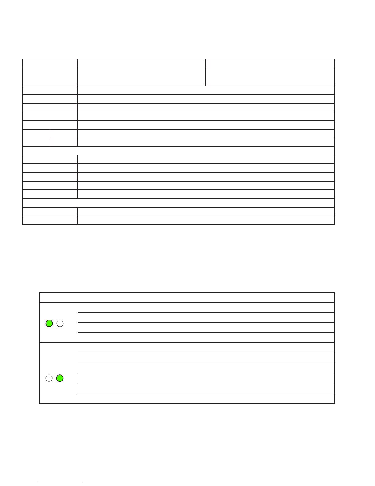
2.1 LED Status Indicators
The LEDs on the rear face of the Arc Thermal Imaging Camera are used to indicate
the status of the camera operation.
The table below gives an explanation of the LEDs.
LED Colour Meaning
LED1 Orange Camera Settling
Green On
Blink Off Ethernet Command Event
Blink Red Shutter Event
LED2 Off I/O Disabled
Flashing Orange Connecting to I/O
Flashing Green/Orange Connected to I/O
Green Logged in to I/O
Blink Off I/O Update Event
Blink Red I/O Watchdog Event
2 Specifications
Model Range ARC-8-FOV-500-Rate ARC-8-FOV-1000-Rate
Temperature Range
0 to 500°C
32 to 932°F
100 to 1000°C
212 to 1832°F
Spectral Response 8 - 14µm
Image resolution 384 x 288
Horizontal FOV 11°, 22°, 44° or 60°
Focus range 0.3m>innity (22°, 44°, 60°) / 0.5m>innity (11°)
Accuracy ±2% or ±2°C
Frame
Rate
LF 7.5 Hz (export licence-free)
HF 30 Hz
Physical & Environmental
Dimensions 85 x 85 x 276 mm / 3.5 x 3.5 x 11 in (including lens)
Weight 1.8 kg / 4 lb
Ambient Range -20 to 60°C / -4 to 140°F
Operating Humidity 5% to 95% (non-condensing)
Sealing IP65 / NEMA 4X
Power I/O and EMC
Power Supply 9 to 30 Vdc
EMC EN 61326
Page 9

Arc Thermal Imaging CameraInstallation Guide
Page 3
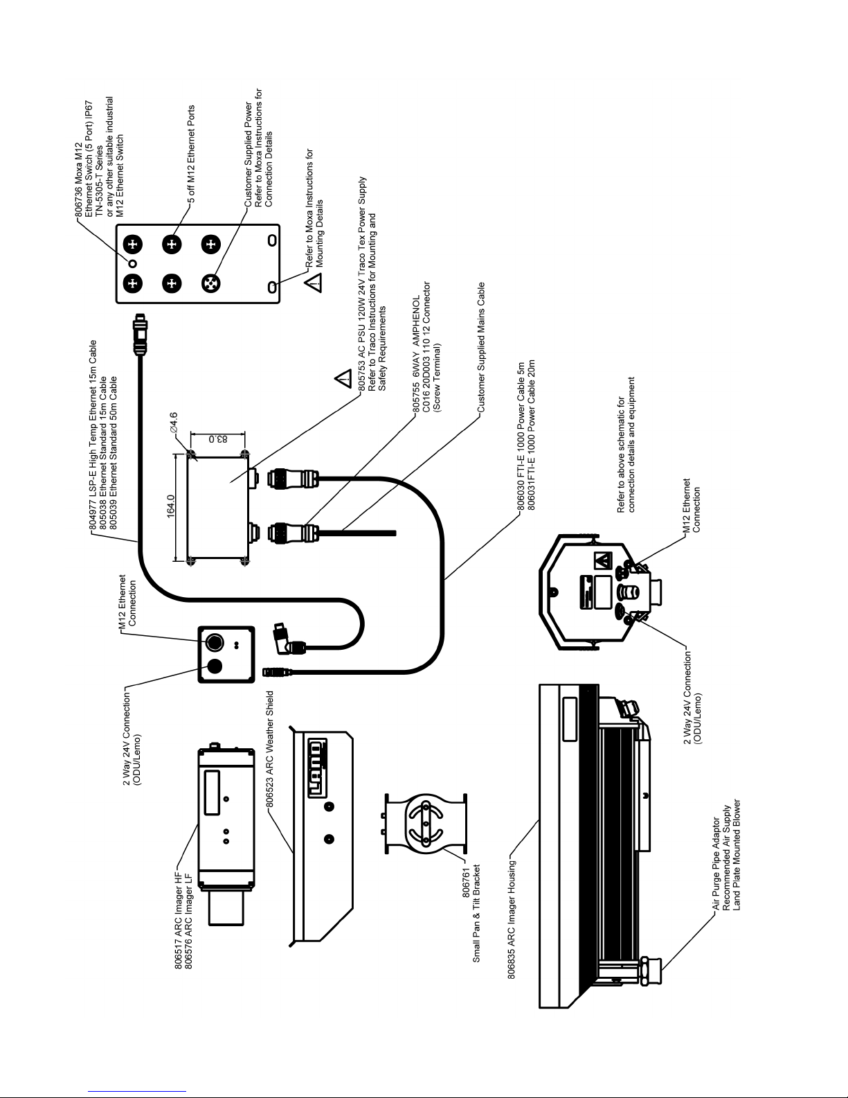
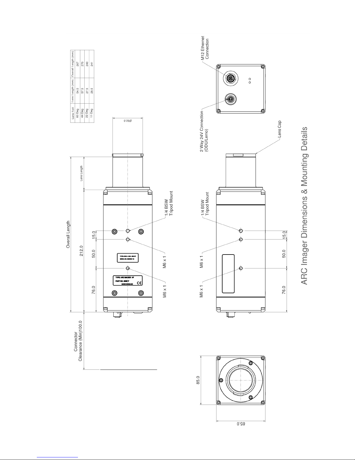
3 Installation diagrams
This Installation Guide provides a series of simple installation diagrams, covering the
installation of the Arc thermal camera and its mountings, accessories and services.
Page 10
Arc Thermal Imaging Camera Installation Guide
Page 4
Page 11
Arc Thermal Imaging CameraInstallation Guide
Page 5
Page 12
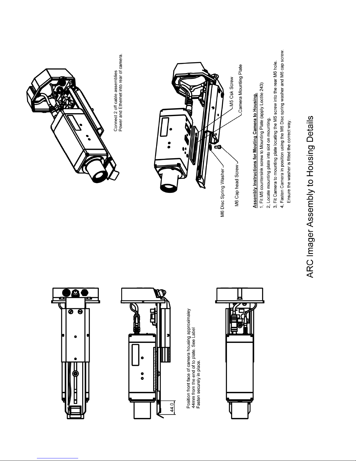
Arc Thermal Imaging Camera Installation Guide
Page 6
Page 13
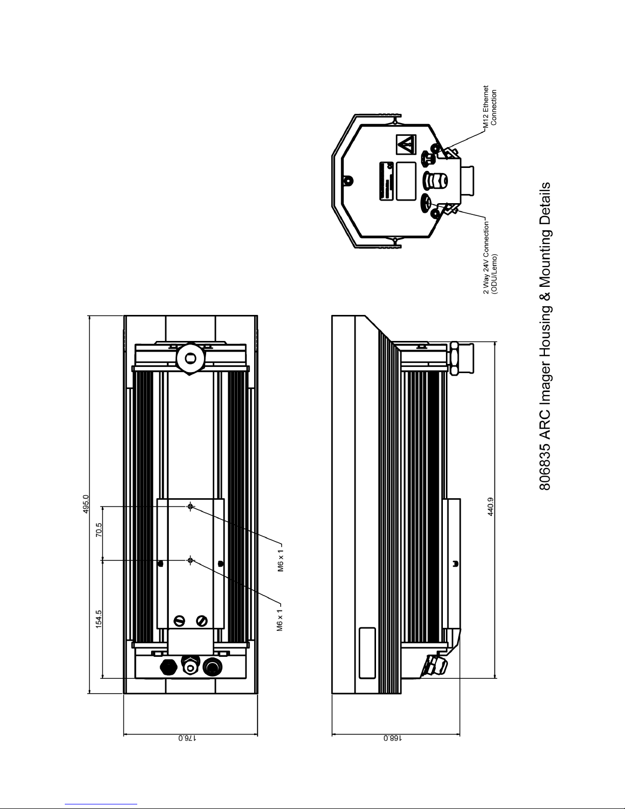
Arc Thermal Imaging CameraInstallation Guide
Page 7
Page 14
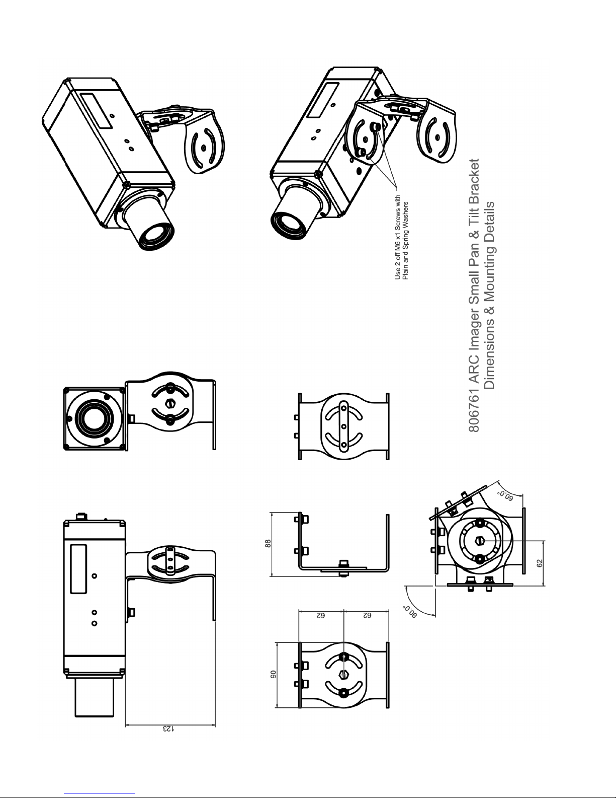
Arc Thermal Imaging Camera Installation Guide
Page 8
Page 15
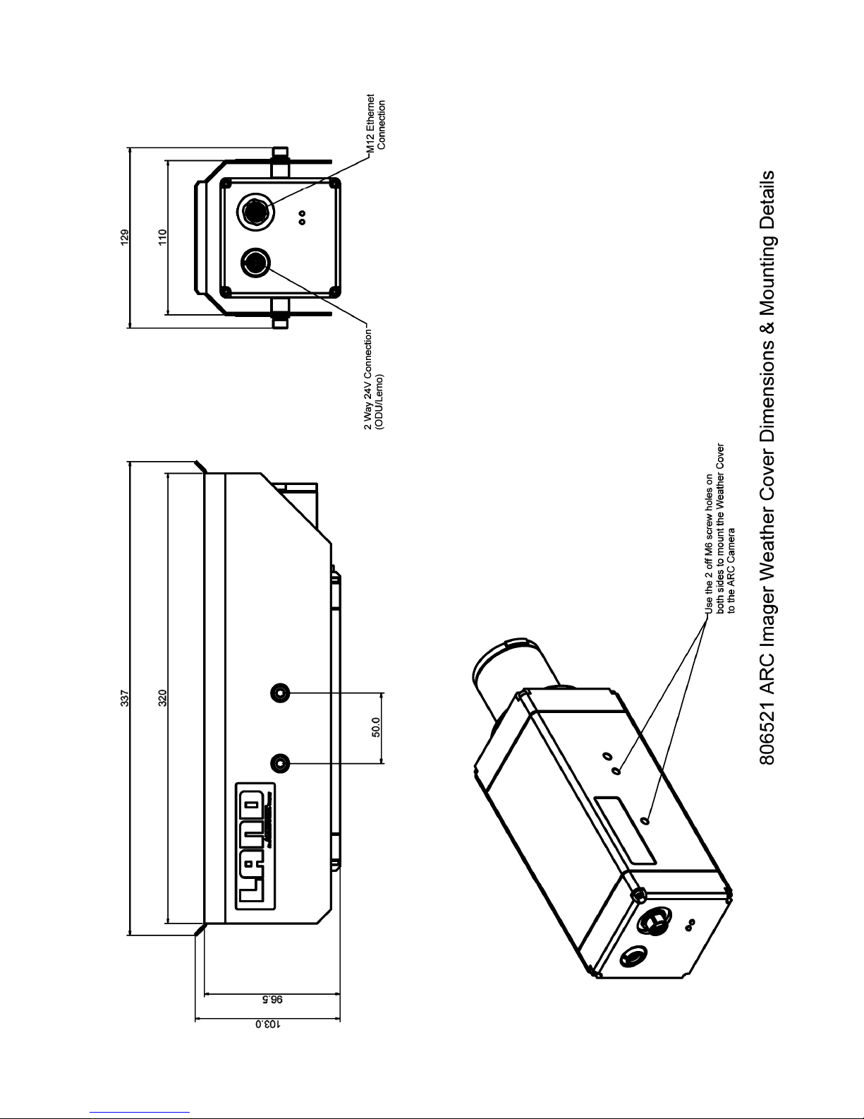
Arc Thermal Imaging CameraInstallation Guide
Page 9
Page 16

Arc Thermal Imaging Camera Installation Guide
Page 10
Page 17

PRODUCT WARRANTY
Thank you for purchasing your new product from Land Instruments International. This Land
manufacturer’s ‘back-to-base’ warranty covers product malfunctions arising from defects in design
or manufacture. The warranty period commences on the instrument despatch date from the Land
Instruments International Ltd. factory in Droneld, UK.
36 MONTHS WARRANTY
Building upon the reputation for reliability and longevity that System 4 and UNO thermometers
have earned, Land are delighted to be able to provide our customers with an industry-leading
36 month warranty for the following products:-
• System 4 thermometers, processors, accessories and mountings and special instruments
based on System 4.
• UNO thermometers, accessories and mountings and special instruments based on UNO.
• Application-dedicated processors based on LANDMARK
®
Graphic.
• ABTS/S and ABTS/U.
• FTS.
• VDT/S and VDT/U.
• DTT.
• FLT5/A.
This 36 month warranty is provided as standard for all orders for the products listed above received from
1st May 2002.
We believe that our customers expect us to set the standard in terms of performance, quality, reliability and
value for money. This 36 months warranty, as a part of an on-going program of continuous improvement,
is just one way in which Land strive to maintain our position as the temperature measurement partner of
choice.
24 MONTHS WARRANTY
The following Land Instruments International products are provided with a 24 months warranty:
• ARC.
• FTI-E.
12 MONTHS WARRANTY
All Land Instruments International products not provided with either a 36 month or 24 month warranty (see
lists above), are provided with a 12 months warranty.
Page 18

PRODUCT WARRANTY
EXCLUSIONS FROM WARRANTY
It should be noted that costs associated with calibration checks which may be requested during the warranty
period are not covered within the warranty.
Land reserve the right to charge for service/calibration checks undertaken during the warranty period if the
cause is deemed to fall outside the terms of the warranty.
This Land manufacturer’s warranty does not cover product malfunction arising from:-
• incorrect electrical wiring.
• connection to electrical power sources outside the rating of the product.
• physical shock (being dropped, etc.) and impact damage.
• inappropriate routing, support, physical shock & strain protection, etc. of the lightguide (Fibroptic
thermometers only).
• environmental conditions exceeding the IP / NEMA rating of the product.
• environmental conditions outside the Ambient Temperature, Humidity and Vibration rating of the product.
• environmental contamination (solvent vapours, deposition of airborne contamination, cooling liquids of
non-neutral pH, etc.).
• overheating as a result of interruption of water/air ow through cooling jackets or of incorrect installation.
• inappropriate modication of product (drilling holes in thermometer bodies, etc.).
• inappropriate recalibration which results in product calibration being taken outside specication.
• improper resealing of thermometer following parameter adjustment (UNO, FLT5/A, etc.).
• attempted repair by a non-Land-authorised repair centre.
Land I nstr ument s In tern ation al L td • Dro nfie ld S1 8 1D J • E ngla nd • Te l: +4 4 (0 ) 12 46 417 691 • Fa x: + 44 (0) 124 6 410 585
Email: [email protected] • www.landinst.com
AM ET E K La nd , I nc . • 1 50 Fr e e po rt R d . • Pi t ts bu r g h, PA 15 23 8 • U. S. A . • Tel : + 1 ( 41 2 ) 82 6 4 4 4 4
Email: [email protected] • www.ametek-land.com
For a complete list of our international offices, please visit www.landinst.com
04/11
 Loading...