

Page 1
UNDER THE COUNTER BEER DISPENSER
Operation Manual
PN: 28-0915/01
Technical Support/Warranty: 800-729-1550
“Lancer” is the registered trademark of Lancer © 2014 by Lancer, all rights reserved.
Lancer Corp.
6655 Lancer Blvd.
San Antonio, Texas 78219
800-729-1500
custserv@lancercorp.com
lancercorp.com
Manual PN: 28-0915/01
JUNE 2013
FOR QUALIFIED INSTALLER ONLY
Page 2

ABOUT THIS MANUAL
This booklet is an integral and essential part of the product and should be handed over to the operator after the
installation and preserved for any further consultation that may be necessary. Please read carefully the guidelines and
warnings contained herein as they are intended to provide the user with essential information for the continued safe
use and maintenance of the product. In addition, it provides GUIDANCE ONLY to the user on the correct services and
site location of the unit.
The installation and relocation, if necessary, of this product must be carried out by qualied personnel with up-to-date
safety and hygiene knowledge and practical experience, in accordance with current regulations.
TABLE OF CONTENTS
SPECIFICATIONS................................................................................................................................4
PRE-INTALLATION CHECKLIST........................................................................................................5
WARNINGS/CAUTIONS...................................................................................................................6-8
1. INSTALLATION.............................................................................................................................8
1.1 UNPACKING......................................................................................................................8-9
1.2 SELECTING A LOCATION....................................................................................................9
1.3 ASSEMBLING THE UNIT.....................................................................................................9
1.4 CONNECTING TO ELECTRICAL POWER........................................................................10
1.5 CONNECTING THE DRAIN...............................................................................................10
1.6 EQUIPMENT SETUP..........................................................................................................10
2. GETTING STARTED...................................................................................................................10
2.1 SETTING AND ADJUSTING THE AIR PRESSURE REGULATOR...............................10-11
2.2 CONNECTING THE KEGS............................................................................................11-12
2.3 DISCONNECTING THE KEGS..........................................................................................13
2.4 CONNECTING A NEW KEG...............................................................................................13
2.5 KEG USE AND STORAGE CAUTION................................................................................14
3. BEER DISPENSE........................................................................................................................14
3.1 POURING RITUAL - STELLA ARTOIS...............................................................................14
3.2 POURING OTHER BEERS................................................................................................15
4. CLEANING AND SANITIZING.....................................................................................................15
4.1 GENERAL INFORMATION.................................................................................................15
4.2 CLEANING AND SANITIZING SOLUTIONS.................................................................15-16
4.3 DAILY CLEANING..............................................................................................................16
4.4 MONTHLY MAINTENANCE AND CLEANING...............................................................16-17
4.5 SIX WEEKS PREVENTATIVE MAINTENANCE.................................................................17
5. TROUBLESHOOTING GUIDE FOR END USER..................................................................17-19
5.1 TOO MUCH FOAM WHEN BEER DISPENSED.................................................................17
5.2 FIRST GLASS HAS A LOT OF FOAM................................................................................18
5.3 NOT ENOUGH FOAM........................................................................................................18
5.4 PRODUCT JETS OUT FROM THE SPOUT.......................................................................18
5.5 CANNOT LOCK THE FRONT DOOR OF THE CABINET..................................................18
5.6 BEER LEAKS.....................................................................................................................18
5.7 WARM BEER......................................................................................................................19
5.8 VERY LOW OR NO BEER FLOW......................................................................................19
5.9 UNIT MAKES BUZZING NOISE.........................................................................................19
5.10 UNIT DOES NOT MOVE EASILY.......................................................................................19
2
Page 3

6. TROUBLESHOOTING GUIDE FOR TECHNICIANS............................................................20-22
6.1 AIR COMPRESSOR DOES NOT START...........................................................................20
6.2 AIR COMPRESSOR IS NOT PROVIDING ENOUGH AIR FLOW......................................20
6.3 AIR COMPRESSOR TANK DOES NOT REACH A PRESSURE OF 101 PSI....................20
6.4 MISCELLANEOUS LEAKAGE OF COMPRESSED AIR....................................................20
6.5 REFRIGERATION COMPRESSOR DOES NOT TURN ON, OR STOPS RUNNING........21
6.6 CONDENSER FAN DOES NOT TURN ON, OR STOPS RUNNING..................................21
6.7 EXCESSIVE ICE BUILD UP AROUND EVAPORATOR AREA..........................................21
6.8 REFRIGERATION COMPRESSOR DOES NOT STOP.....................................................21
6.9 COMPRESSOR CYCLES ON AND OFF............................................................................21
6.10 CIRCUIT BREAKER TRIPPING.........................................................................................22
6.11 EXCESSIVE CONDENSATION APPEARS AROUND THE DOOR....................................22
6.12 DEFROST CYCLE SEEMS TO BE TOO LONG FOR THE 115V MACHINE.....................22
6.13 CONDENSER FAN DOES NOT SHUT OFF.......................................................................22
6.14 PRESSURE REGULATOR IS MALFUNCTIONING............................................................22
6.15 UNIT IS IN STANDBY MODE.............................................................................................22
7. PROGRAMMING THE COOLING PARAMETERS - 115 VOLT MODEL...................................22
7.1 ADJUSTING THE TEMPERATURE SET POINT................................................................22
7.2 ADJUSTING THE REFRIGERATION COMPRESSOR RELAY
TRIPPING DIFFERENTIAL................................................................................................23
7.3 ADJUSTING THE DEFROST ENDURANCE TIME............................................................23
7.4 ADJUSTING THE TIME INTERVAL BETWEEN DEFROSTING CYCLES.........................23
7.5 CHANGING THE CONTROLLER FROM FAHRENHEIT TO CELCIUS.............................23
8. PROGRAMMING THE COOLING PARAMETERS - 230 VOLT MODEL...................................24
8.1 ADJUSTING THE TEMPERATURE POINT........................................................................24
8.2 ADJUSTING THE REFRIGERATION COMPRESSOR RELAY
TRIPPING DIFFERENTIAL.................................................................................................24
9. DISPENSER DISPOSAL.............................................................................................................24
10. ILLUSTRATIONS, PART LISTINGS, AND WIRING DIAGRAMS...............................................25
10.1 WIRING DIAGRAM.............................................................................................................25
10.2 EXPLODED VIEW.........................................................................................................26-27
3
Page 4
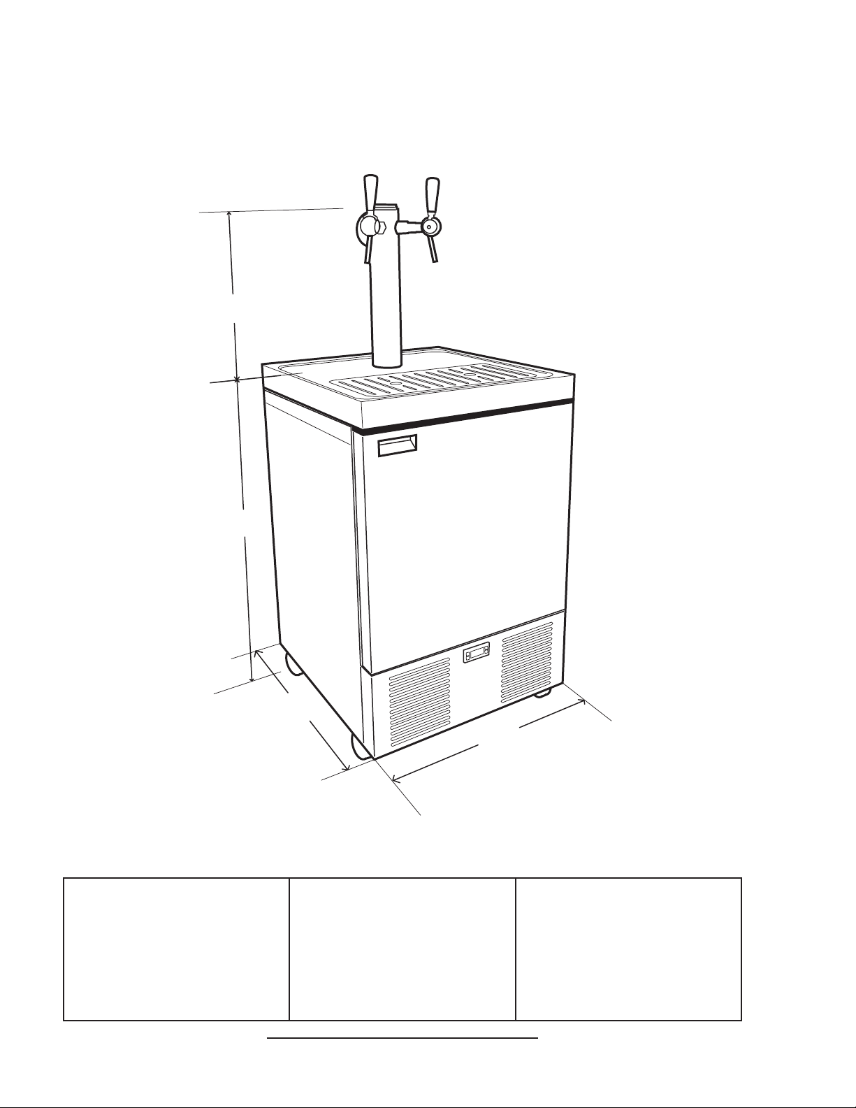
UTC BEER DISPENSER SPECIFICATIONS
39.88
(1,013)
23.60
(599.44)
25.70
(652.80)
17.25
(438.2)
32°F
DIMENSIONS
Width: 23.6 inches (599.4 mm)
Depth: 25.7 inches (652.8 mm)
Height: 57.13 inches (1451.5 mm)
Tower Height: 17.25 inches
(438.2 mm)
SPACE REQUIRED
Left Side: 1 inch (25.4 mm)
Right side: 1 inch (25.4 mm)
Back: 1 inch (25.4 mm)
Casters: 4 inches (101.6 mm)
ELECTRICAL
115 VAC/ 60 Hz / 9 Amps
230 VAC/ 50 Hz / 4.5 Amps
WEIGHT
Shipping: 227 lbs (103 kg)
Installed: 197 lbs (89.36 kg)
This unit emits a sound pressure level below 70 dB
4
Page 5
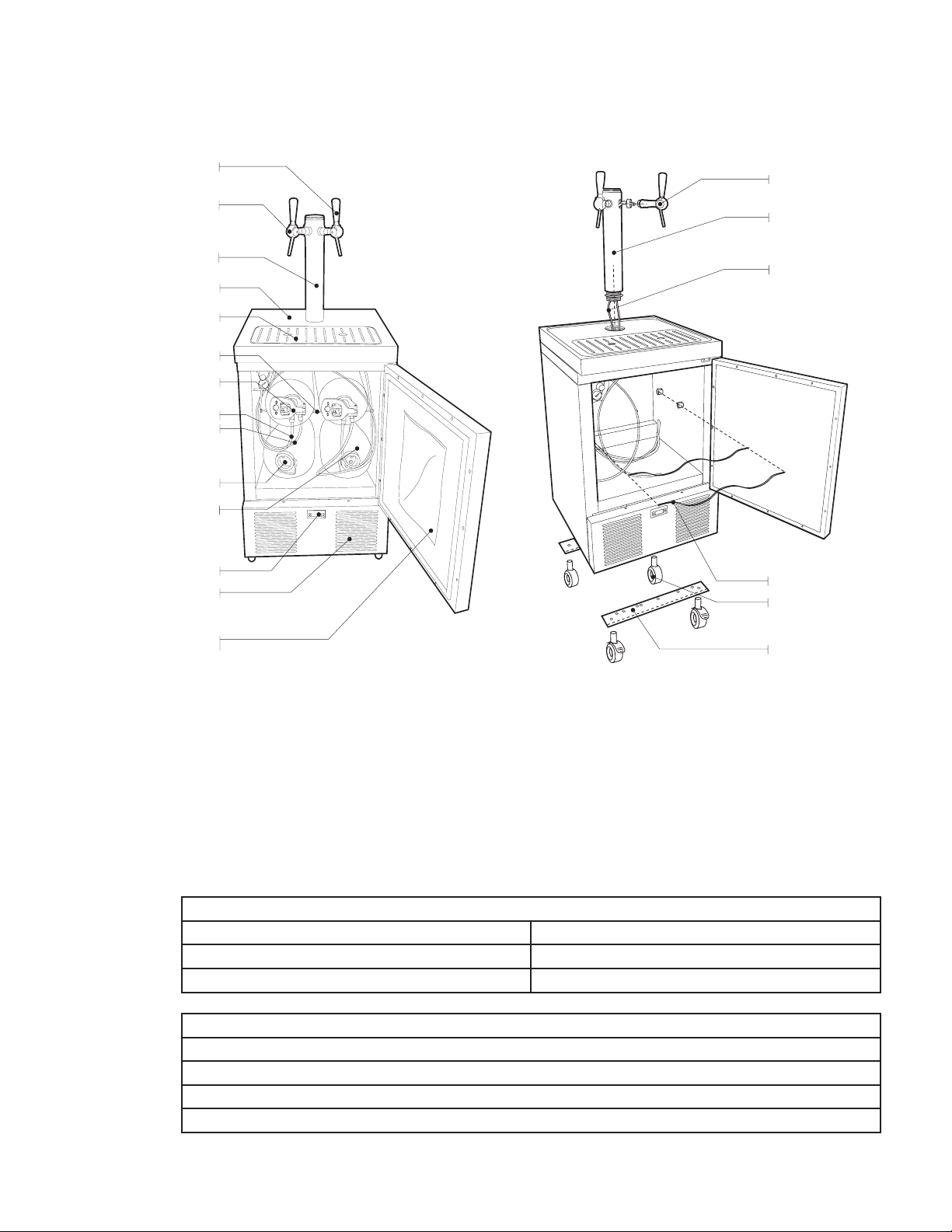
ABOUT THIS DISPENSER
AIR FILTER
TEMPERATURE CONTROL
KEG
KEG CLOSURE
AIR LINE
BEER TUBING
KEG CONNECTOR
RACK
CUP REST
STAGE
TOWER
TAP
TAP HANDLE
CABINET DOOR WITH
USAGE INSTRUCTIONS
BEER TUBING
KEG RACKS
CASTERS
SUPPORT
TOWER
TAP
The dispenser has its own cooling and air compression system and can house up to 4 kegs
of product. Only the top two kegs can be connected to the tower, and up to two taps can be
used on this dispensing unit (two taps mounted on 1 tower).
PRE-INSTALLATION CHECKLIST
BEFORE GETTING STARTED
Each unit is tested under operating conditions and is thoroughly inspected before
shipment. At the time of shipment, the carrier accepts responsibility for the unit. Upon
receiving the unit, carefully inspect the carton for visible damage. If damage exists, have
the carrier note the damage on the freight bill and le a claim with carrier. Responsibility for
damage to the dispenser lies with the carrier.
Beer Keg Racks (2) Keg Containers (2)
Tower Taps (2)
Tap handles (2) Casters (2 with brakes, 2 without brakes)
Drain
Grounded electrical outlet.
Heating and air conditioning ducts
Enough space to install the dispenser. A minimum of 1 inch on all sides is required.
ACCESSORIES
CONSIDER LOCATION OF THE FOLLOWING PRIOR TO INSTALL
5
Page 6

! !
WARNING/ADVERTENCIA/AVERTISSEMENT
! Respect the basic safety instructions given by the manufacturer. Take care of your personal safety. Dispenser is designed for
cooling and dispensing beer. The supplier shall not be liable for damages caused by improper use. This unit is not designed to
dispense dairy products. This appliance is intended to be used in commercial applications such as restaurants or similar. The
dispenser is only to be used in combination with the provided kegs. Do not use any other commercially available beer kegs. This
dispenser is for indoor use only. This unit is not a toy. Children should be supervised to not play with the appliance. It should not be
used by children or inrm persons without supervision. This dispenser is not intended for use by persons (including children) with
reduced physical, sensory or mental capabilities, or lack of experience and knowledge, unless they have been given supervision or
instruction concerning use of the dispenser by a person responsible for their safety. Cleaning and user maintenance shall not be
performed by children without supervision. This unit is not suitable for installation in an area where a waterjet could be used. The
min/max ambient operating temperature for the dispenser is 40°F (4.4°C) to 86°F (30°C). Do not place unit on its side even during
transportation. Do not leave the cabinet door open longer than necessary while the dispenser is connected. Do not block the air inlet
of the dispenser (bottom panels). Keep enough free space around the dispenser according to the specications in this manual. Do
not tamper with the temperature control. Do not operate this dispenser when parts are missing or broken. Make sure all parts of the
dispenser are properly assembled before usage. Always use original parts the manufacturer or supplier does not take any
responsibility for parts which are not original or recommended by the manufacturer. The bottom panels (front and rear) of the
dispenser should only be opened by trained personnel. If not trained, opening the panels will be at the user’s own risk. To avoid
personal injury or damage, do not attempt to lift a unit without helpfor heavier units, use of a mechanical lift may be appropriate.
Always wear protective shoewear during installation.
! Respete las instrucciones básicas de seguridad indicadas por el fabricante. Cuide su seguridad personal. El dispensador está
diseñado para el enfriamiento y la dispensación de cerveza. El proveedor no será responsable por los daños causados por uso
inadecuado. Esta unidad no ha sido diseñada para suministrar productos lácteos. Esta unidad está diseñada para su uso en
aplicaciones comerciales tales como restaurantes, tienda o similares. El dispensador sólo debe ser utilizado en combinación con
los barriles suministrados. No utilice ningún otro barril de cerveza disponible comercialmente. El dispensador sólo debe usarse en
interiores. Esta unidad no es un juguete. Los niños deben ser supervisados para no jugar con aparato. No la deben usar niños ni
personas discapacitadas sin supervisión. Esta unidad no está destinada al uso por parte de personas (incluso niños) con capacidad
física, sensorial o mental reducida, o sin experiencia y conocimientos sucientes, a menos que una persona responsable de su
seguridad les haya dado supervisión o capacitación en el uso de la unidad. Limpieza y mantenimiento de usuario no deberá ser
realizada por los niños sin supervisión. Esta unidad no es adecuada para su instalación en un área donde podría utilizarse un
chorro de agua. La temperatura ambiente operativa mínima / máxima para el dispensador es de 40°F a 86°F (4.4°C a 30°C). No
coloque la unidad de lado incluso durante el transporte. No deje la puerta del armario abierta más tiempo del necesario mientras el
dispensador. Está conectado no obstruya la entrada de aire del dispensador (paneles de fondo). Mantenga suciente espacio libre
alrededor del distribuidor según las especicaciones de este manual. No manipule el control de temperatura. No opere este
dispensador cuando falten partes o haya partes rotas. Asegúrese de que todas las partes del dispensador estén montadas
correctamente antes de su uso. Siempre utilice piezas originales: el fabricante o el proveedor no asumen ninguna responsabilidad
por partes que no sean originales o recomendadas por el fabricante. Los paneles inferiores (delanteros y traseros) del dispensador
sólo deben ser abiertos por personal capacitado. Si no está entrenado, abrir los paneles será al riesgo del usuario. Evite las
lesiones personales, no trate de levantar el dispensador sin ayuda. Para los dispensadores màs pesados use un elevador
mecánico. Siempre use calzado protector durante la instalación.
! Respectez les consignes de securite de base fournies par le fabricant. Prenez soin de votre sécurité personnelle. Le distributeur
est conçu pour le refroidissement et la distribution de bière. Le fournisseur ne pourra pas être tenu responsable des dommages
causés par une mauvaise utilisation. Cet appareil n’est pas conçu pour distribuer des produits laitiers. Cet appareil est conçu pour
une utilisation dans des applications commerciales telles que les restaurants, les dépanneurs ou similaires. Le distributeur ne doit
être utilisé qu’en combinaison avec les fûts fournis. Ne pas utiliser d’autres fûts de bière disponibles sur le marché. Cet appareil
n’est pas un jouet. Les enfants doivent être surveillés an de ne pas jouer avec l’appareil. Il ne devrait pas être utilisé par des
enfants ou des personnes inrmes sans surveillance. Cet appareil n’est pas destiné à un usage par des personnes (y compris les
Enfants) ayant des capacités physiques, sensorielles ou mentales réduites, ou manquant d’expérience et de Connaissances, à
moins qu’elles obtiennent de la surveillance ou des instructions au sujet de l’utilisation de l’appareil de la part d’une personne
chargée de leur sécurité. Nettoyage et entretien de l’utilisateur ne doivent pas être effectués par des enfants sans surveillance. Cet
appareil n’est pas approprié pour une installation dans une zone où un jet d’eau pourrait être utilisé. La température de service
ambiante minimum/maximum pour le distributeur est de 40°F à 86°F (4.4°C à 30°C). Ne pas placer l’unité sur le coté, même durant
le transport. Ne laissez pas la porte du meuble ouverte plus longtemps que nécessaire lorsque le distributeur est relié. Ne bloquez
pas l’entrée d’air du distributeur (panneaux du bas). Gardez assez d’espace libre autour du distributeur en accord avec les
spécications dans ce manuel. Ne pas jouer avec le controle de la température. Ne pas utiliser ce distributeur lorsque des pièces
sont manquantes ou endommagées. Assurez-vous que toutes les pièces du distributeur sont assemblées correctement avant
l’utilisation. Utilisez toujours des pièces d’origine le manufacturier ou le fournisseur ne prend aucune responsabilité pour les
pièces qui ne sont pas d’origine ou recommandées par le manufacturier. Les panneaux du bas (avant et arrière) du distributeur ne
devraient être ouverts que par du personnel qualié. Si non qualié, l’ouverture des panneaux se fait aux risques de l’utilisateur.
Pour éviter des blessures ou des dommages, n’essayez pas de soulever une unité sans aide. Pour les unités plus lourdes,
l’utilisation d’un ascenseur mécanique peut être appropriée. Portez toujours des chaussures de protection pendant l’installation.
6
Page 7

PRESSURE WARNING/ ADVERTENCIA DE PRESIÓN/
! !
AVERTISSEMENT DE PRESSION
! This dispenser contains pressurized components. Only use these components according to the instructions in this
manual. Failure to follow the instructions can result in Serious injury and equipment damage. The allowable pressure
ranges between 18 psi (0.124 Mpa) and 24 psi (0.165 Mpa). It is recommended to set the pressure within the
allowable range to obtain proper beer dispensing. Do not tamper with the pressure regulator control. Do not use any
other external pressure source. Do not connect provided keg to any other external pressure source. The bottom
panels (front and rear) of the dispenser should only be opened by trained personnel. If not trained, opening the
panels will be at the user’s own risk. Do not store explosive substances such as aerosol cans with aammable
propellant in the dispenser.
! Este dispensador contiene componentes presurizados. Sólo utilice estos componentes según las instrucciones en
este manual. No seguir las instrucciones puede causar lesiones graves y daño al equipo. Las gamas de presión
permitidas son entre 18 PSI (0.124 MPA) y 24 PSI (0.165 MPA). Se recomienda ajustar la presión dentro del rango
permitido para obtener la dispensación correcta de la cerveza. No manipule el control del regulador de presión. No
utilice ninguna otra fuente de presión externa. No conecte el barril proporcionado a cualquier otra fuente de presión
externa. Los paneles inferiores (delanteros y traseros) del dispensador sólo deben ser abiertos por personal
capacitado. Si no está entrenado, abrir los paneles será al riesgo del usuario. No almacene sustancias explosivas
como latas de aerosol con un propulsor inamable en el dispensador.
! Ce distributeur contient des composantes pressurisées. N’utilisez ces composantes qu’en accord avec les
instructions dans ce manuel. Le non-respect des instructions peut résulter dans de graves blessures et des
dommages à l’équipement. La pression admissible est comprise entre 18 PSI (0.124 MPA) et 24 PSI (0.165 MPA).
Il est recommandé de régler la pression à l’intérieur de la plage admissible pour obtenir une distribution de bière
adéquate. Ne pas jouer avec le contrôle de régulation de pression. N’utilisez pas aucune autre source de pression
externe. Ne reliez pas le fût fournis à aucune autre source de pression externe. Les panneaux du bas (avant et
arrière) du distributeur ne devraient être ouverts que par du personnel qualié. Si non qualié, l’ouverture des
panneaux se fait aux risques de l’utilisateur. N’entreposez pas de substances explosives telles que des bonbonnes
d’aérosols avec des agents propulseurs inammables dans le distributeur
7
Page 8

ELECTRICAL WARNING/ADVERTENCIA ELÉCTRICA/
F F
AVERTISSEMENT ÉLECTRIQUE
! Check the dispenser serial number plate for correct electrical requirements. Do not plug into a wall electrical outlet
unless the current shown on the serial number plate agrees with local current. Follow all local electrical codes when
making connections. Make sure that all lines and tubing are tight and units are dry before making any electrical
connections. Keep the dispenser plugged in at all times, unless stated otherwise in the instructions. Each dispenser
must have a separate electrical circuit. Do not connect multiple. Electrical devices on the same outlet. Do not use
extension cords with this unit. The dispenser must be properly electrically grounded to avoid serious injury or fatal
electrical shock. The power cord has a three-prong grounded plug. If a three-hole grounded electrical outlet is not
available, use an approved method to ground the unit. Follow all local electrical codes when making connections. If
the supply cord is damaged, it must be replaced by the manufacturer, an authorized service agent or similarly
qualied person to avoid hazard or injury. Never touch electrical components with wet or damp hands. Always
disconnect electrical power to the unit to prevent personal injury before attempting any internal maintenance. Only
trained personnel should service internal components.
! Verique la placa con el número de serie del dispensador, donde encontrará los requisitos eléctricos correctos
de la unidad. No enchufe la unidad en un tomacorriente de pared a menos que la corriente indicada en la placa con
el número de serie concuerde con la corriente local disponible. Al hacer las conexiones, respete todos los códigos
eléctricos locales. Asegúrese de que todas las líneas de agua estén ajustadas y las unidades estén secas antes de
hacer conexiones eléctricas. Mantenga el dispensador conectado en todo momento a menos que las instrucciones
indiquen lo contrario. Cada dispensador debe tener un circuito eléctrico independiente. No use extensiones con esta
unidad. Es necesario poner a tierra eléctricamente el dispensador para evitar lesiones graves e incluso
electrochoques fatales. El cable de alimentación tiene un enchufe puesto a tierra de 3 clavijas. Si no se dispone
de un toma eléctrico conectado a tierra de tres agujeros, use un método aprobado para poner a tierra la unidad. Al
hacer las conexiones, respete todos los códigos eléctricos locales. Si el cable de alimentación está dañado, debe ser
reemplazado por el fabricante, un agente de servicio autorizado o una persona cualicada para evitar peligros o
lesiones. Nunca toque los componentes eléctricos con las manos mojadas o húmedas. Siempre desconecte la
alimentación eléctrica a la unidad para evitar lesiones personales antes de tratar de realizar tareas de
mantenimiento. El servicio de los componentes internos de la caja de control eléctrico debe conarse exclusivamente
a personal calicado.
F Examinez la plaque de numéro de série du distributeur pour connaître les bonnes exigences en matière
d’électricité pour l’appareil. Ne le branchez pas à une prise électrique murale à moins que le courant indiqué sur la
plaque de numéro de série corresponde au courant local disponible. Respectez tous les codes électriques locaux
lorsque vous faites des connexions. Assurez-vous que toutes les conduites d’eau sont étanches et que les
appareils sont secs avant de faire des connexions électriques. Gardez le distributeur branché en tout temps, sauf si
mentionné autrement dans les instructions. Chaque distributrice doit avoir un circuit électrique séparé. N’utilisez
pas de cordons prolongateurs avec cet appareil. La distributrice doit être mise à la terre électriquement correctement
pour éviter des blessures graves ou une décharge électrique mortelle. Le cordon d’alimentation a une che à trois
branches mise à la terre. Si aucune prise de courant électrique à trois trous n’est disponible, utilisez une méthode
approuvée pour mettre l’unité à la terre. Respectez tous les codes électriques locaux lorsque vous faites des
connexions. Si le cordon d’alimentation est endommagé, il doit être remplacé par le manufacturier, ou par un agent
de service autorisé ou autre personne similairement qualiée pour éviter tout risque ou blessure. Ne jamais toucher
à des composantes électriques avec des mains mouillées ou humides. Débranchez toujours le courant électrique à
l’appareil, an de prévenir des blessures, avant de faire un entretien interne quelconque. Seul le personnel qualié
devrait faire l’entretien/la réparation des composants internes dans le logement des commandes électriques.
Page 9

KEG WARNING/ ADVERTENCIA DEL BARRIL/
! !
AVERTISSEMENT FÛT
! Always read and follow the instructions and safety warnings on the keg before connecting to the dispenser. Never
store a keg in the freezer! Freezing may cause serious damage to the keg. Do not store the lled kegs at
temperatures higher than 86°F (30°C). Maximum working pressure: 24 PSI (0.165 MPA). Do not overpressurize the
keg. This may cause injury. Do not use pressurized co2 on the kegs. Always handle kegs with care. Do not shake the
keg. Do not drop the keg. Be careful with condensation droplets that will make the keg slippery in your hands. For
the integrity of the dispenser, do not place damaged kegs in it. Do not pierce a connected keg. Do not burn a keg,
even when empty. For storage purposes outside the dispenser: make sure the kegs are stacked in a safe way. Store
a connected keg using the racks in the dispenser. Make sure the dispenser is switched on at all times, unless stated
otherwise in the instructions. If dispenser is switched off due to non use for a long period (e.G. A holiday), always
remove the connected keg from the dispenser and dispose of it. Once a keg has been connected, the beer stays
fresh for 30 days.
! Siempre lea y siga las instrucciones y advertencias de seguridad sobre el barril antes de conectar el dispensador.
Nunca guarde un barril de cerveza en el congelador. La congelación puede causal graves daños al barril. No
almacene los barriles llenos a temperaturas superiores a 86° F (30° C). Presión máxima de trabajo: 24 PSI (0.165
MPA). No ponga presión superior en el barril. Esto puede causar lesiones. No use co2 presurizado en los barriles.
Siempre maneje los barriles con cuidado. No agite el barril. No deje caer el barril. Tenga cuidado con las gotas de
condensación que causarán que el barril sea resbaladizo en sus manos. Para la integridad del dispensador, no
coloque barriles dañados en él. No perfore un barril conectado. No queme un barril, incluso cuando esté vacío. Para
nes de almacenamiento fuera del dispensador: asegúrese de que los barriles se apilen en una manera segura.
Guarde un barril conectado usando las parrillas en el dispensador. Asegúrese de que el dispensador está encendido
en todo momento, a menos que se indique lo contrario en las instrucciones. Si el dispensador está desactivado
debido a la falta de uso durante un período prolongado (por ejemplo un día feriado), siempre retire el barril conectado
del dispensador y deséchelo. Una vez que se haya conectado un barril, la cerveza se mantiene fresca por 30 días.
! Lisez et suivez toujours les instructions et les avertissements de sécurité sur le fût avant de le relier au
distributeur. N’entreposez jamais un fût dans le congélateur! Le gel peut causer de sérieux dommages au fût.
N’entrepoesz pas les fûts remplis à des températures plus hautes que 86°F (30°C). Pression maximale de
fonctionnement : 24 PSI (0.165 MPA). N’utilisez pas de pression excessive avec le fût. Ceci pourrait causer des
blessures. Ne pas utiliser de c02 pressurisé sur les fûts. Manipulez toujours les fûts avec soin. Ne pas secouer le fût.
Ne pas laisser tomber le fût. Faites attention avec les goutelettes de condensation qui rendront le fût glissant dans
vos mains. Pour l’intégrité du distributeur, ne placez pas de fûts endommagés à l’intérieur. Ne percez pas un fût relié.
Ne brulez pas un fût, même lorsque vide. Lors de l’entreposage à l’extérieur du distributeur : assurez-vous que les
fûts sont empilés d’une manière sécuritaire. Entreposez les fûts en utilisant les supports fournis dans le distributeur
assurez-vous que le distributeur est allumé en tout temps, sauf si mentionné autrement dans les instructions. Si le
distributeur est éteint à cause d’une non-utilisation pendant une longue période (par exemple un congé), reitrez
toujours le fût reliédu distributeur et disposez-en. Une fois qu’un fût est relié, la bière reste fraîche pour 30 jours.
SANITIZING WARNING/ ADVERTENCIA DE
! !
DESINFECCIÓN/ AVERTISSEMENT DÉSINFECTION
! Before maintenance, always disconnect the dispenser from the electricity supply. Ensure sanitizing solution is
removed from the dispenser as instructed. Avoid getting sanitizing solution on circuit boards. Do not use strong
bleaches or detergents; these can discolor and corrode various materials. Do not use metal scrapers, sharp objects,
steel wool, scouring pads, abrasives, or solvents on the dispenser. Do not use hot water above 140°F (60°C). This
can damage the dispenser.
! Asegúrese de haber eliminado la solución de esterilización del dispensador de acuerdo con las instrucciones. Los
residuos de la solución de esterilización representan un peligro para la salud. Evite que la solución de esterilización
llegue a las placas de circuitos. No use lavandinas ni detergentes que podrían quitar el color y corroer distintos
materiales. No use raspadores metálicos, objetos losos, lana de acero, estropajos, abrasivos ni solventes en el
dispensador. No use agua caliente a más de 140 ºF (60 ºC). Podría dañar el dispensador.
! L’eau chaude permettra un meilleur procès de dissolution. Suivant les instructions jointes, il est impératif que la
solution septique soit entièrement enlevée. Evitez de mettre la solution en contact avec les circuits. N’utilisez pas de
javellisants ou dedétergents forts; ceux-ci peuvent décolorer et corroder divers matériaux. N’utilisez pas de
racleurs en métal, d’objets pointus, de laine d’acier, de tampons à récurer, d’abrasifs ou de solvants sur le
distributeur. N’utilisez pas de l’eau chaude de plus de 140 degrés F (60 degrés C). Ceci peut endommager le
distributeur.
Page 10

GOVERNMENT WARNING/ ADVERTENCIA
!
! According to the surgeon general, women should not drink alcoholic beverages during pregnancy because of the
risk of birth defects. Consumption of alcoholic beverages impairs your ability to drive a car or operate machinery, and
may cause health problems
! Según el cirujano general, las mujeres no deben beber bebidas alcohólicas durante el embarazo debido al riesgo
de defectos de nacimiento. El consumo de bebidas alcohólicas deteriora su capacidad para conducir o manejar
maquinaria y puede causar problemas de salud.
! En accord avec le médecin-chef, les femmes ne devraient pas boire de boissons alcoolisées pendant la
grossesse à cause des risques de malformations à la naissance. La consommation de boissons alcoolisés peut nuire
à votre capacité de conduire une voiture ou d’utiliser de la machinerie, et peut causer des problèmes de santé.
! Units equipped with moving fanblades, which can activate unexpectedly. Do not place hands or foreign objects in
or near the recirculation fan or condensor fan unplug the machine before removing the rear panel.
! Unidades equipadas con aspas de ventilador móviles que pueden activarse inesperadamente. No coloque las
manos u objetos extraños en o cerca del ventilador de recirculación o el ventilador del condensador desenchufe la
máquina antes de quitar el panel trasero
! Les unités sont équipées de pales de ventilateurs, qui peuvent s’activer de manière inattendue. Ne placez pas vos
mains ou des objects quelconques dans ou près du ventilateur de recirculation ou du ventilateur de condensation.
Débranchez la machine avant de retirer le panneau arrière
GUBERNAMENTAL/ AVERTISSEMENT GOUVERNEMENTAL
MOVING PARTS WARNING/ ADVERTENCIA DE
PIEZAS MÓVILES/ AVERTISSEMENT PIÈCES MOBILES
!
SHARP EDGES WARNING/ ADVERTENCIA DE BORDES
!
! Cautious handling is required during moving of the unit, maintenance and operation. Always handle unit with care
to avoid pinching hazard (e.G., During connection of a keg, closing of the cabinet door at door hinges. Use caution
as the unit has sharp edges at the different subparts of the dispenser, including the cup rest, bottom edges, vent slats
and corners.
! La unidad debe manejarse cuidadosamente al moverla, llevar a cabo mantenimiento y operación. Siempre
maneje la unidad con cuidado para evitar peligro de pellizcos (durante la conexión de un barril, cerrando la puerta del
armario (bisagras). Tenga cuidado ya que la unidad tiene bordes alados en las diferentes subpartes del
dispensador, incluyendo el posavasos, bordes inferiores, listones de ventilación y las esquinas
! Une manipulation prudente est requise lors du déplacement de l’unité, de l’entretien et de l’utilisation. Manipulez
toujours l’unité avec soin pour éviter tout risque de pincement (durant la connection d’un fût, fermeture de la porte du
meuble aux charnières de la porte.) Faites attention car l’unité a des rebords coupants à différentes sous-parties du
distributeur, incluant la coupe de repos, les rebords inférieurs, les lattes de ventilation et les coins.
1. INSTALLATION
BEFORE GETTING STARTED
The unit should always be stored and shipped upright. Do not place the unit on its side. If for some
reasonthe unit is placed on its side, allow the refrigerated cabinet to stand in upright position for a
minimum of 8 hours before connecting the power to allow the refrigerant to stabilize before unit activation.
WARNING TO AVOID PERSONAL INJURY OR DAMAGE, DO NOT ATTEMPT TO LIFT A UNIT WITHOUT ASSISTANCE
FOR HEAVIER UNITS, USE OF A MECHANICAL LIFT MAY BE APPROPRIATE. ALWAYS WEAR PROTECTIVE
SHOEWEAR DURING INSTALLATION.
FILOSOS/ AVERTISSEMENT REBORDS COUPANTS
!
!
ADVERTENCIA EVITE LAS LESIONES PERSONALES, NO TRATE DE LEVANTAR EL DISPENSADOR SIN AYUDA.
PARA LOS DISPENSADORES MÀS PESADOS USE UN ELEVADOR MECÁNICO. SIEMPRE USE CALZADO
PROTECTOR DURANTE LA INSTALACIÓN.
AVERTISSEMENT POUR ÉVITER DES BLESSURES OU DES DOMMAGES, N’ESSAYEZ PAS DE SOULEVER UNE
UNITÉ SANS AIDE. POUR LES UNITÉS PLUS LOURDES, L’UTILISATION D’UN ASCENSEUR MÉCANIQUE PEUT
ÊTRE APPROPRIÉE. PORTEZ TOUJOURS DES CHAUSSURES DE PROTECTION PENDANT L’INSTALLATION.
8
Page 11

1.1 UNPACKING
A. Cut banding and remove.
B. Remove top portion of carton by lifting up.
C. Remove accessory kit and loose parts from inside of the cabinet.
D. Remove side inserts
E. Lift unit up by plywood shipping base and remove lower portion of carton.
F. Inspect unit for concealed damage and if evident notify delivering carrier and le a claim.
G. Remove plywood shipping base from unit by moving unit to allow access to screws on the
bottom of the plywood shipping base.
H. Remove and replace the screws with the casters. Install the casters with brakes on the front of
the unit.
NOTE: Leave the unit secured to the plywood base when transporting.
I. When installing the casters on the dispenser, tilt the dispenser. DO NOT PLACE UNIT ON
SIDE OR BACK.
1.2 SELECTING A LOCATION
A. The dispenser is intended for indoor use. Do not store the dispenser outside
B. Select a location close to a properly grounded electrical outlet and to a drain or bucket that
meets the requirements on pages 4 and 5.
C. The selected location must allow the unit to be leveled on all sides.
D. The dispenser may be susceptible to EMC electrical interference. If this occurs, relocate the
dispenser to an alternative location. If interference is still present, contact Lancer Technical
Support.
1.3 ASSEMBLING THE UNIT
A. To assemble the tower, mount the 2 taps on the column.
B. Unscrew the nut from the shank.
C. Insert the shank, with the beer tubing, through the cabinet.
D. Check that the shank is the correct length. If not, tighten (screw) the shank until it is the correct
length. Verify there is enough space for the nut.
E. Tighten the nut over the shank from the inside of the cabinet. Make sure the connection is tight.
If the connection is not tight enough, tighten the nut until the tower does not rotate.
F. Verify the tap handles are in the closed upright position.
NOTE: Unlock the casters to roll the dispenser into its location. Use caution when rolling the
dispenser over rough surface.
A
D
B
E
C
F
9
Page 12

1.4 CONNECTING TO ELECTRICAL POWER
WARNING CHECK THE DISPENSER SERIAL NUMBER PLATE FOR CORRECT ELECTRICAL REQUIREMENTS. DO
NOT PLUG INTO A WALL ELECTRICAL OUTLET UNLESS THE SERIAL NUMBER PLATE VOLTAGE SHOWN AGREES
WITH LOCAL CURRENT. KEEP THE DISPENSER PLUGGED IN AT ALL TIMES, UNLESS STATED OTHERWISE IN
THE INSTRUCTIONS.
ADVERTENCIA VERIFIQUE LA PLACA DE NÚMERO DE SERIE DEL DISPENSADOR PARA OBTENER LOS
REQUISITOS ELÉCTRICOS CORRECTOS. NO ENCHUFE A UN TOMACORRIENTE A MENOS QUE EL VOLTAJE DE
LA PLACA DE NÚMERO DE SERIE QUE SE MUESTRA ACEPTE LA CORRIENTE LOCAL. MANTENGA EL
F
Route the power supply cord to a grounded electrical outlet of the proper voltage and amperage
rating, and plug in the unit. This will turn on the refrigeration system and allow it to start cooling
DISPENSADOR CONECTADO EN TODO MOMENTO, A MENOS QUE LAS INSTRUCCIONES INDIQUEN LO
CONTRARIO.
AVERTISSEMENT VÉRIFIEZ LE PANNEAU DU NUMÉRO DE SÉRIE DU DISTRIBITEUR POUR LES EXIGENCES
ÉLECTRIQUES ADÉQUATES. NE BRANCHEZ PAS DANS UNE PRISE DU MUR À MOINS QUE LE PANNEAU DU
NUMÉRO DE SÉRIE CONCORDE AVEC LE COURANT LOCAL. GARDEZ LE DISTRIBUTEUR BRANCHÉ EN TOUT
TEMPS, SAUF SI SPÉCIFIÉ AUTREMENT DANS LES INSTRUCTIONS.
while completing the rest of the installation.
1.5 CONNECTING THE DRAIN
The drain tube is shipped attached to the stage tray and drain tting. Locate the drain tube at the
rear of the unit and route the drain tube to a suitable drain or bucket.
1.6 EQUIPMENT SETUP
A. Insert the (white) air line into the side of the keg connector.
B. Insert the (transparent) beer tubing into the side of the keg connector.
A
B
10
Page 13

2. GETTING STARTED
2.1 SETTING AND ADJUSTING THE AIR PRESSURE REGULATOR
NOTE: The pressure regulator is located inside the cabinet. Target pressure is 21 PSI (0.145 MPA).
The allowable pressure range is 18- 24 PSI (0.124 MPA - 0.165 MPA).
WARNING IT IS RECOMMENDED TO SET THE PRESSURE WITHIN THE ALLOWABLE RANGE TO OBTAIN PROPER
BEER DISPENSING. DO NOT TAMPER WITH THE PRESSURE REGULATOR CONTROL.
ADVERTENCIA SE RECOMIENDA AJUSTAR LA PRESIÓN DENTRO DEL RANGO PERMITIDO PARA OBTENER
DISENSIÓN DE CERVEZA CORRECTA. NO MANIPULE EL CONTROL DEL REGULADOR DE PRESIÓN.
!
A. The pressure regulator is located inside the fridge.
B. Pull knob towards you until it clicks.
C. Rotate knob; clockwise to increase the pressure, counterclockwise to reduce the pressure.
D. Set pressure to the indicated recommended value.
E. Push knob back into place (until it clicks).
AVERTISSEMENT IL EST RECOMMANDÉ DE RÉGLER LA PRESSION À L’INTÉRIEUR DE LA PLAGE ADMISSIBLE
POUR OBTENIR UNE DISTRIBUTION DE BIÈRE ADÉQUATE.NE PAS JOUER AVEC LE CONTRÔLE DE
RÉGULATION DE PRESSION.
A
B
C
D
2.2 CONNECTING THE KEGS
Cool each keg at least 12 hours in advance prior to dispensing.
NOTE: Place connected kegs at the top only. Never place connected kegs at the bottom, as this will
prevent the door from closing properly. This might result in damage to the cabinet door, keg
connector and/or the connected keg.
E
11
Page 14

2.2 CONNECTING THE KEGS (CONTINUED)
WARNING CAUTIOUS HANDLING IS REQUIRED DURING MOVING OF THE UNIT, MAINTENANCE AND
OPERATION. ALWAYS HANDLE UNIT WITH CARE TO AVOID PINCHING HAZARD (DURING CONNECTION OF A
KEG, CLOSING OF THE CABINET DOOR AT DOOR HINGES. USE CAUTION AS THE UNIT HAS SHARP EDGES AT
THE DIFFERENT SUBPARTS OF THE DISPENSER, INCLUDING THE CUP REST, BOTTOM EDGES, VENT SLATS
AND CORNERS.
ADVERTENCIA LA UNIDAD DEBE MANEJARSE CUIDADOSAMENTE AL MOVERLA, LLEVAR A CABO
MANTENIMIENTO Y OPERACIÓN. SIEMPRE MANEJE LA UNIDAD CON CUIDADO PARA EVITAR PELIGRO DE
PELLIZCOS (DURANTE LA CONEXIÓN DE UN BARRIL, CERRANDO LA PUERTA DEL ARMARIO (BISAGRAS).
TENGA CUIDADO YA QUE LA UNIDAD TIENE BORDES AFILADOS EN LAS DIFERENTES SUBPARTES DEL
!
A. Place the keg vertically in front of the unit.
B. Check that the 3 valves are closed.
C. Check that beer needle is centered in the keg connector. Notice position of air needle.
D. Align air and beer needles in the keg connector with the air and beer holes in closure.
E. Place keg connector on keg.
F. Check that both clamps sit under edge of keg.
G. Push handle down until it clicks and locks into position.
H. If you feel an obstruction, do not push hard and verify alignment of air and beer needles.
I. Open the air valve.
DISPENSADOR, INCLUYENDO EL POSAVASOS, BORDES INFERIORES, LISTONES DE VENTILACIÓN Y LAS
ESQUINAS.
AVERTISSEMENT UNE MANIPULATION PRUDENTE EST REQUISE LORS DU DÉPLACEMENT DE L’UNITÉ, DE
L’ENTRETIEN ET L’UTILISATION. MANIPULEZ TOUJOURS L’UNITÉ AVEC SOIN POUR ÉVITER TOUT RISQUE DE
PINCEMENT (DURANT LA CONNECTION D’UN FÛT, FERMETURE DE LA PORTE DU MEUBLE AUX CHARNIÈRES
DE LA PORTE.) FAITES ATTENTION CAR L’UNITÉ A DES REBORDS COUPANTS À DIFFÉRENTES SOUS-PARTIES
DU DISTRIBUTEUR, INCLUANT LA COUPE DE REPOS, LES REBORDS INFÉRIEURS, LES LATTES DE
VENTILATION ET LES COINS.
A
D
B
E
C
F
G H I
12
Page 15

2.2 CONNECTING THE KEGS (CONTINUED)
J. Open the beer valve.
K. Place connected keg on the top rack of the fridge.
L. Start to dispense.
NOTE: First glass might contain more foam.
J
2.3 DISCONNECTING THE KEGS
NOTE: A keg should only be replaced when completely empty. Replacing a keg that is not yet
empty could result in some beer leakage and spillage in and around the dispenser.
A. Place the keg vertically in front of the unit.
B. Close the air valve.
C. Open the release valve - air will be released!
D. Release for at least 30 seconds.
E. Close the beer valve.
F. Pull release slide (1) and lift up handle (2).
G. Close the release valve.
H. Check that the 3 valves are closed.
A
K L
B
C
D
E
G H
F
NOTE: Before disconnecting
the keg connector, make
sure the air has been
released completely through
the release valve. If air is
still present in the keg, beer
can be spilled.
13
Page 16

2.4 CONNECTING A NEW KEG
To connect a new cooled keg, refer to Section 2.2 Connecting the Kegs.
2.5 KEG USE AND STORAGE CAUTION
A. Store a connected keg using the racks in the dispenser.
B. Make sure the dispenser is switched on at all times, unless stated otherwise in the instructions.
C. If dispenser is switched off due to non use for a long period (e.g. holiday), always remove the
connected keg from the dispenser and dispose of it.
D. Once a keg has been connected, the beer stays fresh for 30 days.
E. Make sure the air lines and beer tubing are free and not entangled nor pinched.
F. Never place a connected keg on the bottom row. The door will not close properly. This might
result in damage to the cabinet door, keg connector and/or the connected keg.
G. A keg should only be replaced when completely empty. If beer is still present after 30 days,
empty the keg, then disconnect and replace it.
H. Make sure the dispenser is well cleaned before loading a new keg.
I. Do not reconnect a keg that has been used before. Once a keg is connected, use the keg until
empty. If the keg is disconnected and reconnected later, the beer quality is not
guaranteed anymore.
3. BEER DISPENSE
3.1 POURING RITUAL - STELLA ARTOIS
A. THE PURIFICATION
The trademark Stella Artois chalice is designed to release the beer’s avor and aroma.
Your bartender will always use one, preferably cleaned with a non-fat-based detergent.
It’s then rinsed with cold water, allowing the glass to reach the same temperature as the beer.
B. THE SACRIFICE
Your bartender opens the tap in one swift motion to let the rst burst of foam ow away.
It must never enter the chalice glass, thus ensuring that every drop of Stella Artois is fresh.
C. THE LIQUID ALCHEMY BEGINS
The chalice glass is held at a 45-degree angle. When the beer hits the chalice and begins to
circulate, it creates the ideal proportion of foam relative to liquid.
D. THE HEAD, ALTHOUGH “CROWN” WOULD BE MORE APPROPRIATE
The natural creation of the foam head occurs by straightening and lowering the glass.
This initial foam is important as it prevents the beer from coming into contact with the air and
losing any avor.
E. THE REMOVAL
Your bartender then closes the tap in one quick action and moves the glass away from the font,
to prevent any drops from falling into the glass. These drops come into contact with the air, and
oxidize, making them unworthy of your glass of Stella Artois.
F. THE BEHEADING
While the head is owing over the edge of the glass, your bartender cuts it gently with a knife
on a 45-degree angle. This eliminates the larger bubbles, which burst easily and accelerate
the dissipation of the head.
G. THE JUDGEMENT
The right amount of foam is about two ngers (3cm) thick. The nal head creates a protective
“cap” that keeps your Stella Artois from going stale.
H. THE CLEANSING
Your bartender then rinses the bottom and sides of the glass. This step keeps the outside of the
chalice clean and comfortable to hold.
I. THE BESTOWAL
Finally, your Stella Artois is served to you on a coaster, accompanied by the drip catcher at the
base. Behold the perfect glass of Stella Artois. Cheers to you, and for your patience, a
refreshing reward.
14
Page 17

3.2 POURING OTHER BEERS
A. Use a chilled glass (preferred) or rinse a clean glass in cold, fresh water prior to tapping. This
will help reduce the amount of foam.
B. Hold the glass at a 45-degree angle under the spout. Keep the spout as close as possible to
the inside of the glass. The spout should not touch the glass.
C. Pull the tap handle all the way down in a quick movement.
D. Let the beer ow against the wall of the glass about one (1) inch below the rim of the glass.
E. Gradually straighten and lower the glass when the foam/beer reaches the rim of the glass.
F. When the glass is full, close the tap handle in one quick movement.
4. CLEANING AND SANITIZING
4.1 GENERAL INFORMATION
A. The cleaning and sanitizing procedures provided pertain to the Lancer equipment identied by
this manual. If other equipment is being cleaned, follow the guidelines established by the
manufacturer for that equipment.
B. Lancer equipment (new or reconditioned) is shipped from the factory cleaned and sanitized in
accordance with NSF* guidelines. The equipment must be cleaned and sanitized after
installation is complete. (Sanitization to be completed by the installer/technician). The operator
of the equipment must provide continuous maintenance as required by this manual, state and
local health department guidelines to ensure proper operation and sanitation requirements
are maintained. *NSF refers to the international food safety standards group
C. Cleaning and sanitizing should be accomplished only by trained personnel. Sanitary gloves are
to be used during cleaning and sanitizing operations. Applicable safety precautions must be
observed. Instruction warnings on the product being used must be followed.
D. Other Required Supplies: 1) Clean cloth towels, 2) bucket, and 3) sanitary gloves.
!
WARNING IF A POWDER SANITIZER IS USED, DISSOLVE IT THOROUGHLY WITH HOT WATER PRIOR TO
ADDING TO THE SYRUP SYSTEM. ENSURE SANITIZING SOLUTION IS REMOVED FROM THE DISPENSER AS
INSTRUCTED. AVOID GETTING SANITIZING SOLUTION ON CIRCUIT BOARDS. DO NOT USE STRONG BLEACHES
OR DETERGENTS; THESE CAN DISCOLORAND CORRODE VARIOUS MATERIALS. DO NOT USE METAL
SCRAPERS, SHARP OBJECTS, STEEL WOOL, SCOURING PADS, ABRASIVES, OR SOLVENTS ON THE
DISPENSER. DO NOT USE HOT WATER ABOVE 140° F (60° C). THIS CAN DAMAGE THE DISPENSER.
ADVERTENCIA SI SE USA UN HIGIENIZADOR EN POLVO, DISUÉLVALO BIEN EN AGUA ANTES DE AGREGARLO
AL SISTEMA DE CONCENTRADO. EL USO DE AGUA CALIENTE CONTRIBUYE A DISOLVER LOS HIGIENIZADORES
EN POLVO. ASEGÚRESE DE HABER ELIMINADO LA SOLUCIÓN DE ESTERILIZACIÓN DEL DISPENSADOR DE
ACUERDO CON LAS INSTRUCCIONES. LOS RESIDUOS DE LA SOLUCIÓN DE ESTERILIZACIÓN REPRESENTAN
UN PELIGRO PARA LA SALUD. EVITE QUE LA SOLUCIÓN DE ESTERILIZACIÓN LLEGUE A LAS PLACAS DE
CIRCUITOS. NO USE LAVANDINAS NI DETERGENTES QUE PODRÍAN QUITAR EL COLOR Y CORROER DISTINTOS
MATERIALES. NO USE RASPADORES METÁLICOS, OBJETOS FILOSOS, LANA DE ACERO, ESTROPAJOS,
ABRASIVOS NI SOLVENTES EN EL DISPENSADOR. NO USE AGUA CALIENTE A MÁS DE 140 ºF (60 ºC). PODRÍA
DAÑAR EL DISPENSADOR.
AVERTISSEMENT AVANT L’INJECTION DANS LE SYSTÈME, IL FAUDRA QUE LA POUDRE SEPTIQUE SOIT
DISSOLUE ENTIÈREMENT DANS CHAUDE. L’EAU CHAUDE PERMETTRA UN MEILLEUR PROCÈS DE
DISSOLUTION. SUIVANT LES INSTRUCTIONS JOINTES, IL EST IMPÉRATIF QUE LA SOLUTION SEPTIQUE SOIT
ENTIÈREMENT ENLEVÉE. EVITEZ DE METTRE LA SOLUTION EN CONTACT AVEC LES CIRCUITS. N’UTILISEZ PAS
DE JAVELLISANTS OU DEDÉTERGENTS FORTS; CEUX-CI PEUVENT DÉCOLORER ET CORRODER DIVERS
MATÉRIAUX. N’UTILISEZ PAS DE RACLEURS EN MÉTAL, D’OBJETS POINTUS, DE LAINE D’ACIER, DE TAMPONS À
RÉCURER, D’ABRASIFS OU DE SOLVANTS SUR LE DISTRIBUTEUR. N’UTILISEZ PAS DE L’EAU CHAUDE DE PLUS
DE 140 DEGRÉS F (60 DEGRÉS C). CECI PEUT ENDOMMAGER LE DISTRIBUTEUR.
15
Page 18

4.2 CLEANING AND SANITIZING SOLUTIONS
CLEANING SOLUTION: Mix a mild, non-abrasive detergent (e.g. Sodium Laureth Sulfate, dish
soap) with clean, potable water at a temperature of 90°F to 110°F (32°C to 43°C). The mixture
ratio is one ounce of cleaner to two gallons of water. Prepare a minimum of ve gallons of cleaning
solution. Do not use abrasive cleaners or solvents because they can cause permanent damage to
the unit. Ensure rinsing is thorough, using clean, potable water at a temperature of 90°F to 110°F.
Extended lengths of product lines may require additional cleaning solution.
SANITIZING SOLUTION: Prepare sanitizing solutions in accordance with the manufacturer’s
written recommendations and safety guidelines. The solution must provide 100 parts per million
(PPM) chlorine (e.g. Sodium Hypochlorite or bleach). A minimum of ve gallons of sanitizing solution should be prepared. Any sanitizing solution may be used as long as it is prepared in accordance with the manufacturer’s written recommendations and safety guidelines, and provides 50 to
100 parts per million (PPM) chlorine.
4.3 DAILY CLEANING
A. Wear sanitary gloves throughout the process. Prepare the Cleaning Solution.
B. Use a damp cloth soaked in Cleaning Solution to clean the Top Cover, all exterior stainless
steel surfaces and the tower.
C. Remove Cup Rest. Wipe clean Cup Rest, Drip Tray and all splash areas.
D. Replace the Cup Rest.
4.4 MONTHLY MAINTENANCE AND CLEANING
A. To remove the front panel, locate and remove the two (2) screws located under the front door.
B. Remove the magnetic air lter.
C. Clean the air lter with the cleaning solution (Section 4.1). Rinse and dry the magnetic air lter.
D. Reinstall the magnetic air lter.
E. Pull out the air compressor assembly. Do not disconnect wiring.
F. Turn the air compressor switch from AUTO to OFF.
A
D
B
E
C
F
16
Page 19

4.4 MONTHLY MAINTENANCE AND CLEANING (CONTINUED)
G. Open the manual relief valve by turning counter-clockwise and wait until the air tank is empty.
H. Close the manual relief valve by turning the valve clockwise.
I. Turn the switch from OFF to AUTO. The air compressor will start and ll the tank until a
pressure of 105 PSI (0.724 MPA) is reached.
J. Slide the air compressor assembly back into the place. DO NOT disconnect the wiring.
K. Reinstall the front panel and fasten the two (2) screws.
G
J
4.5 SIX WEEKS PREVENTATIVE MAINTENANCE
After every 6 weeks of operation, maintenance and sanitization must be performed by a qualied
agent in the eld.
5. TROUBLESHOOTING GUIDE FOR END USER
TROUBLE CAUSE REMEDY
5.1 Too much foam when beer dispensed A. Beer is not cold enough
B. Tap not fully open
H
K
I
A. Cool the keg for at least 12 hours.
Refer to Section 2.2. Connecting the
Kegs.
B. The beer only ows properly when
the tap is completely open. Pull the tap
handle all the way open.
C. Pouring ritual not executed correctly
D. Glass not clean or too warm
E. Pressure is too high
F. Beer tubing partially blocked
17
C. Refer to The Pouring Ritual. Refer to
Section 3.
D. Always use a clean, cold glass. Small
impurities inside the glass or warm glass
will cause excessive foaming.
E. Verify the pressure. Turn down the
knob of the pressure regulator slightly
until pressure is suitable for pouring.
Refer to Section 2.1.
F. Check beer tubing for any obstruction,
untangle the beer tubing. If issue is not
solved, change keg.
Page 20

TROUBLE CAUSE REMEDY
5.2 First glass has a lot of foam A. This is normal A. The beer tubing is primed during the
rst pour and may result in more foam.
5.3 Not enough foam A. Pouring ritual not executed correctly
B. Pressure is too low
5.4 Product jets out from the spout A. Pressure is too high A. Turn the knob of the pressure
5.5 Cannot lock the front door of the
cabinet
A. Kegs not loaded correctly
B. Keg not well connected
C. Air line and/or beer tubing stuck in
between door
A. Refer to Section 3 The Pouring Ritual.
B. Turn the knob of the pressure
regulator slightly until pressure is 21 PSI
(0.145 MPA).
regulator slightly until pressure is 21 PSI
(0.145 MPA).
A. The connected kegs must be loaded
on the top shelf of the refrigerator. Make
sure the kegs are inserted properly and
pushed completely to the back. Refer to
Section 2.2. Connecting the Kegs.
B. The keg connector must be rmly
attached to the keg. Make sure the
locking is done well. Refer to Section 2.2
Connecting the Kegs.
C. Move air line and/or beer tubing
correctly into unit.
5.6 Beer leaks A. Keg not correctly connected
B. Keg connector and/or beer tubing not
correctly tted.
C. Tap not fully closed
D. Keg damaged
A. The keg connector must be rmly
attached to the keg. Make sure the
locking is done well Refer to Section 2.2.
Connecting the Kegs.
B. Make sure the beer tubing tting is
connected well to the keg connector.
Refer to Section 2.2 Connecting the
Kegs.
C. Close the tap completely. If this does
not stop the leakage, disconnect the keg
and contact a service technician.
D. Replace the keg.
18
Page 21

TROUBLE CAUSE REMEDY
5.7 Warm Beer A. Keg is not cooled properly
B. Cabinet door does not close properly
C. Temperature controller is
malfunctioning
A. Cool the keg for at least 12 hours.
Refer to Section 2.2. Connecting the
Kegs.
B. Make sure the kegs, beer tubing and
air lines are placed correctly in the
cabinet and do not obstruct the door
closing. Check that the keg connectors
are well connected to the kegs on the top
rack.
C. Check the temperature display at the
front bottom of the cabinet. If the read out
is ‘E1’, call the hotline.
D. Dispenser cooling failure
5.8 Very low or no beer ow A. No power supply
B. Beer tubing not well connected
or obstructed
C. Air line not well connected or
obstructed
D. Keg (almost) empty
E. Beer tubing is frozen
F. Pressure is too low
D. Call the hotline.
A. Check that the power supply cord is
well connected to the power supply.
B. Check the correct tting of the beer
tubing to the keg connector. Check if the
valve on the beer tubing is in the open
position. Make sure that the beer tubing
is untangled and check for any
obstruction. If issue still persists, please
replace the keg.
C. Check the correct tting of the air line
to the keg connector. Check the correct
position of the valves (refer to Section
1.6). Make sure that the air line is
untangled and check for any obstruction.
D. Check if the keg is empty. Replace the
keg if empty.
E. Check if the beer tubing is frozen, if
frozen the temperature probe is
positioned incorrectly, turn off the
dispenser, open the door, and call the
hotline.
F. Turn the pressure regulator knob
slightly until pressure is suitable for
pouring. Refer to Section 2.1.
G. Keg damaged
H. Dispenser failure
5.9 Unit makes buzzing noise A. Air compressor noises are normal A. The dispenser has an air compressor,
5.10 Unit does not move easily A. Caster brakes are not released A. Release the caster brakes to move the
19
G. Replace the keg.
H. Call the hotline.
which keeps the beer inside the keg
under pressure. A pressure switch turns
the compressor on once the pressure
drops below 72 PSI (0.496 MPA) and
turns off when pressure reaches 101 psi
(0.696 MPA).
unit
Page 22

6. TROUBLESHOOTING GUIDE FOR TECHNICIANS
TROUBLE CAUSE REMEDY
6.1 Air Compressor does not start A. Excessive accumulation of water from
condensation
A. Refer to 4.3 Monthly Maintenance and
Cleaning to manually relieve the
accumulated water from the tank. If still
not functioning, then replace air
compressor assembly.
6.2 Air compressor is not providing
enough air ow to achieve desired
pressure through the regulator inside the
cabinet
6.3 Air compressor tank does not reach a
pressure of 101 psi (7 bar), or does not
turn on when the tank pressure falls
below 72 psi (5 bar)
B. Compressor AUTO/OFF knob not
turned to auto position
C. Wire harness may have loose
connections at the system terminal blocks
or at the ground post
D. Faulty Air Compressor Assembly
A. Excessive accumulation of water from
condensation inside the tank
B. Air regulator inside of cabinet is faulty
A. Excessive accumulation of water from
condensation inside the tank
B. Check the knob is on AUTO position
(located on pressure switch of Air
Compressor)
C. Check and ensure all wire connections
are secure.
D. Replace Air Compressor Assembly
A. Refer to 4.3 Monthly Maintenance and
Cleaning to manually relieve the
accumulated water from the tank. If still
not enough air ow, then replace air
compressor, or inspect the air regulator.
B. Replace air regulator.
A. Refer to 4.3 Monthly Maintenance and
Cleaning to manually relieve the
accumulated water from the tank. If it still
does not reach 101 psi (0.696 MPA). then
replace air compressor assembly.
6.4 Miscellaneous leakage of
compressed air
B. Wire harness may have loose
connections at the system terminal blocks
C. Faulty Pressure Switch
A. Loose connection with air line.
B. Damaged ttings connected to the air
lines
C. Air Tank, Manual release valve not
completely closed
D. One way valve is damaged
B. Check and ensure all wire connections
are secure.
C. Replace Air Compressor Assembly.
A. Check and ensure connections are
secure.
B. Replace air line or ttings if required.
C. Ensure release valve is properly
closed.
D. Replace air compressor assembly
20
Page 23

TROUBLE CAUSE REMEDY
6.5 Refrigeration compressor does not
turn on, or stops running
A. Faulty overload, or relay inside
compressor
A. Replace overload and relay inside
compressor.
6.6 Condenser fan does not turn on, or
stops running
6.7 Excessive ice build up around
evaporator area
B. Wires loose on terminal blocks or main
relay, or ground post
C. Temperature controller faulty
D. Temperature controller probe sensor
faulty
E. Faulty main relay
F. Inadequate voltage
A. Wires to compressor and relay may be
loose
B. Faulty fan
C. Faulty main relay
A. 115V machine has a defrost function
which may need adjustment
B. 230V machine does not have a
defrost function
B. Ensure the wires are secure.
C. Check program settings on controller.
Replace controller if necessary.
D. If the Controller sensor is faulty,
display will read ‘E1’. Ensure the wires
are secure or replace probe.
E. Replace main relay.
F. Measure voltage across common and
run terminal on compressor. Voltage
must not drop below 90% of rated
voltage.
A. Ensure the wires are secure.
B. Replace condenser fan.
C. Replace main relay.
A. Defrost can be modied to adjust the
time between defrost cycles, and/or the
time duration of the defrost. Refer to
Section 7.
B. Unplug machine, remove kegs, leave
door open and allow ice to thaw from the
evaporator coils. Door can be closed and
machine plugged in.
6.8 Refrigeration compressor does not
stop
6.9 Compressor cycles on and off
frequently during the initial pulldown
and/or normal operations
A. Possible low charge
B. Refrigeration leak
C. Temperature probe may be
obstructed or out of place
A. Temperature controller malfunctioning
B. Defective probe
C. Air ow blocked
21
A. Repair and recharge.
B. Repair and recharge.
C. Clear the air way path to probe.
Reposition if probe is out of place.
A. Replace temperature controller.
B. If the probe sensor is faulty, display will
read ‘E1’. Ensure the wires are secure or
replace probe.
C. Check to ensure proper air
clearance around machine. Check air
lter for debris.
Page 24

TROUBLE CAUSE REMEDY
6.10 Circuit breaker tripping A. Air compressor assembly shorted
A. Disconnect fastons for pump assembly
harness to the terminal blocks and the
ground post and restore power. If circuit
breaker does not trip, then replace air
compressor assembly.
6.11 Excessive condensation appears
B. Possible faulty main relay
A. Damaged or worn door gasket
B. Replace main relay.
A. Replace door gasket.
around the door
6.12 Defrost cycle seems to be too long
for the 115V machine
B. Door hinges loose or need adjusting
A. Machine may have the defrost settings
still set at the defaults from controller
B. Adjust and tighten hinges.
A. Defrost can be modied to adjust the
time between defrost cycles, an/or the
time duration of the defrost. Refer to
Section 7.
6.13 Condenser fan does not shut off A. The dispenser may possibly be in
defrost mode
A. The fan will run for a programmed time
until the defrost time is completed.
Section 7.
6.14 Pressure regulator is malfunctioning A. All subparts of the dispenser are
rated to withstand high pressure,
however this will result in a highly
accelerated beer dispense from tap when
A. Close the beer valve and check the
correct setting of the pressure regulator.
If the problem persists, maintenance is
required.
opened
6.15 Unit is in standby mode A. [Stand-By] pressed for 5 seconds A. Press [Stand-By] for 5 seconds and
units will power on
7. PROGRAMMING THE COOLING PARAMETERS - 115 VOLT MODEL
NOTE: The temperature is preprogrammed per the local requirements. After the dispenser is connected
to power, the controller will automatically regulate the cabinet’s temperature and signal the refrigeration
component if necessary.
Temperature Controller - 115 V
Stand-by ButtonUp Button
SET
Set ButtonDown Button
7.1 ADJUSTING THE TEMPERATURE SET POINT
A. Press the [SET] button once, SEt will display on the screen.
B. Press the [SET] button again to adjust the set point. Use the [UP] and [DOWN] buttons to
increase or decrease the value.
1. SEt is the set point at which the refrigeration compressor shuts off when it reaches the
entered temperature value. Default Value = 32˚F.
C. Press the [SET] button to save the entered value when done.
D. To return to the home screen, press the [Stand-By] button once.
22
Page 25

7.2 ADJUSTING THE REFRIGERATION COMPRESSOR RELAY TRIPPING DIFFERENTIAL
A. Press and hold the [SET] button until PA1 displays on the screen.
B. When PA1 displays, press [SET] once. 0 will now display.
C. When 0 is displayed, press [Up] button once, setting the value to 1. When 1 displays, press
[SET] button. diF will display.
1. diF is the refrigeration compressor relay tripping differential. The refrigeration compressor
shuts off when the temperature reaches the set point and turns back on when the
temperature is equal to the sum of the set point and the diF. Default Value = 6˚F.
D. When diF displays, press [SET] to adjust the differential. Use [UP] and [DOWN] buttons to
increase or decrease the value.
E. Press [SET] button to save the entered value when done.
F. To return to the home screen, press the [Stand-By] button once.
7.3 ADJUSTING THE DEFROST ENDURANCE TIME
A. Press and hold the [SET] button until PA2 is displayed on the screen.
B. Press and hold the [SET] button until diF is displayed on the screen.
C. Scroll by pressing the [DOWN] button until dEt displays on the screen. When dEt displays on
the screen, press the [SET] button.
1. dEt is the defrost endurance time. This is the time interval in minutes for which the unit will
defrost. Default Value = 30 minutes. This can be adjusted by pressing the [UP] or [DOWN]
button.
7.4. ADJUSTING THE TIME INTERVAL BETWEEN DEFROSTING CYCLES
A. Press and hold the [SET] button until PA1 displays on the screen.
B. When PA1 displays, press the [SET] button once. 0 will now display.
C. When 0 displays, press the [UP] button once, setting the value to 1. When 1 displays, press the
[SET] button. diF will display.
D. When diF displays, press the [DOWN] button once. PA2 will display.
E. When PA2 is displayed, press the [SET] button.
F. Scroll by pressing the [DOWN] button until dit is displayed on the screen. When dit displays on
the screen, press the [SET] button.
1. dit is the defrost interval time. This is the time interval between the start of two defrost
cycles in hours. Default Value = 12 hours.
G. Use the up and down arrow buttons to increase or decrease the time interval between the start
of two defrost cycles.
1. Value Range = 0 – 250 hours. NOTE: Setting this value to 0 will turn off the defrost cycle.
H. Press the [SET] button to save the entered value when done.
I. To return to the home screen, press the Stand-By button once.
7.5 CHANGING THE CONTROLLER FROM FAHRENHEIT TO CELSIUS.
A. Press and hold the [SET] button until PA2 is displayed on the screen.
B. When PA2 is displayed, press the [SET] button.
C. Scroll by pressing the [DOWN] button. When dro displays, press [SET].
D. The display will now show 1.
NOTE: 1 is the default value for degrees Fahrenheit.
E. Press [DOWN] button once to change value to 0.
NOTE: 0 is the default value for degrees Celsius.)
F. When 0 displays, press [SET]. °C will display in the bottom right corner.
G. To return to the home screen, press [Stand-By] once.
NOTE: Make sure the set point and relay tripping differential have been changed when changing
the unit of temperature.
23
Page 26

8. PROGRAMMING THE COOLING PARAMETERS - 230 VOLT MODEL
NOTE: The temperature is preprogrammed per the local requirements. After the dispenser is connected
to power, the controller will automatically regulate the cabinet’s temperature and signal the refrigeration
component if necessary.
Temperature Controller - 230 V
fnc
SET
Function ButtonUp Button
Set ButtonDown Button
8.1 ADJUSTING THE TEMPERATURE POINT
A. Press the [SET] button once, SEt will display on the screen.
B. Press the [SET] button again to adjust the set point. Use the [UP] and [DOWN] buttons to
increase or decrease the value.
1. SEt is the set point at which the refrigeration compressor shuts off when it reaches the
entered temperature value. Default Value = 0.0˚C.
C. Press the [SET] button to save the entered value when done.
D. To return to the home screen, press the [fnc] button once.
8.2 ADJUSTING THE REFRIGERATION COMPRESSOR RELAY TRIPPING DIFFERENTIAL
A. Press the [SET] button until CP displays on the screen.
B. When CP displays, press [SET] once. diF will display.
1. diF is the refrigeration compressor relay tripping differential. The refrigeration compressor
shuts off when the temperature reaches the set point and turns back on when the
temperature is equal to the sum of the set point and the diF. Default Value = 3.3˚C.
C. Press [SET] to adjust the differential. Use [UP] and [DOWN] buttons to increase or decrease
the value.
D. When diF displays, press [SET] to adjust the differential. Use [UP] and [DOWN] buttons to
increase or decrease the value.
E. Press [SET] to save the entered value when done.
F. To return to the home screen, press the [fnc] button two times.
9. DISPENSER DISPOSAL
To prevent possible harm to the environment from improper disposal, recycle the unit
by locating an authorized recycler or contact the retailer where the product was pur
chased. Comply with local regulations regarding disposal of the refrigerant and
insulation.
24
Page 27

10. ILLUSTRATIONS, PARTS LISTINGS, AND WIRING DIAGRAMS
10.1 WIRING DIAGRAM
25
Page 28

10.2 EXPLODED VIEW
26
Page 29

10.2 EXPLODED VIEW (CONTINUED)
Item Part No. Description
1 02-0040 Seal,Extrusion
2 02-0114 Grommet,Compressor
3 03-0150 Retainer,Clip,Convert
4 04-0034 Nut,Lck,1/4-20 X 7/17 X
13/16 Wshr
5 04-0059 Scr,8-36 X .375, PHD, LNB,
PH/Sl
6 04-0072 Rivet, .125 Od X .312 Lg, SS
7 04-0297 Nut, Hex, 8-32, Keps, SS
8 04-0357 Scr,10-32 X .375,
PHD,PH,MS,SS
9 04-0406 Scr,8-32 X .375 PH, PH, MS,
SS, PL
10 04-0407 Scr,6-32 X .375, PHD, PH,
Type 23, SS
11 04-0504 Scr,8-18X.375,PHD W/
ELW, PH, AB
12 04-0537 Washer,.467Id X .923 OD
X .060 Thk
13 04-1206 Scr,1/4-20X3/8,Bnh,Hs,Ss
14 04-1453 Screw,3/8-16X1-1/2,
PHD,PH,MS,ZP
15 04-1537 Scr,1/4-20X.500,HH,H/W,
MS, SS, P
16 04-1574 Scr,8-32X1.250, PH, PH/ SL,
RL, SS
17 04-1645 Nut,8-32,TH,NY
18 04-1646 Standoff, 8-32X.375, M-F,
.750 Long, SS
19 05-1502 Plug, Key Hole
20 05-2596 Spacer,Pl,.50Idx1.50odx.625
21 05-3030 Bumpon,Tall Taper
Sq,.81X.30,Black
22 05-3043 Cover,Temp Probe,Liv
23 05-3048 Cover,Electronics
24 05-3130 Deck,Air Prop,Liv
25 05-3141 Bracket,Rack,Left,Liv
26 05-3142 Bracket,Rack,Right,Liv
27 06-0075-01 Nmplt,Vinyl,Pn/Sn/Elec Only
28 06-3316 Label,Wiring Diagram,Liv
29 06-3366 Label,Inside Door,Livingstone
30 07-0211 Washer,Shipping Base
31 08-0184 Tubing, Gry Drain 5/8Id X
7/8Od
32 11-0008 Tie,Wire
33 11-0648 Clamp, Cable, .250/.172,
Black, Nylon
34 12-0524 Relay, Power, 30A, 240Vac
35 12-0562 Terminal Block, Rohs, 1/4”,
6-12 Position
36 13-0008 Bushing,Relief,Heyco 1200
37 15-0223 Grommet,Flex,Slot .085W
X.155D
38 18-0332 Reg,Assy,Liv
39 23-1554 Rack,Liv
40 23-1611 Dryer/Cap Tube Assy,
.031X72”
Item Part No. Description
41 30-11146 Condenser,Ducting,Liv
42 30-11153 Cover,Evap,Liv
43 30-11154 Panel,Front,Liv
44 30-11156 Cup Rest,Liv
45 30-11158 Hinge,Top,Mount,Liv
46 30-11159 Hinge,Bottom,Mount,Liv
47 30-11230 Frame,Support,Liv
48 30-11240 Fan Motor Cover,Cabinet,Liv
49 30-11284 Panel,Rear Access,Liv
50 30-11286 Regulator,Shield,Air
Propulsion,Liv
51 30-11442 Shelf, Bottom, Livingstone
52 30-11463 Rack,3.8L Keg, Backstop,
Livingstone
53 30-11516 Frame,Base-Tray,Liv
54 42-0175 Foamed,Assy,Liner,Liv
55 47-0344 Tube,Process
56 47-2238 Tube,Process,Comp,600
57 47-5699 Evaporator Coil,Liv
58 47-5724 Suction Tube,Comp,Liv
59 47-5725 Tube,One,Comp,Liv
60 47-5726 Tube,Two,Comp,Liv
61 47-5731 Tube,Suction,Liv Deck
62 50-0211 Boot,6”,Delta Ii
63 50-0322 Bafe,Condenser,Side,600
64 50-0640 Foam,Insert,Stage,Liv
65 51-0061 Accumulator,.375Holes
66 51-6427 Shroud,Assy,Fan,Liv
67 52-1258 Fan Mtr Assy, 115V, 9W, 500,
R134a
68 52-3002 Thermostat,Digital,W/Probe
69 52-3368 Lead Assy,18Awg,12”,Blk,W/
Wht Strip
70 52-3369 Harness,Recirc Fan Ext,
Livingstone
71 52-3370 Harness,Main,Livingstone
72 52-3371 Harness,Thermostat
Controller,Livingstone
73 52-3372 Lead Assy, 18Awg, Blk,
Stranded
74 81-0684 Filter,Air,Liv
75 82-4424 Door,Assy,Liv
76 82-4432 Liv,Stage,Assy
77 82-4469 Liv,Air Propulsion Assy,115V
78 82-4473 Fan,Air Recirc,115/60
79 83-0058 Comp Assy,115-60Hz
80 N/A 1 Tower
27
Page 30

Lancer Corp.
800-729-1500
Technical Support/Warranty: 800-729-1550
custserv@lancercorp.com
lancercorp.com
 Loading...