

Page 1
Barrilitos Beverage Tower
Operation Manual
Lancer Corporation
6655 Lancer Blvd.
San Antonio, Texas 78219
800-729-1500
“Lancer” is the registered trademark of Lancer © 2018 by Lancer, all rights reserved.
330
Tech Support/Warranty: 800-729-1550
email: custserv@lancercorp.com
®
web: lancercorp.com
Lancer PN: 28-1004/02
Revision: August 2018
Page 2

TABLE OF CONTENTS
ABOUT THIS MANUAL
This booklet is an integral and essential part of the product.
Please carefully read the guidelines and warnings contained
herein as they are intended to provide the user with essential
information for the continued safe use and maintenance of the
product. In addition, it provides GUIDANCE ONLY to the user
on the correct services and site location of the unit.
The installation and relocation, if necessary, of this product must be carried out by qualied personnel with
up-to-date safety and hygiene knowledge and practical experience, in accordance with current regulations.
IMPORTANT SAFETY INSTRUCTIONS..........................3
Intended Use Warning................................................3
CO2 Warning...............................................................3
Electrical Warning.......................................................3
Water Notice...............................................................3
PRE-INSTALLATION....................................................4-5
Specications & Features...........................................4
General System Overview..........................................5
Pre-Installation Checklist............................................5
INSTALLATION.............................................................6-9
Unpacking the Dispenser...........................................6
Selecting/Preparing the Counter Location..................6
Dispenser Installation..............................................7-8
Adjust Water Flow Rate & Syrup/Water Ratio............8
MODES OF OPERATION...........................................9-10
Normal Operation Mode.............................................9
Technician Mode...................................................9-10
LED Saver Mode......................................................10
BEFORE GETTING STARTED
Each unit is tested under operating conditions and is thoroughly
inspected before shipment. At the time of shipment, the carrier
accepts responsibility for the unit. Upon receiving the unit,
carefully inspect the carton for visible damage. If damage exists,
have the carrier note the damage on the freight bill and le a
claim with carrier. Responsibility for damage to the dispenser
lies with the carrier.
CLEANING & SANITIZING.......................................11-12
General Information..................................................11
Cleaning & Sanitizing Solutions................................11
Scheduled Maintenance & Cleaning...................11-12
Cleaning & Sanitizing Nozzle...................................12
Cleaning & Sanitizing Syrup Lines - BIB..................12
TROUBLESHOOTING..............................................13-15
ILLUSTRATIONS & PART LISTINGS.......................16-20
Main Unit Assembly..................................................16
Faucet Housing Assembly........................................17
Button Panel Assembly.............................................18
Wiring Diagram.........................................................19
DIP Switch Settings..................................................20
Plumbing Diagram....................................................21
SAFETY NOTICES
READ ALL SAFETY INSTRUCTIONS BEFORE USING THIS UNIT.
This manual contains important safety information and all applicable safety precautions must be observed. To reduce
the risk of re, electric shock, damage to the equipment or personal injury when using this unit all instructions/warnings
on the product being used must be followed:
! WARNING
Text following the Warning signal indicates a
hazardous situation, which if not avoided, will result
in death or serious injury. Be sure to read all Warning
statements before proceeding with the installation.
! CAUTION
Text following the Caution signal indicates a
hazardous situation, which if not avoided, could result
in death or serious injury. Be sure to read the Caution
statements before proceeding with the installation
2
! ATTENTION
Text following the Attention signal addresses a
situation that if not followed could potentially damage
the equipment. Be sure to read the Attention
statements before proceeding
NOTE
Text following the Note signal provides you with
information that may help you more eectively perform
the installation procedures within this manual.
Disregarding information will not cause damage or
injury, however it may limit the performance of the
dispenser.
Page 3
IMPORTANT SAFETY INSTRUCTIONS
! Intended Use
• The dispenser is for indoor use only
• This appliance is intended to be used in commercial
applications such as restaurants or similar.
• This appliance should not be used by children or
inrm persons without supervision.
• This appliance is not intended for use by persons
(including children) with reduced physical, sensory
or mental capabilities, or lack of experience and
knowledge, unless they have been given supervision
or instruction concerning use of the appliance by a
person responsible for their safety.
• This appliance can be used by children aged from 8
years and above and persons with reduced physical,
sensory or mental capabilities or lack of experience
and knowledge if they have been given supervision or
instruction concerning use of the appliance in a safe
way and understand the hazards involved.
• Cleaning and user maintenance shall not be
performed by children without supervision.
• This unit is not a toy and children should be advised
not to play with the appliance.
• The min/max ambient operating temperature for the
dispenser is 40°F to 75°F (4°C to 24°C).
• Do not operate unit below minimum ambient operation
conditions.
• Should freezing occur, cease operation of the unit and
contact authorized service technician.
• The maximum tilt for safe operation is 5°.
• This appliance must be installed and serviced by a
professional.
5 Carbon Dioxide (CO2)
• WARNING: Carbon Dioxide (CO
noncombustible gas with a light pungent odor. High
percentages of CO2 may displace oxygen in the
blood.
• WARNING: Prolonged exposure to CO
Personnel exposed to high concentrations of CO2 gas
will experience tremors which are followed by a loss
of consciousness and suocation.
• WARNING: If a CO
ventilate the contaminated area before attempting to
repair the leak.
gas leak is suspected, immediately
2
• WARNING: Strict attention must be observed in the
prevention of CO2 gas leaks in the entire CO2 and soft
drink system.
) is a colorless,
2
can be harmful.
2
F Power
• Follow all local electrical codes when making
connections.
• Check the dispenser name plate label, located behind
the front panel, for the correct electrical requirements
of unit. DO NOT plug into a wall electrical outlet
unless the current shown on the serial number plate
agrees with local current available.
• Each dispenser must have a dedicated electrical
circuit.
• DO NOT use extension cords with this unit. DO NOT
‘gang’ together with other electrical devices on the
same outlet.
• WARNING: Always disconnect electrical power to the
unit to prevent personal injury before attempting any
internal maintenance.
• The resettable breaker switch should not be used as
a substitute for unplugging the dispenser from the
power source to service the unit.
• Only qualied personnel should service internal
components of electrical control housing.
• WARNING: Make sure that all water lines are tight and
units are dry before making any electrical connections
• If this dispenser is installed in an area that is
susceptible to more than 10% variation of the nominal
line voltage, consider installing a surge protector or
similar protection device.
! Water Notice
• Provide an adequate, potable water supply. Water
pipe connections and xtures directly connected to
a potable water supply must be sized, installed, and
maintained according to federal, state, and local
codes.
• The water supply line must be at least a 3/8 inches
(9.525 mm) pipe with a minimum of 25 psi (0.172
MPa) line pressure, but not exceeding a maximum
of 65 psi (0.448 MPa). Water pressure below 25 psi
(0.172 MPa) will require the use of a water booster,
(82-3401 or MC-163172). Water pressure exceed-
ing 65 psi (0.448 MPa) must be reduced by way of a
water regulator (18-0253/02).
• Use a lter in the water line to avoid equipment
damage and beverage o-taste. Check the water lter
periodically, as required by local conditions.
• CAUTION: The water supply must be protected by
means of an air gap, a backow prevention device
(located upstream of the CO2 injection system)
or another approved method to comply with NSF
standards. A leaking inlet water check valve will
allow carbonated water to ow back through the pump
when it is shut o and contaminate the water supply.
• CAUTION: Ensure the backow prevention device
complies with ASSE and local standards. It is the
responsibility of the installer to ensure compliance.
3
Page 4
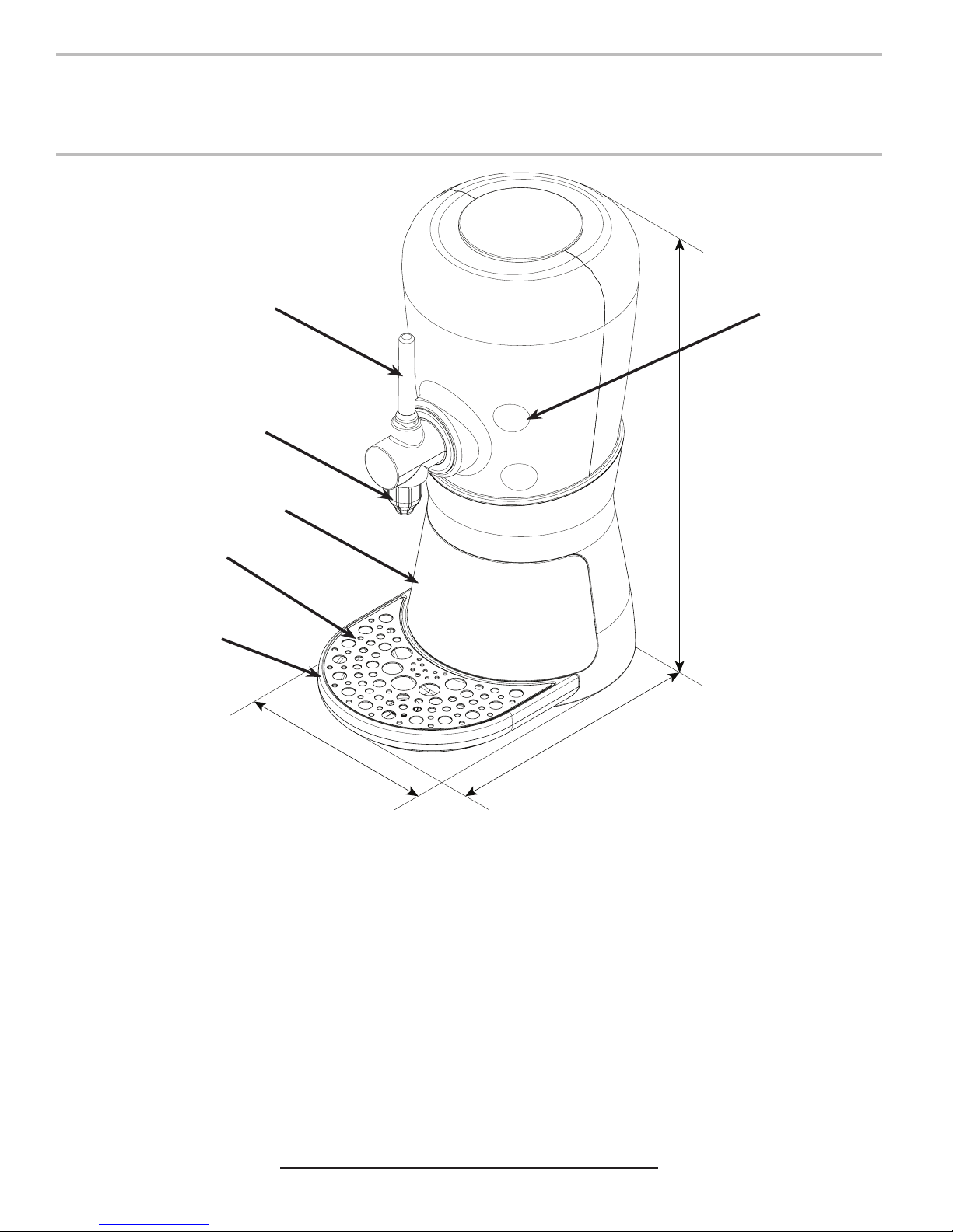
Specications & Features
PRE-INSTALLATION
B
C
22.75 in.
D
E
F
15.5 in.
10.0 in.
A
A. Brand Select
B. Pour Handle
C. Nozzle
D. Front Panel
E. Cup Rest
F. Drip Tray
DIMENSIONS
Width: 10.00 inches (254 mm)
Depth: 15.50 inches (393.7 mm)
Height: 22.75 inches (577.85 mm)
WEIGHT
Shipping: 32.0 lbs (14.5 kg)
Operating: 19.0 lbs (8.6 kg)
ELECTRICAL
24 VDC / 2.0 Amps
FLOW RATE
2.0 ounces per second
This unit emits a sound pressure level below 70 dB
4
PLAIN WATER SUPPLY
Min Flowing Pressure: 25 psi (0.172 MPa)
Max Static Pressure: 65 psi (0.448 MPa)
CARBON DIOXIDE (CO2) SUPPLY
Min Pressure: 70 psi (0.483 MPa)
Max Pressure: 80 psi (0.552 MPa)
FITTINGS AT UNIT
Plain Water Inlet: 3/8 inch (9.5 mm) barb
Brand Syrup Inlets: 3/8 inch (9.5 mm) barb
Drain Fitting: 5/8 inch (15.9 mm) barb
Page 5
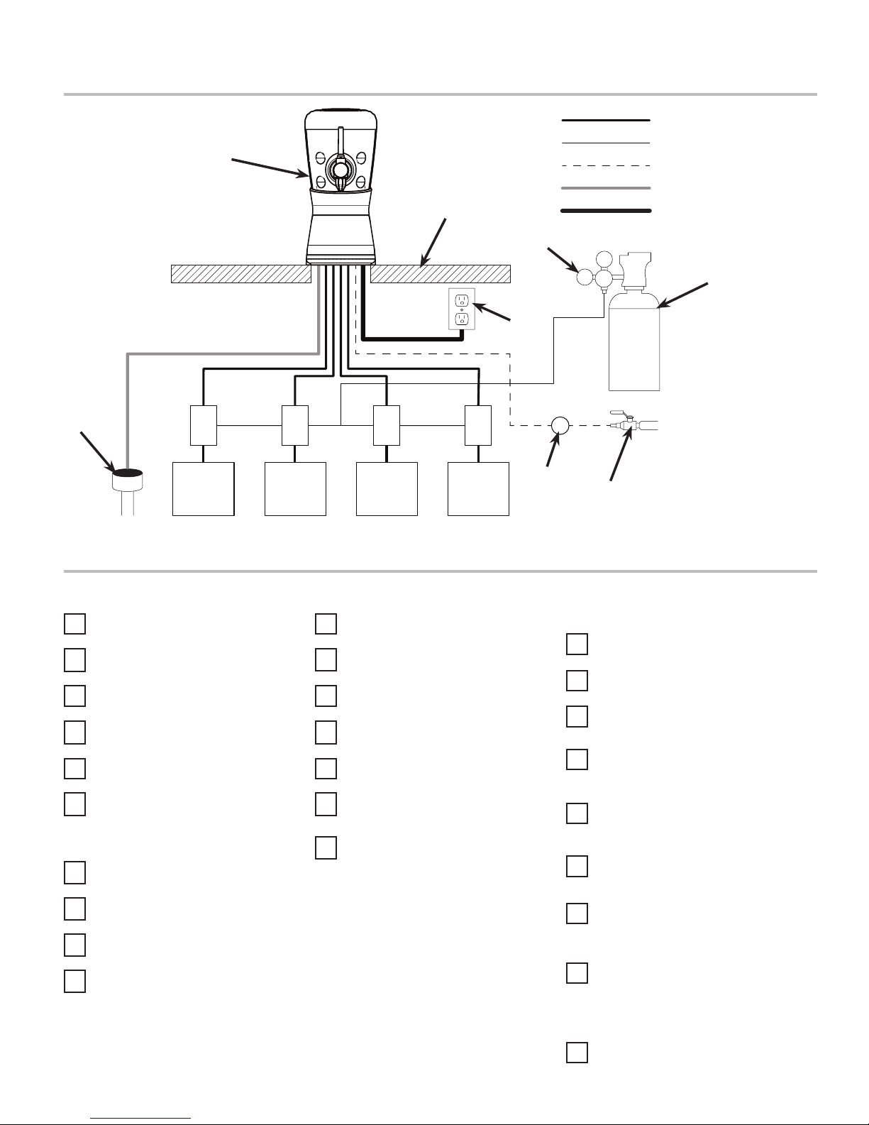
General System Overview - Remote Syrup Pumps
G
F
E
J
H
I I I I
H H H
Syrup Line
CO2 Line
Plain Water Line
Drain Line
Electrical
D
75
C
A. Water Source
B. Water Filter
C. CO2 Source
D. High Pressure CO2
Regulator
E. Electrical Outlet
F. Counter
B
A
G. Tower (Dispenser)
H. Syrup Pump
I. BIB Syrup Containers
J. Floor Drain
Pre-Installation Checklist
TOOLS REQUIRED:
Oetiker Pliers
Tubing Cutters
Wrench
Slotted Screwdriver
Phillips Screwdriver
Drill
BIB SYSTEM:
BIB Rack
BIB Syrup Boxes
BIB Regulator Set
BIB Connectors
POST MIX ACCESSORIES:
CO2 Regulator
CO2 Supply
Chain for CO2 Tank
Beverage Dispenser
Beverage Tubing
Oetiker Clamp Fittings
Water Booster (Lancer PN:
82-3401 or MC-163172
CONSIDER THE FOLLOWING
BEFORE INSTALLATION:
Location of Water Supply Lines
Location of Drain
Location of Electrical Outlet
Location of Heating and Air
Conditioning Ducts
Do you have enough space to
install the dispenser?
Does the counter height meet
ADA requirements?
Is countertop level?
Can the countertop support the
weight of the dispenser? (Include
the weight of an ice machine plus
weight of ice, if necessary)
Is dispenser located away from
direct sunlight or overhead
lighting?
5
Page 6
INSTALLATION
Read This Manual
This manual was developed by Lancer Corporation as a reference guide for the owner/operator and installer of this dispenser.
Please read this manual before installation and operation of this dispenser. Please see pages 13-15 for troubleshooting or service
assistance. If the service cannot be corrected please call your Service Agent or Lancer Customer Service. Always have your
model and serial number available when you call.
Unpacking the Dispenser
1. Cut package banding straps and remove.
2. Open the box and remove the accessory kit and loose
parts.
3. Carefully lift the unit out of the box and place on a at
surface taking care to not scratch the plastic covers.
Selecting/Preparing a Counter Location
NOTE
The dispenser should only be installed in a location
where it can be overseen by trained personnel
1. Select a location that is in close proximity to a properly
grounded electrical outlet, within ve (5) feet (1.5 m) of
a drain, and a water supply that meets the requirements
shown in the Specications section found on page 4.
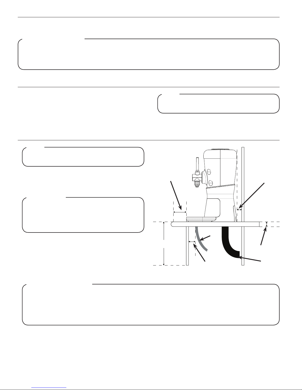
! ATTENTION
Inspect the counter location where the unit is to be
installed. Verify the selected counter is strong enough
to safely support the weight of the installed unit, after
the cutout for the unit is made. The ideal counter for
installation should measure at least one (1) inch thick.
2. Select a location that utilizes the clearances/space required
for installation.
3. Select a location for the syrup pumps, CO2 tank, syrup
containers, and water lter (recommended).
4. Using the base of the tower as a template, cut out required
opening for the tower installation in the designated location.
NOTE
Inspect unit for concealed damage. If evident, notify
delivering carrier and le a claim against the same.
Max: 2.75 in
A
Max: 48.0 in
Min: 2.0 in
Min: 0.75 in
Max: 1.5 in
A. Drain Tube
B. Inlet Tubes
B
Accessibility - ADA
To assure that beverage service is accessible to all customers, Lancer recommends that counter height and
equipment selection be planned carefully. The 2010 ADA Standards for Accessible Design states that the maximum
reach height from the oor should be no more than 48” if touch point is less than 10” from the front of the counter, or
a maximum of 46” if the touch point is more than 10” and less than 27” from the front of the counter. For more
information about the customer’s legal requirements for the accessibility of installed equipment, refer to 2010 ADA
Standards for Accessible Design - http://www.ada.gov.
6
Page 7
Dispenser Installation
NOTE
The installation, and relocation if necessary, must
be carried out by qualied personnel with up-to-date
knowledge and practical experience, in accordance
with current regulations.
1. Place tower on counter in designated location and position
over counter cutout.
2. Attach tower to counter using the three (3) screws provided.
! ATTENTION
When attaching the tower to the counter, make sure
the screws do not extend more than 0.75 in (19 mm)
from the top of the mounting plate. These could
damage the valves when installing the dispenser.
A
B
C
A. Tower
B. Counter Cutout
C
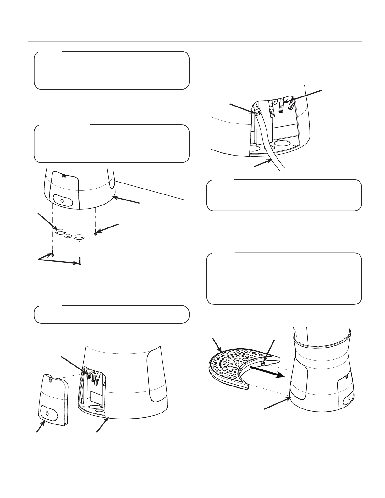
3. After the tower is permanently bolted to the counter top, the
tower base must be sealed to the counter top with a bead
of clear silicone caulk or sealant which provides a smooth
and easily cleanable bond to the counter.
C. Connecting Screws
(Underneath Counter)
NOTE
NSF listed units must be sealed to the counter.
5. Route appropriate tubing from the syrup pump location to
the syrup inlets on the tower. Connect tubing to inlets using
the oetiker pliers and ttings. Repeat for all syrup
connections. (See Plumbing Diagram on page 21 for
reference)
A
C
A. Syrup/Water Inlets
B. Tubing
B
C. Oetiker Fitting
NOTE
The Barrilitos Tower syrup and water lines can either
be routed through the counter cutouts or out through
the back panel of the tower.
6. Route appropriate tubing from the water source to the plain
water inlet at the tower.
7. Cut water line, using tubing cutters, and install water lter to
water line.
NOTE
If the water source is above 65 psi (0.448 MPa), cut
tubing assembly and install Water Regulator Kit (PN
18-0253/02, sold separately) as shown in kit
instruction sheet. Once installed, use a test gauge
assembly (PN 22-0138, sold separately), to set
regulator at a maximum of 65 psi (0.448 MPa).
8. Slide drip tray into opening in tower until magnets engage
and lock drip tray in place.
4. Using a screwdriver, remove the back panel on the tower to
reveal the syrup/water inlets.
C
A
B
A. Back Panel
B. Tower
C. Syrup/Water Inlets
A
B
B
A. Drip Tray
B. Magnet
7
Page 8

9. If a drain line is to be utilized, place gasket at the bottom of
the drain then attach drain tting to drip tray.
B
A. Seal
B. Drip Tray
C
F
E
10. Using two hands, rmly lift the back panel up until the
magnet connection is released and removed from the unit.
C. Counter
D. Upper Drain Fitting
E. Lower Drain Fitting
F. Washer
AD
A
11. Route power cord either up through designated counter
cutout or through back panel, (See step 5) and connect
power cord to unit control board connection.
A
B
A. Power Cord Connection
B. Counter Cutout/
Back Panel Access
12. Plug in power cord to power supply then route power supply
cord to the designated grounded electrical outlet.
! WARNING
The dispenser must be properly electrically grounded
to avoid serious injury or fatal electrical shock. The
power cord has a three-prong grounded plug. If a
three-hole grounded electrical outlet is not available,
use an approved method to ground the unit. Follow
all local electrical codes when making connections.
Each dispenser must have a separate electrical circuit.
Do not use extension cords. Do not connect multiple
electrical devices on the same outlet.
A. Back Panel
To congure the light ring to a specic color for each
Adjust Water Flow Rate & Syrup/Water Ratio
1. Remove the front panel from the tower by pulling away from
the unit and disengaging the magnets.
B
A
A. Front Panel
B. Water/Syrup Valves
2. Use the brand buttons to enter the Technician Mode, (see
section Technician Mode, on page 9, for reference).
3. Perform a 8 second water pour (see page 10) and using a
4. Use the chart below to determine the proper ow of water
NOTE
brand, see DIP Switch Settings on page 20.
graduated cylinder, verify water ow rate.
B
A
A. Graduated Cylinder
B. Nozzle
needed according to the ratio of the products being used.
8
Page 9

5. Use a screwdriver to adjust the ow if needed, (See
plumbing diagram on page 19 for reference). Repeat Steps
3-5 until proper ow of water is achieved.
B
A
Increase Decrease
A. Flow Control
C
B. Solenoid
C. Valve Body
6. Perform a 8 second syrup pour (see page 10) of the rst
syrup line and using a graduated cylinder, verify syrup ow
rate.
7. Use the chart below to determine the proper ow of syrup
needed according to the ratio of the syrup being used.
8. Use a screwdriver to adjust if needed. Repeat Steps 6 - 8
until proper ow of syrup is achieved.
9. Repeat Steps 6 - 8 for remaining syrup lines.
Target Flow Rate
Ratio (X:1) 4.00 4.25 4.50 4.75 5.00 5.25 5.50 5.75 6.00
Plain Water Volume
(8 sec.)
Volume of Syrup
(8 sec.)
12.80 oz
(378.51 ml)
3.20 oz
(94.64 ml)
12.95 oz
(382.98 ml)
3.05 oz
(90.20 ml)
Normal Operation Mode
Starting a Normal Pour
when no Brand is Selected.
Starting a Normal Pour with
Lever , when Brand is
Already Selected.
13.09 oz
(387.12 ml)
2.91 oz
(86.06 ml)
13.22 oz
(390.96 ml)
2.72 oz
(80.44 ml)
13.33 oz
(394.22 ml)
2.67 oz
(78.96 ml)
13.44 oz
(397.47 ml)
2.56 oz
(75.71 ml)
13.54 oz
(400.43 ml)
2.46 oz
(72.75 ml)
13.63 oz
(403.09 ml)
2.37 oz
(70.09 ml)
13.72 oz
(405.75 ml)
2.28 oz
(67.43 ml)
MODES OF OPERATION
1. The lever is in the OFF state and no brand is selected.
2. Pull the lever down, all brand button LEDs will illuminate for 3 seconds.
3. Touch the brand button to select and initiate pour. The selected brand LED will turn ON
and all others will turn OFF. Light ring will turn ON and match the color specied by the
associated DIP switch conguration.
4. Pour stops when lever is released (or after 15 seconds)
1. The lever is in the OFF state and a brand is already selected. The brands’ LED is ON and
the light ring matches the color specied by the associated DIP switch conguration.
2. Pull the lever down, pour of brand syrup and water begins.
3. Pour stops when lever is released (or after 15 seconds)
1. The selected brands’ LED is ON and the light ring matches the color specied by the as-
Deselecting a Brand
Dispense/Settle Mode
2. Brand button is automatically deselected after 30 seconds of inactivity. Brand LED turns
1. Once a Normal Pour is activated, the dispenser is in Dispense Mode and a manual pour
2. Once pour stops and the lever is released, the dispenser is in Settle Mode which allows
3. Brand button is automatically deselected after 30 seconds of inactivity. Brand LED turns
sociated DIP switch conguration.
OFF and the light ring returns to the white color.
of brand syrup and water is initiated.
for a top-o of the selected brand.
OFF and the light ring returns to the white color.
9
Page 10

Technician Mode
Enter Technician Mode
Timed Pour of Water and
Syrup
1. Technician mode can only be entered within one (1) minute after startup. If the unit has
been powered on for more than one minute, cycle power then begin the process to enter
the Technician Mode.
2. Press and hold the top two brand buttons simultaneously for two (2) seconds.
• The top two brand buttons must be pressed within 1 minute of unit power up.
3. After the two (2) seconds, the top two brand button LEDs will turn ON. Release the top
two brand buttons then press and hold the bottom two brand buttons for two (2) seconds.
• The bottom two brand buttons must be pressed within 10 seconds of releasing the
top two brand buttons.
4. After the two (2) seconds, the bottom two brand button LEDs will turn ON. Release the
bottom two brand buttons to activate Technician Mode.
• The bottom two brand buttons must be released within 1 second of brand button
LEDs turning ON.
• If successful, the four button LEDs will blink 4 times.
• If the user is unsuccessful in entering the Technician Mode, re-cycle power and
repeat the process.
1. The lever is in the OFF state and no brand is selected.
2. Pull and release lever 4 times within a span of 4 seconds.
• Pulls must be within 1 second of each other.
3. Select and release any brand within one second to begin pour.
• Pull lever or press any button to cancel pour in progress.
Timed Pour of Syrup
Timed Pour of Water
Exit Technician Mode
(Manually)
1. The lever is in the OFF state and no brand is selected.
2. Pull and release lever 5 times within a span of 5 seconds.
• Pulls must be within 1 second of each other.
3. Select and release any brand within one second to begin pour.
• Pull lever or press any button to cancel pour in progress.
1. The lever is in the OFF state and no brand is selected.
2. Pull and release lever 6 times within a span of seconds.
• Pulls must be within 1 second of each other.
3. Select and release any brand within one second to begin pour.
• Pull lever or press any button to cancel pour in progress.
1. The lever is in the OFF state, no brand is selected, and dispenser is in Technician Mode.
2. Press and hold the top two brand buttons simultaneously for two (2) seconds.
3. The top two brand button LEDs will turn ON, release the top two brand buttons then press
and hold the bottom two brand buttons for two (2) seconds.
• The bottom two brand buttons must be pressed within 10 seconds of releasing the
top two brand buttons.
4. The bottom two brand button LEDs will turn ON, release the bottom two brand buttons to
exit Technician Mode.
• The bottom two brand buttons must be released within 1 second of brand button
LEDs turning ON.
• If successful, the four button LEDs will blink twice.
Exit Technician Mode
(Automatically)
1. The dispenser will automatically exit the Technician Mode and return to the Normal
Operation Mode after 3 minutes of inactivity.
10
Page 11

LED Saver Mode
Enter LED Saver Mode
Exit LED Saver Mode (Brand
Button)
1. With the dispenser in the Normal Operation Mode, the LEDs and light ring will turn o
after 2 hours of inactivity.
2. After the dispenser is in the LED Saver Mode and the LEDs and light ring have been o
for 1 minute, the light ring will begin a color ramp sequence.
1. With the dispenser in the LED Saver Mode, touch any brand button to change to Normal
Operation Mode.
2. The selected brand LED will turn ON and all others will turn OFF. Light ring will turn ON
and match the color specied by the associated DIP switch conguration.
Exit LED Saver Mode
(Activate Lever)
1. With the dispenser in the LED Saver Mode, pull the lever down to change to Normal
Operation Mode.
2. The brand button LEDs remain o and the light ring turns white.
CLEANING AND SANITIZING
General Information
• Lancer equipment (new or reconditioned) is shipped from the factory cleaned and sanitized in accordance with NSF guidelines.
The operator of the equipment must provide continuous maintenance as required by this manual and/or state and local health
department guidelines to ensure proper operation and sanitation requirements are maintained.
NOTE
The cleaning procedures provided herein pertain to the Lancer equipment identied by this manual. If other
equipment is being cleaned, follow the guidelines established by the manufacturer for that equipment.
• Cleaning should be accomplished only by trained personnel. Sanitary gloves are to be used during cleaning operations.
Applicable safety precautions must be observed. Instruction warnings on the product being used must be followed.
! ATTENTION
• Use sanitary gloves when cleaning the unit and observe all applicable safety precautions.
• DO NOT use a water jet to clean or sanitize the unit.
• DO NOT disconnect water lines when cleaning and sanitizing syrup lines, to avoid contamination.
• DO NOT use strong bleaches or detergents; These can discolor and corrode various materials.
• DO NOT use metal scrapers, sharp objects, steel wool, scouring pads, abrasives, or solvents on the dispenser.
• DO NOT use hot water above 140° F (60° C). This can damage the dispenser.
• DO NOT spill sanitizing solution on any circuit boards. Insure all sanitizing solution is removed from the system.
Cleaning and Sanitizing Solutions
Cleaning Solution
Mix a mild, non-abrasive detergent (e.g. Sodium Laureth
Sulfate, dish soap) with clean, potable water at a temperature of
90°F to 110°F (32°C to 43°C). The mixture ratio is one ounce of
cleaner to two gallons of water. Prepare a minimum of ve
gallons of cleaning solution. Do not use abrasive cleaners or
solvents because they can cause permanent damage to the
unit. Ensure rinsing is thorough, using clean, potable water at a
temperature of 90°F to 110°F. Extended lengths of product lines
may require additional cleaning solution.
Sanitizing Solution
Prepare the sanitizing solution in accordance with the
manufacturer’s written recommendations and safety guidelines.
The type and concentration of sanitizing agent recommended
in the instructions by the manufacturer shall comply with 40
CFR §180.940. The solution must provide 100 parts per million
(PPM) chlorine (e.g. Sodium Hypochlorite or bleach) and a
minimum of ve gallons of sanitizing solution should be
prepared.
11
Page 12

Scheduled Maintenance and Cleaning
As Needed
Daily
Weekly
Every Six Months
• Keep exterior surfaces of dispenser (include drip tray and cup rest) clean using a clean, damp
cloth.
• Remove each nozzle and rinse well in warm water. DO NOT use soap or detergent. This will
cause foaming and o taste in nished product.
• Using a soft cloth and cleaning solution, clean the nozzle injectors. See Cleaning and Sanitizing
Nozzle section on page 12 for reference.
• Remove cup rest and wash in warm soapy water.
• Pour warm soapy water into the drip tray and wipe with a clean cloth.
• With a clean cloth and warm water, wipe o all of the unit’s exterior surfaces. DO NOT USE
ABRASIVE SOAPS OR STRONG DETERGENTS.
• Replace the cup rest and nozzle
• Taste each product for o tastes. If o taste occurs, clean and sanitize the unit using the
appropriate procedures outlined in the Cleaning and Sanitizing section of this manual.
• Clean and sanitize the unit using the appropriate procedures outlined in the Cleaning and
Sanitizing section of this manual.
Cleaning and Sanitizing Nozzle
1. Disconnect power, so as to not activate valve while cleaning.
2. Remove outer nozzle by twisting clockwise and pulling
down.
A
A
A. Front Panel
B. Water/Syrup Valves
3. Rinse nozzle with warm water.
4. Thoroughly wash the nozzle using a clean soft cloth and
cleaning solution described on previous page.
5. Using the nozzle brush (Lancer PN: 22-0017) included with
the unit and cleaning solution described on the previous
page, thoroughly clean the vent located on the nozzle.
A. Nozzle Vent
6. Immerse the nozzle in sanitizing solution and let sit for
fteen (15) minutes.
7. Set nozzle aside and let air dry. DO NOT rinse with water
after sanitizing.
8. Using a soft, clean cloth and cleaning solution, clean the
nozzle injectors.
9. Using a soft, clean cloth, sanitize the nozzle injectors and
let air dry.
10. Reconnect nozzle.
11. Connect power.
12. Taste the drink to verify that there is no o-taste. If o-taste
is found, sanitize the nozzle and nozzle injectors again.
! CAUTION
Following sanitization, rinse with end-use product
until there is no aftertaste. Do not use a fresh water
rinse. This is a NSF requirement. Residual sanitizing
solution left in the system creates a health hazard.
12
Page 13

Cleaning and Sanitizing Syrup Lines - BIB
1. Disconnect syrup lines from BIB’s
2. Place syrup lines, with BIB connectors, in a bucket of warm
water.
3. Activate each valve to ll the lines with warm water and
ush out syrup remaining in the lines.
4. Prepare Cleaning Solution described above.
5. Place syrup lines, with BIB connectors, into cleaning
solution.
6. Activate each valve until lines are lled with cleaning
solution then let stand for ten (10) minutes.
7. Flush out cleaning solution from the syrup lines using clean,
warm water.
8. Prepare Sanitizing Solution described above.
9. Place syrup lines into sanitizing solution and activate each
valve to ll lines with sanitizer. Let sit for ten (10) minutes.
10. Reconnect syrup lines to BIB’s and draw drinks to ush
solution from the dispenser.
11. Taste the drink to verify that there is no o-taste. If o-taste
is found, ush syrup system again.
! CAUTION
Following sanitization, rinse with end-use product
until there is no aftertaste. Do not use a fresh water
rinse. This is a NSF requirement. Residual sanitizing
solution left in the system creates a health hazard.
TROUBLESHOOTING
TROUBLE CAUSE REMEDY
Water leakage around nozzle. 1. O-ring is damaged or missing. 1. Replace o-ring.
Miscellaneous leakage. 1. Gap between parts.
2. Damaged or improperly installed o-rings.
1. Tighten appropriate retaining screws
2. Replace or adjust appropriate o-rings
Insucient water ow. 1. Insucient incoming supply water
pressure.
2. Shuto on mounting block not fully open.
3. Foreign debris in water ow control.
4. Foreign debris in water pump strainer
Insucient syrup ow. 1. Insucient CO2 pressure to BIB pumps.
2. Out of CO2 .
3. Shuto on mounting block not fully open.
4. Foreign debris in syrup ow control.
5. Bad syrup pump.
Erratic ratio. 1. Incoming water and/or syrup supply not at
minimum owing pressure.
2. Foreign debris in water and/or syrup ow
controls.
1. Verify incoming supply water pressure is a
minimum of 25 psi (0.172 MPa).
2. Open shuto fully.
3. Remove water ow control from upper
body and clean out any foreign material to
ensure smooth free spool movement.
4. Remove water pump strainer and clean.
1. Adjust CO2 pressure to 80 psi (0.550 MPa)
[minimum 70 psi (0.480 MPa)] for BIB
pumps.
2. Replace CO2 tank/rell.
3. Open shuto fully.
4. Remove syrup ow control form upper
body and clean out any foreign material to
ensure smooth free spool movement.
5. Replace BIB pump.
1. Check pressure and adjust
2. Remove ow controls from upper body and
clean out any foreign material to ensure
smooth free spool movement.
13
Page 14

TROUBLE CAUSE REMEDY
No syrup dispensed 1. Water and syrup shutos on mounting
block not fully open.
2. Electric current not reaching valve.
3. Improper or inadequate water or syrup
supply.
4. Transformer Failure
5. Bad valve solenoid(s)
Water only dispensed; no
syrup; or syrup only dispensed,
no water
1. Water or syrup shuto on mounting block
not fully open.
2. Improper or inadequate water or syrup
ow.
3. BIB supply too far from dispenser.
4. CO2 pressure too low.
5. Stalled or inoperative BIB pump
6. Kinked line.
1. Open shuto fully.
2. Check electric current supplied to valve.
If current is adequate, check solenoid coil
and switch, and replace if necessary.
3. Remove valve from mounting block and
open shutos slightly and check water and
syrup ow. If no ow, check dispenser for
freeze-up or other problems
4. Reset transformer circuit breaker. If
breaker trips again check for pinched wire
harness at backblocks
5. Replace Solenoid(s)
1. Open shuto fully.
2. Remove valve from mounting block, open
shutos slightly and check water and
syrup ow. If no ow, check dispenser for
freeze-up or other problems. Ensure BIB
connection is engaged.
3. Check that BIB supply is within six (6) feet
of the dispenser.
4. Check the CO2 pressure to the pump
manifold to ensure it is between 70 and 80
psi (0.483 and 0.552 MPa).
5. Check CO2 pressure and/or replace pump.
6. Remove kink or replace line.
Syrup only dispensed. No
water, but CO2 gas dispensed
with syrup.
Excessive foaming. 1. Incoming water or syrup temperature too
Warm drinks. 1. Restricted airow.
1. Improper water ow to dispenser.
2. Carbonator pump motor has timed out.
high.
2. CO2 pressure too high.
3. Water ow rate too high.
4. Nozzle not installed correctly.
5. Nozzle and nozzle injectors not clean.
6. Air in BIB lines.
7. Poor quality ice.
8. High beverage temperature.
2. Dispenser connected to hot water supply.
3. Dispenser capacity exceeded.
1. Check for water ow to dispenser (see
Insucient Water Flow on previous page).
2. Reset by turning the unit OFF and then
ON.
1. Correct prior to dispenser. Consider larger
dispenser or pre-cooler.
2. Adjust CO2 pressure downward, but not
less than 70 psi (0.483 MPa).
3. Re-adjust and reset ratio. Refer to “Adjust
Water Flow Rate & Syrup/Water Ratio”
Section.
4. Remove and reinstall properly.
5. Remove nozzle and clean injectors.
6. Bleed air from BIB lines.
7. Check quality of ice used in drink.
8. Check refrigeration system.
1. Check clearances around sides, top, and
inlet of unit. Remove objects blocking
airow through grill.
2. Switch to cold water supply.
3. Add pre-cooler or replace with larger
dispenser.
14
Page 15

TROUBLE CAUSE REMEDY
Circuit breaker tripping. 1. Valve wire harness shorted to itself or to
faucet plate.
2. PCB is bad.
3. Secondary wire harness is bad.
4. Transformer failure.
Handle feels loose during
operation
1. Defective or broken handle return spring 1. Un-thread two screws in Faucet Hous-
1. Detect short by disconnecting input fasten
to keylock and single pin connector.
Restore power if breaker doesn’t trip.
Then valve wire harness is shorted. If OK,
reconnect.
2. Detect short by disconnecting J1
connector (24 VAC input) from PCB.
Restore power, if breaker doesn’t trip.
Then replace PCB. If breaker does trip,
then PCB is OK. Reconnect J1 connector.
3. If it does not trip, locate short in secondary
harness between transformer, PCB, and
valve wire harness.
4. Detect short by disconnecting both
transformer fastens and restore power. If
breaker does trip, replace transformer.
ing Assembly and replace upper nozzle/
handle assembly.
2. Remove handle pin then slide up on
handle to replace spring. Re-align the
handle, cam, and actuator then reinstall
handle pin.
BIB pump does not operate
when dispensing valve opened.
BIB pump operated, but no
ow.
BIB pump continues to operate
when bag is empty.
BIB pump fails to restart after
bag replacement.
BIB pump fails to restart when
dispensing valve is closed.
1. Out of CO2, CO2 not turned on, or low CO2
pressure.
2. Out of syrup.
3. BIB connector not tight.
4. Kinks in syrup or gas lines.
5. Bad BIB Pumps.
1. Leak in syrup inlet or outlet line.
2. Defective BIB pump check valve.
1. Leak in suction line.
2. Leaking o-ring on pump inlet tting.
1. BIB connector not on tight.
2. BIB connector is stopped up.
3. Kinks in syrup line
4. Bad BIB Pumps.
1. Leak in discharge line or ttings.
2. Empty BIB.
3. Air leak on inlet line or bag connector.
1. Replace CO2 supply, turn on CO2
supply, or adjust CO2 pressure to 70-80 psi
(0.483-0.552 MPa)
2. Replace syrup supply.
3. Fasten connector tightly.
4. Straighten or replace lines.
5. Replace BIB pump.
1. Replace line.
2. Replace BIB pump
1. Replace line.
2. Replace o-ring.
1. Tighten BIB connector.
2. Clean out or replace BIB connector.
3. Straighten or replace line.
4. Replace BIB pump.
1. Repair or replace discharge
2. Replace BIB.
3. Repair or replace.
Low or no carbonation. 1. Low or no CO2.
2. Excessive water pressure.
3. Worn or defective carbonator pump.
1. Check CO2 supply. Adjust CO2 pressure to
70 psi (0.483 MPa).
2. Water regulator should be set at 65 psi
(0.448 MPa)
3. Replace carbonator pump.
15
Page 16

ILLUSTRATIONS AND PART LISTINGS
Main Unit Assembly
21
19
16
17
18
09
01
11
03
02
04
10
08
14
12 x4
15
13 x4
20
05
06
07
Item Part No. Description
01 30-13230 Cup Rest, BBT
02 01-2994 Drain Fitting, 1/2 NPT
03 02-0677 Seal, Washer, Drain
04 54-0554 Drip Tray Assy, BBT
05 04-1710/01 Washer, Flat
06 01-2991 Coupling, Female
07 82-5000 Drain Kit, BBT
08 05-3719/01 Splash Plate, BBT
09 82-5290 Faucet Housing Assy, BBT
10 54-0557 Nozzle Assy, BBT
16
11 19-0560 Valve Assy, CVM, Water, 2.0 oz
12 19-0559 Valve Assy, CVM, Syrup, 2.0 oz
13 82-2317/01 Mounting Block Assy
14 52-3954 Lever Harness, BBT
15 52-3955 Solenoid Harness, BBT
16 64-5136 PCB Assy, Main Controller
17 52-3953 Power Harness
18 82-5291 Button Panel Assy, BBT
19 12-0666 RGBW LED Strips
20 05-3720 Rear Hatch, BBT
21 82-5272 Rear Jar, BBT
Page 17

Faucet Housing Assembly
01
02
09
04
03
06
05
07
08
Item Part No. Description
01 05-3756 Faucet Handle, BBT
02 05-3757 Faucet Cam, BBT
03 10-1019 Actuator Pin
04 04-0549 Screw, 6-19 x 0.625
05 05-3765 Washer
06 05-3759 Upper Faucet Housing, BBT
07 03-0530 Faucet Spring
08 82-5297 Actuator Assembly w/ Magnet
09 64-5028 PCB Assembly, Hall Sensor
10 04-0699 Screw, 6-19 x 0.250
10
17
Page 18

Button Panel Assembly
01 x4
02
03
Item Part No. Description
01 04-1639/01 Screw, 4-20 x 0.250
02 52-3956 Buttons Harness, BBT
03 05-3726 Button Panel, BBT
04 82-5298 Button PCB Assembly
18
04
Page 19

Wiring Diagram
19
Page 20

DIP Switch Settings
NOTE
The following table shows the DIP switch settings that correlate the 16 colors and Barrilitos brand names available on
the Barrilitos Tower.
DIP Switch Cong Color/Brand Name
Mango Lime **Switch 1 Default Position**
Pear Cucumber **Switch 2 Default Position**
Pineapple **Switch 3 Default Position**
Strawberry Hibiscus **Switch 4 Default Position**
Passionfruit Orange
Watermelon
Guava
Horchata
Tamarindo
Lemonade
Lime
Blueberry
Red
20
Green
Blue
White
Page 21

Plumbing Diagram
S4
S3 S2
S4
S1
S3
PW
S2 S1
Item Description
S1 Syrup Line 1
S2 Syrup Line 2
S3 Syrup Line 3
S4 Syrup Line 4
PW Plain Water Line
Dispenser Disposal
To prevent possible harm to the environment from improper disposal, recycle the unit
by locating an authorized recycler or contact the retailer where the product was
purchased. Comply with local regulations regarding disposal of the refrigerant and
insulation.
21
Page 22

Lancer Corp.
800-729-1500
Technical Support/Warranty: 800-729-1550
custserv@lancercorp.com
lancercorp.com
 Loading...