

Page 1
Bar Bridge
DRAFT
Lancer Corporation
6655 Lancer Blvd.
San Antonio, Texas 78219
800-729-1500
Operation Manual
“Lancer” is the registered trademark of Lancer © 2014 by Lancer, all rights reserved.
Technical Support/Warranty
800-729-1550
custserv@lancercorp.com
lancercorp.com
PN: 28-0941/01
Page 2

TABLE OF CONTENTS
DRAFT
ABOUT THIS MANUAL
This booklet is an integral and essential part of the product and
should be handed over to the operator after the installation and
preserved for any further consultation that may be necessary.
Please read carefully the guidelines and warnings contained
herein as they are intended to provide the user with essential
information for the continued safe use and maintenance of the
product. In addition, it provides GUIDANCE ONLY to the user
on the correct services and site location of the unit.
The installation and relocation, if necessary, of this product must be carried out by qualied personnel with
up-to-date safety and hygiene knowledge and practical experience, in accordance with current regulations.
IMPORTANT SAFETY INSTRUCTIONS..........................3
Intended Use..............................................................3
Power Warning...........................................................3
CO2 Warning...............................................................3
Water Notice...............................................................3
SPECIFICATIONS AND FEATURES...............................4
General Systems Overview........................................5
PRE-INSTALLATION CHECKLIST...............................5-6
INSTALLATION................................................................6
Unpacking the Dispenser............................................6
Selecting/Preparing a Counter Location.....................6
Dispenser/Chiller Installation...................................7-8
Installing Remote Syrup Pumps.................................9
Installing CO2 Supply...........................................10-11
Connecting to Syrup Supply......................................11
Dispenser Setup..................................................11-12
Adjust Water Flow Rate & Syrup/Water Ratio.....12-13
Merchandiser Installation..........................................13
BEFORE GETTING STARTED
Each unit is tested under operating conditions and is thoroughly
inspected before shipment. At the time of shipment, the
carrier accepts responsibility for the unit. Upon receiving the
unit, carefully inspect the carton for visible damage. If
damage exists, have the carrier note the damage on the freight
bill and le a claim with carrier. Responsibility for damage to the
dispenser lies with the carrier.
MAINTENANCE.............................................................14
Scheduled Maintenance...........................................14
CLEANING AND SANITIZING.......................................14
General Information..................................................14
Cleaning and Sanitizing Solutions............................15
Cleaning and Sanitizing Product Lines.....................15
Cleaning and Sanitizing Nozzle...........................15-16
TROUBLESHOOTING...............................................16-18
DISPENSER DISPOSAL................................................18
ILLUSTRATIONS AND PART LISTINGS.......................19
Main Unit Assembly..................................................19
Unit Plumbing Diagram.............................................20
Unit Wiring Diagram..................................................21
READ ALL SAFETY INSTRUCTIONS BEFORE USING THIS UNIT.
This manual contains important safety information and all applicable safety precautions must be observed. To reduce
the risk of re, electric shock, damage to the equipment or personal injury when using this unit all instuctions/warnings
on the product being used must be followed:
! WARNING
Text following the Warning signal indicates a
hazardous situation, which if not avoided, will result
in death or serious injury. Be sure to read all Warning
statements before proceeding with the installation.
! CAUTION
Text following the Caution signal indicates a
hazardous situation, which if not avoided, could result
in death or serious injury. Be sure to read the Caution
statements before proceeding with the installation
2
SAFETY NOTICES
! ATTENTION
Text following the Attention signal addresses a
situation that if not followed could potentially damage
the equipment. Be sure to read the Attention
statements before proceeding
NOTE
Text following the Note signal provides you with
information that may help you more effectively perform
the installation procedures within this manual.
Disregarding information will not cause damage or
injury, however it may limit the performance of the
dispenser.
Page 3
IMPORTANT SAFETY INSTRUCTIONS
DRAFT
! Intended Use F Power
• The dispenser is for indoor use only
• This appliance is intended to be used in commercial
applications such as restaurants or similar.
• This appliance should not be used by children or
inrm persons without supervision.
• This appliance is not intended for use by persons
(including children) with reduced physical, sensory
or mental capabilities, or lack of experience and
knowledge, unless they have been given supervision
or instruction concerning use of the appliance by a
person responsible for their safety.
• This appliance can be used by children aged from 8
years and above and persons with reduced physical,
sensory or mental capabilities or lack of experience
and knowledge if they have been given supervision or
instruction concerning use of the appliance in a safe
way and understand the hazards involved.
• Cleaning and user maintenance shall not be
performed by children without supervision.
• This unit is not a toy and children should be advised
not to play with the appliance.
• The min/max ambient operating temperature for the
dispenser is 4°C to 32°C (40°F to 90°F).
• Do not operate unit below minimum ambient operation
conditions.
• Should freezing occur, cease operation of the unit and
contact authorized service technician.
• The maximum tilt for safe operation is 5°.
• This appliance must be installed and serviced by a
professional.
5 Carbon Dioxide (CO2)
• WARNING: Carbon Dioxide (CO
noncombustible gas with a light pungent odor. High
percentages of CO2 may displace oxygen in the
blood.
• WARNING: Prolonged exposure to CO
Personnel exposed to high concentrations of CO2 gas
will experience tremors which are followed by a loss
of consciousness and suffocation.
• WARNING: If a CO
ventilate the contaminated area before attempting to
repair the leak.
• WARNING: Strict attention must be observed in the
prevention of CO2 gas leaks in the entire CO2 and soft
drink system.
gas leak is suspected, immediately
2
) is a colorless,
2
can be harmful.
2
• Follow all local electrical codes when making
connections.
• Check the dispenser serial number plate for
correct electrical requirements of unit. DO NOT plug
into a wall electrical outlet unless the current shown
on the serial number plate agrees with local current
available.
• Each dispenser must have a separate electrical
circuit.
• DO NOT use extension cords with this unit.
• DO NOT ‘gang’ together with other electrical devices
on the same outlet.
• WARNING: Always disconnect electrical power to the
unit to prevent personal injury before attempting any
internal maintenance.
• The resettable breaker switch should not be used as
a substitute for unplugging the dispenser from the
power source to service the unit.
• Only qualied personnel should service internal
components of electrical control housing.
• WARNING: Make sure that all water lines are tight and
units are dry before making any electrical connections
• If this dispenser is installed in an area that is
susceptible to ±10% variation of the nominal line
voltage, consider installing a surge protector or similar
protection device.
! Water Notice
• Provide an adequate, potable water supply. Water
pipe connections and xtures directly connected to
a potable water supply must be sized, installed, and
maintained according to federal, state, and local
codes.
• The water supply line must be at least a 9.525 mm
(3/8 inches) pipe with a minimum of 20 PSI (0.137
MPA) line pressure, but not exceeding a maximum of
50 PSI (0.345 MPA). Water pressure exceeding 50
PSI (0.345 MPA) must be reduced to 50 PSI (0.345
MPA).
• Use a lter in the water line to avoid equipment
damage and beverage off-taste. Check the water lter
periodically, as required by local conditions.
• CAUTION: The water supply must be protected by
means of an air gap, a backow prevention device
(located upstream of the CO2 injection system)
or another approved method to comply with NSF
standards. A leaking inlet water check valve will
allow carbonated water to ow back through the pump
when it is shut off and contaminate the water supply.
• CAUTION: Ensure the backow prevention device
complies with ASSE and local standards. It is the
responsibility of the installer to ensure compliance.
3
Page 4
SPECIFICATIONS AND FEATURES
DRAFT
A
G
361.5 mm
D
C
244 mm
E
F
344.5 mm
310 mm
F
110 mm
195.23 mm 295.24 mm
C
G
E
C
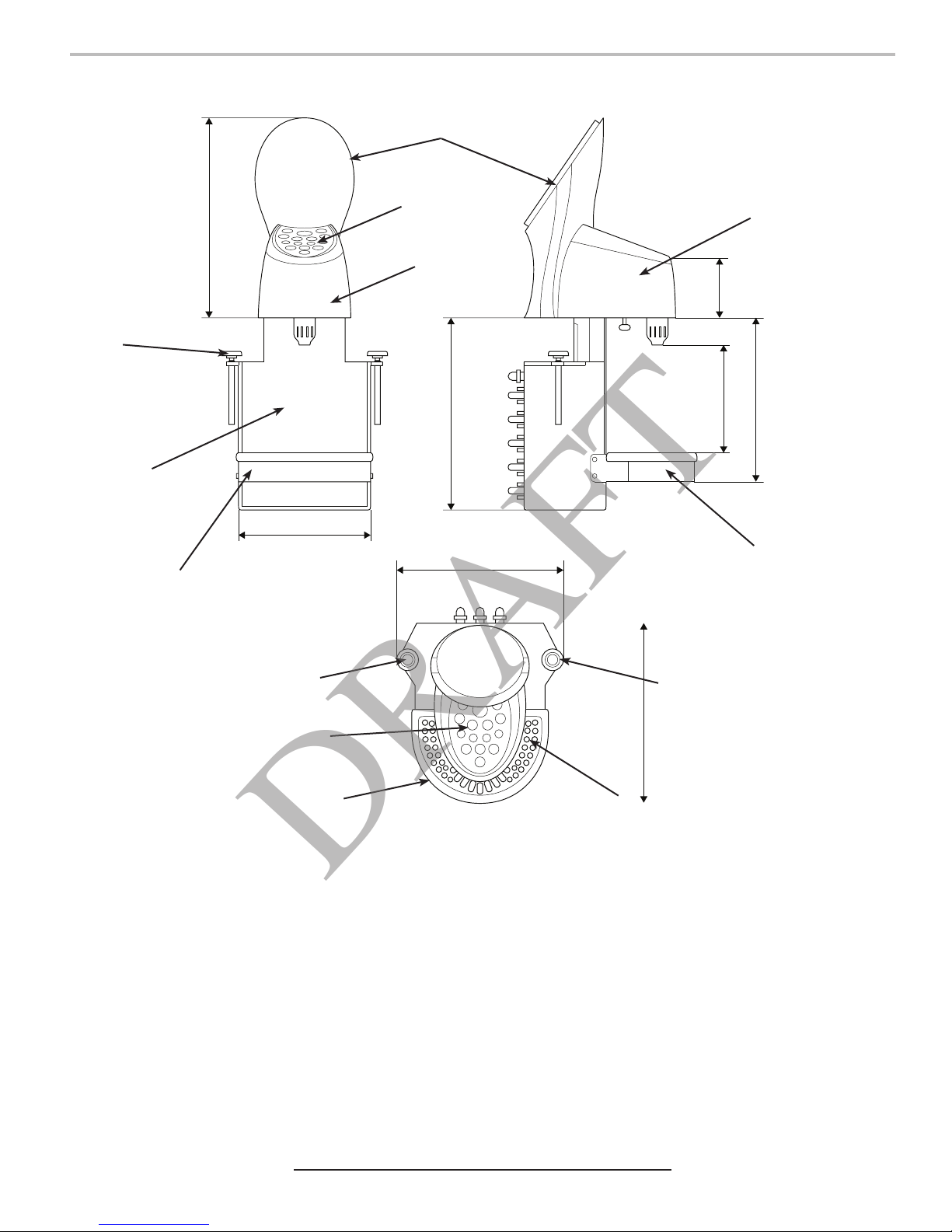
DIMENSIONS
Width: 310 mm (XX inches)
Depth: 335.8 mm (XX inches)
Height: 706 mm (XX inches)
WEIGHT
Shipping: XX kg (XX lbs)
Operating: XX kg (XX lbs)
ELECTRICAL
XXX VAC / XX Hz / X Amps
FLOW RATE
1.5 ounces per second
4
This unit emits a sound pressure level below 70 dB
G
A. Tower
B. Drip Plate
C. Drip Tray
D. Splash Housing
E. Keypad
B
PLAIN WATER SUPPLY
Min Flowing Pressure: 20 PSIG (0.137 MPA)
Max Static Pressure: 50 PSI (0.345 MPA)
CARBON DIOXIDE (CO2) SUPPLY
Min Pressure: 70 PSIG (0.483 MPA)
Max Pressure: 80 PSIG (0.552 MPA)
FITTINGS
Carb Water Recirc.: 9.5 mm (3/8 inch) barb
Plain Water Inlet: 9.5 mm (3/8 inch) barb
Brand Syrup Inlets: 9.5 mm (3/8 inch) barb
Flavor Injector Inlets: 6.4 mm (1/4 inch) barb
CO2 Inlet: 9.5 mm (3/8 inch) barb
F. Plastic Housing
G. Clamp
Page 5
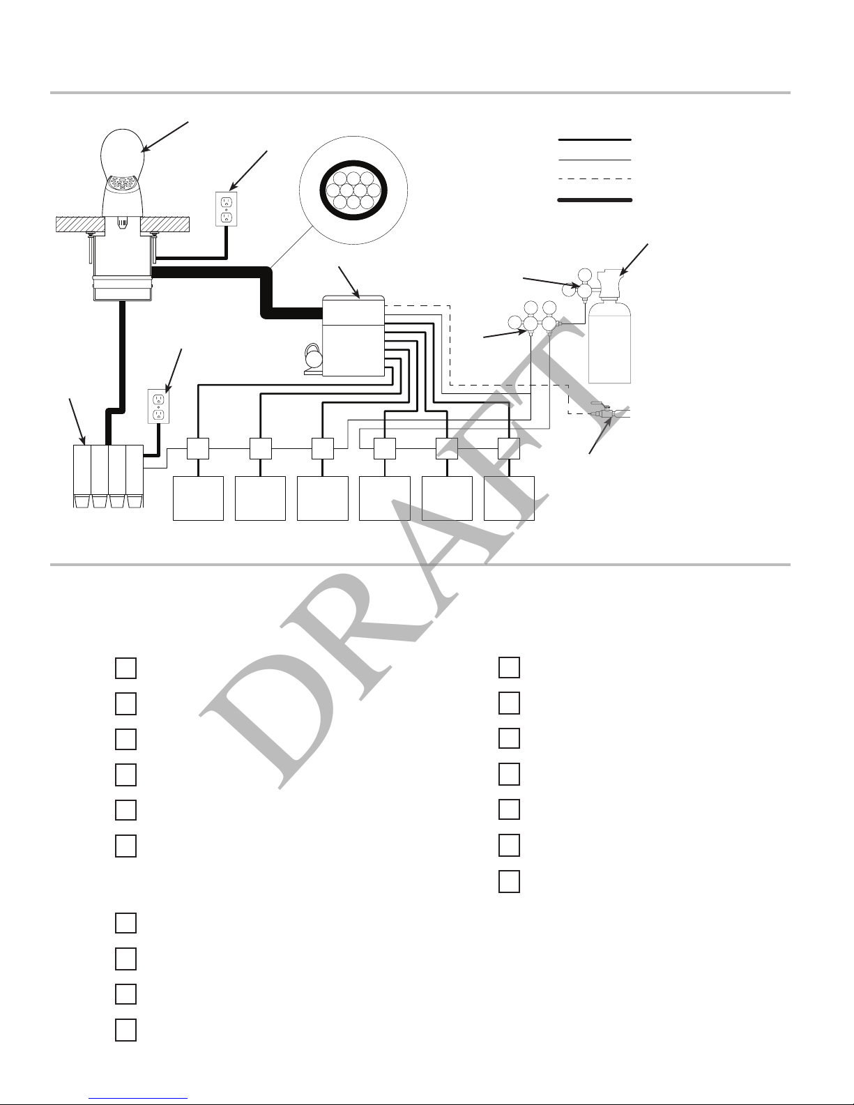
General System Overview
DRAFT
F
E
123
4 567
8910
G
E
K
H H H H HH
I I I JJ J
1. Brand Syrup 1
2. Brand Syrup 2
3. Brand Syrup 3
4. Brand Syrup 4
5. Carb Water Line
6. Carb Water Return
7. Brand Syrup 5
8. Brand Syrup 6
9. Plain Water Line
10. N/A
C
D
Syrup Line
CO2 Line
Plain Water Line
Electrical
B
A. Water Source
357575
A
B. CO2 Source
C. High Pressure CO2
Regulator
D. Low Pressure CO2
Regulator Manifold
E. Electrical Outlet
F. Tower (Dispenser)
G. Recirculation Unit
H. Syrup Pump
I. BIB Non-Diet Syrup
Containers
J. BIB Diet Syrup
Containers
K. Flavour Extension
Syrup Module
PRE-INSTALLATION CHECKLIST
TOOLS REQUIRED:
Oetiker Pliers
Tubing Cutters
Wrench
Slotted Screwdriver
Phillips Screwdriver
Drill
BIB SYSTEM:
BIB Rack
BIB Syrup Boxes
BIB Regulator Set
POST MIX ACCESSORIES:
High Pressure CO2 Regulator
Low Pressure CO2 Regulator Manifold
CO2 Supply
Chain for CO2 Tank
Beverage Dispenser
Beverage Tubing
Oetiker Clamp Fittings
BIB Connectors
5
Page 6
BEFORE INSTALLATION:
DRAFT
Do you have enough space to install the
dispenser?
CONSIDER LOCATION OF THE
FOLLOWING BEFORE THE INSTALL:
Water Supply Lines
Is the countertop level?
Can the countertop support the weight of
the dispenser?
Is dispenser located away from direct
sunlight or overhead lighting?
Electrical Outlet
Heating and Air Conditioning Ducts
Read This Manual
This manual was developed by Lancer Corporation as a reference guide for the owner/operator and
installer of this dispenser. Please read this manual before installation and operation of this
dispenser. Please see pages XX-XX for troubleshooting or service assistance. If the service cannot
be corrected please call your Service Agent or Lancer Customer Service. Always have your model
and serial number available when you call.
INSTALLATION
Unpacking the Dispenser
1. Cut package banding straps and remove.
2. Open the box and carefully remove the dispenser from
the corrugated shipping carton and place on a at surface
taking care to not scratch the plastic covers.
3. Leave the merchandiser in the box until the installation of
the dispenser is complete.
NOTE
Inspect unit for concealed damage. If evident, notify
deliveringcarrierandleaclaimagainstthesame.
! ATTENTION
DO NOT LAY UNIT ON ITS SIDE OR BACK
Selecting/Preparing a Counter Location
1. Select a location that is in close proximity to a properly
grounded electrical outlet and a water supply that meets the
requirements shown in the Specications section found on
page 4.
! ATTENTION
Inspect the counter location where the unit is to be
installed. Verify the selected counter is strong enough
to safely support the weight of the installed unit. The
ideal counter for installation should measure at least
25 mm (1 in) thick (Maximum of 60 mm, 2.36 in).
6
2. Select a location for the remote chiller system or carbonator
(if nessesary), syrup pumps, CO2 tank, product containers,
avour syrup module, and water lter (recommended).
3. Once the location for the dispenser and the remote chiller
have been determined, route the 10-line python and cut/
trim to length.
Page 7
Dispenser/Chiller Installation
DRAFT
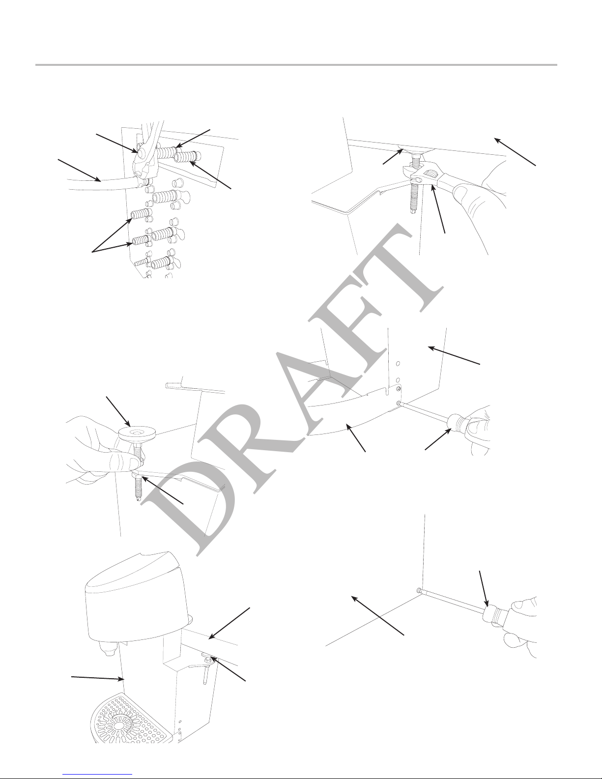
1. Connect appropriate tubing for the soda recirculation lines,
located in the 10-line python and routed from the remote
chiller, to the unit inlets. Repeat for plain water line (See the
Plumbing Diagram on page 20 for reference).
D
C
B
2. Connect appropriate tubing for all syrup lines located in the
10-line python and routed from the remote chiller, to the unit
inlets.
3. Connect appropriate tubing for all avour lines, routed from
the remote avour syrup module, to the unit inlets.
4. Once all connections to the unit have been made, loosen
the clamp nuts and lower the two (2) clamps on either side
of the unit.
A
A
A. Water Inlet
B. Syrup Inlet
C. Tubing
D. Oetiker Pliers
6. Using a wrench, raise the two (2) clamps underneath the
counter and tighten the clamp nuts to secure the unit in
place.
C
B
7. Remove the drip plate from the drip tray.
8. Remove the drip tray from the drip bracket.
9. Using a screwdriver, remove the drip bracket by unscrewing
the four (4) side screws (two (2) on each side).
A. Counter
B. Wrench
C. Clamp
A
A
B
A
5. Slide the unit onto the counter in the designated location.
A
A. Clamp Nut
B. Clamp
B
C
B
C
10. Remove the splash housing by removing the two (2) front
screws. Pull forward at the bottom of the plate to release
from the three (3) locating tabs at the top of the housing.
A
A. Unit
B. Drip Bracket
C. Screwdriver
B
A. Front of Unit
B. Screwdriver
A. Unit
B. Counter
C. Clamp
7
Page 8

11. Unscrew the key lock rod located underneath the keypad
DRAFT
and behind the nozzle.
15. Plug in power cord to power supply then route power supply
cord to the designated grounded electrical outlet.
! ATTENTION
DO NOT pull down on key lock rod, only loosen rod
enough to release the keypad.
A
A. Key Lock Rod
B. Nozzle
12. Once released, gently lift up on the front of the keypad
and slide forward to release from the two (2) locating tabs,
remove the keypad and gently set down on the bar next to
the dispenser.
A
! WARNING
DO NOT PLUG UNIT INTO GROUNDED ELECTRICAL
OUTLET AT THIS TIME. Make sure that all water lines
are tight and unit is dry before making any electrical
connections
A
B
B
A. Power Cord to Unit
B. Power Supply
NOTE
Unit is designed to be supported by a remote chiller
system or remote ice cooled system. Please see the
manufacturer’sspecicationsandinstructionsfor
installation. The following are the instructions for
plumbing the remote chiller system to the tower.
B
A. Keypad
B. Keypad Shroud
13. Remove the keypad shroud by rst removing the two
screws located underneath next to the keylock rod. Then
remove the shroud by sliding up and out and then place on
the bar next to the dispenser.
14. Reattach the keypad using the key lock rod, paying
attention to not over-tighten. This will hold the keypad in
place while setting ow rates.
16. Route appropriate tubing from the syrup pump location to
the syrup inlets at the remote chiller. Repeat for all syrup
connections.
17. Route appropriate tubing from the water source to the water
inlet at the remote chiller and only connect tubing to the
water source.
18. Turn on the water and ush the water line thoroughly.
19. Turn off the water and connect water line to the plain water
inlet at the remote chiller.
20. Route appropriate tubing from the designated CO2 source
to the CO2 inlet at the back of the remote chiller and
connect tubing to inlet.
8
Page 9

Installing Remote Syrup Pumps
DRAFT
1. Mount pump brackets in pre-determined location.
2. Mount syrup pumps to pump brackets.
B
A
C
3. Measure and cut tubing to length between the pump CO2
inlets, then connect tubing to all pumps.
A. Pump Bracket
B. Syrup Pump
C. CO2 Inlet
5. Cut tubing from CO2 supply to tee tting at syrup pumps
and install another tee tting.
6. Attach line from remote chiller CO2 inlet to tee tting
between syrup pumps and CO2 supply.
D
B
7. Connect tubing from dispenser syrup inlet to the syrup
pump outlet tting. Repeat for each syrup line/pump.
A
A. Tee Fitting
B. Line to Tee at Syrup Pump
C. Line to CO2 Supply
D. Remote Chiller CO2 Inlet
C
B
D
4. Using tubing cutters, cut any pump CO2 supply line and
install tee tting, then route appropriate tubing from the CO2
supply to the tee tting at syrup pumps.
C
B
A
C
A. Syrup Pump
B. CO2 Line
C. Fitting
D. Oetiker Pliers
A. Tee Fitting
B. Line to Syrup Pump
C. Line to CO2 Supply
D. Fitting
B
D
A
B
C
A. Syrup Pump Outlet
B. Syrup Pump
A
C. Fitting
9
Page 10

Installing CO2 Supply
DRAFT
1. Connect high pressure CO2 regulator assembly to CO2
cylinder or bulk system.
! ATTENTION
Before installing regulator, assure that a seal (washer
or o-ring) is present in regulator attachment nut.
A
C
D
B
A. CO2 Regulator
- Thread regulator nut on to tank,
then tighten nut with wrench
2. Connect a 6.35 mm (1/4 in) nut, stem and seal to high
pressure CO2 regulator outlet.
A
B. Outlet
C. Wrench
D. CO2 Supply
A
B
D
A. CO2 Regulator
C
4. Connect tubing routed from the CO2 inlet at the remote
chiller and normal, non-diet syrup pumps to one of the low
pressure CO2 regulator manifold outlets.
5. Connect tubing routed from the diet syrup pumps to the
second outlet of the low pressure CO2 regulator manifold.
B. Fitting
C. Line to CO2 Regulator
Manifold
D. Oetiker Pliers
C
D
B
C
A. CO2 Regulator
B. Wrench
C. 6.35 mm nut, Stem
D. CO2 Supply
3. Route appropriate tubing from the low pressure CO2
regulator manifold location to the 6.35 mm (1/4”) nut, stem
on the high pressure CO2 regulator attached to source and
connect tubing.
! ATTENTION
A dedicated CO2 regulator is required to supply the
CO2 to all normal, non-diet syrup pumps as well as to
all diet syrup pumps.
D
A
A. Line to Non-Diet Syrup
Pumps
B. Line to Diet Syrup Pumps
C. Line to CO2 Regulator
D. CO2 Regulator Manifold
6. Using a wrench, loosen lock nut on high pressure regulator
adjustment screw then using a screwdriver back out lock
nut screw all the way.
B
! WARNING
DO NOT TURN ON CO2 SUPPLY AT THIS TIME
7. Repeat Step 6 for both low pressure regulator adjustment
screws on the regulator manifold
10
Page 11

B
DRAFT
B
A
C
A. CO2 Regulator
B. Wrench
C. Regulator locknut
Connecting to Syrup Supply
1. Install BIB (bag in box) connectors onto the syrup pump
inlet tubing.
! ATTENTION
Use proper connector for syrup manufacturer
A
D
B
A. Syrup Pump Inlet C. BIB Connector
B. Fitting D. Oetiker Pliers
C
A
2. Connect syrup BIBs to connectors. Repeat for each syrup
line/pump and each avor injector line/pump.
A
C
B
A. CO2 Regulator
B. Screwdriver
C. Regulator Adjustment Screw
C
A. Syrup Pump Inlet
B. BIB Connector
C. BIB Syrup Container
Dispenser Setup
1. Turn on the water supply.
2. Verify all Bag-in-Box or Figal tanks contain syrup and check
for leaks.
3. Open the pressure relief valve located on the remote chiller
system by ipping up on the valve cap lever. Hold open
until water ows from the relief valve then close (ip down)
reief valve.
A
A. Carbonator Relief Valve
4. Connect power cord to grounded electrical outlet. Keypad
LEDs will ash in a sequence to validate the electronics and
congure the keypad.
! WARNING
The dispenser must be properly electrically grounded
to avoid serious injury or fatal electrical shock. The
power cord has a three-prong grounded plug. If a
three-hole grounded electrical outlet is not available,
use an approved method to ground the unit. Follow
all local electrical codes when making connections.
Each dispenser must have a separate electrical circuit.
Do not use extension cords. Do not connect multiple
electrical devices on the same outlet.
5. Locate a valve that utilizes plain water brand then close the
syrup line at the backblock for that corresponding valve.
NOTE
Example: Oasis and Schweppes Lemonade both utilize
plain water in their syrups.
11
Page 12

6. Using the keypad, select the brand whose syrup line was
DRAFT
closed in the previous step, then press and hold the pour/
cancel button until a steady ow of water is achieved.
A A
A
9. Turn on CO2 at the source then, using a screwdriver, adjust
the high pressure regulator at the source to 75 PSI (0.517
MPA) then tighten locknut with wrench.
B
A
A
A A
C
C C
E
7. Select the soda button then press and hold the pour/cancel
button until a steady ow of water is achieved.
8. Ensure that the pump deck at the remote chiller is turned off
before turning on the CO2.
B
C
D
A. Brand Buttons
B. Soda Button
C. Flavour Injector Buttons
D. Portion Control Buttons
E. Pour/Cancel Button
10. Adjust the low pressure regulator routed from the normal,
11. Adjust the second low pressure regulator routed from the
12. Select the soda button then press and hold the pour/cancel
13. Reactivate the pump deck at the remote chiller.
14. Repeat Step 12 until a steady ow of soda is achieved.
Adjust Water Flow Rate & Syrup/Water Ratio
NOTE
The refridgeration unit should have been running for at
leastone(1)hourbeforeattemptingtosetowrates
on valves. The drink temperature should be no higher
than40°F(4.4°C)whenowratesareset.Thisisbest
done after the remote chiller has already made an ice
bank.
1. Using a Lancer ratio cup verify water ow rate (5 oz. in 4
sec.) by activating the soda module. Remove the protective
cap for the corresponding valve and use a screwdriver to
adjust if needed.
2. Repeat Step 1 for the plain water brand whose syrup was
3. Open the syrup line at the backblock, closed in the previous
4. Once all the water modules have been calibrated, remove
C
non-diet syrup pumps and remote chiller to 75 PSI (0.517
MPA).
diet syrup pumps to 35 PSI (0.241 MPA).
button until gas out.
closed in the previous section.
section.
nozzle by twisting counter clockwise and pulling down.
A. Regulator Adjustment Screw
B. Adjust to 75 PSI (0.517 MPA)
C. Wrench
C
A
Increase Decrease
D
B
12
C
A. Flow Control
B. Valve Retainer
C. Solenoid
D. Valve Body
B
A
A. Nozzle
B. Clamp
C. Counter
5. Install Lancer syrup seperator (PN 82-3458) in place of
nozzle.
Page 13

B
DRAFT
A
A. Syrup Seperator
B. Counter
6. Turn off the soda and plain water backblocks.
7. Purge each syrup line by selecting the brand and pressing
the pour button, until no air is coming from the lines and a
steady ow is achieved.
8. Turn back on the soda and plain water backblocks.
Merchandiser Installation
1. Unplug power to the unit before installing the merchandiser.
2. Remove keypad from key lock rod and set on bar next to
unit.
3. Remove the merchandiser from the box.
4. Plug in the six (6) pin connector and USB cable to the main
tower.
9. Using a Lancer ratio cup, activate syrup valve and capture
a sample. Verify that the syrup level is even with the water
level. Use a screwdriver to adjust if needed.
A
B
A. Syrup Seperator
B. Ratio Cup
10. Repeat Step 8 for each brand/syrup line then remove the
syrup seperator and reinstall nozzle.
A
A
B
C
A. 6-Pin to Unit
B. 6-Pin to Merchandiser
C. Merchandiser
5. Gently slide the merchandiser onto the unit. A 4 mm (0.15
in) screw will designate the front of the main tower.
! ATTENTION
Careful not to pinch any cables or wires when
installing the merchandiser to the unit.
B
A. Merchandiser
B. Main Tower
C. Counter
6. Using a screwdriver and screws provided, attach the
merchandiser to unit.
7. Reinstall keypad shroud to unit.
8. Reattach keypad to key lock rod/keypad shroud.
9. Reinstall splash housing, drip bracket, drip tray, and drip
plate.
13
Page 14

Scheduled Maintenance
DRAFT
As Needed
Daily
Weekly
Monthly
Every Six Months
• Keep exterior surfaces of dispenser (include drip tray and drip plate) clean using a clean,
damp cloth.
• Remove outer nozzle and rinse well in warm water. DO NOT use soap or detergent. This will
cause foaming and off taste in nished product.
• Using the brush provided and cleaning solution, clean the nozzle injectors. See Cleaning and
Sanitizing Nozzle section on the next page for reference.
• Remove drip plate and drip tray and wash both in cleaning solution.
• With a clean cloth and cleaning solution, wipe off all of the unit’s exterior surfaces and splash
areas. DO NOT USE ABRASIVE SOAPS OR STRONG DETERGENTS. DO NOT USE
AMMONIA BASED PRODUCTS WHEN CLEANING THE SCREEN OR SURROUNDING
PLASTICS.
• Replace the drip plate, drip tray, and nozzle.
• Taste each product for off tastes. If off taste occurs clean and sanitize the unit using the
appropriate procedures outlined in the Cleaning and Sanitizing section of this manual.
• Check the water level in the water bath for the remote chiller (if necessary). Replenish as
required.
• Clean and sanitize the unit using the appropriate procedures outlined in the Cleaning and
Sanitizing section of this manual.
• Clean remote chiller according to manufacturer’s instructions (if necessary).
• Clean the entire exterior of the unit.
CLEANING AND SANITIZING
General Information
• Lancer equipment (new or reconditioned) is shipped from the factory cleaned and sanitized in accordance with NSF guidelines.
The operator of the equipment must provide continuous maintenance as required by this manual and/or state and local health
department guidelines to ensure proper operation and sanitation requirements are maintained.
NOTE
ThecleaningproceduresprovidedhereinpertaintotheLancerequipmentidentiedbythismanual.Ifother
equipment is being cleaned, follow the guidelines established by the manufacturer for that equipment.
• Cleaning should be accomplished only by trained personnel. Sanitary gloves are to be used during cleaning operations.
Applicable safety precautions must be observed. Instruction warnings on the product being used must be followed.
! ATTENTION
• Use sanitary gloves when cleaning the unit and observe all applicable safety precautions.
• DO NOT use a water jet to clean or sanitize the unit.
• DO NOT disconnect water lines when cleaning and sanitizing syrup lines, to avoid contamination.
• DO NOT use strong bleaches or detergents; These can discolor and corrode various materials.
• DO NOT use metal scrapers, sharp objects, steel wool, scouring pads, abrasives, or solvents on the dispenser.
• DO NOT use hot water above 60° C (140° F). This can damage the dispenser.
• DO NOT spill sanitizing solution on any circuit boards. Insure all sanitizing solution is removed from the system.
14
Page 15

Cleaning and Sanitizing Solutions
DRAFT
Cleaning Solution
Mix a mild, non-abrasive detergent (e.g. Sodium Laureth
Sulfate, dish soap) with clean, potable water at a temperature
of 32°C to 43°C (90°F to 110°F). The mixture ratio is one
ounce of cleaner to two gallons of water. Prepare a minimum of
ve gallons of cleaning solution. Do not use abrasive
cleaners or solvents because they can cause permanent
damage to the unit. Ensure rinsing is thorough, using clean,
potable water at a temperature of 90°F to 110°F. Extended
lengths of product lines may require additional cleaning solution.
Sanitizing Solution
Prepare sanitizing solutions in accordance with the
manufacturer’s written recommendations and safety guidelines.
The solution must provide 50 to 100 parts per million (PPM)
chlorine (e.g. Sodium Hypochlorite or bleach). A minimum of ve
gallons of sanitizing solution should be prepared. Any sanitizing
solution may be used as long as it is prepared in accordance
with the manufacturer’s written recommendations and safety
guidelines, and provides 50 to 100 parts per million (PPM)
chlorine.
! CAUTION
If a powder sanitizer is used, dissolve it thoroughly with hot water prior to adding to the product system. Ensure
sanitizing solution is removed from the dispenser as instructed.
Cleaning and Sanitizing Product Lines
1. Disconnect product lines from BIB’s or other product supply.
2. Place product lines, with BIB connectors, in a bucket of
warm water.
3. Activate each valve to ll the lines with warm water and
ush out product remaining in the lines.
4. Prepare Cleaning Solution described above.
5. Place product lines, with BIB connectors, into cleaning
solution.
6. Activate each valve until lines are lled with cleaning
solution then let stand for ten (10) minutes.
7. Flush out cleaning solution from the syrup lines using clean,
warm water.
8. Prepare Sanitizing Solution described above.
9. Place product lines into sanitizing solution and activate
each valve to ll lines with sanitizer. Let sit for ten (10)
minutes.
10. Reconnect product lines to BIB’s and draw drinks to ush
solution from the dispenser.
11. Taste the drink to verify that there is no off-taste. If off-taste
is found, ush product system again.
! CAUTION
Following sanitization, rinse with end-use product
until there is no aftertaste. Do not use a fresh water
rinse. This is a NSF requirement. Residual sanitizing
solution left in the system creates a health hazard.
Cleaning and Sanitizing Nozzle
1. Disconnect power, so as to not activate valve while
cleaning.
2. Remove outer nozzle by twisting counter clockwise and
pulling down.
C
A
A. Nozzle
B. Clamp
C. Counter
3. Rinse nozzle with warm water.
4. Wash nozzle with cleaning solution then immerse in
sanitizing solution and let sit for fteen (15) minutes.
5. Set nozzle aside and let air dry. DO NOT rinse with water
after sanitizing.
6. Using the brush provided and cleaning solution, clean the
nozzle injectors.
B
B
A
A. Nozzle Injectors
B. Nozzle Brush
C. Counter
D. Clamp
7. Using the brush provided, sanitize the nozzle injectors and
let air dry.
8. Reconnect nozzle.
C
D
15
Page 16

9. Connect power.
DRAFT
10. Taste the drink to verify that there is no off-taste. If off-taste
is found, sanitize the nozzle and nozzle injectors again.
! CAUTION
Following sanitization, rinse with end-use product
until there is no aftertaste. Do not use a fresh water
rinse. This is a nsf requirement. Residual sanitizing
solution left in the system creates a health hazard.
TROUBLESHOOTING
TROUBLE CAUSE REMEDY
Miscellaneous leakage. 1. Gap between parts.
2. Damaged or improperly installed o-rings.
Insufcient water ow. 1. Insufcient incoming supply water
pressure.
2. Shutoff on mounting block not fully open.
3. Foreign debris in water ow control.
4. Foreign debris in water pump strainer
Insufcient product ow. 1. Insufcent CO2 pressure to BIB pumps.
2. Out of CO2 .
3. Shutoff on mounting block not fully open.
4. Foreign debris in product ow control.
5. Bad product pump.
Erratic ratio. 1. Incoming water and/or product supply not
at minimum owing pressure.
2. Foreign debris in water and/or product ow
controls.
1. Tighten appropriate retaining screws
2. Replace or adjust appropriate o-rings
1. Verify incoming supply water pressure is a
minimum of 25 PSI (0.172 MPA).
2. Open shutoff fully.
3. Remove water ow control from upper
body and clean out any foreign material to
ensure smooth free spool movement.
4. Remove water pump strainer and clean.
1. Adjust CO2 pressure to 80 PSI (0.550
MPA) [minimum 70 PSI (0.480 MPA)] for
BIB pumps.
2. Replace CO2 tank/rell.
3. Open shutoff fully.
4. Remove product ow control form upper
body and clean out any foreign material to
ensure smooth free spool movement.
5. Replace BIB pump.
1. Check pressure and adjust
2. Remove ow controls from upper body and
clean out any foreign material to ensure
smooth free spool movement.
No product dispensed 1. Water and product shutoffs on mounting
block not fully open.
2. The key switch on an electric valve is in
the OFF position.
3. Electric current not reaching valve.
4. Improper or inadequate water or product
supply.
5. Transformer Failure
6. Bad valve solenoid(s)
16
1. Open shutoff fully.
2. Turn key switch to ON position.
3. Check electric current supplied to valve.
If current is adequate, check solenoid coil
and switch, and replace if necessary.
4. Remove valve from mounting block and
open shutoffs slightly and check water and
syrup ow. If no ow, check dispenser for
freeze-up or other problems
5. Reset transformer circuit breaker. If
breaker trips again check for pinched wire
harness at backblocks
6. Replace Solenoid(s)
Page 17

TROUBLE CAUSE REMEDY
DRAFT
Water only dispensed; no
product; or product only
dispensed, no water
Syrup only dispensed. No
water, but CO2 gas dispensed
with syrup.
Excessive foaming. 1. Incoming water or syrup temperature too
1. Water or product shutoff on mounting block
not fully open.
2. Improper or inadequate water or product
ow.
3. BIB supply too far from dispenser.
4. CO2 pressure too low.
5. Stalled or inoperative BIB pump
6. Kinked line.
1. Improper water ow to dispenser.
2. Carbonator pump motor has timed out.
high.
2. CO2 pressure too high.
3. Water ow rate too high.
4. Nozzle and diffuser not installed.
5. Nozzle and diffuser not clean.
6. Air in BIB lines.
7. Poor quality ice.
8. High beverage temperature.
1. Open shutoff fully.
2. Remove valve from mounting block, open
shutoffs slightly and check water and
syrup ow. If no ow, check dispenser for
freeze-up or other problems. Ensure BIB
connection is engaged.
3. Check that BIB supply is within six (6) feet
of the dispenser.
4. Check the CO2 pressure to the pump manifold to ensure it is between 70 and 80 PSI
(0.483 and 0.552 MPA).
5. Check CO2 pressure and/or replace pump.
6. Remove kink or replace line.
1. Check for water ow to dispenser (see
Insufcient Water Flow on previous page).
2. Reset by turning the unit OFF and then
ON.
1. Correct prior to dispenser. Consider larger
dispenser or pre-cooler.
2. Adjust CO2 pressure downward, but not
less than 70 PSI.
3. Re-adjust and reset ratio. Refer to “Adjust
Water Flow Rate & Syrup/Water Ratio”
Section.
4. Remove and reinstall properly.
5. Remove and clean.
6. Bleed air from BIB lines.
7. Check quality of ice used in drink.
8. Check refrigeration system.
Warm drinks. 1. Restricted airow.
2. Dispenser connected to hot water supply.
3. Dispenser capacity exceeded.
BIB pump does not operate
when dispensing valve opened.
BIB pump operated, but no
ow.
BIB pump continues to operate
when bag is empty.
1. Out of CO2, CO2 not turned on, or low CO2
pressure.
2. Out of syrup.
3. BIB connector not tight.
4. Kinks in syrup or gas lines.
5. Bad BIB Pumps.
1. Leak in syrup inlet or outlet line.
2. Defective BIB pump check valve.
1. Leak in suction line.
2. Leaking o-ring on pump inlet tting.
1. Check clearances around sides, top, and
inlet of unit. Remove objects blocking
airow through grill.
2. Switch to cold water supply.
3. Add pre-cooler or replace with larger
dispenser.
1. Replace CO2 supply, turn on CO2
supply, or adjust CO2 pressure to 70-80
PSI (0.483-0.552 MPA)
2. Replace syrup supply.
3. Fasten connector tightly.
4. Straighten or replace lines.
5. Replace BIB pump.
1. Replace line.
2. Replace BIB pump
1. Replace line.
2. Replace o-ring.
17
Page 18

TROUBLE CAUSE REMEDY
DRAFT
BIB pump fails to restart after
bag replacement.
BIB pump fails to restart when
dispensing valve is closed.
No product out light. 1. Burned-out lamp
Low or no carbonation. 1. Low or no CO2.
1. BIB connector not on tight.
2. BIB connector is stopped up.
3. Kinks in syrup line
4. Bad BIB Pumps.
1. Leak in discharge line or ttings.
2. Empty BIB.
3. Air leak on inlet line or bag connector.
2. Faulty wiring or pressure switch in product
line.
2. Excessive water pressure.
3. Worn or defective carbonator pump.
1. Tighten BIB connector.
2. Clean out or replace BIB connector.
3. Straighten or replace line.
4. Replace BIB pump.
1. Repair or replace discharge
2. Replace BIB.
3. Repair or replace.
1. Replace lamp.
2. Repair or replace.
1. Check CO2 supply. Adjust CO2 pressure to
70 PSI (0.483 MPA).
2. Water regulator should be set at 50 PSI
(0.345 MPA)
3. Replace carbonator pump.
Dispenser Disposal
To prevent possible harm to the environment from improper disposal, recycle the unit
by locating an authorized recycler or contact the retailer where the product was purchased.
18
Comply with local regulations regarding disposal of the refrigerant and insulation.
Page 19

ILLUSTRATIONS AND PART LISTINGS
DRAFT
Main Unit Assembly
Item Part No. Description
1 TTCOS-012 MPUpLeg
2 VVSyrupVAssem
3 TTCOS-030 SodaReCirc Assem
4 TTCOS-022 WaterPipeTT
5 TTCOS-007 SplashHousing
6 BonusValveFlipAssem
7 TTCOS-013 ClampBracePlate
8 TTCOS-016 Valve_Bracket
10 TTCOS-008 NewDripBracket
11 TTCOS047 BottomCoverSheet
12 TTCOS-017 WorkTopValveBoxx2BF
13 FoamInsuBlock
14 Valve_InterfaceModule
15 TTCOS-018 Valve_PCB_Bracket
16 TTCOS-005 TTNozzleBracket
17 NozzleAssem
18 TTCOS-015 metal-base-prole-051114
Item Part No. Description
19 1_4syrupLine
20 TTCOS-034 TT_Drip_Plate
21 M4_12mm_PanHead
22 TTCOS-048 ccbb-drip-tray
23 3_8_Elbow_BB
24 3_8_Straight_BB
25 TTCOS-027 Key_Lock_Rod
26 TTCOS-023 Locking Nut
27 Locking Rod O’ Ring
28 TTCOS-030 Soda_Noz_Pipe_Assem
29 SSyrupElbow
30 1_4_Straight_BB
31 TTCOS-035 CupStop
32 ISO 7045 - M4 x 5 - Z -- 5N
33 TTCOS-044 ccbb-external-parts-020315
34 TTCOS-046 RubberFootPad
35 Clamp M8 Locking Bolt
36 TTCOS-015 New_KeyGuide_Plate
19
Page 20

Unit Plumbing Diagram
DRAFT
B1
B2
B3
F3
SR
PW
B4
B5
B6
F1
Item Description
B1 Brand Syrup 1
B2 Brand Syrup 2
B3 Brand Syrup 3
B4 Brand Syrup 4
B5 Brand Syrup 5
B6 Brand Syrup 6
F1 Flavour Injector 1
F2 Flavour Injector 2
F3 Flavour Injector 3
F4 Flavour Injector 4
PW Plain Water Line
SR Soda Recirculation
SD Soda Line
F4
B6
F1
B1
F2
B4
F2
B3
B2
SD
B5
F4
F3
20
Page 21

Unit Wiring Diagram
DRAFT
21
Page 22

Lancer Corp.
800-729-1500
Technical Support/Warranty: 800-729-1550
custserv@lancercorp.com
lancercorp.com
 Loading...