


ADX-2400D
AUDIO
DISTRIBUTION AND DELAY
SYSTEM
(AES Digital I/O)
Installation and Operation Manual
Software Version 1.3
October, 2007
Lance Design / 27 Fairview Avenue / Ridgefield, Connecticut 06877
Tel: 203-894-8206 / Fax: 203-894-8207
www.lancedesign.com
WARRANTY STATEMENT
This equipment is warranted to be free of defects in materials and workmanship for
a period of two years from date of delivery. Any necessary repairs resulting from
defects in materials or in manufacture will be made free of charge provided that the
equipment has not been subjected to mechanical or electrical abuse, or modification,
as determined by Lance Design, and also that the equipment is returned to Lance
Design with prior authorization.
No liability whatsoever is assumed for consequential damages resulting from the use
or failure of this equipment. This warranty is in lieu of all other warranties,
expressed or implied, including any implied warranty of fitness for purpose.
COPYRIGHT
All software and hardware designs are copyrighted to Lance Design, 2006-7.
CAUTION! HAZARDOUS VOLTAGES ARE EXPOSED WHEN THE TOP
COVER OF THE RACK FRAME IS REMOVED. DO NOT APPLY POWER
WITH THE UNIT DISASSEMBLED.
2
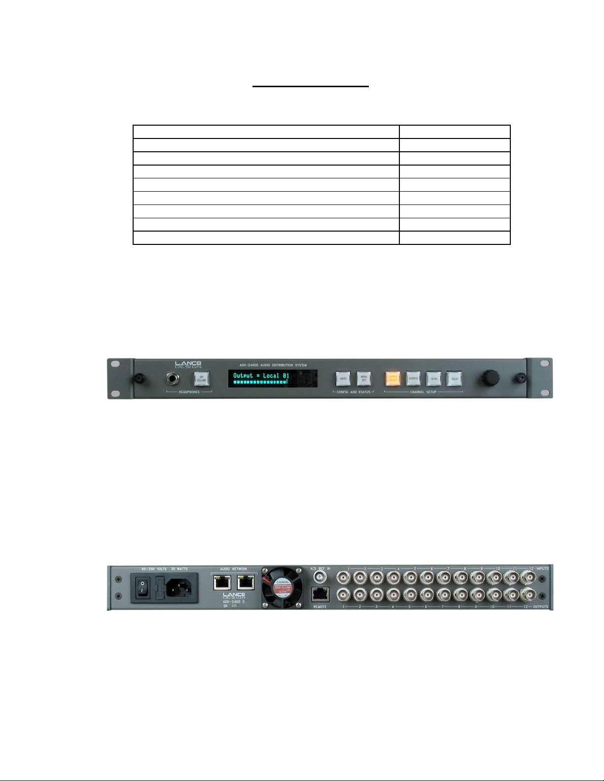
Table of Contents
Quick Operation Guide Page 4
Menu Items Page 5
Saving and Recalling Configurations Page 8
Locking Setups and Menus [options dipswitch] Page 8
General Operation Page 9
Audio Network Page 10
Designing the Network [Important Information] Page 12
Installation Page 15
Specifications Page 16
Front Panel View
Rear Panel View
3

QUICK OPERATION GUIDE
To Select Output Channel (or Channels) to Adjust
Press ‘OUTPUT SELECT’ button, and turn knob until desired channel is selected.
The order of the channel selection is as follows:
Local (AES) Output 1 through 24 (Individual Outputs)
Local Outputs 1-8 (Group)
Local Outputs 9-16 (Group)
Local Outputs 17-24 (Group)
All Local Outputs (Group)
Net (Transmitted to Ethernet) Output 1 through 24 (Individual Outputs)
Net Outputs 1-8 (Group)
Net Outputs 9-16 (Group)
Net Outputs 17-24 (Group)
All Net Outputs (Group)
The VU Meter and Headphone Jack will follow the output selection.
Note that if a group of outputs is selected, any setup adjustments (source, level,
delay) will be applied to all output channels within that group.
Also if a group is selected, there will be no VU display or headphone output.
To Select Source (for current output or group of outputs)
Press 'SOURCE' button. It will light, and the currently-selected source for the
selected output will be displayed. The sources available for each output are as
follows, and can be selected by turning the knob.
SILENCE The output will be muted
LOCAL INPUT The output will be fed by the corresponding local AES input
NET INPUT The output will be fed by the corresponding network receiver
888HZ TONE The output will be fed by the internal 888 Hz tone generator
560 HZ TONE The output will be fed by the internal 560 Hz tone generator
You may enable a ‘stereo summing’ mode by selecting any of the following choices,
which follow the above sources in the menu list. In these modes, the selected
source will be combined with the selected source for the other channel in the
even/odd pair; e.g., channels 1 and 2, channels 3 and 4, etc. When a ‘something +
mix’ source is selected, the mixed signal is reduced by 6 dB.
SILENCE + MIX The output will silence mixed with the other channel of the pair
LOCAL + MIX The local AES input mixed with the other channel of the pair
NET INPUT + MIX The network receiver mixed with the other channel of the pair
888HZ TONE 888Hz tone mixed with the other channel of the pair
560 HZ TONE 560Hz tone mixed with the other channel of the pair
4

To Adjust Level (for current output or group of outputs)
The output level can be adjusted in 0.25 dB increments. Maximum gain is +12 dB.
To adjust, press the 'LEVEL' button, and turn the knob.
To Adjust Delay (for current output or group of outputs)
The delay of each output can be independently adjusted from zero delay through
680 milliseconds, which corresponds to more than 20 frames at 30 frames/sec. The
delay is adjusted by first pressing the 'DELAY' button, then turning the knob to
adjust. Note that the displayed units (milliseconds or frames) is selected in the
menu.
To Adjust Headphone Volume
Press the 'HP VOLUME' button, and turn the knob. The bar graph display will show
the knob 'position'.
To Configure Menu Items
The system has several configuration items which may be set by using the menu
function. Press the 'MENU SELECT' button to enable the menu function. Turn the
knob to select the desired menu item, then press the 'MENU SET' button. Turning
the knob will now change the parameter for this item. When the desired selection is
made, you can exit the MENU SET mode by pressing any other button. (See
section on menu items below).
MENU ITEMS
Item 01 – RX 1-8 Bundle (000-999)
Packet assignment for network receiver 1, which corresponds to audio channels (net
inputs) 1-8. This number should be set to match the bundle number of the
transmitter in another unit which is sending audio to this receiver. Note that bundle
000 is inactive (off). Bundles 001-255 are broadcast bundles, and should only be
used if one transmitter is sending to more than one receiver. Bundles 256-999 are
unicast bundles, and should be used for normal point-to-point, one transmitter/one
receiver operation.
Item 02 – RX 9-16 Bundle (000-999)
Packet assignment for network receiver 2, which corresponds to audio channels (net
inputs) 9-16.
Item 03 – RX 17-24 Bundle (000-999)
Packet assignment for network receiver 3, which corresponds to audio channels (net
inputs) 17-24.
5
 Loading...