

Lance TDC-100 Installation And Operation Manual

TDC-100
TD’S DISK CONTROLLER
Installation and Operation Manual
Software Version 3.4
September 2007
Lance Design / 27 Fairview Avenue / Ridgefield, Connecticut 06877
Tel: 203-894-8206 / Fax: 203-894-8207
www.lancedesign.com

WARRANTY STATEMENT
This equipment is warranted to be free of defects in materials and workmanship for
a period of two years from date of delivery. Any necessary repairs resulting from
defects in materials or in manufacture will be made free of charge provided that the
equipment has not been subjected to mechanical or electrical abuse, or modification,
as determined by Lance Design, and also that the equipment is returned to Lance
Design with prior authorization.
No liability whatsoever is assumed for consequential damages resulting from the use
or failure of this equipment. This warranty is in lieu of all other warranties,
expressed or implied, including any implied warranty of fitness for purpose.
COPYRIGHT
All software and hardware designs are copyrighted to Lance Design,1999-2007.
CAUTION! HAZARDOUS VOLTAGES ARE EXPOSED WHEN THE TOP
COVER OF THE RACK FRAME IS REMOVED. DO NOT APPLY POWER
WITH THE UNIT DISASSEMBLED.
2
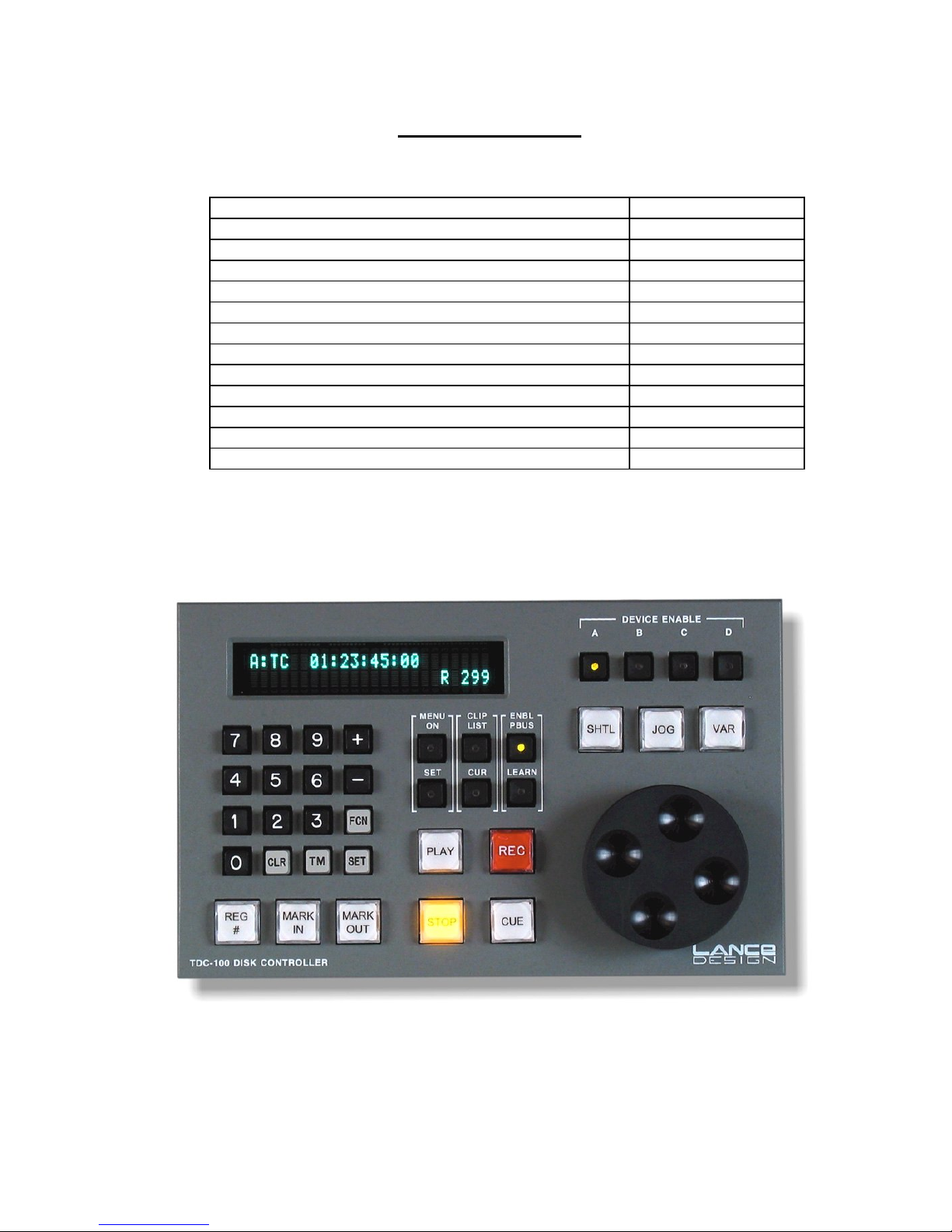
Table of Contents
Quick Operation Guide Page 4
General Description Page 7
Control Panel Description Page 7
Menu Items Page 9
General Operation Page 14
Trigger Function Numbers Page 15
Multi-Device Control Rules Page 17
Auto-dub From VTR Page 18
Multi-Point Loops Page 19
TBC Adjustment Control Page 20
Installation Page 21
GPI Inputs and Outputs Page 22
Dipswitch Functions and Connector Pinouts Page 22
3

QUICK OPERATION GUIDE
To enable a device press the corresponding ‘device enable’ button
To enable more than one device, press multiple ‘device enable buttons at the
same time. The first one pressed will be the displayed machine, and will flash
To manually learn the ‘device enable’ data (gang) into the current register, select
the devices as above, and while still holding the ‘device enable’ buttons down, press
SET on the keypad. The display will say “Now Enabled: XXXX”, indicating the
enabled machines for this register.
To select a register, press REG #, then enter three digits on the keypad (000-299).
You can also press and hold the REG # key, and use the ‘+’ and ‘-’ keys to scroll
through the registers. The register number is indicated in the lower right corner of
the display.
To clear the current register, press and hold the REG # key, and press CLR. The
display will say ‘Register Cleared’. This clears all data from the current register.
To clear ALL registers (or a group of registers), press and hold the REG# button,
the MARK IN button, and the MARK OUT button at the same time (3 buttons at
once). The display will say ‘CLR To Clear All!’. If you press the CLR key (while
holding down the above three buttons) the TDC-100 will start clearing registers at
the current register, and ascending until you either press the STOP button, or it
reaches the last register (299). This operation is deliberately awkward in order to
minimize the chance of doing it accidentally. This function may be inhibited by
turning on Dipswitch #1 on the rear of the rack mount frame.
To copy the current register to another, press REG #, then SET. The display will
say “Copy Reg To?”. Enter three digits for the destination register. All register data
will be copied from the current register to the new register.
To mark an in time, press MARK IN. All enabled machines will be marked from
their current time code (or timer) values.
To mark an out time, press MARK OUT.
To enter an in or out time from the keypad, key in the time, press SET, and press
MARK IN (for in time) or MARK OUT (for out time). Note: if multiple machines are
selected, the time will be entered only on the currently-displayed machine. The
others will not be affected.
(continued)
4

Quick Operation Guide - continued
To recall an in or out time to the display, press FCN, then MARK IN or MARK
OUT. The corresponding time value will be recalled to the display and the
scratchpad register, so you can do arithmetic with it if desired (add and subtract). If
you ‘double-click’ the REG # button it will recall the in time of the current register (or
clip name), for the currently-displayed machine. If there is no value stored in the
register, the display will be all asterisks, indicating no value.
To recall the stored clip name to the display, press FCN, then REG #. If there is
a stored clip name for the current device, it will be recalled to the second line of the
display, for the purpose of checking it.
To Trim an in time, recall time to display as above (FCN, MARK IN), press ‘+’ or ‘-’,
enter the trim value on the keypad, press SET, and press MARK IN to resave it.
Outtimes work the same way, with the MARK OUT key. You can set a known clip
duration the same way: recall the in time, press ‘+’, enter the desired duration, press
‘SET’, press ‘Mark Out’. This takes the in time, adds a duration value to it, and
stores it in the out register.
To display the duration of a register (difference between in point and out point),
press TM key. If either of the registers is clear, the display will be all asterisks,
indicating no value.
To manually learn a speed preset hold down the VAR button and press SET.
The display will confirm that the speed has been learned. This speed will be recalled
when the register is recalled. If you do a learn from the switcher, the current var
speed will be learned into the register.
To Cue Directly to a Keyed-In Time Value enter the time value on the keypad,
press ‘SET’, and press ‘CUE’. The device will cue to the entered time. The time
value will not be stored anywhere. Remember that you must press ‘SET’ before
pressing ‘CUE’. This validates the keypad entry before attempting to send the
machine to that position.
To Adjust TBC Levels press ‘FCN’, then ‘MENU’. This will put the controller into
the TBC adjust mode. Use the ‘+’ and ‘-’ keys to select the function, and the knob to
adjust. To exit this mode, press ‘FCN’ then ‘MENU’ again. The MENU button will
flash when in the TBC adjust mode. If there is no number value displayed after the
function, then the selected device does not support these commands.
(continued)
5

Quick Operation Guide – continued
To Do a Loop Play define the loop by entering an inpoint and an outpoint. The
minimum duration is 1:15 [one and one-half seconds]. The loop play may be
initiated by either Pbus trigger 5, or by pressing <FCN> the <PLAY> on the front
panel. You may simulate the Pbus trigger by pressing <FCN>, then <5> on the
keypad. The loop will run until either a STOP, RECUE or RECALL command is
received. If you turn on LOOP PRESERVE in the menu, only a STOP command
will halt the loop. You can recall another register without disturbing the loop
playback.
To Do a Multi-point Loop Play set the initial start point in the inpoint of a register
number between 000 and 099 (first 100 registers). You may also set an outpoint if
desired, although it isn’t required. The ‘inner loop’ points should be entered in a
register 100 higher. For example, if your ‘outside points’ are in register 25, your
‘inside points’ should be in register 125. Minimum duration for the inside loop is one
and one-half seconds. The multi-point loop play may be initiated by Pbus trigger 8,
or from the front panel by pressing <FCN>, then <8>. The ddr will start at the initial
start point, then loop between the ‘inner loop’ points. If you send a Pbus trigger 9
[<FCN> <9> from the keypad], the controller will stop looping at the first opportunity,
and play to the ‘outside’ outpoint [register 25 outpoint in the above example].
To Do an Automatic Transfer (Dub) from a vtr: Set inpoints for both the vtr
(playback) and the ddr (record) channels. Press and hold the device button for the
ddr, then press the vtr’s device button. Both should be lit, with the ddr’s button
flashing. This is the recorder. Press <FCN>, then <REC>. The vtr will cue back 3
seconds from the inpoint and roll. The ddr will go into record at the proper time.
To Add an Offset to All Registers first select the register number where you’d like
to start [usually 000], and select the channels you want to modify [A, B, C, D] by
lighting up the device buttons. Press <FCN>, then <TM>. The controller will
prompt you to ‘Enter Offset Time’. Enter the time using the keypad. If you want to
offset by a negative number, enter a minus sign first. Press <SET>, then <TM>.
The TDC will start modifying both the inpoints and outpoints of all selected channels.
You can stop the process by pressing STOP.
To Display Pbus Data for diagnostic purposes, turn on Item 30 in the menu, PBUS
DATA DISPLAY. This will cause the ASCII Pbus data to be displayed on line two
of the panel. If the Pbus data is incorrectly formatted (invalid command) a ‘Pbus
Format Error’ message will be displayed. Note that this menu item is turned off each
time the TDC-100 is powered up.
6

GENERAL DESCRIPTION
The Lance Design TDC-100 is designed to provide control of multiple channels of
video disk recorder(s) or other devices via P-Bus II interface to Grass Valley Group,
Sony, or other production switchers.
This combination allows the user to do the following:
1) Mark playback inpoints when learning an emem effect on the switcher.
2) Recall (cue) the playback device to these cues when effects are recalled.
3) Trigger (roll) the playback device in response to an emem timeline run, loop, or
other trigger.
In addition to these functions which are driven from the production switcher, the
control panel provides full manual control of the devices, providing normal shuttle,
jog, variable play, record, cue, and other commands.
CONTROL PANEL DESCRIPTION
The TDC-100 control panel provides the following controls (left to right on the panel):
Numeric Keypad - for entry of numeric data, register numbers, timecodes, etc.
Plus and Minus Keys - for timecode arithmetic, and for use as up/down keys for
scrolling through the menu items.
FCN Key - for selecting alternate functions of some keys. Press and release the
FCN key, then press the key whose alternate function you want.
SET Key - operates like an ‘equals’ or ‘enter’ key. To enter a timecode number
from the keypad, for example, you would key in the time, press SET, and press
MARK IN. The SET key tells the controller to use the keypad time instead of
marking from the current disk position
TM Key - used for displaying durations of registers (outpoint minus inpoint). If
you have both an inpoint and outpoint set, pressing TM will show you the duration
between them. This key is also used to enter time values into the timer or timecode
generator of the controlled device, if this capability is supported.
CLR Key - Clear function. Clears numeric entry and other modes. Functions
somewhat like a ‘cancel’ or ‘escape’ key. Also used to clear registers - see below.
7

REG# - used to select the active register from the 300 available registers. Press
this key (it lights), and enter a 3-digit register number on the keypad. The active
register number is displayed in the lower right corner of the display as ‘R 299’, for
example. This key is also used to clear a register (all inpoints and outpoints). Hold
the ‘REG #’ key down and press ‘CLR’. The current register will be cleared.
MARK IN - pressing this key will put the current disk timecode into the IN
register, for all enabled devices. Pressing this key after pressing SET will put the
keyed-in timecode value into the IN register (for the displayed device only).
Pressing FCN, then MARK IN will recall the current in time to the display. The
MARK IN button will be lighted when ever there is an inpoint stored. If the inpoint is
cleared, the button will be dark. If CLIP STORE/RECALL is on in the menu, and
there is a timecode inpoint but no clip name stored in the regitser, the MARK IN
button will flash. This serves as an indicator of the missing clip name.
MARK OUT - same as above for outpoints.
MENU ON - turns on and off the menu mode. Menu items are displayed on the
lower line of the display. Use the knob or the +/- keys to scroll through the items.
Also selects the TBC Adjust function if pressed after the “FCN” key. In this mode,
the menu button light will flash.
MENU SET - used to change the menu items. Pressing this key will toggle the
menu choices if there are only two. If there are more than two, it will step through
them. If you hold this key down, you can use the knob to adjust the menu setting.
CLIP LIST - used to display the clip directory of the disk recorder. If supported
by the disk recorder, the clip names present will be displayed. The numbers on the
left side of the display provide an index, for example 04/12 means this is clip 4 of 12.
The names can be scrolled via the +/- keys or the knob.
CUR CLIP - Loads the displayed clip, when “Clip List” above is active.
ENBL PBUS - when this key is lighted, PBUS control from the production
switcher is enabled. If not lighted, control is inhibited. This button will flash each
time a valid Pbus command is received. If it’s off, it will flash on. If it’s on, it will
flash off.
ENBL LEARN - when this key is lighted, the LEARN function from the production
switcher is active; that is, when an emem effect is learned on the switcher, the disk
inpoints will be marked from the current positions. If you have the disk inpoints set,
and don’t want to mark them each time you learn an emem, you can turn this
function off (key dark). Recall and Trigger functions are not affected. The ENBL
PBUS (above) must be on for this function to operate.
PLAY, RECORD, STOP, CUE, SHTL, JOG, VAR - standard transport controls.
When in variable mode, the speed is displayed in the upper right corner of the
display. When pressed by itself, the REC button will put the device into EE mode.
Pressing REC again, or pressing STOP will cancel EE mode. The REC button
flashes to indicate that the device is in EE mode.
8
 Loading...