

Lance ADX-2400M Installation And Operation Manual

ADX-2400M
AUDIO
DISTRIBUTION AND DELAY
SYSTEM
(MADI Digital I/O)
Installation and Operation Manual
Software Version 1.0
May, 2015
Lance Design / 27 Fairview Avenue / Ridgefield, Connecticut 06877
Tel: 203-894-8206 / Fax: 203-894-8207
www.lancedesign.com

WARRANTY STATEMENT
This equipment is warranted to be free of defects in materials and workmanship for
a period of two years from date of delivery. Any necessary repairs resulting from
defects in materials or in manufacture will be made free of charge provided that the
equipment has not been subjected to mechanical or electrical abuse, or modification,
as determined by Lance Design, and also that the equipment is returned to Lance
Design with prior authorization.
No liability whatsoever is assumed for consequential damages resulting from the use
or failure of this equipment. This warranty is in lieu of all other warranties,
expressed or implied, including any implied warranty of fitness for purpose.
COPYRIGHT
All software and hardware designs are copyrighted to Lance Design, 2006-15.
CAUTION! HAZARDOUS VOLTAGES ARE EXPOSED WHEN THE TOP
COVER OF THE RACK FRAME IS REMOVED. DO NOT APPLY POWER
WITH THE UNIT DISASSEMBLED.
2
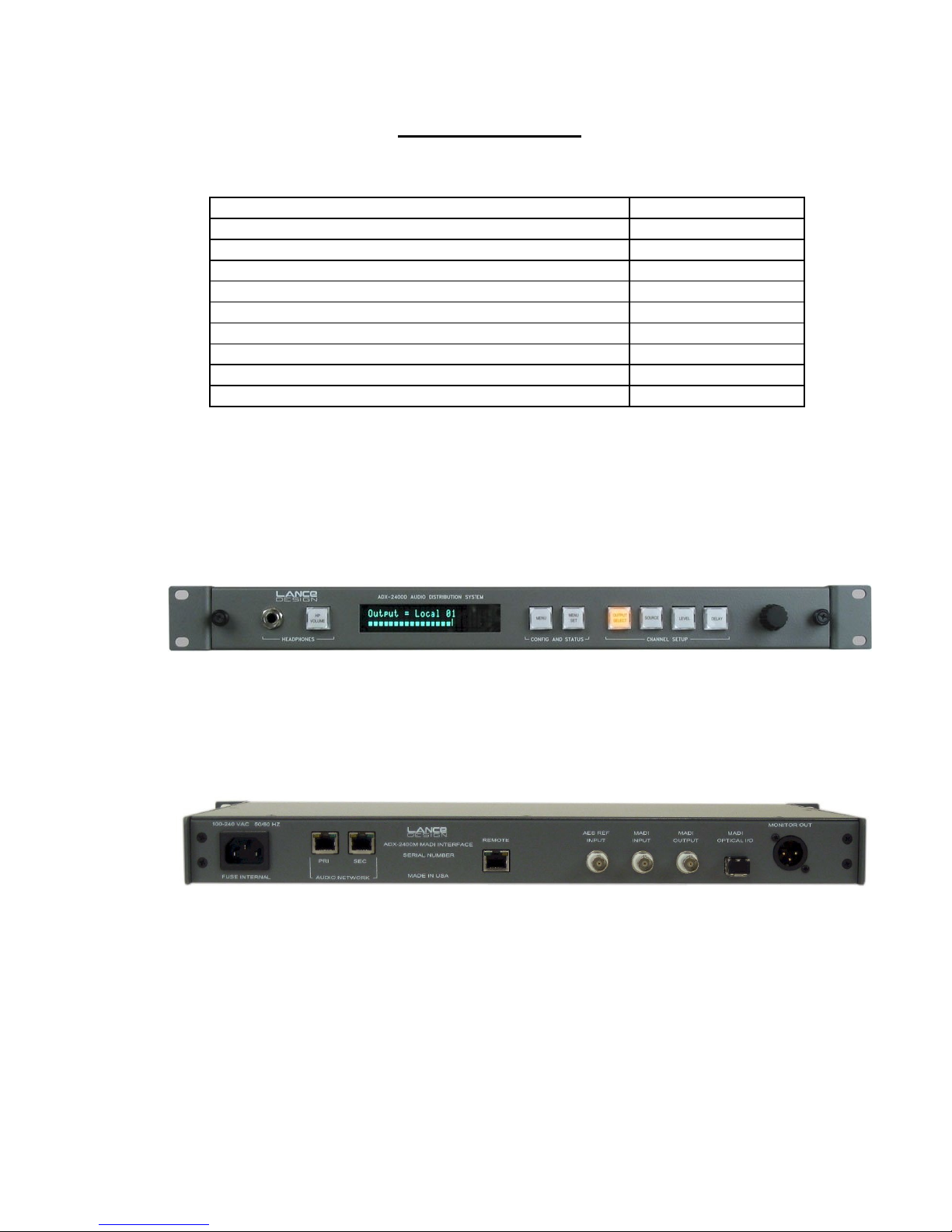
Table of Contents
Quick Operation Guide - Normal Mode Page 6
Menu Items - Normal Mode Page 7
Saving and Recalling Configurations Page 13
Locking Setups and Menus [options dipswitch] Page 13
Quick Operation Guide - Announce Booth Mode Page 14
Menu Items - Announce Booth Mode Page 15
System Configuration - Announce Booth Mode Page 19
Designing the Network [Important Information] Page 23
Installation Page 28
Specifications Page 30
Front Panel View
Rear Panel View
3
SELECTING OPERATING MODE
The ADX-2400M can operate in two distinct modes:
NORMAL mode is used for general-purpose transmission and distribution
The
applications. In this mode the units offer 24 channels of transmission in both directions,
using standard-latency Cobranet format transmission. The ADX-2400M in this mode
transmits three bundles of eight channels each, and receives three bundles of eight
channels each.
Bundle numbers are set manually from the front panel menus.
The DSPs in the unit are used for level control, source selection, and delay.
Transmission latency is approximately 7 milliseconds in each direction (standard mode see next page for low-latency information).
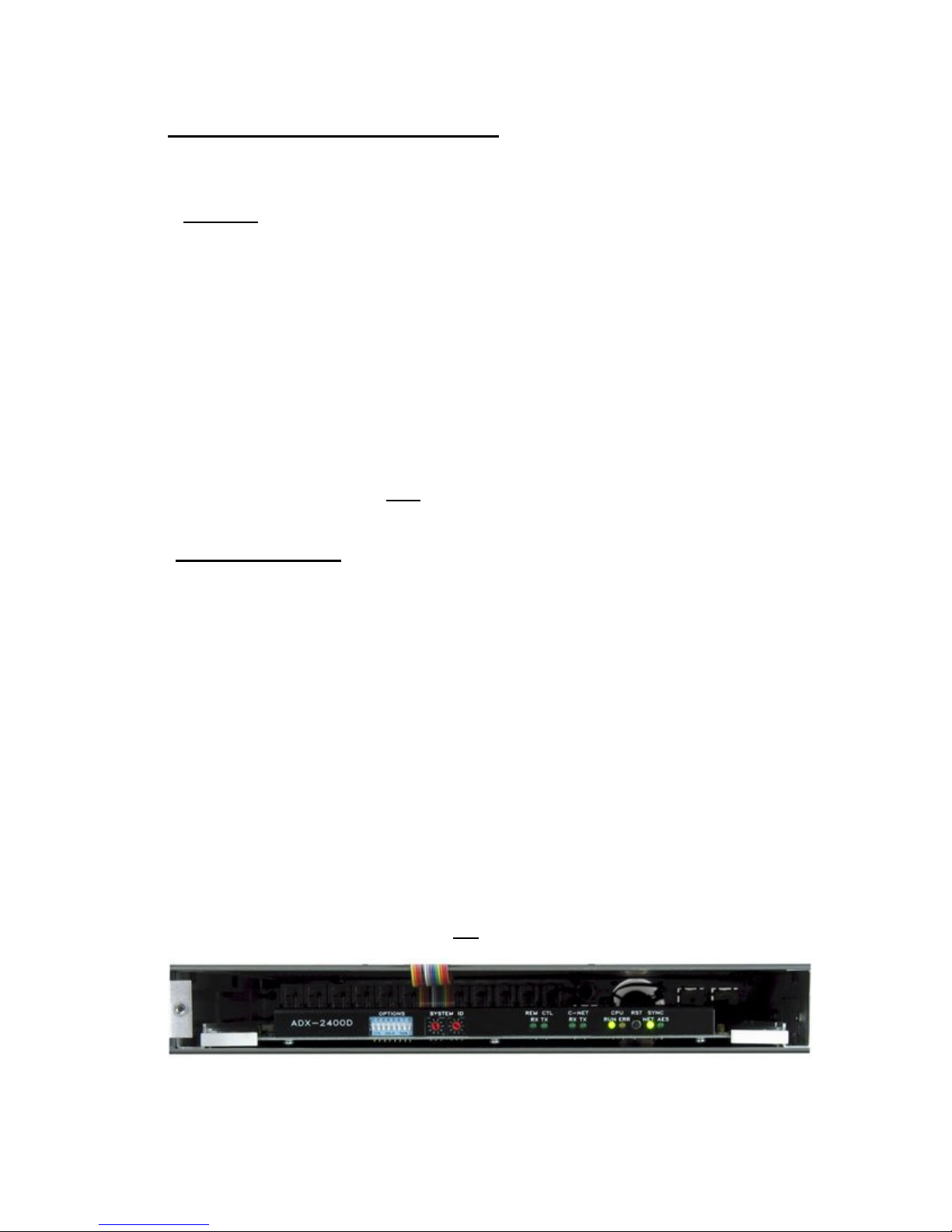
To select NORMAL mode, turn section 3 of the options dipswitch on the subpanel (behind the front panel) OFF
The ANNOUNCE BOOTH mode is selected when the ADX-2400 is used to provide the
'head end' or truck end of an ethernet-based announce booth system, using either ADX120 Announce Units, or ADX-140 XLR Interface Frames (or both) to provide a fully selfcontained announce booth system using copper or fiber ethernet as the transmission
medium.
and press the Reset button.
In this mode, the ADX-2400 can support up to four ADX-120s or ADX-140s, in any
combination. The ADX-2400 transmits and receives four bundles of six channels each.
The transmission utilizes the Cobranet 'low-latency' mode, and results in a path latency
of 2.5 milliseconds.
The DSPs are reconfigured to provide routing matrices for IFB source selection, PGM
source selection, Talkback output configuration, and 4-wire port assignments for the PL
channels.
Bundle numbers are set automatically depending on the assigned system ID numbers
for the remote devices (ADX-120, ADX-140).
To select ANNOUNCE BOOTH mode, turn section 3 of the options dipswitch on
the sub-panel (behind the front panel) ON
and press the Reset button.
Options Dipsw ^ ^ System ID Switch ^ Reset Button
4

LOW-LATENCY OPERATION IN NORMAL MODE
It is possible to operate the ADX-2400M in normal mode, but with low-latency
transmission. Low-latency transmission reduces the path delay from one ADX-2400M to
another ADX-2400M from approximately 7 milliseconds (standard mode) to
approximately 2.5 milliseconds (low-latency mode).
This mode is useful if using ADX-2400's for IFB returns or some other delay-critical
application.
Note that the ADX-2400s on both ends must operate in the same mode (either lowlatency or standard) for audio transmission to occur.
Low-latency operation requires that the ADX-2400M be equipped with a revision J or
later Cobranet interface module. If an earlier version module is installed, and fault
message will be displayed, and low-latency operation is not possible.
Also, note that low-latency operation puts more demands on the network performance.
Ethernet switches which operate comfortably with standard-latency operation my not be
satisfactory with low-latency operation. Gigabit ethernet switches are recommended to
insure satisfactory operation.
To configure the ADX-2400M for low-latency operation, turn on Options
Dipswitch #4, and press Reset.
'LL' indicator will be present in the upper right corner of the display, indicating low-
An
latency operation is selected.
Note that low-latency operation is automatically selected when in Announce Booth
mode, and switch 4 will have no effect.
5

QUICK OPERATION GUIDE - NORMAL MODE
To Select Output Channel (or Channels) to Adjust
Press ‘OUTPUT SELECT’ button, and turn knob until desired channel is selected.
Repeated presses of the 'OUTPUT SELECT' button will advance the selection to the
first channel of the next group of eight individual channels, or to the next group
selection. The order of the channel selection is as follows:
Madi Output 1 through 24 (Individual Outputs)
Madi Outputs 1-8 (Group)
Madi Outputs 9-16 (Group)
Madi Outputs 17-24 (Group)
All Madi Outputs (Group)
Net (Transmitted to Ethernet) Output 1 through 24 (Individual Outputs)
Net Outputs 1-8 (Group)
Net Outputs 9-16 (Group)
Net Outputs 17-24 (Group)
All Net Outputs (Group)
If the high madi channel range is selected in the menu, the madi channels will
be 33-56 instead of 1-24, and the display will change accordingly.
Note that if a group of outputs is selected, any setup adjustments (source, level,
delay) will be applied to all output channels within that group.
To Select Source (for current output or group of outputs)
Press 'SOURCE' button. It will light, and the currently-selected source for the
selected output will be displayed. The sources available for each output are as
follows, and can be selected by turning the knob.
SILENCE The output will be muted
MADI INPUT The output will be fed by the corresponding Madi input
NET INPUT The output will be fed by the corresponding network receiver
888HZ TONE The output will be fed by the internal 888 Hz tone generator
560 HZ TONE The output will be fed by the internal 560 Hz tone generator
You may enable a ‘stereo summing’ mode by selecting any of the following choices,
which follow the above sources in the menu list. In these modes, the selected
source will be combined with the selected source for the other channel in the
even/odd pair; e.g., channels 1 and 2, channels 3 and 4, etc. When a ‘something +
mix’ source is selected, the mixed signal is reduced by 6 dB.
SILENCE + MIX The output will be silence and the other channel mixed
MADI INPUT + MIX The Madi input mixed with the other channel of the pair
NET INPUT + MIX The network receiver mixed with the other channel of the pair
888HZ TONE + MIX 888Hz tone mixed with the other channel of the pair
560 HZ TONE +MIX 560Hz tone mixed with the other channel of the pair
6

To Adjust Level (for current output or group of outputs)
The output level can be adjusted in 0.25 dB increments. Maximum gain is +12 dB.
To adjust, press the 'LEVEL' button, and turn the knob.
To Adjust Delay (for current output or group of outputs)
The delay of each output can be independently adjusted from zero delay through
680 milliseconds, which corresponds to more than 20 frames at 30 frames/sec. The
delay is adjusted by first pressing the 'DELAY' button, then turning the knob to
adjust. Note that the displayed units (milliseconds or frames) is selected in the
menu.
To Adjust Headphone Volume
Press the 'HP VOLUME' button, and turn the knob. The bar graph display will show
the knob 'position'.
To Configure Menu Items
The system has several configuration items which may be set by using the menu
function. Press the 'MENU SELECT' button to enable the menu function. Turn the
knob to select the desired menu item, then press the 'MENU SET' button. Turning
the knob will now change the parameter for this item. When the desired selection is
made, you can exit the MENU SET mode by pressing any other button. (See
section on menu items below).
MENU ITEMS - NORMAL MODE
Item 01 – RX 1-8 Bundle (000-999)
Packet assignment for network receiver 1, which corresponds to audio channels (net
inputs) 1-8. This number should be set to match the bundle number of the
transmitter in another unit which is sending audio to this receiver. Note that bundle
000 is inactive (off). Bundles 001-255 are broadcast bundles, and should only be
used if one transmitter is sending to more than one receiver. Bundles 256-999 are
unicast bundles, and should be used for normal point-to-point, one transmitter/one
receiver operation.
Item 02 – RX 9-16 Bundle (000-999)
Packet assignment for network receiver 2, which corresponds to audio channels (net
inputs) 9-16.
Item 03 – RX 17-24 Bundle (000-999)
Packet assignment for network receiver 3, which corresponds to audio channels (net
inputs) 17-24.
7

Item 04 – TX 1-8 Bundle (000-999)
Packet assignment for network transmitter 1, which corresponds to audio outputs
NET 01 – NET 08.
Item 05 – TX 9-16 Bundle (000-999)
Packet assignment for network transmitter 2, which corresponds to audio outputs
NET 09-NET 16.
Item 06 – TX 17-24 Bundle (000-999)
Packet assignment for network transmitter 3, which corresponds to audio outputs
NET 17 – NET 24.
Item 07 – Conductor Priority (Low – Normal – High)
This item determines the priority of this unit to operate as the 'sync generator' for the
Ethernet audio network. It should normally be set to 'Normal' unless you specifically
want this unit to be the conductor, in which case it could be set to high. If set to
high, this unit will be the conductor unless another is also set high. In the case
where more than one unit has equal priority, the first unit active will assume the
conductor role. This selection isn't too important, since the network will quickly renegotiate a new conductor if the current conductor were to fail or be turned off.
Item 08 – Delay Units (Milliseconds – Frames (30) – Frames (25))
This item selects the units used to display the delay values. It only affects the
display, and if set to Frames, saves the user having to do the arithmetic in his head.
It assumes 33 milliseconds for 30 Frames/sec, and 40 milliseconds for 25
Frames/sec.
Item 09 - Madi Channel Range (1-24, 33-56)
This item selects the madi channels which will be seen as inputs to the ADX-2400M,
and the madi channels which will be output by the ADX-2400M. All other madi
channels in the input stream will be passed through the unit to the output stream
unaltered. Two ADX-2400Ms may be connected in series to use 48 madi channels.
Item 10 - Madi Input (Coax, Optical)
Selects which physical madi input will be enabled. Both optical and coax outputs are
always active regardless of this menu setting.
8

Item 11 - GPI Mode = (Off, Master)
For future or special application use. Should be set to 'Off' normally.
Item 12 - GPI 1/3 Device ID = (00-99)
Item 13 - GPI 2/4 Device ID = (00-99)
For future or special application use. Should be set to 'Off' normally.
Item 14 - Save To User Config 1
Item 15 - Save To User Config 2
Item 16 - Save To User Config 3
There are three user setup files, and these three menu items allow the current
configuration to be saved to these user config files. To save configuration settings,
select the appropriate item number and press 'MENU SET'. The configuration will
be saved to the selected file.
Note that 20 seconds after any configuration change, the current settings are
automatically saved to a default configuration, which will be automatically loaded at
power-up. This is separate from the User Configuration files above.
Item 17 - Recall User Config 1
Item 18 - Recall User Config 2
Item 19 - Recall User Config 3
Selecting one of these three items and pressing 'MENU SET' will cause the settings
previously saved in the selected User Config file to be recalled.
Item 20 - Recall Standard Config
Pressing the 'MENU SET' button will recall a 'standard configuration'. All levels will
be set to unity, all delays will be set to zero, all local outputs will have their sources
set to NET, and all network outputs will have their sources set to MADI. All bundle
numbers will be set to 000.
The following items are STATUS items, and are only to display status
information. They may not be directly changed by the user.
Status Item 01 – NET RX 1 Status (Active or Idle)
Displays ACTIVE status if data is being received by network receiver 1. This
receiver corresponds to net inputs 1-8. Note that the data could be silence; an
active receiver doesn’t necessarily mean that there is audio present.
9
 Loading...