

Lancaster PACESETTER 7-PEL-75B, PACESETTER 7-PEL-150B, PACESETTER 7-PEL-100B, 7-LECR-75, 7-LECR-100 Installation, Operating And Service Manual
...Page 1

INSTALLATION, OPERATING
AND SERVICE MANUAL
PACESETTER
ELECTRONIC WATER SOFTENER
WITH THE PEL VALVE
7-PEL-75B
7-PEL-100B
7-PEL-150B
Congratulations on purchasing your new Lancaster Water Softener. This unit is designed to give
you many years of trouble free service. When installed in accordance with the following instructions
and if given reasonable care, clear-soft water will be the result. For servicing and future inspection
purposes, please le this booklet with your important documents.
PAGE 1
Page 2

OPERATING PARAMETERS
Minimum / Maximum Operating Pressures 20 psi (138 kPa) - 125 psi (862 kPa)
Minimum / Maximum Operating Temperatures 40°F (4°C) - 110°F (43°C)
Supply Voltage/ Frequency 120V AC/ 60 Hz Other Options Available
Power Consumption 9.5 W
Output Voltage 12V AC
Output Current 500 mA
GENERAL WARNINGS
The control valve, ttings and/or bypass are designed to accommodate minor plumbing misalignments but are not designed
to support the weight of a system or the plumbing.
Do not use Vaseline, oils, other hydrocarbon lubrications or spray silicone anywhere. A silicone lubricant may be used on
black o-rings but is not necessary. Avoid any type of lubricants, including silicone, on red or clear lip seals.
The nuts and caps are designed to be unscrewed or tightened by hand or with the special plastic wrench (P/N V3193). If
necessary, pliers can be used to unscrew the nut or cap. Do not use a pipe wrench to tighten or loosen nuts or caps. Do not
place screwdriver in slots on caps and/or tap with hammer.
Do not use pipe dope or any other sealant on threads. Teon tape must be used on the threads of the 1” NPT elbow or the
1/4” NPT connection and on the threads for the drain line connection. Teon tape is not necessary on the nut connection or
caps because of o-ring seals.
After completing any valve maintenance involving the drive assembly and pistons, press and hold NEXT and REGEN
button for three seconds or unplug power source jack from printed circuit board (black wire) and plug back in. This resets
the electronics and establishes the service piston position. The display should ash all wording , then ash software version
(e.g. 220.1) and then reset the valve to the service position.
All plumbing should be done in accordance with local plumbing codes. The pipe size of the drain line should be a minimum
of 1/2”. Backwash ow rates in excess of 7 gpm or length in excess of 20’ require 3/4” drain line.
Solder joints near the drain must be done prior to connecting the drain line ow control tting. Leave at least 6” between the
drain line control tting and solder joints when soldering pipes that are connected on the drain line control tting. Failure to
do this could cause interior damage to the drain line ow control tting.
When assembling the installation tting package(P/N V3007) to the inlet and outlet (see Page 7), connect the tting to the
plumbing system rst and then attach the nut, split ring and o-ring. Heat from soldering or solvent cements may damage the
nut, split ring or o-ring. Solder joints should be cool and solvent cements should be set before installing the nut, split ring and
o-ring. Avoid getting primer and solvent cement on any part of the o-rings, split rings, bypass valve or control valve.
Plug into an electrical outlet. NOTE: All electrical connections must be connected according to local codes. (Be certain the
outlet is uninterrupted.) Install grounding strap on metal pipes.
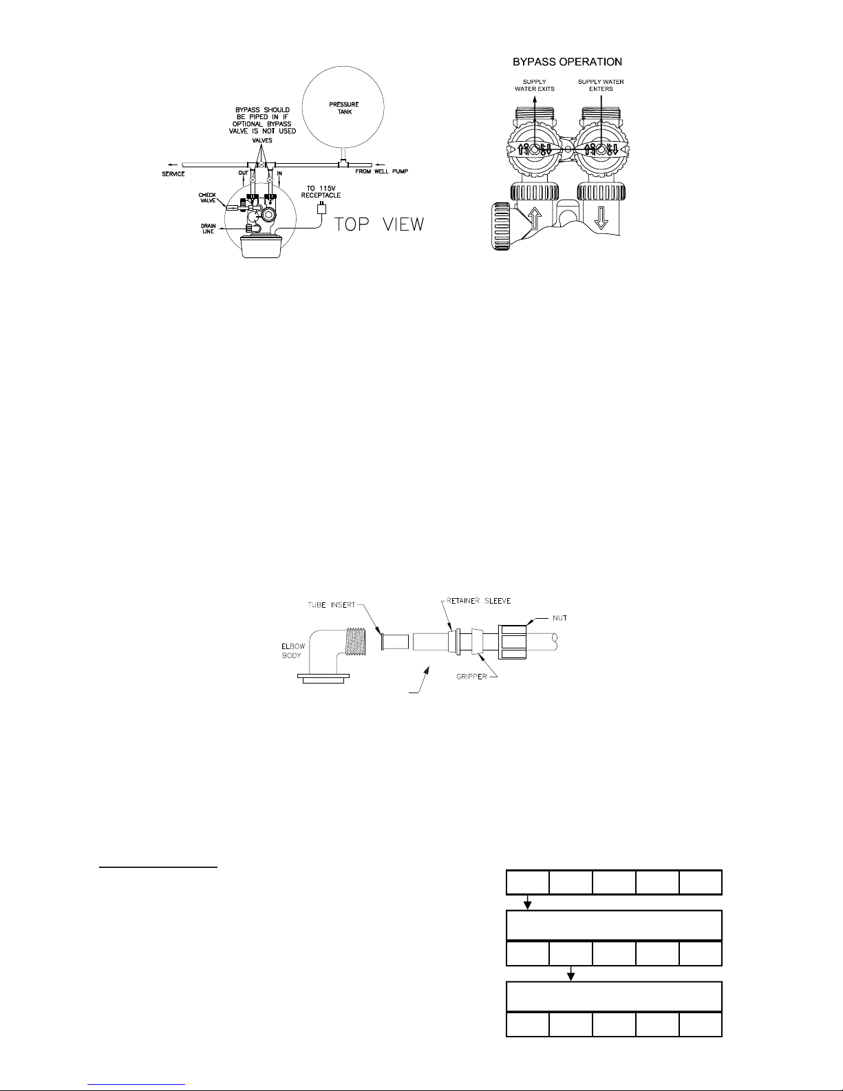
Place softener in desired location close to water supply inlet, after pressure tank, and near a source for waste water, (utility
sink, oor drain or sewer line). A 115/120V, 60 Hz uninterrupted outlet is required. Keep softener far enough away from walls
and other obstructions to allow enough room for servicing the unit. All sillcocks and similar xtures that will use untreated
water must have their pipes connected to the hard water side of the softener. A bypass valve (optional accessory) should
be installed so that water will be available if it should be necessary to shut off the pressure in order to service the softener.
The cabinet tank or mineral tank must be reasonably level and solidly in place. Prior to beginning work to the system, make
sure that water pressure is shut off at the incoming water supply and that several water spigots are open to provide sufcient
venting for drainage of that system.
Arrows are molded into the control valve to show the direction of the ow.
OPTIONAL BYPASS VALVE: The bypass valve easily connects to the control valve body using nuts that only require hand
tightening. Install with red knobs in the upward position. Press end of bypass valve with o-rings into valve. Hand tighten nuts.
Place into BYPASS OPERATION (gure 1 page 3).
Avoid getting primer and solvent cement on any part of the o-rings or split rings, bypass valve or control valve. DO NOT use
pipe dope or any other sealant on threads. Teon tape is not necessary on the caps because of o-ring seals. Do not use
Vaseline or other unacceptable lubricants on o-rings. A silicone lubricant may be used on black o-rings.
DRAIN LINE: The 3/4” drain line elbow accommodates 5/8” poly tube or 3/4” NPT drain line connections. The nut and poly
tube insert for the 3/4” drain line elbow is designed for use with exible poly tube only. The drain line elbow can be rotated
so the outlet can be oriented toward the nearest drain.
INSTALLATION
PAGE 2
Page 3
Click to buy NOW!
P
D
F
-
X
C
H
A
N
G
E
w
w
w
.
d
o
c
u
-
t
r
a
c
k
.
c
o
m
FIGURE 1
FIGURE 1
TO INSTALL 5/8” POLY TUBE DRAIN LINE: The poly tube insert is shipped attached to the drain line elbow’s locking clip.
Press the insert into the drain line (5/8” poly tube not included). Loosen nut of the drain line elbow. Press 5/8” poly tube with
insert into the drain line elbow until it seats on the back of the tting. Tighten nut.
It is simplest to run the drain line into a sump pump pit or washing machine drain if possible. If this is not practical, a tting
with a trap must be installed in a sewer line. Place the trap as close to the vent as possible to prevent siphoning of the trap
when large amounts of waste water go through the sewer line. DO NOT pipe the drain line solidly into the waste line, as this
is prohibited by most plumbing codes. The drain line should enter the trap from above so the water will not back up in the
drain line if sewer should become plugged up and the trap overow. The trap should have a short pipe extending from it to
prevent splashing when water runs into the trap from drain line.
BRINE LINE CONNECTIONS: 3/8” poly tube is shipped within the instruction/warranty card packet afxed to the control
valve. One poly tube insert is shipped on the brine line elbow’s locking clip, the second is taped to the cap of the brine well.
Remove the locking clip by pulling straight out. Remove the white poly tube insert from the locking clip, and replace the
locking clip on the brine line elbow of the control valve.
Press the poly tube insert into the provided 3/8” poly tube. Press the poly tube and insert into the nut until it is fully seated
into the tting. Do not use pipe dope or any other sealant on threads. Teon tape is not needed on the threads. Tighten nut
securely to create a pressure tight connection. Pliers or crescent wrench may be used. The nut, gripper and retainer sleeve
is a three piece assembly that can come apart if removed from the elbow body. Parts must be reassembled exactly as
shown to function properly. If the nut is completely removed from the body, slip the nut, plastic gripper and retainer sleeve
on to the tube then tighten on to the tting.
Install the second poly tube insert into the end of the 3/8” poly tube and repeat instructions above to install into the brine
tank’s brine line tting.
BRINE TANK OVERFLOW PRECAUTION: Attach a 1/2” poly tube (not provided) to the barbed tting on the outside of the
tank. This poly tube should be piped to drain to allow brine to discharge to drain in the event of an overow condition.
PROGRAMMING THE CONTROL VALVE: Note: A quick-reference card is stored inside the front cover of the control valve.
To access this card, slightly pull tabs on side of cover outward and pull cover forward. Plug the electrical cord into a 115
Volt receptacle. DO NOT plug into an outlet controlled by a wall switch or pull chain that could inadvertently be turned off.
Wait a couple of seconds for control valve to “home” itself. Panel should display “TIME” and the time of day will be ashing.
SET TIME OF DAY
STEP 1: Press SET CLOCK.
STEP 2: Set current hour of the day by pressing ▲
or ▼ buttons. AM/ PM toggles after 12.
STEP 3: Press NEXT. Set current minutes by
pressing ▲ or ▼ buttons.
STEP 4: Press NEXT to exit SET CLOCK.
3/8”
POLY TUBE
PAGE 3
SET
CLOCK
SET TIME
NEXT
▲ ▼
STEP 1
REGEN
STEP 2
6:35
SET
CLOCK
SET TIME
NEXT
▲ ▼
REGEN
STEP 3
6:35
SET
CLOCK
NEXT
▲ ▼
REGEN
PM
PM
Page 4

ADDITIONAL PROGRAMMING INFORMATION AVAILABLE FROM
STEP 1: Press NEXT and ▲ simultaneously for 3 seconds.
STEP 2: Hardness: Set the amount of hardness in grains of hardness as
calcium carbonate per gallon using the ▲ or ▼ buttons. The default
is 20. The available range is 1 to 150 in 1 grain increments.
STEP 3: Press NEXT. Regen day: This sets the maximum number of days
between regenerations. This days override feature can be shut off
by pressing the ▼ button until “OFF” appears. Set the maximum
number of days between by pressing ▲ or ▼. Range is 1– 28 days.
If the OFF position is selected, the softener will regenerate based
soley on the gallons capacity.
STEP 4: Press NEXT. Regeneration time (hour): Set the hour of the day for
regeneration to occur by using ▲ or ▼ buttons. AM/ PM toggles
after 12. The default time is 2:00 am.
STEP 5: Press NEXT. Regeneration time (minutes): Set the minutes of the
day for regeneration by using ▲ or ▼ buttons. Press NEXT to exit
Displays/Settings. Current time of day will be dislpayed.
SET HARDNESS, DAYS OVERRIDE & REGENERATION TIME
LANCASTER WATER TREATMENT UPON REQUEST.
SET
CLOCK
SET
NEXT
HARDNESS
▲ ▼
STEP 1
REGEN
STEP 2
20
SET
REGEN
DAY
SET
SET
SET
NEXT
NEXT
NEXT
NEXT
CLOCK
SET
14
CLOCK
SET TIME
REGEN
2:00
CLOCK
SET TIME
2:00
REGEN
CLOCK
▲ ▼
▲ ▼
▲ ▼
▲ ▼
REGEN
STEP 3
REGEN
STEP 4
REGEN
STEP 5
REGEN
AM
AM
SET HARDNESS, DAYS OVERRIDE & REGENERATION TIME
STEP 1: Press NEXT and ▲ simultaneously for 3 seconds.
STEP 2: Hardness: Set the amount of hardness in grains of hardness
as calcium carbonate per gallon using the ▲ or ▼ buttons. The
default is 20. The available range is 1 to 150 in 1 grain increments.
STEP 3: Press NEXT. Regen day: This sets the maximum number of days
between regenerations. This days override feature can be shut off
by pressing the ▼ button until “OFF” appears. Set the maximum
number of days between by pressing ▲ or ▼. Range is 1– 28
days. If the OFF position is selected, the softener will regenerate
based solely on the gallons capacity.
STEP 4: Press NEXT. Regeneration time (hour): Set the hour of the day for
regeneration to occur by using ▲ or ▼ buttons. AM/ PM toggles
after 12. The default time is 2:00 am.
STEP 5: Press NEXT. Regeneration time (minutes): Set the minutes of the
day for regeneration by using ▲ or ▼ buttons. Press NEXT to exit
Displays/Settings. Current time of day will be displayed.
PLACING UNIT INTO SERVICE: Make sure inlet and outlet valves are to their closed positions. If using optional
bypass, place in bypass position. Turn on main water supply. Open a cold water faucet. This will clear the lines of any debris
(solder, pipe dope, etc.) that may be in the line. Let water run at tap for a couple of minutes, or until clear. Turn off faucet.
Manually add 1½ gallons of water to the brine tank.
• Press and hold the REGEN button for approximately 5 seconds until the motor starts.
• Wait until display reads BACKWASH and numbers start counting down.
• Momentarily press REGEN again. Wait until display reads BRINE and numbers start counting down.
• Momentarily press REGEN again. Valve is now in the second BACKWASH position.
If using optional bypass SLOWLY turn bypass valve to DIAGNOSTIC position (gure 2) or slowly open inlet valve to allow
water to slowly enter the softener.
When water is owing steadily to drain without the presence of air, momentarily press REGEN again. Display will read
RINSE.
Open the outlet valve of the softener, or if using optional bypass place to NORMAL OPERATION MODE (gure 3).
Allow control to nish the RINSE cycle. It will then advance to the FILL position. The brine tank will now automatically ll with
the proper volume of water for the rst regeneration.
Allow the control to automatically advance to the SOFTENING position.
Load the brine tank with salt. Solar Salt is recommended.
SANITIZING: Use 2 oz. of 5¼% household chlorine bleach for each cubic foot of resin. Pour bleach directly into the brine
well of the softener. Press and hold the REGEN button for 5 – 6 seconds until the motor starts running. Allow system to
complete the regeneration automatically. Check for other local and state codes which may also specify sanitation methods.
FIGURE 2
FIGURE 3
PAGE 4
Page 5

Item No. Quantity Part No. Description
WS1TC & WS1.25 TC Manual Page 13
6
2
4b
4a
5
1
3
7
8
WS1TC Drive Cap Assembly, Down ow Piston, Regenerant Piston and Spacer Stack Assembly
Drawing No. Order No. Description Quantity
1 V3005 WS1 Spacer Stack Assembly 1
2 V3004 Drive Cap ASY 1
3 V3178 WS1 Drive Back Plate 1
4 V3011 WS1 Piston Down ow ASY 1
5 V3174 WS1 Regenerant Piston 1
6 V3135 O-ring 228 1
7 V3180 O-ring 337 1
8 V3105 O-ring 215 (Distributer Tube) 1
Not Shown
V3001 WS1 Body ASY Down ow
1
V3001-02 WS1 Mixing Valve Body ASY
Note: The regenerant piston is not used in backwash only applications.
Black Plug
4
Injector Cap, Injector Screen, Injector, Plug and O-Ring
V3010-1A WS1 INJECTOR ASY A BLACK
1
V3010-1B WS1 INJECTOR ASY B BROWN
V3010-1C WS1 INJECTOR ASY C VIOLET
V3010-1D WS1 INJECTOR ASY D RED
V3010-1E WS1 INJECTOR ASY E WHITE
V3010-1F WS1 INJECTOR ASY F BLUE
V3010-1G WS1 INJECTOR ASY G YELLOW
V3010-1H WS1 INJECTOR ASY H GREEN
V3010-1I WS1 INJECTOR ASY I ORANGE
V3010-1J WS1 INJECTOR ASY J LIGHT BLUE
V3010-1K WS1 INJECTOR ASY K LIGHT
GREEN
Front Cover and Drive Assembly
V3002 WS1 Drive ASY *
V3186 WS1 AC ADAPTER 120V-12V
1
V3186EU WS1 AC ADAPTER 220-240V-12V EU
V3186UK WS1 AC ADAPTER 220-240V-12V UK
V3186-01 WS1 AC ADAPTER CORD ONLY
Battery Fully Seated
When replacing the battery, align
positives and push down to fully seat.
Correct
Battery
Orienta-
tion
Battery replacement is
3 volt lithium coin cell
type 2032.
AC Adapter U.S. International
Supply Voltage 120 V AC 230V AC
Supply Frequency 60 Hz 50 Hz
Output Voltage 12 V AC 12 V AC
Output Current 500 mA 500 mA
1
Battery replacement is
3 volt lithium coin cell
type 2032.
1
Battery replacement is
3 volt lithium coin cell
type 2032.
1 1 V3175CC Front Cover Assembly
2 1 V3107 Motor
3 1 V3106 Drive Bracket & Spring Clip
4 1 V3108CC PC Board
5 3 V3110 Drive Gear 12 x 36
6 1 V3109 Drive Gear Cover
2 thru 6 V3002CC Drive Assembly - (parts 2-6)
Not
Shown
1 V3186 Transformer 110V-12V
DRIVE CAP ASSEMBLY, DOWNFLOW PISTON, REGENERANT PISTON AND SPACER STACK ASSEMBLY
Item No. Quantity Part No. Description
1 1 V3005 Spacer Stack Assembly
2 1 V3004 Drive Cap Assembly
3 1 V3135 O-Ring 228
4 1 V3011 Piston Assembly
5 1 V3174 Regenerant Piston
6 1 V3180 O-Ring 337
1
3
Item No. Quantity Part No. Description
1 1 V3176 Injector Cap
2 1 V3152 O-Ring 135
3 1 V3177 Injector Screen
4 1 V3010-1Z Injector Assy Z Plug
5 1 V3010-1C Injector Assy C Violet
5 1 V3010-1E Injector Assy E White
5 1 V3010-1F Injector Assy F Blue
4
5 1 V3010-1G Injector Assy G Yellow
Not
Shown
3
5
2
Not
Shown
* Injector plug and injector each contain one 011 and one 013
O-Ring
PAGE 5
INJECTOR, INJECTOR CAP, SCREEN AND O-RING
* V3170 O-Ring 011
* V3171 O-Ring 013
FRONT COVER AND DRIVE ASSEMBLY
6
Page 6

DRAIN LINE - 3/4”
WS1 & WS1.25 Drawings & Service Manual Page 17
Water Meter, Meter Plug and Mixing Valve
Drawing No. Order No. Description Quantity
1 V3151 WS1 Nut 1” QC 1
2 V3003* WS1 Meter ASY 1
3 V3118-01 WS1 Turbine ASY 1
4 V3105 0-ring 215 1
5 V3003-01 WS1 Meter Plug ASY 1
6 V3013 Mixing Valve Optional
*Order number V3003 includes V3118-01 WS1 Turbine ASY and V3105 O-ring
215.
3
4
5
1
2
6
WS1 & WS1.25 Drawings & Service Manual Page 15
Drain Line – 3/4”
Drawing No. Order No. Description Quantity
1 H4615 Elbow Locking Clip 1
2 PKP10TS8-BULK Polytube insert 5/8 Option
3 V3192 WS1 Nut ¾ Drain Elbow Option
4* V3158-01 WS1 Drain Elbow ¾ Male 1
5 V3163 O-ring 019 1
6* V3159-01 WS1 DLFC Retainer ASY 1
7
V3162-007 WS1 DLFC 0.7 gpm for ¾
One DLFC
must be
used if ¾
tting is
used
V3162-010 WS1 DLFC 1.0 gpm for ¾
V3162-013 WS1 DLFC 1.3 gpm for ¾
V3162-017 WS1 DLFC 1.7 gpm for ¾
V3162-022 WS1 DLFC 2.2 gpm for ¾
V3162-027 WS1 DLFC 2.7 gpm for ¾
V3162-032 WS1 DLFC 3.2 gpm for ¾
V3162-042 WS1 DLFC 4.2 gpm for ¾
V3162-053 WS1 DLFC 5.3 gpm for ¾
V3162-065 WS1 DLFC 6.5 gpm for ¾
V3162-075 WS1 DLFC 7.5 gpm for ¾
V3162-090 WS1 DLFC 9.0 gpm for ¾
V3162-100 WS1 DLFC 10.0 gpm for ¾
Valves are shipped without drain line ow control (DLFC) - install DLFC before using. Valves
are shipped without ¾ nut for drain elbow (polytube installation only) and 5/8" polytube insert
(polytube installation only).
*4 and 6 can be ordered as a complete assembly - V3331 WS1 Drain Elbow and Retainer Asy
Page 14 WS1 & WS1.25 Drawings & Service Manual
Re ll Flow Control Assembly and Re ll Port Plug
Water
Flow
Proper RFC orientation
directs re ll water ow
towards the washer face
with rounded edge and text.
Drawing No. Order No. Description Quantity
1 V3195-01 WS1 Re ll Port Plug Asy
This part is required for backwash only sys-
tems
2 H4615 Elbow Locking Clip 1
3 JCP-P-6 Polytube insert 3/8” 1
4 JCPG-6PBLK Nut 3/8” 1
5 H4613 Elbow Cap 3/8” 1
6 V3163 0-ring 019 1
7 V3165-01* WS1 RFC Retainer Asy 1
8 V3182 WS1 RFC 1
9 V3330-01 WS1 Brine Elbow Asy w/RFC 3/8" 1
Not Shown V3552 WS1 Brine Elbow Asy w/RFC 1/2" Option
Not Shown H4650 Elbow ½” with nut and insert Option
*Assembly includes V3182 WS1 RFC.
9
Item No. Quantity Part No. Description
1 1 H4615 Elbow Locking Clip
2 1 V3194 Polytube Insert 5/8
3 1 V3192 Nut for 3/4 Drain Elbow
4 1 V3158 3/4 Drain Elbow
5 1 V3163 O-Ring 019
6 1 V3159 DLFC Retainer
7 1 V3162-017 DLFC 1.7
7 1 V3162-027 DLFC 2.7
2
7
3
4
6
1
5
Item No. Quantity Part No. Description
1 1 H4615 Elbow Locking Clip
2 1 H4614 Polytube Insert 3/8”
3 1 H4612 Nut 3/8”
4 1 H4613 Elbow Cap 3/8”
5 1 V3163 O-Ring 019
6 1 V3165 RFC Retainer Assy
7 1 V3182 RFC
WATER METER AND METER PLUG
Item No. Quantity Part No. Description
1 1 V3151 Nut 1” QC
2 1 V3003* Meter Assy
3 1 V3118-01 Turbine Assy
4 1 V3105 O-Ring 215
5 1 V3003-01 Meter Plug Assy
*Part No. V3003 includes Items 2, 3 and 4
Water
Proper DLFC orientation
directs water ow towards
the washer face with
rounded edge.
Flow
4
BRINE REFILL
*Part No. V3165 Includes Items 6 and 7
PAGE 6
Page 7

Click to buy NOW!
P
D
F
-
X
C
H
A
N
G
E
w
w
w
.
d
o
c
u
-
t
r
a
c
k
.
c
o
m
PARTS
Item No. Quantity Part No. Description
V3007 1” PVC Male NPT
Elbow Assembly
Standard
1 2 V3151 Nut 1” Quick Connect
2 2 V3150 Split Ring
3 2 V3105 O-Ring 215
4 2 V3149 1” PVC Male NPT Elbow
V3191-01 Vertical
Adapter Assembly
Optional
BP2000 Bypass Valve
Item No. Quantity Part No. Description
1 2 V3151 Nut 1” Quick Connect
2 2 V3150 Split Ring
3 2 V3105 O-Ring 215
4 2 V3145 Bypass 1” Rotor
5 2 V3146 Bypass Cap
6 2 V3147 Bypass Handle
7 2 V3148 Bypass Rotor Seal Retainer
8 2 V3152 O-Ring 135
9 2 V3155 O-Ring 112
10 2 V3156 O-Ring 214
ADDITIONAL OPTIONAL FITTINGS
Part Number Description
V3007-01 3/4” X 1” PVC Solvent Elbow Assembly
V3007-02 1” Brass Sweat Assembly
V3007-03 3/4” Brass Sweat Assembly
V3007-12 3/4” Shark Bite Assembly
V3007-13 1” Shark Bite Assembly
V3007-15 3/4” John Guest QC Elbow Assembly
V3007-17 1” John Guest Straight QC
Item No. Quantity Part No. Description
1 2 V3151 Nut 1” Quick Connect
2 2 V3150 Split Ring
3 2 V3105 O-Ring 215
4 2 V3191 Vertical Adapter
1
2
3
4
4740 Brine Valve Assembly
Item No. Quantity Part No. Description
1 1 H4600 3/8” Safety Brine Valve
2 2 10151 Pin
3 1 H4640-32 Float Assembly
4 1 H4500-30.50 Air Check Assembly
PAGE 7
Page 8

PROBLEM POSSIBLE CAUSE SOLUTION
1. Timer does not display time of day.
TROUBLESHOOTING PROCEDURES
a. Transformer unplugged a. Connect power
b. No electric power at outlet b. Repair outlet or use working outlet
c. Defective transformer c. Replace transformer
d. Defective PC board d. Replace PC board
a. Switched outlet a. Use uninterrupted outlet
2. Timer does not display correct time of day.
3. No Softening/ltering display when water is
owing.
4. Control valve regenerates at wrong time of
day.
5. ERROR followed by Code number:
Error Code 1001– Unable to recognize start
of regeneration.
Error Code 1002– Unexpected stall.
Error Code 1003 – Motor ran to long, timed
out trying to reach next cycle position.
Error Code 1004 – Motor ran to long, timed
out trying to reach home position.
If other Error Codes display contact the
factory.
6. Control valve stalled in regeneration.
7. Control valve does not regenerate
automatically when REGEN button is
depressed and held.
8. Control valve does not regenerate
automatically but does when REGEN button
is depressed.
9. Time of day ashes on and off.
b. Power outage b. Reset time of day
c. Defective PC board c. Replace PC board
a. Bypass valve in bypass position. a. Put bypass valve in service position
b. Meter connection disconnected. b. Connect meter to PC board
c. Restricted/stalled meter turbine. c. Remove meter and check for rotation or foreign material
d. Defective meter. d. Replace meter
e. Defective PC board. e. Replace PC board
a. Power outages a. Reset control valve to correct time of day
b. Time of day not set correctly b. Reset to correct time of day
c. Time of regeneration incorrect c. Reset regeneration time
d. Control valve set at “on O” (immediate regeneration) d. Check control valve set-up procedure regeneration time
e. Control valve set at NORMAL + O e. Check control valve set-up procedure regeneration time
a. Control valve has just been serviced a. Press NEXT and REGEN for 3 seconds or unplug power
b. Foreign matter is lodged in control valve b. Check piston and spacer stack assembly for foreign matter.
c. High drive forces on piston c. Replace piston (s) and spacer stack assembly.
d. Control valve piston not in home position d. Press NEXT and REGEN for 3 seconds or unplug power
e. Motor not inserted fully to engage pinion, motor wires broken or
disconnected, motor failure
f. Drive gear label dirty or damaged, missing or broken gear f. Replace or clean drive gear.
g. Drive bracket incorrectly aligned to back plate g. Reset drive bracket properly.
h. PC board is damaged or defective h. Replace PC board.
i. PC board incorrectly aligned to drive bracket i. Ensure PC board is correctly snapped onto drive bracket.
a. Motor not operating a. Replace motor
b. No electric power at outlet b. Repair outlet or use working outlet
c. Defective transformer c. Replace transformer
d. Defective PC board d. Replace PC board
e. Broken drive gear or drive cap assembly e. Replace drive gear or drive cap assembly
f. Broken piston retainer f. Replace drive cap assembly
g. Broken main or regenerant piston g. Replace main or regenerant piston
a. Transformer unplugged a. Connect transformer
b. No electric power at outlet b. Repair outlet or use working outlet
c. Broken drive gear or drive cap assembly c. Replace drive gear or drive cap assembly
d. Defective PC board d. Replace PC board
a. Bypass valve in bypass position a. Put control valve in service piston
b. Meter connection disconnected b. Connect meter to PC board
c. Restricted/stalled meter turbine c. Remove meter and check for rotation or foreign matter
d. Defective meter d. Replace meter
e. Defective PC board e. Replace PC board
f. Set-up error f. Check control valve set-up procedure
a. Power has been out more than two hours, the transformer
was unplugged and then plugged back into the wall outlet, the
transformer plug was unplugged and then plugged back into the
board or the NEXT and REGEN buttons were pressed to reset the
valve.
option
option
source jack (black wire) and plug back in to reset control
valve.
source jack (black wire) and plug back in to reset control valve.
e. Check motor and wiring. Replace motor if necessary.
a. Reset the time of day
7/14
1340 MANHEIM PIKE ● LANCASTER PA 17601-3196 ● TEL:717-397-3521 ● FAX: 717-392-0266
www.lancasterwatertreatment.com ● E-mail: info@lancasterpump.com
A DIVISION OF C-B TOOL CO.
PAGE 8
 Loading...