

Lancaster 7-LXIM-3, 7-LXDAN-1.5, 7-LXIM-1, 7-LXIM-2, 7-LXCT-1 Installation, Operating And Service Manual
...Page 1

WATER FILTERS AND NEUTRALIZERS
INSTALLATION, OPERATING AND
SERVICE MANUAL
ELECTRONIC WATER FILTER WITH THE
X-FACTOR CONTROL VALVE
ACID NEUTRALIZERS
7-LXDAN-1
7-LXDAN-1.5
7-LXDAN-2
7-LXDAN-3
IRON FILTER
7-LXIM-1
7-LXIM-2
7-LXIM-3
COLOR, TASTE, ODOR
7-LXCT-1
7-LXCT-2
SEDIMENT/ TURBIDITY
7-LXST-1
7-LXST-2
7-LXST-3
AERATION-SULFUR & IRON
7-LXCTAIR-1
7-LXCTAIR-2
7-LXCTAIR-3
AERATION-IRON ONLY
7-LXIMAIR-1
7-LXIMAIR-2
7-LXCT-3
Congratulations on purchasing your new Lancaster Water Filter. This unit is designed to give you
many years of trouble free service. For servicing and future inspection purposes, please le this
booklet with your important documents.
In the event that you need assistance for servicing your water lter, please rst contact the
professional contractor who installed the system.
7-LXIMAIR-3
PAGE 1
Page 2

TABLE OF CONTENTS
Job Specications ......................................................................................................................... 2
Components ................................................................................................................................. 2
Pre-Installation Review ................................................................................................................. 3
General Installation and Service Warnings .................................................................................. 3
Bypass Valve Operation ............................................................................................................... 4
Installation Instructions, Diagrams ................................................................................................ 5, 6
Installation Instructions for 7-LXCTAIR, 7-LXIMAIR ..................................................................... 7
Placing Filter into Service ............................................................................................................. 8
General Operation ........................................................................................................................ 8
Set Time of Day ............................................................................................................................ 9
Adjust Days Between Backwash or Time of Backwash ................................................................ 9, 10
Low Battery.................................................................................................................................... 10
Contact Screen Programming ...................................................................................................... 10
Parts Diagrams ............................................................................................................................. 11-17
Service Instructions ...................................................................................................................... 18-20
Troubleshooting ............................................................................................................................ 21-23
JOB SPECIFICATIONS
MODEL NO.
INSTALLATION DATE
SERIAL NUMBER
INSTALLER NAME PHONE
ADDRESS
UNTREATED WATER TEST AT TIME OF INSTALLATION
Hardness CaCo3 (gpg)
Iron (ppm or mg/l)
pH
TDS (ppm or mg/l)
COMPONENTS
MODEL
7-LXDAN-1 FG1047DVT, 10x47
7-LXDAN-1.5 FG1054DVT, 10x54
7-LXDAN-2 FG1348DVT, 13x48
7-LXDAN-3 FG1365DVT, 13x65
7-LXIM-1 FG1044VT, 10x44 A8007, BIRM (1)
7-LXIM-2 FG1348VT, 13x48 A8007, BIRM (2)
7-LXIM-3 FG1465VT, 14x65 A8007, BIRM (3)
7-LXCT-1 FG1044VT, 10x44 A8009, CARBON (1)
MINERAL TANK-
PART NO., dia.”x ht.”
(with dome plug)
(with dome plug)
(with dome plug)
(with dome plug)
PART ID, MINERAL
(BAG qty.)
A8021, CALCITE (2)
A8021, CALCITE (3)
A8021, CALCITE (4)
A8021, CALCITE (6)
MODEL MINERAL TANK-
7-LXCT-2 FG1348VT, 13x48 A8009, CARBON (2)
7-LXCT-3 FG1465VT, 14x65 A8009, CARBON (3)
7-LXST-1 FG1044VT, 10x44 A8014, FILTER AG (1)
7-LXST-2 FG1348VT, 13x48 A8014, FILTER AG (2)
7-LXST-3 FG1465VT, 14x65 A8014, FILTER AG (3)
7-LXCTAIR-1 FG1054VT, 10x54 A8056, (1)
7-LXCTAIR-2 FG1465VT, 14x65 A8056, (2)
7-LXCTAIR-3 FG1665VT, 16x65 A8056, (3)
7-LXIMAIR-1 FG1054VT, 10x54 A8007, BIRM (1)
7-LXIMAIR-2 FG1465VT, 14x65 A8007, BIRM (2)
7-LXIMAIR-3 FG1665VT, 16x65 A8007, BIRM (3)
Other:
PART NO., dia.”x ht.”
PART ID, MINERAL
(BAG qty.)
CATALYTIC
CARBON
CATALYTIC
CARBON
CATALYTIC
CARBON
PAGE 2
Page 3

PRE-INSTALLATION
REVIEW
GENERAL INSTALLATION
AND SERVICE WARNINGS
WATER PRESSURE: A minimum of 20 pounds of water
pressure (psi) is required for backwash. Maximum 100
psi. CAUTION: the lter cannot be subject to a vacuum
due to loss of pressure (such as a water main break or
submersible well pump check valve failure).
WATER TEMPERATURE: The range of water temperature
is 35°F to 100°F. DO NOT install any water lter with less
than 10 feet of piping between its outlet and the inlet of a
water heater.
AMBIENT TEMPERATURE: DO NOT locate lter where it
or its connections (including the drain and overow lines)
will ever be subject to room temperatures under 33°F.
ELECTRICITY: An uninterrupted 120 volt 60Hz source is
required. Make sure electrical source is not on a timer
or switch. All electrical connections must be connected
according to local codes. The plug-in transformer is for
dry locations only. Surge protection is recommended with
all electrical connections.
DRAIN: All plumbing should be done in accordance with
local plumbing codes. The distance between the drain
and the water lter should be as short as possible. The
pipe size for the drain line should be a minimum of 1/2”
(inside diameter of pipe). For backwash rates of 7 gpm or
higher, use a 3/4” drain line.
FILTERING: It is recommended that the lter be installed
to treat both the hot and cold water supply. Outside faucets
should be left on untreated water.
BYPASS: A bypass valve (optional accessory) should
be installed so that water will be available if it should be
necessary to shut off the pressure in order to service the
lter.
The control valve, tting and/or bypass are designed to
accommodate minor plumbing misalignments but are
not designed to support the weight of a system or the
plumbing.
Do not use Vaseline, oils, other hydrocarbon lubricants or
spray silicone anywhere. A silicone lubricant may be used
on black o-rings but is not necessary. Avoid any type of
lubricants, including silicone, on the clear lip seals.
The nuts and caps are designed to be unscrewed or
tightened by hand or with the special plastic wrench
(V3193). If necessary, pliers can be used to unscrew the
nut or cap. Do not use a pipe wrench to tighten or loosen
nuts or caps. Do not place a screw driver in the slots on
caps and/or tap with a hammer.
Do not use pipe dope or other sealants on threads. Use
Teon tape on the threaded inlet, outlet and drain ttings.
Teon tape is not necessary on the nut connection or caps
because of o-rings seals.
After completing any valve maintenance involving the
drive assembly or the drive cap assembly and pistons,
unplug power source jack from the printed circuit board
(black wire) and plug back in or press and hold
REGEN
and
and establishes the service piston position. The display
should ash the software version and then reset the valve
to the service position.
Solder joints near the drain must be done prior to
connecting the drain line ow control tting. Leave at least
6” between the drain line control tting and solder joints
when soldering pipes that are connected on the drain
line control tting. Failure to do this could cause interior
damage to the drain line ow control tting.
When assembling the installation tting package (inlet
and outlet), connect the tting to the plumbing system rst
and then attach the nut, split ring and o-ring. Heat from
soldering or solvent cements may damage the nut, split
ring or o-ring. Solder joints should be cool and solvent
cements should be set before installing the nut, split ring
and o-ring. Avoid getting primer and solvent cement on
any part of the o-ring, split rings, bypass valve or control
valve.
Install grounding strap on metal pipes.
This water lter is not to be used for treating water
that is microbiologically unsafe or of unknown
quality without adequate disinfection before or after
treatment.
buttons for 3 seconds. This resets the electronics
NEXT
PAGE 3
Page 4
BYPASS VALVE
The bypass valve is typically used to isolate the control valve from the plumbing system’s water pressure in order to perform control
valve repairs or maintenance. The X-Factor bypass valve is particularly unique in the water treatment industry due to its versatility
and state of the art design features. The 1” full ow bypass valve incorporates four positions, including a diagnostic position that
allows service personal to work on a pressurized system while still providing untreated bypassed water to the facility or residence. Its
completely non-metallic, all-plastic design allows for easy access and serviceability without the need for tools.
The bypass body and rotors are glass lled Noryl® (or equivalent) and the nuts and caps are glass lled polypropylene. All seals are
self-lubricating EPDM to help prevent valve seizing after long periods of non-use. Internal o-rings can easily be replaced if service is
required.
The bypass consists of two interchangeable plug valves that are operated independently by red arrow-shaped handles. The handles
identify the ow direction of the water. The plug valves enable the bypass valve to operate in four positions.
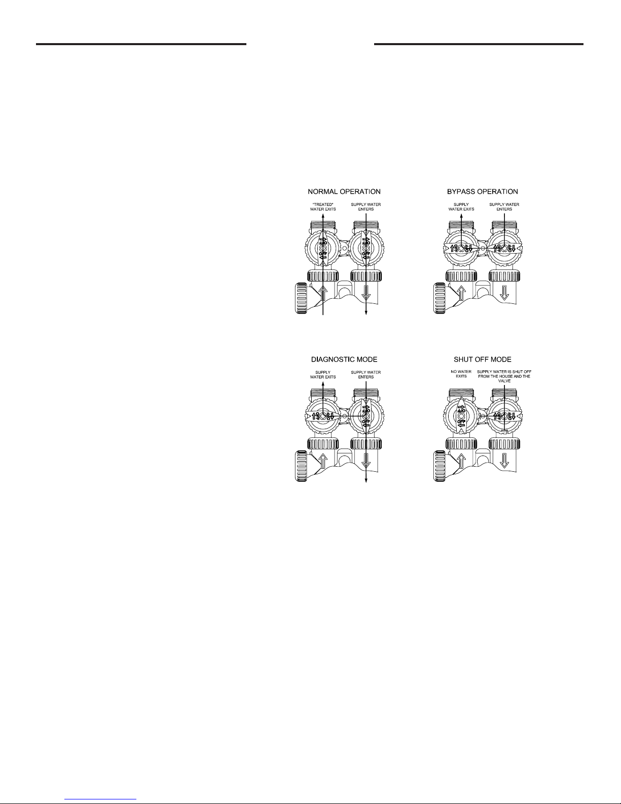
OPERATION:
1. Normal Operation Position: The inlet and outlet
handles point in the direction of ow indicated by the
engraved arrows on the control valve. Water ows
through the control valve during normal operation and
this position also allows the control valve to isolate the
media bed during the regeneration cycle. (see gure
1)
2. Bypass Position: The inlet and outlet handles
point to the center of the bypass, the control valve
is isolated from the water pressure contained in the
plumbing system. Untreated water is supplied to the
plumbing system. (see gure 2)
3. Diagnostic Position: The inlet handle points in
the direction of ow and the outlet handle points to
the center of bypass valve, system water pressure is
allowed to the control valve and the plumbing system
while not allowing water to exit from the control valve
to the plumbing. (see gure 3)
4. Shut Off Position: The inlet handle points to the
center of the bypass valve and the outlet handle
points in the direction of ow, the water is shut off
to the plumbing system. If water is available on the
outlet side of the lter it is an indication of water
bypass around the system (i.e. a plumbing connection
somewhere in the building bypasses the system).
(see gure 4)
The working parts of the bypass valve are the rotor assemblies that are contained under the bypass valve caps. Before working on the
rotors, make sure the system is depressurized. Turn the red arrow shaped handles towards the center of the bypass valve and back
several times to ensure rotor is turning freely.
The nuts and caps are designed to be unscrewed or tightened by hand. If necessary a pliers or the service spanner wrench can be
used to unscrew the nut or cap. Do not use a pipe wrench to tighten or loosen nuts or caps. Do not place screwdriver in slots on caps
and/or tap with a hammer.
Refer to page 15 for bypass valve parts diagram and page 16 for service spanner wrench information.
To access the rotor, unscrew the cap and lift the cap, rotor and handle out as one unit. Twisting the unit as you pull it out will help to
remove it more easily. There are three o-rings: one under the rotor cap, one on the rotor stem and the rotor seal. Replace worn
o-rings. Clean rotor. Reinstall rotor.
When reinstalling the red arrow handles be sure that:
1. The handle pointers are lined up with the control valve body arrows, and the rotor seal o-ring and retainer on both rotors face
to the right when being viewed from the front of the control valve; or
2. Arrows point toward each other in the bypass position.
Since the handles can be pulled off, they could be accidentally reinstalled 180° from their correct orientation. To install the red arrow
handles correctly, keep the handles pointed in the same direction as the arrows engraved on the control valve body while tightening the
bypass valve caps.
gure 1 gure 2
gure 3 gure 4
PAGE 4
Page 5
INSTALLATION INSTRUCTIONS
BRINE LINE FITTING CONNECTIONS
Click to buy NOW!
P
D
F
-
X
C
H
A
N
G
E
w
w
w
.
d
o
c
u
-
t
r
a
c
k
.
c
o
m
Click to buy NOW!
P
D
F
-
X
C
H
A
N
G
E
w
w
w
.
d
o
c
u
-
t
r
a
c
k
.
c
o
m
(All electrical & plumbing should be done in accordance to all local codes)
1. Place lter in desired location close to water supply inlet, after pressure tank, and near a source for waste water, (utility
sink, oor drain or sewer line). A 120V, 60Hz uninterrupted outlet is required. Keep lter far enough away from walls and
other obstructions to allow enough room for servicing the unit. If a water softener is also to be installed, generally it will be
placed in line after the neutralizer or lter.
From water supply neutralizer lter softener to service
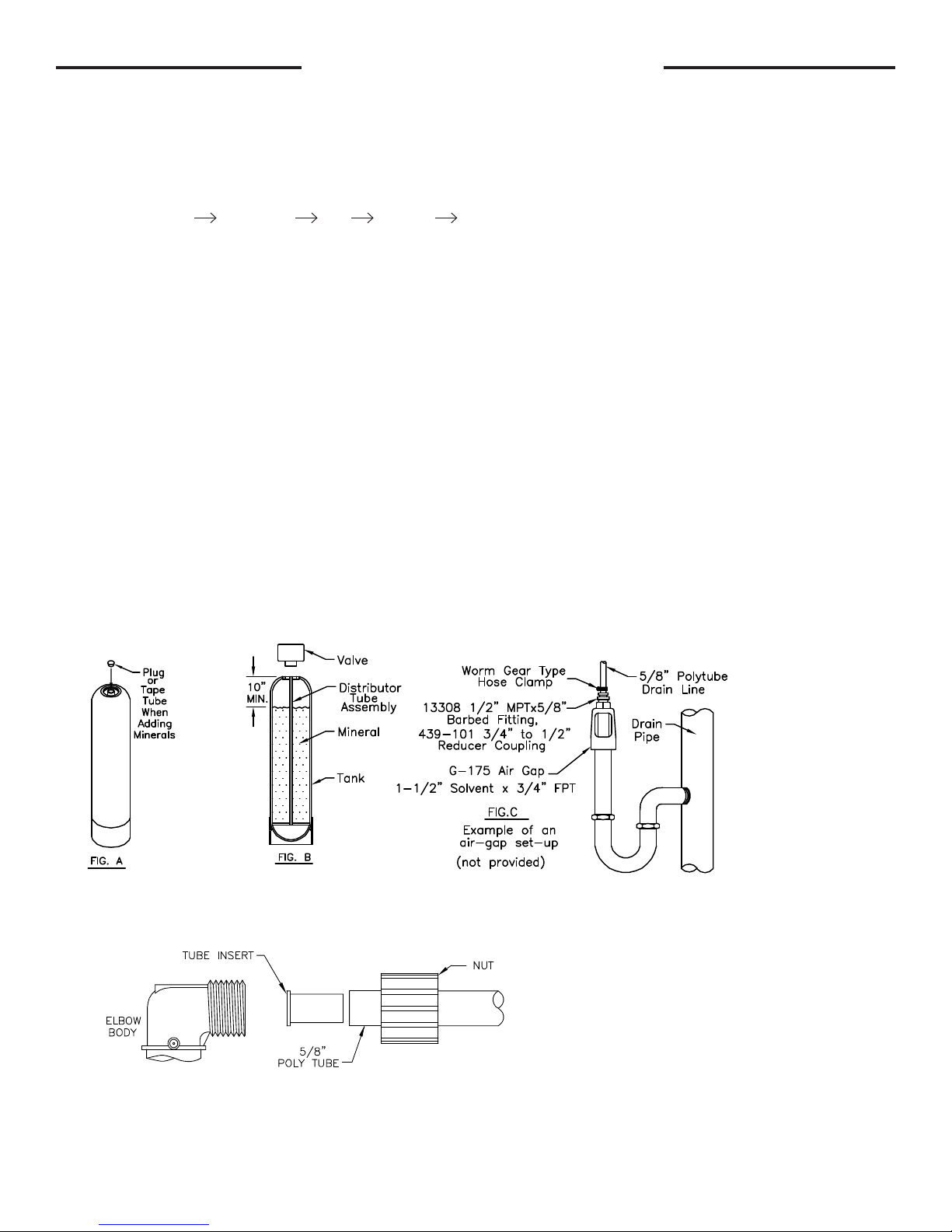
2. Add Minerals: Remove control valve from the mineral tank by turning counter-clockwise. Plug open end (top) of the
distributor tube assembly to prevent the mineral from entering (g. A). Add the mineral. DO NOT OVERFILL. Tanks should
be 2/3 full. Remove the plug from the distributor tube. Water can be manually added at this time to begin the mineral soaking
process. Replace the control valve making sure that the distributor tube is inserted into the center hole of the bottom of the
control valve.
3. Do all necessary plumbing (inlet to inlet, outlet to outlet, and drain line to drain). The control valve, ttings and/or bypass
are designed to accommodate minor plumbing misalignments but are not designed to support the weight of a system or the
plumbing.
4. When assembling the installation tting package (inlet and outlet), connect the tting to the plumbing system rst and then
attach the nut, split ring and o-ring. Heat from soldering or solvent cements may damage the nut, split ring or o-ring. Solder
joint should be cool and solvent cements should be set before installing the nut, split ring and o-ring. Avoid getting primer
and solvent cement on any part of the o-rings, split rings, bypass valve or control valve.
5. A jumper ground wire should be installed between the inlet and outlet pipe whenever the metallic continuity of a
water distribution piping system is interrupted. Install grounding strap on metal pipes.
6. The drain connection may be made using either 5/8” polytube (see below) or a 3/4” female adapter. The polytube insert
is shipped attached to the drain line elbow’s locking clip. Press the insert into the drain line tubing (tubing not provided).
Loosen the nut of the drain line elbow. Press the 5/8” polytube with insert into the drain line elbow until it seats on the back
of the tting. Tighten the nut. If soldering, joints near the drain must be done prior to connecting the drain line ow control
tting. Leave at least 6” between the drain line control tting and solder joints when soldering pipes that are connected on
the drain line control tting. Failure to do this could cause interior damage to the drain line ow control tting. Never insert a
drain line into a drain, sewer line, or trap. Always allow an air gap between the drain line and the wastewater to prevent the
possibility of sewage being back-siphoned into the lter (g. C).
DRAIN LINE FITTING CONNECTION USING 5/8" POLY TUBE
PAGE 5
Page 6
COLD
Click to buy NOW!
P
D
F
-
X
C
H
A
N
G
E
w
w
w
.
d
o
c
u
-
t
r
a
c
k
.
c
o
m
Click to buy NOW!
P
D
F
-
X
C
H
A
N
G
E
w
w
w
.
d
o
c
u
-
t
r
a
c
k
.
c
o
m
HOT
MINIMUM 10 FEET
BETWEEN
WATER FILTER OUTLET
AND
WATER H EATER INLET
BYPASS PLUMBING
RECOMMENDED
IF
OPTIONAL BP2000
BYPASS VALVE
IS NOT USED.
TO
OUTSIDE
TAP
LOCATE WATER FILTER CLOSE TO A DRAIN.
AVOID OVERHEAD DRAIN LINES IF POSSIBLE TO
PREVEN T BACK PRESSURE ON THE SYSTEM.
IF OVER HEAD DRAIN LINE IS USED AND EXCEEDS
5 FEET ABOVE CONNEC TION ON CONTROL VALVE
IF DRAIN LINE EXCEED S 20 FEET IN LENGTH,
OR BACK WASH RATES EXCEED 7 GPM,
DRAIN LINE PIPE SIZE SH OULD BE MINIMUM 3/4".
OR
DRAIN LINE
AIR GAP
ADAPTER
COLD
HOT
WATER
HEATER
MINIMUM 10 FEET
BETWEEN
WATER FILTER OUTLET
AND
WATER H EATER INLET
WATER FILTER
BYPASS PLUMBING
RECOMMENDED
IF
OPTIONAL BP2000
BYPASS VALVE
IS NOT USED.
TO
OUTSIDE
TAP
TO
DRAIN
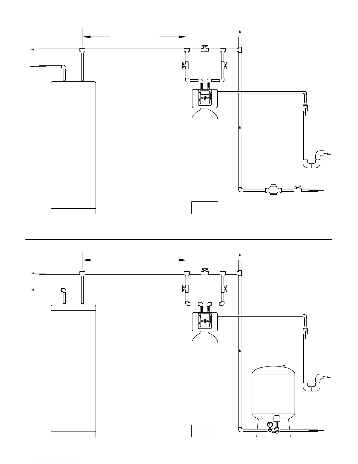
CITY WATER
INSTALLATION
WATER
METER
LOCATE WATER FILTER CLOSE TO A DRAIN.
AVOID OVERHEAD DRAIN LINES IF POSSIBLE TO
PREVEN T BACK PRESSURE ON THE SYSTEM.
IF OVER HEAD DRAIN LINE IS USED AND EXCEEDS
5 FEET ABOVE CONNEC TION ON CONTROL VALVE
IF DRAIN LINE EXCEED S 20 FEET IN LENGTH,
OR BACK WASH RATES EXCEED 7 GPM,
DRAIN LINE PIPE SIZE SH OULD BE MINIMUM 3/4".
OR
FROM
WATER MAIN
WATER
HEATER
PAGE 6
WATER FILTER
WELL WATER
INSTALLATION
PRESSURE
TANK
DRAIN LINE
AIR GAP
ADAPTER
TO
DRAIN
FROM
WELL PUMP
Page 7
7-LXCTAIR, 7-LXIMAIR INSTALLATION INSTRUCTIONS
TO
SERVICE
( WELL PUMP SYSTEM
"SUPPLY" GPM MUST
EQUAL OR EXCEED
AERATION SYSTEM
"SERVICE/BACKWASH" GPM )
FROM
WELL PUMP
PRESSURE
TANK
CHECK
VALVE
IN-LINE CHECK VALVE REQUIRED,
INSTALLED VERTICALLY PRIOR TO
AERATION SYSTEM
BUT AFTER ANY UNTREATED LINES.
AT LEAST 12" VERTICAL COLUMN
OF WATER PIPE ON TOP OF
CHECK VALVE BEFORE
AERATION SYSTEM.
AERATION
SYSTEM
A HOT WATER
THERMAL EXPANSION TANK
IS REQUIRED ON THE
COLD WATER INLET OF A
WATER HEATER.
UNTREATED LINE
A SMALL AMOUNT OF AIR MAY BECOME TRAPPED IN THE SERVICE LINE AFTER THE AERATION SYSTEM BACKWASHES.
A SPUTTERING OF AIR MAY BE NOTICED AT THE FIRST WATER FIXTURE TO BE USED AFTER THE SYSTEM BACKWASHES.
IF THIS IS OBJECTIONABLE, A CHECK VALVE CAN BE INSTALLED DIRECTLY AFTER THE AERATION SYSTEM.
NOTE: IF A CHECK VALVE IS INSTALLED BETWEEN A PRESSURE TANK AND A WATER HEATER, A HOT WATER EXPANSION TANK
IS REQUIRED ON THE COLD WATER INLET OF THE WATER HEATER.
Click to buy NOW!
P
D
F
-
X
C
H
A
N
G
E
w
w
w
.
d
o
c
u
-
t
r
a
c
k
.
c
o
m
Add mineral per instructions in this lter manual. Water can be manually added at this time to begin the mineral soaking
process.
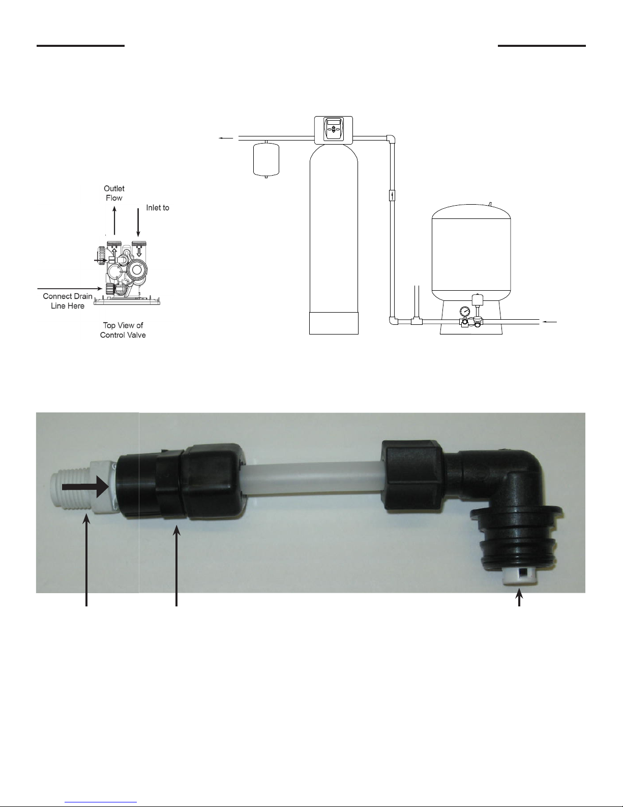
An in-line check valve is required, installed vertically prior to the aeration system, but after any untreated lines. Provide at
least a 12” vertical column of water pipe on top of the check valve before the aeration system. See diagram below.
IN-LINE CHECK VALVE REQUIRED,
INSTALLED VERTICALLY PRIOR TO
AERATION SYSTEM
BUT AFTER ANY UNTREATED LINES.
AT LEAST 12" VERTICAL COLUMN
OF WATER PIPE ON TOP OF
CHECK VALVE BEFORE
AERATION SYSTEM.
lter
TO
SERVICE
A HOT WATER
THERMAL EXPANSION TANK
IS REQUIRED ON THE
COLD WATER INLET OF A
WATER HEATER.
CHECK
VALVE
Check valve
connected here
(see below)
A check valve and a small piece of tubing is installed on the “brine elbow”. This must be in place to prevent water from
discharging during the backwash sequence. See diagram below.
A SMALL AMOUNT OF AIR MAY BECOME TRAPPED IN THE SERVICE LINE AFTER THE AERATION SYSTEM BACKWASHES.
A SPUTTERING OF AIR MAY BE NOTICED AT THE FIRST WATER FIXTURE TO BE USED AFTER THE SYSTEM BACKWASHES.
NOTE: IF A CHECK VALVE IS INSTALLED BETWEEN A PRESSURE TANK AND A WATER HEATER, A HOT WATER EXPANSION TANK
IF THIS IS OBJECTIONABLE, A CHECK VALVE CAN BE INSTALLED DIRECTLY AFTER THE AERATION SYSTEM.
IS REQUIRED ON THE COLD WATER INLET OF THE WATER HEATER.
AERATION
SYSTEM
PRESSURE
TANK
UNTREATED LINE
( WELL PUMP SYSTEM
"SUPPLY" GPM MUST
EQUAL OR EXCEED
AERATION SYSTEM
"SERVICE/BACKWASH" GPM )
FROM
WELL PUMP
Check Valve
212PPE
Adapter
P6FC4
Follow installation instruction in this manual for plumbing the inlet and outlet.
Special precautions must be made when connecting the drain line. Hard piping is
recommended. During backwash, air and water escape quickly, causing a exible drain line to
whip and thrash. Attach the drain line securely to an air gap device on the waste water line.
Brine elbow connected
to control valve using
locking clip
PAGE 7
Page 8
PLACING FILTER INTO SERVICE
Do not plug the transformer into the receptacle yet. Make sure inlet and outlet valves are to their closed positions. If using
optional bypass, place in bypass position. Turn on main water supply. Open a cold water faucet. This will clear the line
of any debris (solder, pipe dope, etc.) that may be in the line. Let water run at faucet for a couple minutes, or until clear.
Turn off faucet. Now plug the transformer into a 120 volt receptacle (be certain the receptacle is uninterrupted). Within 5
seconds the control display and buttons will illuminate and the time of day screen will appear.
• Press and hold the
REGEN
button for approximately 5 seconds until the motor starts.
• Wait until display reads BACKWASH and numbers start counting down. (7-LXCTAIR and 7-LXIMAIR models will
have an AIR RELEASE cycle for 5 seconds then BACKWASH will appear.)
If using optional bypass SLOWLY turn bypass valve to DIAGNOSTIC position (See gure 3 on page 4) or slowly open
inlet valve to allow water to slowly enter lter.
Mineral is dry, and lling to quickly with water will result in the mineral plugging the drain line and valve
assembly. Some minerals such as carbon and Filter Ag should not be backwashed immediately for extended
periods of time. These minerals need to soak in water for a 24-hour period before backwashing at full ow. Flow
water to drain very slowly, increasing the ow until the water runs clear.
FOR 7-LXCTAIR, 7-LXIMAIR MODELS-
Momentarily press
REGEN
again. Display will read REGENERANT DRAW DN; allow this cycle to complete. This allows an
air pocket to form for the lter to function properly. Control will automatically advance to the FILTERING position. Open the
outlet valve of the lter, or if using optional bypass place to NORMAL OPERATION MODE (see gure 1 on page 4).
FOR ALL OTHER FILTERS-
When water is owing steadily to drain without the presence of air, momentarily press
REGEN
again. Display will read
RINSE. Open the outlet valve of the lter, or if using optional bypass place to NORMAL OPERATION MODE (see gure
1 on page 4). Allow control to nish the RINSE cycle. Allow the control to automatically advance to the FILTERING
position.
GENERAL OPERATION
Note: As an energy saving feature, the control will automatically turn off all SOLID BLUE or SOLID GREEN
display illumination and keypad illumination after about 5 minutes of the last keypad button push. Any further
keypad touch will cause the re-illumination of the display and keypad, and re-activate keypad control.
User Displays
When the system is in normal service mode, one of up to four available User Displays will be shown. Pressing
alternate between the following displays:
• Current time of day
• Treated water ow rate
• Service contact name and phone number (if entered)
• Remaining days to regeneration (if Day Override is
programmed)
To clear the Service Call reminder, press the and buttons simultaneously while the number and banner text
screen is displayed.
If the system has called for a backwash that will occur at the preset time of backwash, the words REGEN TODAY will
alternate with the header on the display.
Utilizing the control valve’s built-in water meter, a water drop ashes on the display when water is being treated (i.e. water
is owing through the system).
NEXT
will
PAGE 8
Page 9

SET TIME OF DAY
Current time of day needs to be entered during initial installation, and adjusted when daylight saving time begins or ends.
If an extended power outage occurs and depletes the on-board non-rechargeable coin cell battery, when power resumes
the time of day should be reset and battery replaced.
STEP 1
STEP 2
STEP 1 – Press
STEP 2 - Current Time (hour): Set the hour of the day using or buttons. AM/PM toggles
after 12. Press
STEP 3
STEP 3 - Current Time (minutes): Set the minutes of the day using or buttons. Press
NEXT to exit Set Time of Day. Press
RETURN TO NORMAL MODE
CLOCK
NEXT
to go to Step 3.
to return to previous step.
REGEN
ADJUST DAYS BETWEEN BACKWASH,
OR TIME OF BACKWASH
STEP 1
STEP 2
STEP 3
STEP 1 - Press
NEXT
and simultaneously for 3 seconds to access Installer Display Settings.
STEP 2 – Day Override: Set the maximum number of days between backwashes (REGEN). If
value set to “OFF”, backwash initiation is based solely on volume used. If value is set as a number
(allowable range from 1 to 28) a backwash initiation will be called for on that day even if sufcient
volume of water were not used to call for a backwash. Set Day Override using or buttons:
• number of days between backwash (1 to 28); or
• “OFF”.
For 7-LXCTAIR and 7-LXIMAIR models,
STEP 2 Day Override is strongly recommended - to be set at 1 for daily backwashing in order to replenish the air pocket.
Press
NEXT
to go to step 3. Press
REGEN
to return to previous step.
STEP 3 – Next Regeneration Time (hour): Set the hour of day for backwash using or
buttons. AM/PM toggles after 12. The default time is 12:00 AM (midnight). Press
Step 5. Press
REGEN
to return to previous step.
NEXT
to go to
PAGE 9
Page 10

STEP 5
STEP 5 – Next Regeneration Time (minutes): Set the minutes of day for backwash using
or buttons. Press
NEXT
to return to normal operation. Press
REGEN
to return to
previous step.
RETURN TO NORMAL MODE
LOW BATTERY
A non-rechargeable coin cell battery is located on the circuit board, used only to maintain the time of day during power
outages (all other information will be stored in memory no matter how long the power outage). The screen displays LOW
BATTERY when the battery needs to be replaced. The screen will remain illuminated solid blue when LOW BATTERY is
displayed. Initially LOW BATTERY display will alternate with the User display, nally displaying only LOW BATTERY. User
displays are still accessible by pressing
NEXT
.
CONTACT SCREEN PROGRAMMING
STEP 1
STEP 1 - Press
Settings.
NEXT
and simultaneously for 3 seconds to access Installer Display
STEP 2
STEP 3
STEP 2 - Press
From Step 3, while hour is ashing, press and hold both the
NEXT
to go to step 3.
CLOCK
and button to
change phone number and banner text.
Phone Number - Set phone number using the or arrow. Press
to the next digit. Press
REGEN
to return to previous digit.
NEXT
to forward
Banner Text - Set the banner text up to a maximum of 44 characters. Use the or
to select letters of the alphabet, numbers, ampersand (&), or a space in the banner text.
Press
NEXT
to forward to the next character or to exit the Installer Display Settings.
PAGE 10
Page 11

X-FACTOR FRONT COVER AND DRIVE ASSEMBLY
Drawing No. Order No. Description Quantity
1
2 V3107-01 Motor 1
3 V3106-01 Drive Bracket & Spring Clip 1
4 V3757LP-BOARD PC Board 1
5 V3110 Drive Gear 12x36 3
6 V3109 Drive Gear Cover 1
V3692-02LW LP Front Cover Assembly
1
When replacing the battery, align
positives and push down to fully seat.
Battery Fully Seated
AC Adapter
Order No.
(Not shown)
V3186
Supply Voltage 120V AC
Supply Frequency 60 Hz
Output Voltage 12V AC
Output Current 500 mA
Correct
Battery
Orientation
1
Battery replacement is
3 volt lithium coin cell
type 2032.
4
5
After completing any valve maintenance involving the drive assembly or the drive cap assembly and pistons, unplug
power source jack from the printed circuit board (black wire) and plug back in or press and hold
for 3 seconds. This resets the electronics and establishes the service piston position. The display should ash the
software version and then reset the valve to the service position.
Refer to page 18 for detailed service instructions.
PAGE 11
6
2
NEXT
and
3
REGEN
buttons
Page 12

1
2
3
4
5
DRIVE CAP ASSEMBLY, DOWNFLOW PISTON,
REGENERANT PISTON AND SPACER STACK ASSEMBLY
Drawing
Order No. Description Qty
No.
1 V3005 Spacer Stack Assembly 1
2 V3004 Drive Cap Assy 1
3 V3178LP Back Plate 1
4 V3011 Piston Downow Assy 1
5* V3174 Regenerant Piston 1
6 V3135 O-ring 228 1
7 V3180 O-ring 337 1
8 V3105 O-ring 215 (Distributor Tube) 1
Not Shown V3001 Body Assy Downow 1
*Only used with 7-LXCTAIR and 7-LXIMAIR models.
After completing any valve
maintenance involving the drive
assembly or the drive cap assembly
and pistons, unplug power source jack
from the printed circuit board (black
wire) and plug back in or press and
hold
NEXT
and
REGEN
buttons for 3
2
seconds. This resets the electronics
and establishes the service piston
position. The display should ash the
software version and then reset the
valve to the service position.
Refer to pages 18-20 for detailed
service instructions.
Do not use Vaseline, oils, other hydrocarbon lubricants
or spray silicone anywhere. A silicone lubricant may be
used on black o-rings but is not necessary. Avoid any
type of lubricants, including silicone, on the clear
lip seals.
3
1
5
*
4
7
6
8
INJECTOR CAP, INJECTOR SCREEN, INJEECTOR, PLUG AND O-RING
Drawing No. Order No. Description Qty
1 V3176 INJECTOR CAP 1
2 V3152 O-RING 135 1
3 V3177-01 INJECTOR SCREEN CAGE 1
4 V3010-1Z INJECTOR ASSY Z PLUG 1
†
5
Not Shown V3170 O-RING 011 *
Not Shown V3171 O-RING 013 *
* The injector plug and the injector each contain one 011 (lower) and 013 (upper)
o-ring.
†
†
Only used with 7-LXCTAIR and 7-LXIMAIR Models. For all other models, a second
V3010-1Z injector assy Z plug is used.
The nut and caps are designed to be unscrewed or tightened by hand or with
the service spanner wrench (see page 16). If necessary a pliers can be used to
unscrew the nut or cap. Do not use a pipe wrench to tighten or loosen nuts or caps.
Do not place a screwdriver in slots on caps and/or tap with a hammer.
Refer to page 20 for detailed service instructions.
V3010-1C INJECTOR ASSY C VIOLET
1V3010-1F INJECTOR ASSY F BLUE
V3010-1H INJECTOR ASSY H GREEN
PAGE 12
Page 13

BRINE REFILL PLUG
Drawing No. Order No. Description Qty
1 H3195 Rell Port Plug Assy 1
2 H4615 Elbow Locking Clip 1
For 7-LXCTAIR and 7-LXIMAIR models, refer to page 7
for diagram.
WATER METER
Drawing No. Order No. Description Qty
1 V3151 Nut 1” QC 1
2 V3003* Meter Assy 1
3 V3118-01 Turbine Assy 1
4 V3105 O-ring 215 1
*Order number V3003 includes V3118-01 Turbine
Assy and V3105 O-ring 215.
THIS WATER METER SHOULD NOT BE USED AS THE PRIMARY MONITORING
DEVICE FOR CRITICAL OR HEALTH EFFECT APPLICATIONS.
The nut and caps are designed to be unscrewed or tightened by hand or with the
service spanner wrench (see page 16). If necessary a pliers can be used to unscrew
the nut or cap. Do not use a pipe wrench to tighten or loosen nuts or caps. Do not
place a screwdriver in slots on caps and/or tap with a hammer.
Refer to page 20 for detailed service instructions.
PAGE 13
Page 14

DRAIN LINE - 3/4”
Dwg
No.
Order No. Description Qty
1 H4615 Elbow Locking Clip 1
2 V3194 Polytube insert 5/8 Option
3 V3192 Nut ¾ Drain Elbow Option
4* V3158 Drain Elbow ¾ Male 1
5 V3163 O-ring 019 1
4
6* V3159 DLFC Retainer Assy 1
V3162-007 DLFC 0.7 gpm for ¾
V3162-010 DLFC 1.0 gpm for ¾
V3162-013 DLFC 1.3 gpm for ¾
V3162-017 DLFC 1.7 gpm for ¾
V3162-022 DLFC 2.2 gpm for ¾
V3162-027 DLFC 2.7 gpm for ¾
V3162-032 DLFC 3.2 gpm for ¾
7
V3162-042 DLFC 4.2 gpm for ¾
V3162-053 DLFC 5.3 gpm for ¾
V3162-065 DLFC 6.5 gpm for ¾
V3162-075 DLFC 7.5 gpm for ¾
One
DLFC
must
be
used
if ¾
tting
is
used
Water
Proper DLFC orientation
directs water ow towards
the washer face with
rounded edge.
Flow
V3162-090 DLFC 9.0 gpm for ¾
V3162-100 DLFC 10.0 gpm for ¾
*4 and 6 can be ordered as a complete assembly V3331 Drain Elbow and Retainer Assy
Do not use pipe dope or other sealants on threads. Teon tape must be used on threads of 3/4” NPT connection (unless
using 5/8” polytubing).
Do not use Vaseline, oils, other hydrocarbon lubricants or spray silicone anywhere. A silicone lubricant may be used on
black o-rings but is not necessary.
DRAIN LINE - 1”
Dwg
* Can be ordered as a set. Order number V3008-02,
description: Drain FTG 1” Straight.
Order No. Description Qty
No.
1 H4615 Elbow Locking Clip 1
2 V3008-02 Drain FTG 1” Straight 1
3* V3166 Drain FTG Body 1” 1
4* V3167 Drain FTG Adapter 1” 1
5* V3163 O-ring 019 1
6* V3150 Split Ring 1
7* V3151 Nut 1” QC 1
8* V3105 O-ring 215 1
V3190-090 DLFC 9.0 gpm for 1” One
V3190-100 DLFC 10.0 gpm for 1”
V3190-110 DLFC 11.0 gpm for 1”
V3190-130 DLFC 13.0 gpm for 1”
V3190-150 DLFC 15.0 gpm for 1”
9
V3190-170 DLFC 17.0 gpm for 1”
V3190-200 DLFC 20.0 gpm for 1”
V3190-250 DLFC 25.0 gpm for 1”
DLFC
must
be
used
if 1”
tting
is
used
Water
Flow
Proper DLFC orientation
directs water ow towards
the washer face with
rounded edge.
PAGE 14
Page 15

INSTALLATION FITTING ASSEMBLIES
Description: Fitting 1” PVC Male NPT Elbow
Order No: V3007 (Standard)
Assembly
Drawing
Order
No.
No.
1 V3151 Nut 1” Quick Connect 2
2 V3150 Split Ring 2
3 V3105 O-Ring 215 2
4 V3149
Description Quantity
Fitting 1 PVC Male
NPT Elbow
2
Description: Fitting Vertical Adapter Assembly
Order No. V3191-01 (Optional)
Drawing
Order
No.
No.
1 V3151 Nut 1” Quick Connect 2
2 V3150 Split Ring 2
3 V3105 O-Ring 215 2
4 V3191 Vertical Adapter 2
3
Description Quantity
2
1
4
Do not use pipe dope or other sealants on threads. Teon tape must be used on threads of 1” NPT connection. Teon
tape is not necessary on the nut connection nor caps because of o-ring seals.
The nut and caps are designed to be unscrewed or tightened by hand or with the service spanner wrench (see page 16).
If necessary a pliers can be used to unscrew the nut or cap. Do not use a pipe wrench to tighten or loosen nuts or caps.
Do not place a screwdriver in slots on caps and/or tap with a hammer.
Do not use Vaseline, oils, other hydrocarbon lubricants or spray silicone anywhere. A silicone lubricant may be used on
black o-rings but is not necessary.
BYPASS VALVE
(Order No. BP2000)
Drawing No. Order No. Description Qty
1 V3151 Nut 1” Quick Connect 2
2 V3150 Split Ring 2
3 V3105 O-Ring 215 2
4 V3145 Bypass 1” Rotor 2
5 V3146 Bypass Cap 2
6 V3147 Bypass Handle 2
7 V3148 Bypass Rotor Seal Retainer 2
8 V3152 O-ring 135 2
9 V3155 O-ring 112 2
10 V3156 O-ring 214 2
Refer to page 4 for detailed operation and service instructions.
PAGE 15
Page 16

SERVICE SPANNER WRENCH
(Order No. V3193)
Although no tools are necessary to assemble or disassemble the valve, the wrench (shown in various positions on the
valve) may be purchased to aid in assembly or disassembly.
Loosens Injector And
Bypass Caps
Loosens Drive Cap
PAGE 16
Page 17

1 1/4 NPT
1 1/4 NPT
1 BSPT
CHANGE
CHANGE
R
BY:
LTR
DATE:
TITLE:
DATE
SCALE:
PART #:
REV.
DWG #:
Clack Corporation
4462 DURAFORM LANE, WINDSOR, WI 53598
TELEPHONE NO. 1-608-846-3010
C
C
1:2
12/1/05
D.A.K.
WS1F1_1-2&Sol1_1-4_0707
MODEL:
DWG:
WS1F1_1-2&Sol1_1-4_0707
CONFIG:
exploded-(artwork)
SHEET:
1 OF 1
WS1 ADAPTER 1 1/2 & 1 1/4 SOLVENT ASSEMBLY
OPTIONAL INSTALLATION FITTING ASSEMBLIES
Description: Fitting ¾” & 1” PVC Solvent 90°
Drawing
No.
1 V3151 Nut 1” Quick Connect 2
2 V3150 Split Ring 2
3 V3105 O-Ring 215 2
4 V3189
Order No: V3007-01
Assembly
Order
No.
Description Quantity
Fitting ¾&1 PVC
Solvent 90
2
Order No: V3007-02
Description: Fitting 1” Brass Sweat
Assembly
Drawing
Do not install in California.
No.
Order
No.
Description Quantity
1 V3151 Nut 1” Quick Connect 2
2 V3150 Split Ring 2
3 V3105 O-Ring 215 2
4 V3188
Fitting 1 Brass Sweat
Assembly
Description: Fitting ¾” Brass Sweat
Drawing
No.
1 V3151
2 V3150 Split Ring 2
2
3 V3105 O-Ring 215 2
4 V3188-01
Do not install in California.
Order No: V3007-03
Assembly
Order No. Description Quantity
Nut 1” Quick
Connect
Fitting ¾ Brass
Sweat
2
2
Description: Fitting 1” Plastic Male NPT
Description: Fitting 1-¼” Plastic Male NPT
Assembly
Order No: V3007-04*
Drawing
3
No.
Order
No.
Description Quantity
1 V3151 Nut 1” Quick Connect 2
2 V3150 Split Ring 2
3 V3105 O-Ring 215 2
4 V3164
Fitting 1" Plastic Male
NPT
1
2
4
1 NPT
Drawing
No.
1 V3151 Nut 1” Quick Connect 2
2 V3150 Split Ring 2
3 V3105 O-Ring 215 2
2
4 V3317
3
Order No: V3007-05
Assembly
Order
No.
Fitting 1-¼" Plastic
Male NPT
1
2
Description Quantity
2
4
Description: Fitting 1¼” & 1½” PVC Solvent
Drawing
No.
1 V3151 Nut 1” Quick Connect 2
2 V3150 Split Ring 2
3 V3105 O-Ring 215 2
4 V3352 Fitting 1¼”&1½” PVC
3
Order No. V3007-07*
Assembly
Order
No.
Solvent
1
2
Description Quantity
4
2
Description: Fitting 1¼” & 1½” Brass Sweat
Assembly
Drawing
No.
Order
No.
Description Quantity
1 V3151 Nut 1” Quick Connect 2
2 V3150 Split Ring 2
3 V3105 O-Ring 215 2
1
2
Fitting 1¼" & 1½"
Brass Sweat
4
4 V3375
3
2
*Must be special ordered. Minimum quantity of 24
Order No: V3007-09*
Description: Fitting 3/4" Brass SharkBite
Order No. V3007-12
Assembly
Drawing
No.
Order
Description Quantity
No.
1 V3151 Nut 1" Quick Connect 2
2 V3150 Split Ring 2
3 V3105 O-Ring 215 2
4 V3628 Ftg 3/4 Brass Shark-
Bite
1
4
2
3
PAGE 17
Description: Fitting 1" Brass SharkBite
Order No. V3007-13*
Assembly
Drawing
2
No.
Order
No.
Description Quantity
1 V3151 Nut 1" Quick Connect 2
2 V3150 Split Ring 2
3 V3105 O-Ring 215 2
4 V3629 Ftg 1" Brass Shark-
Bite
1
4
2
3
2
Page 18

SERVICE INSTRUCTIONS
ACID NEUTRALIZERS, (7-LXDAN-): Mineral used: Calcite. Calcite will dissolve in proportion to the amount of acid in the raw water.
The amount of calcite in the tank should be monitored and replaced periodically. A tank with a dome plug is provided so that calcite
may be added without removing the control valve. To check level of calcite in the mineral tank shut off water supply to the lter. Press
and hold the
Remove hexagonal dome plug. A small amount of water will be lost from the tank. Insert a dipstick into the dome hole until the stick
reaches mineral level. Mark and remove the stick. Measure the marked distance on the stick. This number should never be less than
10”. Replace calcite before the mineral level is 24” from the dome hole. Adding calcite will displace the water in the tank. This water may
be siphoned out to reduce spillage. As each installation will use a different amount of calcite, monitoring the mineral level once a month
for the rst few months of operation should give a fairly good indication as to how frequently the calcite will need to be replenished.
Replace the dome plug. Slowly turn on the water supply to the neutralizer. Allow water to run to drain for a couple of minutes to allow
“Fines” to backwash to drain. Plug valve into power supply.
A pH test kit may also be used to monitor the pH level to help determine when mineral needs to be replenished. Calcite will add
approximately four (4) or more grains per gallon to the original hardness of the raw water. This should be kept in mind when
guring regeneration cycle for a water softener. If a Corosex/Calcite mixture is recommended to be used (for high ow rates or very low
pH level), mix one part Corosex with four parts Calcite BEFORE adding to the tank. NOTE: 1 cu ft. of calcite = 85 lbs.
IRON FILTERS, (7-LXIM-, 7-LXIMAIR-): Mineral used: Birm. No chemical regenerant is required, backwash periodically. No hardness
is added to the water. For clear water iron, when the pH is less than seven (7) in the raw water, a water softener should be used in
place of the iron lter. Note: When using Birm for iron removal, it is necessary that the water: contain no oil or hydrogen sulde,
organic matter not to exceed 4-5 ppm, the D.O. content equal at least 15% of iron content with a pH of 6.8 or more. If the inuent water
has a pH of less that 6.8, neutralizing additives such as Calcite, Corosex or soda ash may be used prior to the Birm lter to raise the
pH. A water having a low D.O. level may be pretreated by aeration (1-LXIMAIR-). Chlorination greatly reduces Birm’s activity. High
concentrations of chlorine compounds may deplete the catalytic coating.
COLOR, TASTE AND ODOR FILTERS, (7-LXCT-, 1-LXCTAIR-): Mineral used: Carbon. Used for removal of chlorine, color, taste, odor
and low levels of sulfur, etc. The mineral bed should be backwashed periodically, but will in time reach the maximum absorbency. When
this occurs the carbon should be completely replaced. For removal of chloramines, stronger levels of sulfur, and even iron, special
catalytic carbon is recommended. When catalytic carbon is used for sulfur and iron removal, pretreatment by aeration is recommended
to ensure 4 ppm of D. O. (7-LXCTAIR-).
SEDIMENT AND TURBIDITY, (7-LXST-): Mineral used: Filter AG. This lter will lter out dirt, silica, etc. down to the 20-40
micron range. In most cases it has a lifetime ll and should be backwashed periodically depending on local conditions. Pressure drop is
very low.
DRIVE ASSEMBLY (refer to pages 11&12 for diagrams):
Remove the valve cover to access the drive assembly.
Disconnect the power source plug (black wire) from the PC board prior to disconnecting the motor or water meter plugs from the PC
board. The power source plug connects to the four-pin jack. The motor plug connects to the two-pin jack on the left-hand side of the PC
board. The water meter plug (gray wire) connects to the three-pin jack on the far right-hand side of the PC board.
The PC board can be removed separately from the drive bracket but it is not recommended. Do not attempt to remove the display panel
from the PC board. Handle the board by the edges. To remove the PC board from the drive bracket, unplug the power, water meter and
motor plugs from the PC board. Lift the middle latch along the top of the drive bracket while pulling outward on the top of the PC board.
The drive bracket has two plastic pins that t into the holes on the lower edge of the PC board. Once the PC board is tilted about 45°
from the drive bracket it can be lifted off of these pins. To reinstall the PC board, position the lower edge of the PC board so that the
holes in the PC board line up with the plastic pins. Push the top of the PC board towards the valve until it snaps under the middle latch,
weave the power and water meter wires into the holders and reconnect the motor, water meter and power plugs.
The drive bracket must be removed to access the drive cap assembly and pistons or the drive gear cover. It is not necessary to remove
the PC board from the drive bracket to remove the drive bracket. To remove the drive bracket start by removing the plugs for the power
source and the water meter. Unweave the wires from the side holders. Two tabs on the top of the drive back plate hold the drive bracket
in place. Simultaneously lift the two tabs and gently ease the top of the drive bracket forward. The lower edge of the drive bracket has
two notches that rest on the drive back plate. Lift up and outward on the drive bracket to disengage the notches.
To reassemble, seat the bottom of the drive bracket so the notches are engaged at the bottom of the drive back plate. Push the top of
the drive bracket toward the two latches. The drive bracket may have to be lifted slightly to let the threaded piston rod pass through
the hole in the drive bracket. Maintain a slight engaging force on top of the drive bracket while deecting the bracket slightly to the left
by pressing on the side of the upper right corner. This helps the drive gears mesh with the drive cap assembly. The drive bracket is
properly seated when it snaps under the latches on the drive back plate. If resistance is felt before latching, then notches are not fully
engaged, the piston rod is not in hole, the wires are jammed between the drive bracket and drive back plate, or the gear is not engaging
the drive cap assembly.
To inspect the drive gears, the drive gear cover needs to be removed. Before trying to remove the gear cover, the drive bracket must
be removed from the drive back plate. (Refer to the instructions above regarding removing the drive bracket from the drive back plate.
The drive gear cover can be removed from the drive bracket without removing the motor or the PC board.) The drive gear cover is held
in place on the drive bracket by three clips. The largest of the three clips is always orientated to the bottom of the drive bracket. With
the PC board facing up, push in and down on the large clip on the drive gear cover. Handle the cover and the gears carefully so that the
gears do not fall off the pegs in the cover.
REGEN
button until the lter goes into backwash. Unplug valve from power supply. This will relieve the pressure in the tank.
PAGE 18
Page 19

Replace broken or damaged drive gears. Do not lubricate any of the gears. Avoid getting any foreign matter on the reective coating
because dirt or oils may interfere with pulse counting.
The drive gear cover only ts on one way, with the large clip orientated towards the bottom. If all three clips are outside of the gear
shroud on the drive bracket the drive gear cover slips easily into place.
The drive bracket does not need to be removed from the drive plate if the motor needs to be removed. To remove the motor, disconnect
the power and motor plugs from the jacks on the PC board. Move the spring clip loop to the right and hold. Rotate the motor at least a
¼ turn in either direction so the wires are vertical (up & down) before gently pulling on the wire connectors to remove the motor. Pulling
directly on the wires without rotating the motor may break the wires off the motor.
Replace the motor if necessary. Do not lubricate the motor or the gears. To reinstall the motor, move the spring clip loop to the right and
hold. Gently turn the motor while inserting so that the gear on the motor meshes with the gears under the drive gear cover. Release the
spring clip loop and continue to rotate the motor until the wires are horizontal and the motor housing engages the small plastic bulge
inside the drive bracket motor retainer. Reconnect the motor plug to the two-pronged jack on the lower left side of the PC board. If the
motor will not easily engage with the drive gears when reinstalling, lift and slightly rotate the motor before reinserting. Reconnect the
power plug.
Replace the valve cover. After completing any valve maintenance involving the drive assembly or the drive cap assembly and pistons,
unplug power source jack from the printed circuit board (black wire) and plug back in or press and hold
NEXT
and
REGEN
buttons for 3
seconds.
This resets the electronics and establishes the service piston position. The display should ash the software version and then reset the
valve to the service position.
DRIVE CAP ASSEMBLY, MAIN PISTON AND (refer to page 11&12 for diagrams):
The drive assembly must be removed to access the drive cap assembly. The drive cap assembly must be removed to access the
piston(s). The drive cap assembly is threaded into the control valve body and seals with an o-ring. To remove the drive cap assembly
use the special plastic service spanner wrench (see page 16) or insert a ¼” to ½” at blade screwdriver into one of the slots around the
top 2” of the drive cap assembly so it engages the notches molded into the drive back plate around the top 2” of the piston cavity. See
gure below. The notches are visible through the holes. Lever the screwdriver so the drive cap assembly turns counter clockwise. Once
loosened unscrew the drive cap assembly by hand and pull straight out.
The drive cap assembly contains the drive cap, the main drive gear, drive cap spline, piston rod and various other parts that should not
be dissembled in the eld. The only replaceable part on the drive cap assembly is the o-ring. Attached to the drive cap assembly is the
main piston (and a regenerant piston for 7-LXCTAIR and 7-LXIMAIR models).
The regenerant piston (the small diameter one behind the main piston found only the 7-LXIMAIR models is removed from the main
piston by pressing sideways and unsnapping it from its latch. Chemically clean in dilute sodium bisulte or vinegar, or replace the
regenerant piston if needed. To remove the main piston fully extend the piston rod and then unsnap the main piston from its latch by
pressing on the side with the number. Chemically clean in dilute sodium bisulte or vinegar, or replace the main piston.
Reattach the main piston to the drive cap assembly. Reattach the regenerant piston (if needed) to the main piston. Reinsert the drive
cap assembly and piston into the spacer stack assembly and hand tighten the drive cap assembly. Continue to tighten the drive cap
assembly using a screwdriver as a ratchet until the black o-ring on the spacer stack assembly is no longer visible through the drain port.
Excessive force can break the notches molded into the drive back plate. Make certain that the main drive gear still turns freely. The
exact position of the piston is not important as long as the main drive gear turns freely.
Reattach the drive assembly to the control valve and connect all plugs. After completing any valve maintenance involving the drive
assembly or the drive cap assembly and pistons, unplug power source jack from the printed circuit board (black wire) and plug back in
or press and hold
NEXT
and
REGEN
buttons for 3 seconds.
This resets the electronics and establishes the service piston position. The display should ash the software version and then reset the
valve to the service position.
PAGE 19
Page 20

REFILL FLOW CONTROL ASSEMBLY (refer to page 7 for diagrams):
To clean or replace the rell ow control, pull out the elbow-locking clip and then pull straight up on the elbow. Replace the elbow
locking clip in the slot so that it is not misplaced. Twist to remove the white ow control retainer. The ow control can be removed by
prying upward through the side slots of the retainer with a small at blade screwdriver.
Chemically clean the ow control or the white ow control retainer using dilute sodium bisulte or vinegar. Do not use a wire brush. If
necessary, replace the ow control, o-ring on the ow control retainer, or the o-ring on the elbow.
Reset the ow control so the rounded end is visible in the ow control. Reset the white ow control retainer by pushing the retainer into
the elbow until the o-ring seats. Remove locking clip, push down on elbow to reset and insert locking clip.
Do not use Vaseline, oils, or other unacceptable lubricants on o-rings. A silicone lubricant may be used on the o-ring on the elbow or the
white retainer.
SPACER STACK ASSEMBLY (refer to page 12 for diagrams):
To access the spacer stack assembly remove the drive assembly, drive cap assembly and piston. The spacer stack assembly can be
removed easily without tools by using thumb and forenger. Inspect the black o-rings and clear lip seals for wear or damage. Replace
the entire stack if necessary. Do not disassemble the stack.
The spacer stack assembly may be chemically cleaned (dilute sodium bisulte or vinegar) or wiped with a soft cloth.
The spacer stack assembly can be pushed into the control valve body bore by hand. Since the spacer stack assembly can be
compressed it is easier to use a blunt object (5/8” to 1-1/8” in diameter) to push the center of the assembly into the control valve body.
The assembly is properly seated when at least four threads are exposed (approximately 5/8”). Do not force the spacer stack assembly
in. The control valve body bore interior can be lubricated with silicone to allow for easy insertion of the entire stack.
Reattach the drive cap assembly and piston(s) and the drive assembly.
After completing any valve maintenance involving the drive assembly or the drive cap assembly and pistons, unplug power source jack
from the printed circuit board (black wire) and plug back in or press and hold
NEXT
and
REGEN
buttons for 3 seconds.
This resets the electronics and establishes the service piston position. The display should ash the software version and then reset the
valve to the service position.
INJECTOR CAP, SCREEN, INJECTOR PLUG, AND INJECTOR (refer to page 12 for diagram):
Unscrew the injector cap and lift off. Loosen cap with special plastic service spanner wrench (see page 16) or pliers if necessary.
Attached to the injector cap is a screen. Remove the screen and clean if fouled.
The plug and/or injector can be pried out with a small screwdriver. The plug can be wiped clean. If the plug leaks replace the entire
plug. The injector consists of a throat and a nozzle. Chemically clean the injector with vinegar or sodium bisulte. The holes can be
blown out with air. Both pieces have small diameter holes that control the ow rates of water to insure that the proper concentration
of regenerant is used. Sharp objects, which can score the plastic, should not be used to clean the injector. Scoring the injector or
increasing the diameter of the hole could change the operating parameters of the injector.
For 7-LXCTCIR and 7-LXIMAIR models, push the plug in the hole marked “UP” and the injector in the hole marked “DN”.
For all other models, push the plugs in the holes marked “UP” and “DN”.
Replace the screen and hang tighten the injector cap.
WATER METER (refer to page 13 for diagrams):
The water meter assembly is connected to the PC board by a wire. If the entire water meter assembly is to be replaced, remove the
control valve cover and disconnect the power source and water meter plugs from the PC board. Unlatch the drive assembly and lean it
forward. Unthread the water meter wire from the side of the drive assembly and through the drive back plate. To reinstall, rethread the
water meter wire through the drive back plate and the side of the drive assembly. Reattach the drive assembly and the water meter and
power plugs.
THIS WATER METER SHOULD NOT BE USED AS THE PRIMARY MONITORING DEVICE FOR CRITICAL OR HEALTH EFFECT
APPLICATIONS.
The water meter wire does not need to be removed from the PC board if the water meter is only being inspected and cleaned. To
remove the water meter assembly, unscrew the meter cap on the left side of the control valve. Pliers may be used to unscrew the nut if
necessary.
With the nut removed, a slot at the top of the water meter is visible. Twist a at blade screwdriver in the slot between the control valve
body and the meter. When the meter is part way out it is easy to remove the water meter from the housing. Once the water meter is
removed from the control valve body, gently pull forward on the turbine to remove it from the shaft.
Do not use a wire brush to clean the turbine. Wipe with a clean cloth or chemically clean in dilute sodium bisulte or vinegar. The
turbine can be immersed in the chemical. Do not immerse electronics. If the turbine is scored or damaged or the bearings on the turbine
are worn, replace the turbine.
Do not lubricate the turbine shaft. The turbine shaft bearings are prelubricated. Do not use Vaseline, oils, or other unacceptable
lubricants on the o-ring. A silicone lubricant may be used on the black o-ring.
Snap the turbine on the shaft and reinsert the water meter into the side slot. Hand tighten the nut. Do not use a pipe wrench to tighten
nut.
PAGE 20
Page 21

Problem Possible Cause Solution
1. No Display on PC Board
2. PC Board does not display correct time of day
3. Display does not indicate that water is
owing. Refer to user instructions for how the
display indicates water is owing
4. Control valve backwashes at wrong time of
day
5. Time of day ashes on and off
6. Control valve does not backwash
automatically when the REGEN button is
depressed
7. Control valve does not backwash
automatically but does when the REGEN button
is depressed and held.
TROUBLESHOOTING
a. No power at electric outlet a. Repair outlet or use working outlet
b. Control valve Power Adapter not plugged
into outlet or power cord end not
connected to PC board connection
c. Improper power supply c. Verify proper voltage is being delivered
d. Defective Power Adapter d. Replace Power Adapter
e. Defective PC Board e. Replace PC Board
a. Power Adapter plugged into electric outlet
controlled by light switch
b. Tripped breaker switch and/or tripped GFI b. Reset breaker switch and/ or GFI switch
c. Power outage c. Reset time of day. If PC Board has
d. Defective PC Board d. Replace PC Board
a. Bypass valve in bypass position a. Turn bypass handles to place bypass in
b. Meter is not connected to meter
connection on PC Board
c. Restricted/ stalled meter turbine c. Remove meter and check for rotation or
d. Meter wire not installed securely into three
pin connector
e. Defective meter e. Replace meter
f. Defective PC Board f. Replace PC Board
a. Power outage a. Reset time of day. If PC Board has
b. Time of day not set correctly b. Reset to correct time of day
c. Time of backwash set incorrectly c. Reset backwash time
d. Control valve set at immediate
regeneration
e. Control valve set at (delayed + immediate) e. Check programming setting and reset to
a. Power outage a. Reset time of day. If PC Board has
a. Broken drive gear or drive cap assembly a. Replace drive gear or drive cap
b. Broken Piston Rod b. Replace piston rod
c. Defective PC Board c. Replace PC Board
a. Bypass valve in bypass position a. Turn bypass handles to place bypass in
b. Meter is not connected to meter
connection on PC Board
c. Restricted/ stalled meter turbine c. Remove meter and check for rotation or
d. Incorrect programming d. Check for programming error
e. Meter wire not installed securely into three
pin connector
f. Defective meter f. Replace meter
g. Defective PC Board g. Replace PC Board
b. Plug Power Adapter into outlet or
connect power cord end to PC Board
connection
to PC Board
a. Use uninterrupted outlet
battery back up present the battery
may be depleted. See Front Cover
and Drive Assembly drawing for
instructions.
service position
b. Connect meter to three pin connection
labeled METER on PC Board
foreign material
d. Verify meter cable wires are installed
securely into three pin connector
labeled METER
battery back up present the battery
may be depleted. See Front Cover
and Drive Assembly drawing for
instructions.
d. Check programming setting and reset to
DELAYED (for a delayed regen time)
DELAYED (for a delayed regen time)
battery back up present the battery
may be depleted. See Front Cover
and Drive Assembly drawing for
instructions.
assembly
service position
b. Connect meter to three pin connection
labeled METER on PC Board
foreign material
e. Verify meter cable wires are installed
securely into three pin connector
labeled METER
PAGE 21
Page 22

Problem Possible Cause Solution
8. Untreated water is being delivered
9. Water running to drain
10. Error – 101 = Control unable to sense motor
movement
11. Error – 102 = Control valve motor ran too
short and was unable to nd the next cycle
position and stalled
a. Bypass valve is open or faulty a. Fully close bypass valve or replace
b. Media is exhausted due to high water
usage
c. Meter not registering c. Remove meter and check for rotation or
d. Water quality uctuation d. Test water and adjust program values
e. Damaged seal/stack assembly e. Replace seal/stack assembly
f. Control valve body type and piston type
mix matched
g. Fouled media bed g. Replace media bed
b. Check program settings or diagnostics
for abnormal water usage
foreign material
accordingly
f. Verify proper control valve body type
and piston type match
a. Power outage during backwash a. Upon power being restored control
will nish the remaining backwash
time. Reset time of day
b. Damaged seal/ stack assembly b. Replace seal/ stack assembly
c. Piston assembly failure c. Replace piston assembly
d. Drive cap assembly not tightened in
d. Re-tighten the drive cap assembly
properly
a. Motor not inserted full to engage pinion,
motor wires broken or disconnected
b. PC Board not properly snapped into drive
bracket
c. Missing reduction gears c. Replace missing gears
a. Foreign material is lodged in control valve a. Open up control valve and pull out
b. Mechanical binding b. Check piston and seal/ stack assembly,
c. Main drive gear too tight c. Loosen main drive gear. Press NEXT
d. Improper voltage being delivered to PC
Board
a. Disconnect power, make sure motor is
fully engaged, check for broken wires,
make sure two pin connector on motor
is connected to the two pin connection
on the PC Board labeled MOTOR.
Press NEXT and REGEN buttons for
3 seconds to resynchronize software
with piston position or disconnect
power supply from PC Board for 5
seconds and then reconnect.
b. Properly snap PC Board into drive
bracket and then Press NEXT and
REGEN buttons for 3 seconds to
resynchronize software with piston
position or disconnect power supply
from PC Board for 5 seconds and then
reconnect.
piston assembly and seal/ stack
assembly for inspection. Press NEXT
and REGEN buttons for 3 seconds
to resynchronize software with piston
position or disconnect power supply
from PC Board for 5 seconds and then
reconnect.
check reduction gears, check drive
bracket and main drive gear interface.
Press NEXT and REGEN buttons for
3 seconds to resynchronize software
with piston position or disconnect
power supply from PC Board for 5
seconds and then reconnect.
and REGEN buttons for 3 seconds
to resynchronize software with piston
position or disconnect power supply
from PC Board for 5 seconds and then
reconnect.
d. Verify that proper voltage is being
supplied. Press NEXT and REGEN
buttons for 3 seconds to resynchronize
software with piston position or
disconnect power supply from
PC Board for 5 seconds and then
reconnect.
PAGE 22
Page 23

Problem Possible Cause Solution
12. Error – 103 = Control valve motor ran too
long and was unable to nd the next cycle
position
13. Error – 104 = Control valve motor ran
too long and timed out trying to reach home
position
14. Error -106 = MAV/ SEPS/ NHBP/ AUX MAV
valve motor ran too long and unable to nd the
proper park position
Motorized Alternating Valve = MAV
Separate Source = SEPS
No Hard Water Bypass = NHBP
Auxiliary MAV = AUX MAV
15. Error – 107 = MAV/ SEPS/ NHBP/ AUX
MAV valve motor ran too short (stalled) while
looking for proper park position
Motorized Alternating Valve = MAV
Separate Source = SEPS
No Hard Water Bypass = NHBP
Auxiliary MAV = AUX MAV
a. Motor failure during a backwash a. Check motor connections then Press
NEXT and REGEN buttons for 3
seconds to resynchronize software
with piston position or disconnect
power supply from PC Board for 5
seconds and then reconnect.
b. Foreign matter built up on piston and
stack assemblies creating friction and
drag enough to time out motor
c. Drive bracket not snapped in properly
and out enough that reduction gears and
drive gear do not interface
a. Drive bracket not snapped in properly
and out enough that reduction gears and
drive gear do not interface
a. Control valve programmed for ALT A or
B, nHbP, SEPS, or AUX MAV with out
having a MAV or NHBP valve attached to
operate that function
b. MAV/ NHBP motor wire not connected to
PC Board
c. MAV/ NHBP motor not fully engaged with
reduction gears
d. Foreign matter built up on piston and
stack assemblies creating friction and
drag enough to time out motor
a. Foreign material is lodged in MAV/ NHBP
valve
b. Mechanical binding b. Check piston and seal/ stack assembly,
b. Replace piston and stack assemblies.
Press NEXT and REGEN buttons for
3 seconds to resynchronize software
with piston position or disconnect
power supply from PC Board for 5
seconds and then reconnect.
c. Snap drive bracket in properly then
Press NEXT and REGEN buttons for
3 seconds to resynchronize software
with piston position or disconnect
power supply from PC Board for 5
seconds and then reconnect.
a. Snap drive bracket in properly then
Press NEXT and REGEN buttons for
3 seconds to resynchronize software
with piston position or disconnect
power supply from PC Board for 5
seconds and then reconnect.
a. Press NEXT and REGEN buttons for
3 seconds to resynchronize software
with piston position or disconnect
power supply from PC Board for 5
seconds and then reconnect. Then reprogram valve to proper setting
b. Connect MAV/ NHBP motor to PC
Board two pin connection labeled
MAV MTR. Press NEXT and
REGEN buttons for 3 seconds to
resynchronize software with piston
position or disconnect power supply
from PC Board for 5 seconds and then
reconnect.
c. Properly insert motor into casing, do
not force into casing. Press NEXT
and REGEN buttons for 3 seconds
to resynchronize software with piston
position or disconnect power supply
from PC Board for 5 seconds and then
reconnect
d. Replace piston and stack assemblies.
Press NEXT and REGEN buttons for
3 seconds to resynchronize software
with piston position or disconnect
power supply from PC Board for 5
seconds and then reconnect.
a. Open up MAV/ NHBP valve and check
piston and seal/ stack assembly for
foreign material. Press NEXT and
REGEN buttons for 3 seconds to
resynchronize software with piston
position or disconnect power supply
from PC Board for 5 seconds and then
reconnect.
check reduction gears, drive gear
interface, and check MAV/ NHBP
black drive pinion on motor for being
jammed into motor body. Press NEXT
and REGEN buttons for 3 seconds
to resynchronize software with piston
position or disconnect power supply
from PC Board for 5 seconds and then
reconnect.
PAGE 23
Page 24

8/12
A DIVISION OF C-B TOOL CO.
1340 MANHEIM PIKE ● LANCASTER PA 17601-3196 ● TEL:717-397-3521 ● FAX: 717-392-0266
www.lancasterwatertreatment.com ● E-mail: info@lancasterpump.com
PAGE 24
 Loading...