

Lancaster 7-LX-150B, 7-LXC-100B, 7-LX-200B, 7-LX-75B, 7-LX-300B Installation, Operating And Service Manual
...
INSTALLATION, OPERATING AND
SERVICE MANUAL
DIAMOND LINE LX
ELECTRONIC WATER SOFTENER WITH
THE X-FACTOR CONTROL VALVE
PROGRAMMED FOR PRE-FILL BRINING OPTION
7-LXC-50B
7-LXC-75B
7-LXC-100B
7-LX-75B
7-LX-100B
7-LX-150B
7-LX-200B
7-LX-300B
Congratulations on purchasing your new Lancaster Water Softener. This unit is designed to give
you many years of trouble free service. When installed in accordance with the following instructions
and if given reasonable care, clear-soft water will be the result. For servicing and future inspection
purposes, please le this booklet with your important documents.
In the event that you need assistance for servicing your water softener, please rst contact the
professional contractor who installed the system.
PAGE 1

TABLE OF CONTENTS
Job Specications ......................................................................................................................... 2
General Installation and Service Warnings .................................................................................. 3
Pre-Installation Review ................................................................................................................. 4
Bypass Valve Operation ............................................................................................................... 5
Installation Instructions, Diagrams ................................................................................................ 6-8
Placing Softener into Service ....................................................................................................... 9
General Operation ........................................................................................................................ 9
Set Time of Day ............................................................................................................................ 10
Adjust Hardness, Days Between Regenerations or Time of Regeneration .................................. 10-11
Low Battery.................................................................................................................................... 11
Contact Screen Programming ...................................................................................................... 11
Specications ............................................................................................................................... 12-15
Parts Diagrams ............................................................................................................................. 16-23
Service Instructions ...................................................................................................................... 24-26
Troubleshooting ............................................................................................................................ 27-30
JOB SPECIFICATIONS
MODEL NO.
INSTALLATION DATE
SERIAL NUMBER
INSTALLER NAME PHONE
ADDRESS
WATER TEST AT TIME OF INSTALLATION
Hardness CaCo3 (gpg)
Iron (ppm)
pH
SIZING INFORMATION
All Water is Softened Except:
Rear Hose Bib Front Hose Bib Kitchen Cold Toilets All Cold
Other
The average family uses 50 gallons per person daily for all water uses in the home.
Daily Water Usage (Gallons/Person)
x Family Size (Number of people in family)
= Total Gallons Per Day
x Grains Per Gallon of hardness
Other:
(Note: Add 4 grains per gallon of hardness for each ppm iron for total compensated hardness)
= Total Grains per Day
PAGE 2

GENERAL INSTALLATION AND SERVICE WARNINGS
The control valve, ttings and/or bypass are designed to accommodate minor plumbing misalignments but are not designed to support
the weight of a system or the plumbing.
HYDROCARBONS SUCH AS KEROSENE, BENZENE, GASOLINE, ETC., MAY DAMAGE PRODUCTS THAT CONTAIN O-RINGS OR
PLASTIC COMPONENTS. EXPOSURE TO SUCH HYDROCARBONS MAY CAUSE THE PRODUCTS TO LEAK. DO NOT USE THE
PRODUCT(S) CONTAINED IN THIS DOCUMENT ON WATER SUPPLIES THAT CONTAIN HYDROCARBONS SUCH AS KEROSENE,
BENZENE, GASOLINE, ETC.
THIS WATER METER SHOULD NOT BE USED AS THE PRIMARY MONITORING DEVICE FOR CRITICAL OR HEALTH EFFECT
APPLICATIONS
Do not use Vaseline, oils, other hydrocarbon lubricants or spray silicone anywhere. A silicone lubricant may be used on black o-rings but
is not necessary.
The nuts and caps are designed to be unscrewed or tightened by hand or with the special plastic wrench. If necessary a pliers can be
used to unscrew the nut or cap. Do not use a pipe wrench to tighten or loosen nuts or caps. Do not place a screwdriver in the slots on
caps and/or tap with a hammer.
Do not use pipe dope or other sealants on threads. Use Teon tape on the threaded inlet, outlet and drain ttings. Teon tape is not
necessary on the nut connection or caps because of o-ring seals.
After completing any valve maintenance involving the drive assembly or the drive cap assembly and pistons unplug power source jack
from the printed circuit board (black wire) and plug back in or press and hold NEXT and REGEN buttons for 3 seconds.
This resets the electronics and establishes the service piston position. The display should ash all wording, then ash the software version
and then reset the valve to the service position.
All plumbing should be done in accordance with local plumbing codes. The pipe size for the drain line should be a minimum of ½”.
Backwash ow rates in excess of 7 gpm or length in excess of 20’ require ¾” drain line.
Solder joints near the drain must be done prior to connecting the drain line ow control tting. Leave at least 6” between the drain line
control tting and solder joints when soldering pipes that are connected on the drain line control tting. Failure to do this could cause
interior damage to the drain line ow control tting.
When assembling the installation tting package (inlet and outlet), connect the tting to the plumbing system rst and then attach the nut,
split ring and o-ring. Heat from soldering or solvent cements may damage the nut, split ring or o-ring. Solder joints should be cool and
solvent cements should be set before installing the nut, split ring and o-ring. Avoid getting primer and solvent cement on any part of the
o-rings, split rings, bypass valve or control valve.
Plug into an electrical outlet. Note: All electrical connections must be connected according to local codes. (Be certain the outlet is
uninterrupted.)
Install grounding strap on metal pipes.
This glass lled Noryl (or equivalent) fully automatic control valve is designed as the primary control center to direct and regulate all cycles
of a water softener or lter. The control valve can be set to regenerate on demand (consumption of a predetermined amount of water) and/
or as a time clock (passage of a particular number of days). The control valve can be set so that a softener can meet the Water Quality
Association (WQA) Standard S100 or NSF/ANSI Standard 44 efciency rating.
It is not recommended to change control valves from downow to upow brining or vice versa in the eld. The valve bodies
for downow and upow are unique to the regeneration type and should not be interchanged. A mismatch of valve body and
regeneration piston will result in hard water bypass during service.
The control valve is compatible with a variety of regenerants and resin cleaners. The control valve is capable of routing the ow of water
in the necessary paths to regenerate or backwash water treatment systems. The injector regulates the ow of brine or other regenerants.
The control valve regulates the ow rates for backwashing, rinsing, and the replenishing of treated water into a regenerant tank, when
applicable. The control valve uses no traditional fasteners (e.g. screws); instead clips, threaded caps and nuts and snap type latches are
used. Caps and nuts only need to be rmly hand tightened because radial seals are used. Tools required to service the valve include one
small blade screw driver, one large blade screw driver, pliers and a pair of hands. A plastic wrench is available which eliminates the need
for screwdrivers and pliers. Disassembly for servicing takes much less time than comparable products currently on the market. Control
valve installation is made easy because the distributor tube can be cut ½” above to ½” below the top of tank thread. The distributor tube
is held in place by an o-ring seal and the control valve also has a bayonet lock feature for upper distributor baskets.
The AC adapter comes with a 15 foot power cord and is designed for use with the control valve. The AC adapter is for dry location use
only. The control valve remembers all settings until the battery power is depleted if the power goes out. After the battery power is depleted,
the only item that needs to be reset is the time of day; other values are permanently stored in the nonvolatile memory. The control valve
battery is not rechargeable but is replaceable.
Allow one foot of clearance to service the valve.
PAGE 3

PRE-INSTALLATION REVIEW
WATER QUALITY: If sand or sediment is present in the water supply, a sediment lter should be installed ahead of the water softener.
Your water softener has been designed to adequately reduce hardness from levels up to 100 grains per gallon. Ferrous bicarbonate iron
levels up to 0.5 ppm can also be reduced. This is iron that is dissolved in water and not visible to the eye in a freshly drawn sample. After
standing in contact with air, the ferrous iron will become oxidized to the ferric state and start to precipitate as a reddish brown oc. It can
be seen and may cause discolored water. Air must not come in contact with water until after it has passed through the water softener. In
some cases, additional treatment equipment may be needed to treat water having special characteristics, such as: ferric hydroxide iron,
iron bacteria, low pH, tastes and odors, etc. Consult your dealer if you have any questions. This water softener is not to be used for
treating water that is microbiologically unsafe or of unknown quality without adequate disinfection before or after treatment.
WATER PRESSURE: A minimum of 20 pounds of water pressure (psi) is required for regeneration. Maximum 100 psi. CAUTION: the
softener cannot be subject to a vacuum due to loss of pressure (such as a water main break or submersible well pump check valve failure).
WATER TEMPERATURE: The range of water temperature is 40°F to 100°F. DO NOT install any water softener with less than 10 feet of
piping between its outlet and the inlet of a water heater.
AMBIENT TEMPERATURE: DO NOT locate softener where it or its connections (including the drain and overow lines) will ever be
subject to room temperatures under 33°F.
ELECTRICITY: An uninterrupted 120 volt 60Hz source is required. Make sure electrical source is not on a timer or switch. All electrical
connections must be connected according to local codes. The plug-in transformer is for dry locations only. Surge protection is recommended
with all electrical connections.
DRAIN: All plumbing should be done in accordance with local plumbing codes. The distance between the drain and the water softener
should be as short as possible. The pipe size for the drain line should be a minimum of 1/2” (inside diameter of pipe).
SOFTENING: It is recommended that the softener be installed to soften both the hot and cold water supply. A separate hard water faucet
may be plumbed for drinking purposes if desired. Outside faucets should be left on hard water.
BYPASS: A bypass valve should be installed so that water will be available if it should be necessary to shut off the pressure in order to
service the softener.
PAGE 4
BYPASS VALVE
The bypass valve is typically used to isolate the control valve from the plumbing system’s water pressure in order to perform control
valve repairs or maintenance. The X-Factor bypass valve is particularly unique in the water treatment industry due to its versatility
and state of the art design features. The 1” full ow bypass valve incorporates four positions, including a diagnostic position that
allows service personal to work on a pressurized system while still providing untreated bypassed water to the facility or residence. Its
completely non-metallic, all-plastic design allows for easy access and serviceability without the need for tools.
The bypass body and rotors are glass lled Noryl® (or equivalent) and the nuts and caps are glass lled polypropylene. All seals are
self-lubricating EPDM to help prevent valve seizing after long periods of non-use. Internal o-rings can easily be replaced if service is
required.
The bypass consists of two interchangeable plug valves that are operated independently by red arrow-shaped handles. The handles
identify the ow direction of the water. The plug valves enable the bypass valve to operate in four positions.
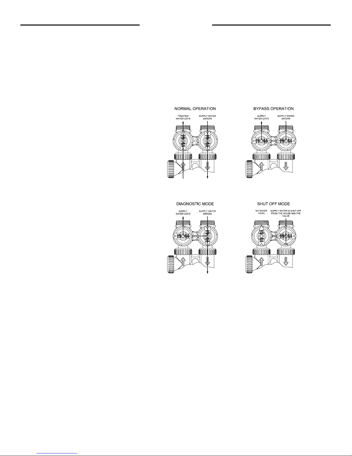
OPERATION:
1. Normal Operation Position: The inlet and outlet
handles point in the direction of ow indicated by the
engraved arrows on the control valve. Water ows
through the control valve during normal operation and
this position also allows the control valve to isolate the
media bed during the regeneration cycle. (see gure
1)
2. Bypass Position: The inlet and outlet handles
point to the center of the bypass, the control valve
is isolated from the water pressure contained in the
plumbing system. Untreated water is supplied to the
plumbing system. (see gure 2)
3. Diagnostic Position: The inlet handle points in
the direction of ow and the outlet handle points to
the center of bypass valve, system water pressure is
allowed to the control valve and the plumbing system
while not allowing water to exit from the control valve
to the plumbing. (see gure 3)
4. Shut Off Position: The inlet handle points to the
center of the bypass valve and the outlet handle
points in the direction of ow, the water is shut off
to the plumbing system. If water is available on the
outlet side of the softener it is an indication of water
bypass around the system (i.e. a plumbing connection
somewhere in the building bypasses the system).
(see gure 4)
The working parts of the bypass valve are the rotor assemblies that are contained under the bypass valve caps. Before working on the
rotors, make sure the system is depressurized. Turn the red arrow shaped handles towards the center of the bypass valve and back
several times to ensure rotor is turning freely.
The nuts and caps are designed to be unscrewed or tightened by hand. If necessary a pliers can be used to unscrew the nut or cap. Do
not use a pipe wrench to tighten or loosen nuts or caps. Do not place screwdriver in slots on caps and/or tap with a hammer. To access
the rotor, unscrew the cap and lift the cap, rotor and handle out as one unit. Twisting the unit as you pull it out will help to remove it
more easily. There are three o-rings: one under the rotor cap, one on the rotor stem and the rotor seal. Replace worn o-rings. Clean
rotor. Reinstall rotor.
When reinstalling the red arrow handles be sure that:
1. The handle pointers are lined up with the control valve body arrows, and the rotor seal o-ring and retainer on both rotors face to the
right when being viewed from the front of the control valve; or
2. Arrows point toward each other in the bypass position.
Since the handles can be pulled off, they could be accidentally reinstalled 180° from their correct orientation. To install the red arrow
handles correctly, keep the handles pointed in the same direction as the arrows engraved on the control valve body while tightening the
bypass valve caps.
gure 1 gure 2
gure 3 gure 4
PAGE 5
INSTALLATION INSTRUCTIONS
BRINE LINE FITTING CONNECTIONS
DRAIN LINE FITTING CONNECTION USING 5/8" POLY TUBE
Click to buy NOW!
P
D
F
-
X
C
H
A
N
G
E
w
w
w
.
d
o
c
u
-
t
r
a
c
k
.
c
o
m
(All electrical & plumbing should be done in accordance to all local codes)
1. Place the softener where you want to install it, making sure it is on
a clean, level and rm base.
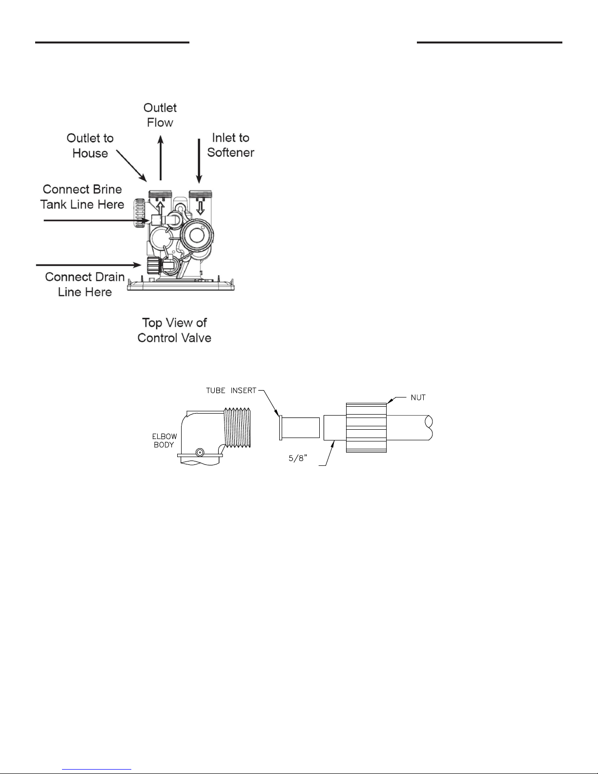
2. Do all necessary plumbing (inlet to inlet, outlet to outlet, and drain
line to drain). The control valve, ttings and/or bypass are designed to
accommodate minor plumbing misalignments but are not designed to
support the weight of a system or the plumbing.
3. When assembling the installation tting package (inlet and outlet),
connect the tting to the plumbing system rst and then attach the
nut, split ring and o-ring. Heat from soldering or solvent cements may
damage the nut, split ring or o-ring. Solder joint should be cool and
solvent cements should be set before installing the nut, split ring and
o-ring. Avoid getting primer and solvent cement on any part of the
o-rings, split rings, bypass valve or control valve.
4. A jumper ground wire should be installed between the inlet
and outlet pipe whenever the metallic continuity of a water
distribution piping system is interrupted. Install grounding strap
on metal pipes.
POLYTUBE
5. The drain connection may be made using either 5/8” polytube (see below) or a 3/4” female adapter. The polytube insert
is shipped attached to the drain line elbow’s locking clip. Press the insert into the drain line tubing (tubing not provided).
Loosen the nut of the drain line elbow. Press the 5/8” polytube with insert into the drain line elbow until it seats on the back
of the tting. Tighten the nut. If soldering, joints near the drain must be done prior to connecting the drain line ow control
tting. Leave at least 6” between the drain line control tting and solder joints when soldering pipes that are connected on
the drain line control tting. Failure to do this could cause interior damage to the drain line ow control tting. Never insert a
drain line into a drain, sewer line, or trap. Always allow an air gap between the drain line and the wastewater to prevent the
possibility of sewage being back-siphoned into the softener.
PAGE 6
BRINE LINE FITTING CONNECTIONS
Click to buy NOW!
P
D
F
-
X
C
H
A
N
G
E
w
w
w
.
d
o
c
u
-
t
r
a
c
k
.
c
o
m
INSTALLATION INSTRUCTIONS CONT’D
(All electrical & plumbing should be done in accordance to all local codes)
A
E
C
B D
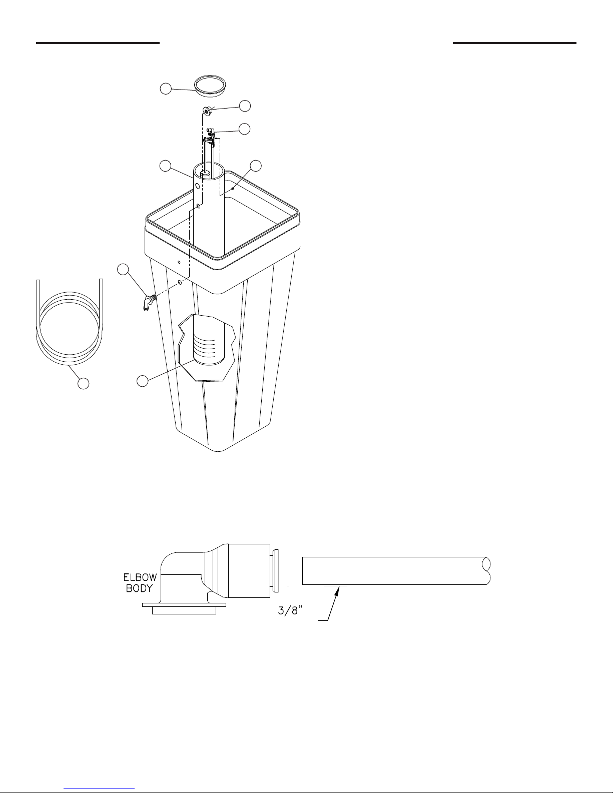
6. Assemble the brine tank. Install a brine well cap (Item A)
on the bottom of the brine well (Item B). Remove the brine
valve assembly (Item C) from the brine well by removing the
nut (Item D). Attach the brine well to the brine tank with the
two-piece overow (Items E & F) using the lower holes in
both pieces, as shown. Reinstall the brine valve assembly.
Push brine line polytube (Item G) through the upper holes in
F
the brine tank and brine well and press the polytube into the
elbow tting.
G
A
7. The brine rell ow control assembly is installed in an easy to access rell elbow located on top of the control valve. The
rell ow control assembly is attached to the control valve with a locking clip. The locking clip allows the elbow to rotate 270
degrees so the outlet can be oriented towards the brine tank.
8. Connect the brine line polytubing found with the brine tank to the brine connection on the control valve. The control valve
has a standard rell elbow to which a 3/8” exible tube can be connected, see below. Press the polytube into the brine elbow
tting. Make sure the oor is clean beneath the brine tank and that it is level and smooth.
POLYTUBE
9. A 1/2” (inside diameter, not provided) gravity drain line should be connected to the overow tting on the side of the brine
tank. This overow is in case of a malfunction in the brine shut off. If the unit is installed where water may ow in the event of
an overow and cause water damage, connect a length of exible tubing and run to a drain below the level of the overow.
(Do not connect the tubing to the drain line on the control valve. Do not run tubing above overow height at any
point.)
PAGE 7
COLD
Click to buy NOW!
P
D
F
-
X
C
H
A
N
G
E
w
w
w
.
d
o
c
u
-
t
r
a
c
k
.
c
o
m
Click to buy NOW!
P
D
F
-
X
C
H
A
N
G
E
w
w
w
.
d
o
c
u
-
t
r
a
c
k
.
c
o
m
HOT
MINIMUM 10 FEET
BETWEEN
WATER SOFTENER OUTLET
AND
WATER H EATER INLET
A SIX FOOT LENGTH OF 3/8" O.D.
BRINE LIN E POLYTUBE
SUPPLIED WITH BRINE TANK.
LOCATE WATER SOFTENER
AS CLOSE AS POSSIBLE
TO BRIN E TANK.
BYPASS PLUMBING
RECOMMENDED
IF
OPTIONAL BP2000
BYPASS VALVE
IS NOT USED.
TO
OUTSIDE
TAP
LOCATE WATER SOFTEN ER CLOSE TO A DRAIN.
AVOID OVERHEAD DRA IN LINES IF POSSIBLE TO
PREVEN T BACK P RESSURE ON BRINE INJECTOR.
IF OVER HEAD D RAIN LIN E IS USED AND EXCEEDS
5 FEET ABOVE CON NECT ION ON CONTROL VALVE
IF DRAIN LINE EXC EEDS 20 FEET IN LENGTH,
DRAIN LINE PIPE SIZ E SHOU LD BE MINIMUM 3/4".
OR
DRAIN LINE
AIR GAP
ADAPTER
WATER
HEATER
TO
DRAIN
CITY WATER
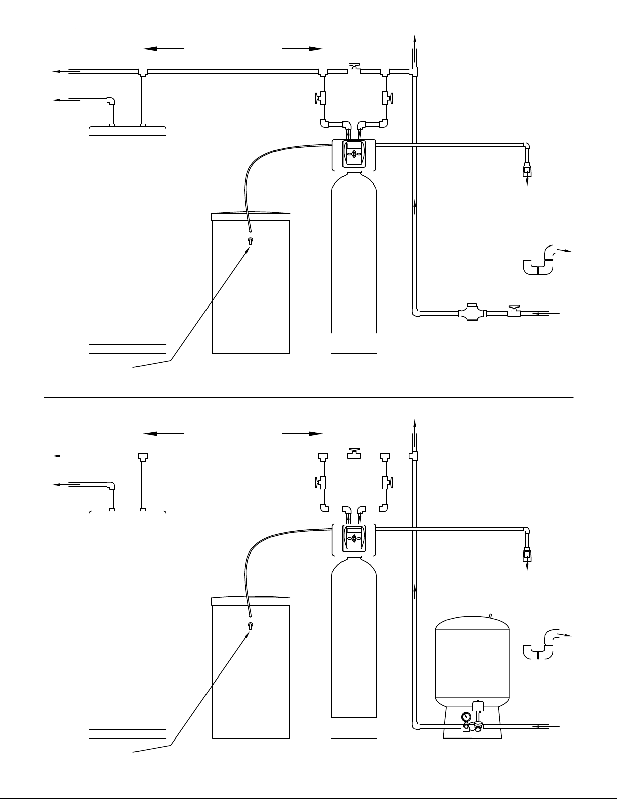
INSTALLATION
WATER
METER
BRINE TANK
OVERFLO W GRAVITY DRAIN - ON LY USED IN CASE O F MALFU NCTIO N IN TH E BRINE SHUTOFF. DO NOT CONNECT TO CONTROL VALVE DRAIN LINE.
IF UNIT IS INST ALLED WH ERE OVER FLOW C OULD CAUSE W ATER D AMAGE, CONNEC T TU BING AND RUN TO FLOOR DRAIN. DO NOT RUN TUBING ABOVE OVERFLOW HEIGHT.
MINIMUM 10 FEET
BETWEEN
WATER SOFTENER OUTLET
AND
WATER H EATER INLET
COLD
HOT
A SIX FOOT LENGTH OF 3/8" O.D.
BRINE LIN E POLYTUBE
SUPPLIED WITH BRINE TANK.
WATER S OFTENER
BYPASS PLUMBING
RECOMMENDED
IF
OPTIONAL BP2000
BYPASS VALVE
IS NOT USED.
TO
OUTSIDE
TAP
LOCATE WATER SOFTEN ER CLOSE TO A DRAIN.
AVOID OVERHEAD DRA IN LINES IF POSSIBLE TO
PREVEN T BACK P RESSURE ON BRINE INJECTOR.
IF OVER HEAD D RAIN LIN E IS USED AND EXCEEDS
5 FEET ABOVE CON NECT ION ON CONTROL VALVE
IF DRAIN LINE EXC EEDS 20 FEET IN LENGTH,
DRAIN LINE PIPE SIZ E SHOU LD BE MINIMUM 3/4".
OR
FROM
WATER MAIN
WATER
HEATER
OVERFLO W GRAVITY DRAIN - ON LY USED IN CASE O F MALFU NCTIO N IN TH E BRINE SHUTOFF. DO NOT CONNECT TO CONTROL VALVE DRAIN LINE.
IF UNIT IS INST ALLED WH ERE OVER FLOW C OULD CAUSE W ATER D AMAGE, CONNEC T TU BING AND RUN TO FLOOR DRAIN. DO NOT RUN TUBING ABOVE OVERFLOW HEIGHT.
LOCATE WATER SOFTENER
AS CLOSE AS POSSIBLE
TO BRIN E TANK.
BRINE TANK
PAGE 8
WATER S OFTENER
WELL WATER
INSTALLATION
PRESSURE
TANK
DRAIN LINE
AIR GAP
ADAPTER
TO
DRAIN
FROM
WELL PUMP
PLACING SOFTENER INTO SERVICE
Do not add salt to the brine tank yet. Do not plug the transformer into the receptacle yet. Make sure inlet and outlet valves are to their
closed positions. If using optional bypass, place in bypass position. Turn on main water supply. Open a cold water faucet. This will clear
the line of any debris (solder, pipe dope, etc.) that may be in the line. Let water run at faucet for a couple minutes, or until clear. Turn
off faucet. Manually add 1 ½ gallons of water to the brine tank. Now plug the transformer into a 120 volt receptacle (be certain the
receptacle is uninterrupted). Within 5 seconds the control display and buttons will illuminate and the time of day screen will appear.
• Press and hold the
REGEN
button for approximately 5 seconds until the motor starts.
• Wait until display reads FILL and numbers start counting down.
• Momentarily press
• Momentarily press
• Momentarily press
• Momentarily press
REGEN
again. Valve is now in the SOFTENING position.
REGEN
again. Valve is now in the BACKWASH position. (NA for model 7-LXC-50, -100)
REGEN
again. Valve is now in the REGENERANT DRAW position.
REGEN
again. Valve is now in the second BACKWASH position. (NA for model 7-LXC-50, -100)
If using optional bypass SLOWLY turn bypass valve to DIAGNOSTIC position (See gure 3 on page 5) or slowly open inlet valve to
allow water to slowly enter Softener.
When water is owing steadily to drain without the presence of air, momentarily press
REGEN
again. Display will read RINSE. Open
the outlet valve of the softener, or if using optional bypass place to NORMAL OPERATION MODE (see gure 1 on page
5). Allow control to nish the RINSE cycle. Allow the control to automatically advance to the SOFTENING position. Now
load the brine tank with salt. Solar Salt is recommended. The brine tank salt level should be checked every couple of
weeks to determine salt usage. Keeping the brine tank salt level at least 1/2 full is recommended.
SANITIZING: Use 2 oz. of 5 ¼% unscented household chlorine bleach for each cubic foot of resin. Pour bleach directly into the 4”
diameter white brine well located inside the brine tank. Press and hold the
system to complete the regeneration automatically. Check for other local and state codes which may also specify sanitation methods.
Note: The rst step of the regeneration process is to ll the brine tank with the proper amount of water. The brine tank will
only have a very slight amount of water in it after the regeneration cycles are completed.
REGEN
for 5 - 6 seconds until the motor starts running. Allow
GENERAL OPERATION
Note: As an energy saving feature, the control will automatically turn off all SOLID BLUE or SOLID GREEN display
illumination and keypad illumination after about 5 minutes of the last keypad button push. Any further keypad touch will
cause the re-illumination of the display and keypad, and re-activate keypad control.
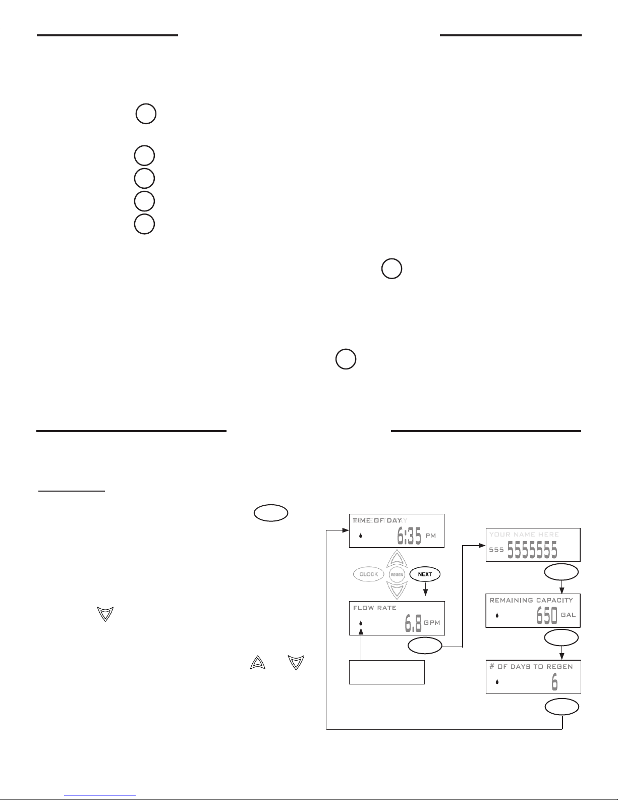
User Displays
When the system is in normal service mode, one of up to ve
available User Displays will be shown. Pressing
alternate between the following displays:
• Current time of day
• Treated water ow rate
• Service contact name and phone number (if entered)
• Remaining Capacity of treated water available
• Remaining days to regeneration (if Day Override is
programmed)
Pressing the button while in the Capacity Remaining or
Days Remaining displays will decrease the capacity remaining
in ten gallon increments or the days remaining in one day
increments.
To clear the Service Call reminder, press the and
buttons simultaneously while the number and banner text
screen is displayed.
If the system has called for a regeneration that will occur at
the preset time of regeneration, the words REGEN TODAY will
alternate with the header on the display.
Utilizing the control valve’s built-in water meter, a water drop
ashes on the display when water is being treated (i.e. water is
owing through the system).
NEXT
will
Drop will ash while water
is being treated.
Contact Screen
NEXT
NEXT
NEXT
NEXT
PAGE 9
 Loading...