

Lancaster 7-LWT-UV009, 7-LWT-UV016, 7-LWT-UV030 Installation, Operating And Service Manual
INSTALLATION, OPERATING AND SERVICE MANUAL
FOR
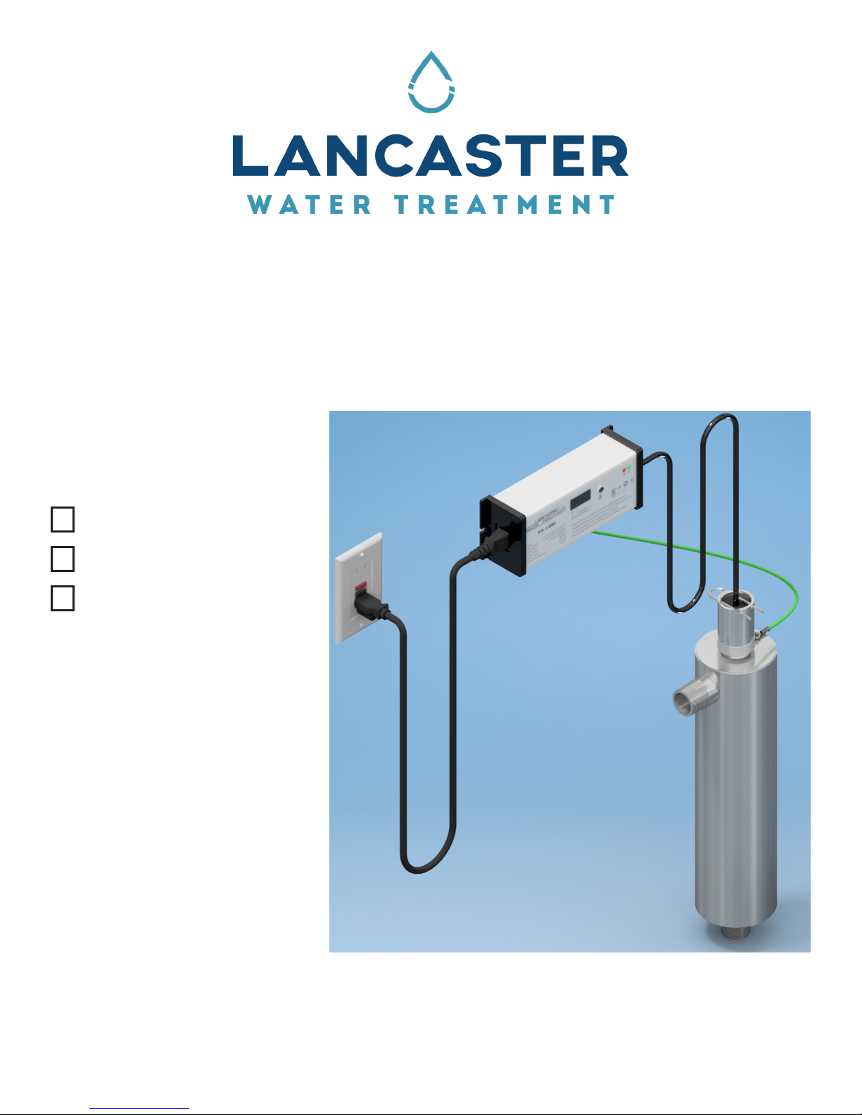
LANCASTER ULTRAVIOLET DISINFECTION SYSTEMS
PLEASE CAREFULLY READ INSTRUCTIONS BEFORE INSTALLING SYSTEM
FOLLOW ALL STATE AND LOCAL CODES AND REGULATIONS FOR PLUMBING AND ELECTRICAL.
INSTALLATION BY A CERTIFIED PLUMBER IS RECOMMENDED.
7-LWT-UV009
7-LWT-UV016
7-LWT-UV030
Congratulations on purchasing your new Lancaster Water UV Disinfection System. This unit is
designed to give you many years of trouble free service. For servicing and future inspection purposes,
please le this booklet with your important documents.
In the event that you need assistance for servicing your UV system, please rst contact the
professional contractor who installed the system.
PAGE 1

PLEASE CAREFULLY READ INSTRUCTIONS BEFORE INSTALLING SYSTEM
FOLLOW ALL STATE AND LOCAL CODES
AND REGULATIONS FOR PLUMBING AND ELECTRICAL.
INSTALLATION BY A CERTIFIED PLUMBER IS RECOMMENDED.
Safety Instructions:
WARNING - to guard against injury, basic safety precautions should be observed, including the
following:
1. READ AND FOLLOW ALL SAFETY INSTRUCTIONS.
2. CAUTION - Always disconnect power before servicing.
3. DANGER - Warning: the UV light given off by this unit can cause serious burns to
unprotected eyes and skin. Never look directly at an illuminated UV lamp. When performing
any work on the UV disinfection system always unplug the unit rst. Never operate the UV
system while the UV lamp is outside of the UV chamber.
4. DANGER - To avoid possible electric shock, special care should be taken since water is present
near electrical equipment. Unless a situation is encountered that is explicitly addressed by the
provided maintenance and troubleshooting sections, do not attempt repairs yourself, refer to a
certied plumber/technician.
5. Carefully examine the disinfection system after installation. It should not be plugged in if there is
water on parts not intended to be wet such as the ballast or lamp connector.
6. Do not operate the disinfection system if it has a damaged cord or plug, if it is malfunctioning or if
it has been dropped or damaged in any manner.
7. Always disconnect water ow and unplug the disinfection system before performing any cleaning
or maintenance activities. Never yank the cord to remove from an outlet; grasp the wall plug and
pull to disconnect.
8. Do not use this disinfection system for other than intended use (potable water application).The use
of attachments not recommended or sold by the manufacturer/distributor may cause an unsafe
condition.
9. Intended for indoor use only. Do not install this disinfection system where it will be exposed to the
weather or to temperatures below freezing. Do not store this disinfection system where it will be
exposed to temperatures below freezing unless all water has been drained from it and the water
supply has been disconnected.
10. Read and observe all the important notices and warnings on the water disinfection system.
11. If an extension cord is necessary, a cord with a proper rating should be used. A cord rated for
less Amperes or Watts than the disinfection system rating may overheat. Care should be taken to
arrange the cord so that it will not be tripped over or pulled.
12. A dedicated circuit breaker must not exceed the electronic ballast power cord current rating (10A
for 125V, 18AWG x 3C, SVT or SJT cord type).
13. To avoid creating an electric shock hazard, never attempt to operate the disinfection system
unless it has rst been properly grounded.
14. To prevent an electric shock, do not plug the disinfection system into any socket that has not been
equipped with a Ground Fault Circuit Interrupter (GFCI).
15. SAVE THESE INSTRUCTIONS.
Note: The UV lamp inside the disinfection system is rated at an effective life of approximately 9000
hours. To ensure continuous protection, replace the UV lamp annually.
PAGE 2
PRODUCT OVERVIEW:
Click to buy NOW!
P
D
F
-
X
C
H
A
N
G
E
w
w
w
.
d
o
c
u
-
t
r
a
c
k
.
c
o
m
Click to buy NOW!
P
D
F
-
X
C
H
A
N
G
E
w
w
w
.
d
o
c
u
-
t
r
a
c
k
.
c
o
m
Please read this manual thoroughly for a detailed explanation of the system.
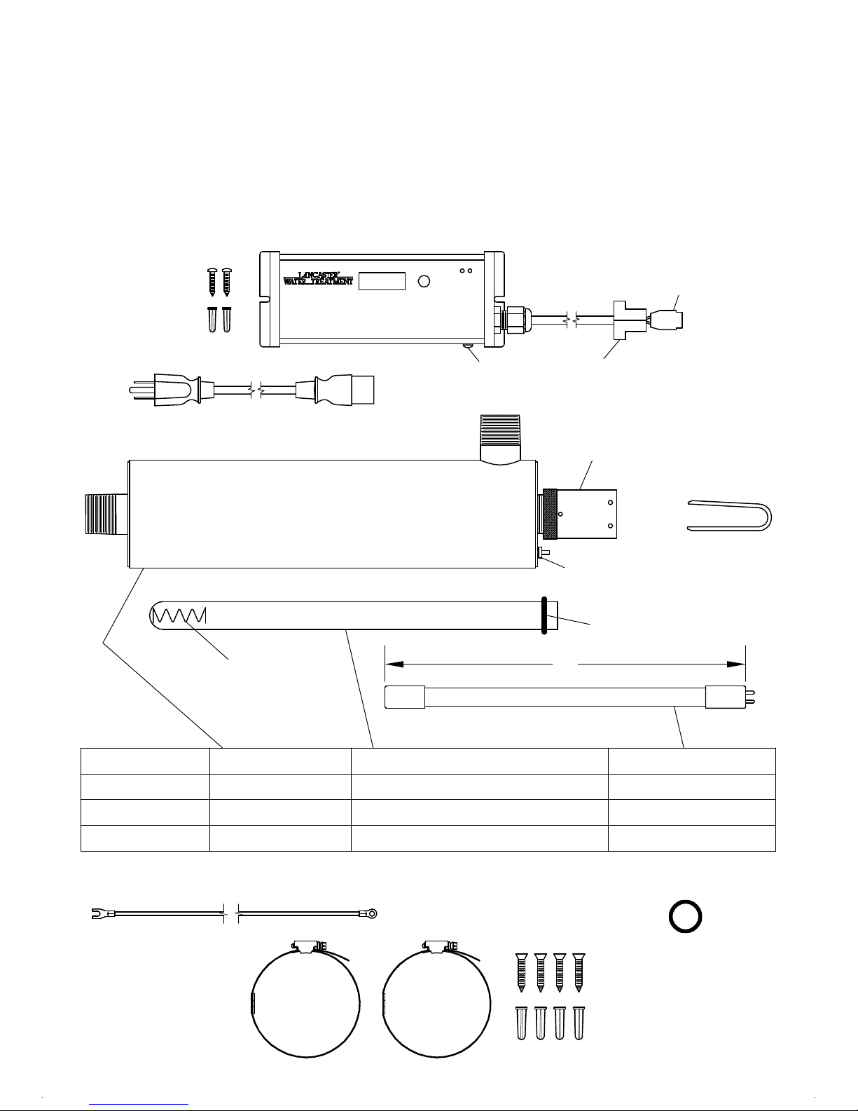
The following is a description of the components that make up the system.
Ensure that the following components accompany the system .
To ensure system performance, all replacement components should be purchased
from an authorized dealer or directly from Lancaster Water Treatment.
The use of components purchased from other sources will void the warranty and
could cause the system to operate at a lower performance than intended.
7-UVC Electronic Ballast
Qty (2): 21S-UV
Electronic Ballast
Mounting Screw
Qty (2): 21A-UV
Electronic Ballast
Mounting Anchor
2'-8" Lamp Cordset with Lamp Connector attached
Ground Screw
attached
15-UV Bushing
Electronic Ballast 5 ft. Power Cordset
Aluminum Gland Nut
CAUTION: HAND TIGHTEN ONLY!
17-UV Ground Nut
CAUTION: keep quartz sleeve free of finger prints and dirt!
18-UV
A
Lamp Compression
Spring
CAUTION: handle lamp by the ceramic end caps;
keep lamp quartz free of finger prints and dirt!
Model SS UV Chamber Domed Quartz Sleeve (length)
14-UV
16-UV U-Clip
OR-212 O-Ring
Four
pins
UV Lamp (A)
7-LWT-UV009
7-LWT-UV016
7-LWT-UV030
100-UV
200-UV
300-UV
19-UV
3 ft. Ground Wire
Qty (2): 20-UV
UV Chamber
Mounting Bracket
7-Q6 (13-1/8")
7-Q10 (21-3/8")
7-Q20 (34-3/4")
PAGE 3
7-L6 (11-13/16")
7-L10 (20-1/16")
7-L20 (33-3/16")
OR-212 O-Ring
Qty (4): 20S-UV
Mounting Bracket Screw
Qty (4): 20A-UV
Mounting Bracket Anchor
(spare)
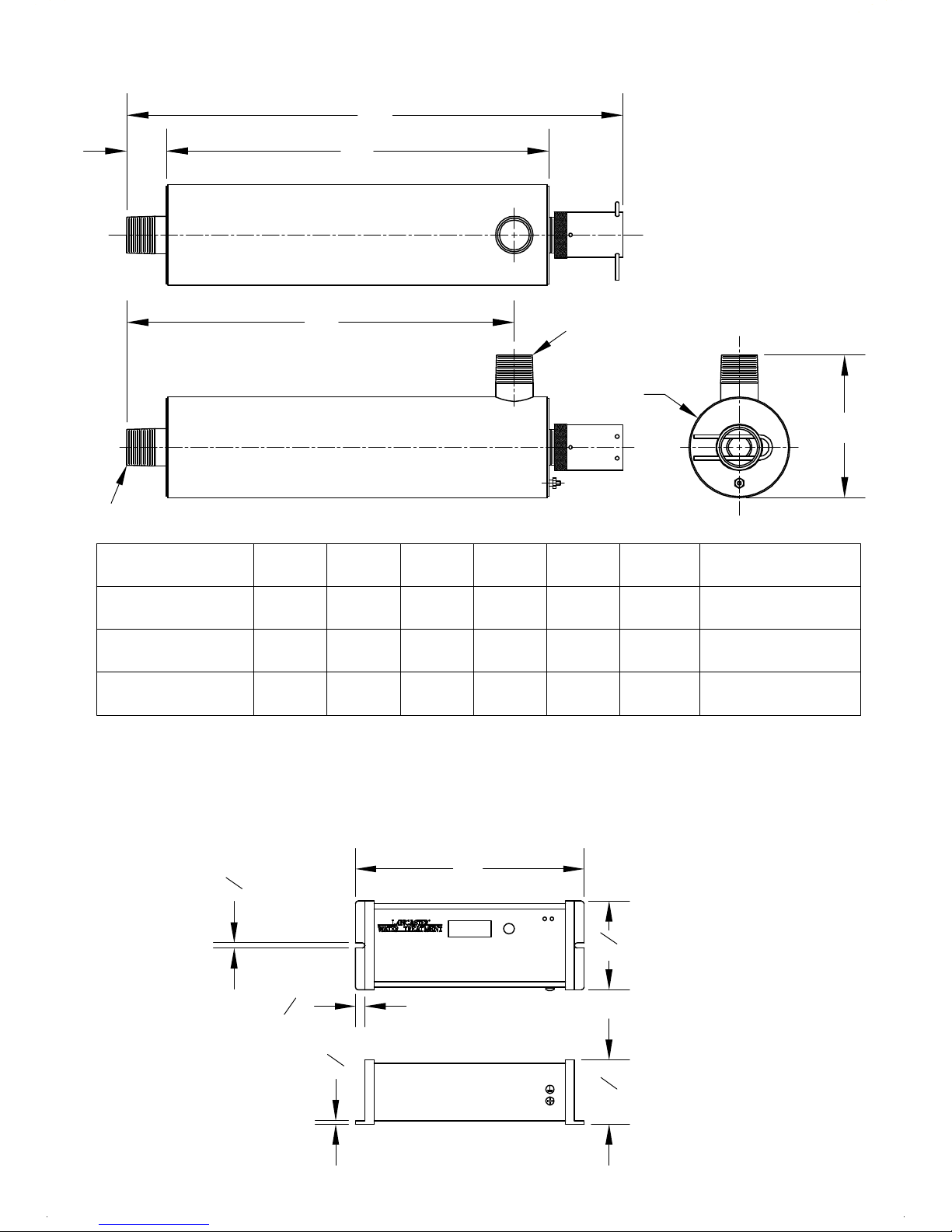
DIMENSIONS:
Click to buy NOW!
P
D
F
-
X
C
H
A
N
G
E
w
w
w
.
d
o
c
u
-
t
r
a
c
k
.
c
o
m
Click to buy NOW!
P
D
F
-
X
C
H
A
N
G
E
w
w
w
.
d
o
c
u
-
t
r
a
c
k
.
c
o
m
A
INLET
C
MODEL
D
B
OUTLET
F
E
INLET/OUTLETA B C D E F (DIA.)
7-LWT-UV009
7-LWT-UV016
7-LWT-UV030
PART NUMBER 7-UVC ELECTRONIC BALLAST/CONTROLLER
1.0 MNPT
1.0 MNPT
1.5 MNPT
21-11/16 21-13/161-3/8
517-3/8 13-3/8 1-3/8 13-9/16
525-5/8
5-1/42-1/839-3/4 35-1/16 35-9/16
3-1/2
3-1/2
3-1/2
GENERAL NOTES FOR ESTIMATING ONLY.
ALL DIMENSIONS ARE IN INCHES.
16
3
8
8
1
3
5
16
8
1
4
1
2
PAGE 4
 Loading...