

Lancaster 7-LMC56-75B, 7-LM56-75B, 7-LM56-100B, 7-LM56-150B, 7-LM56-200B Installation, Operating And Service Manual
INSTALLATION,
Click to buy NOW!
P
D
F
-
X
C
H
A
N
G
E
w
w
w
.
d
o
c
u
-
t
r
a
c
k
.
c
o
m
OPERATING AND
SERVICE MANUAL
ECONO-mist WATER SOFTENER
Demand Regeneration
•• • • • • • • •
• • • • • •• • • •• • •• •
7-LMC56-75B
7-LM56-75B
7-LM56-100B
7-LM56-150B
7-LM56-200B
Congratulations on purchasing your new Lancaster Water Filter. This unit is designed to give you
many years of trouble free service. For servicing and future inspection purposes, please le this
booklet with your important documents.
In the event that you need assistance for servicing your water softener, please rst contact the
professional contractor who installed the system.
PAGE 1
INSTALLATION
Click to buy NOW!
P
D
F
-
X
C
H
A
N
G
E
w
w
w
.
d
o
c
u
-
t
r
a
c
k
.
c
o
m
Place softener in desired location close to water supply inlet, after pressure tank, and near a source for waste water,
(utility sink, oor drain or sewer line). Keep far enough away from walls and other obstructions to allow enough room for
servicing the unit. All sillcocks and similar xtures that will use untreated water must have their pipes connected to the
hard water side of the softener. A bypass valve (optional accessory) should be installed so that water will be available if it
should be necessary to shut off the pressure in order to service the softener.
The cabinet tank or mineral tank must be reasonably level and solidly in place. Prior to beginning work to the system,
make sure that water pressure is shut off at the incoming water supply and that several water spigots are open to prove
sufcient venting for drainage of that system.
Arrows are molded into the control valve to show the direction of the ow.
OPTIONAL BYPASS VALVE: The bypass valve easily connects to the control valve body using screws and adapter
clips. Install with red handle in the upward position. Press slip end of bypass valve onto in/out connections of valve. Take
care not to crimp o-rings. Place into BYPASS POSITION. Do not use Vaseline or other unacceptable lubricants on o-
rings. A silicone lubricant may be used on black o-rings.
DRAIN LINE: Drain line tting accommodates 1/2” I.D. exible poly tube.
It is simplest to run the drain line into a sump pump pit or washing machine drain if possible. If this is not practical, a tting
with a trap must be installed in a sewer line. Place the trap as close to the vent as possible to prevent siphoning of the
trap when large amounts of waste water go through the sewer line. DO NOT pipe the drain line solidly into the waste line,
as this is prohibited by most plumbing codes. The drain line should enter the trap from above so the water will not back up
in the drain line if sewer should become plugged up and the trap overow. The trap should have a short pipe extending
from it to prevent splashing when water runs into the trap from drain line.
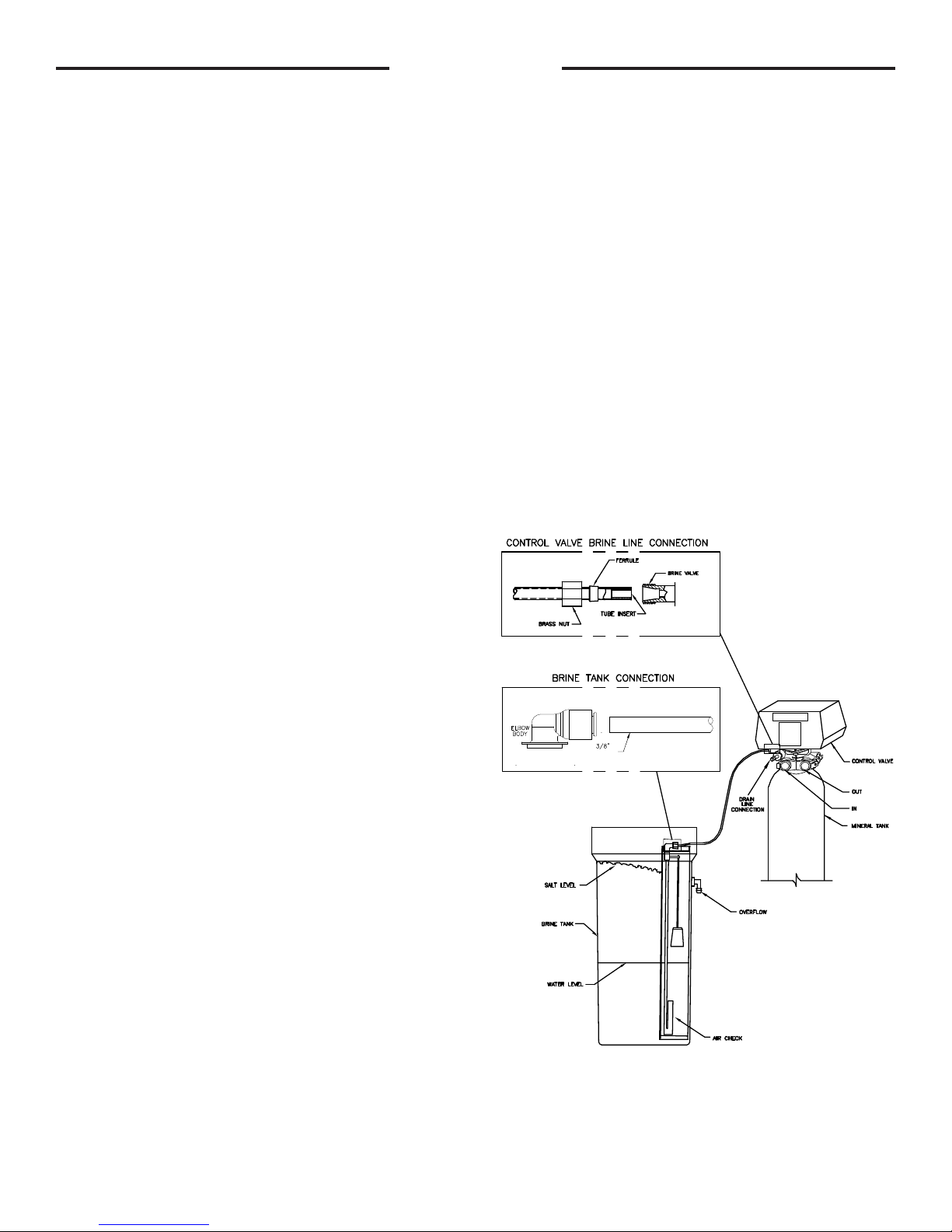
BRINE LINE CONNECTIONS: 3/8” poly tube is
shipped inside of the brine tank along with a ttings package.
MAKE CONNECTION TO BRINE TANK: Press the polytube
into the brine elbow tting.
MAKE CONNECTION TO CONTROL VALVE: Slide brass
nut onto 3/8” poly tube. Slide ferrule onto poly tube as shown
in diagram. Install tube insert. Press fully into brine valve t-
ting. Tighten brass nut.
BRINE TANK OVERFLOW PRECAUTION: Attach
a 1/2” poly tube (not provided) to the barbed tting on the
outside of the tank. This poly tube should be piped to drain to
allow brine to discharge to drain in the event of an overow
condition.
SANITIZING: Use 2 oz. of 5¼% household chlorine
bleach for each cubic foot of resin. Pour bleach directly into
the brine well of the softener. Manually index the softener to
the REGEN position. Allow system to complete the regeneration
automatically. Check for other local and state codes which
may also specify sanitation methods. This is to be done after
placing unit into service. (see next page.)
POLYTUBE
PAGE 2
PLACING UNIT INTO SERVICE:
1. Manually index the softener control into the backwash position. Slowly open bypass valve and allow water to ow into
the resin tank. When the water ows steadily to drain without the presence of air, index control to service position.
NOTE: the various regeneration positions may be dialed manually by turning the knob on the front of the control
clockwise until the indicator shows that the softener is in the desired position. VARIOUS REGENERATION
POSITIONS ARE:
1. IN SERV. 3. RINSE 5. BRINE + RINSE 7. SETTLE RINSE
2. REGEN. 4. BACK WASH 6. RAPID RINSE 8. BRINE REFILL
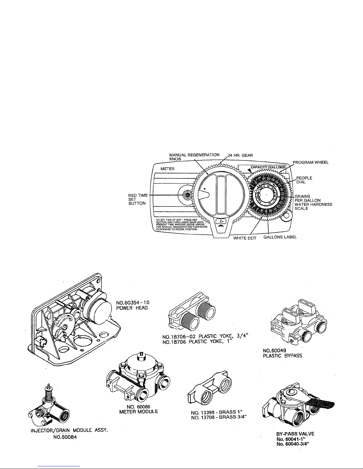
2. Set water usage program wheel using the following procedure:
Typical Residential Application: To program the unit, set the correct time of day, set the hardness of your water and
the softener will automatically monitor your usage, regenerating only when necessary. To set time of day press red
time set button and turn 24 hour gear until present time of day is opposite “time of day.” Set program wheel by lifting
the “people” dial and rotating it so that the number of people in the household is aligned with the “grains per gallon”
water hardness scale. Release the dial and check for rm engagement at setting. (This method will provide reserve
capacity based on 50 gallons per person.)
3. Rotate the program wheel
counter clockwise until it stops
at regeneration position.
4. Add 1-1/2 gallons of water to the
brine tank.
5. Plug in the electrical cord and
look in the sight hole in the back
of the motor to see that it is
running.
6. Manually advance the control to
the beginning of the brine rell
position and allow the control to
return to the service
position automatically.
7. Fill the brine tank with salt. Maintain salt level above water level. We recommend Solar Salt.
8. Make sure bypass valve(s) is in the service position.
PAGE 3
 Loading...