

Lancaster PACESETTER 7-PEL-75B, PACESETTER 7-PEL-150B, PACESETTER 7-PEL-100B, 7-LECR-75, 7-LECR-100 Installation, Operating And Service Manual
...
INSTALLATION, OPERATING
AND SERVICE MANUAL
PACESETTER
ELECTRONIC WATER SOFTENER
WITH THE PEL VALVE
7-PEL-75B
7-PEL-100B
7-PEL-150B
Congratulations on purchasing your new Lancaster Water Softener. This unit is designed to give
you many years of trouble free service. When installed in accordance with the following instructions
and if given reasonable care, clear-soft water will be the result. For servicing and future inspection
purposes, please le this booklet with your important documents.
PAGE 1

OPERATING PARAMETERS
Minimum / Maximum Operating Pressures 20 psi (138 kPa) - 125 psi (862 kPa)
Minimum / Maximum Operating Temperatures 40°F (4°C) - 110°F (43°C)
Supply Voltage/ Frequency 120V AC/ 60 Hz Other Options Available
Power Consumption 9.5 W
Output Voltage 12V AC
Output Current 500 mA
GENERAL WARNINGS
The control valve, ttings and/or bypass are designed to accommodate minor plumbing misalignments but are not designed
to support the weight of a system or the plumbing.
Do not use Vaseline, oils, other hydrocarbon lubrications or spray silicone anywhere. A silicone lubricant may be used on
black o-rings but is not necessary. Avoid any type of lubricants, including silicone, on red or clear lip seals.
The nuts and caps are designed to be unscrewed or tightened by hand or with the special plastic wrench (P/N V3193). If
necessary, pliers can be used to unscrew the nut or cap. Do not use a pipe wrench to tighten or loosen nuts or caps. Do not
place screwdriver in slots on caps and/or tap with hammer.
Do not use pipe dope or any other sealant on threads. Teon tape must be used on the threads of the 1” NPT elbow or the
1/4” NPT connection and on the threads for the drain line connection. Teon tape is not necessary on the nut connection or
caps because of o-ring seals.
After completing any valve maintenance involving the drive assembly and pistons, press and hold NEXT and REGEN
button for three seconds or unplug power source jack from printed circuit board (black wire) and plug back in. This resets
the electronics and establishes the service piston position. The display should ash all wording , then ash software version
(e.g. 220.1) and then reset the valve to the service position.
All plumbing should be done in accordance with local plumbing codes. The pipe size of the drain line should be a minimum
of 1/2”. Backwash ow rates in excess of 7 gpm or length in excess of 20’ require 3/4” drain line.
Solder joints near the drain must be done prior to connecting the drain line ow control tting. Leave at least 6” between the
drain line control tting and solder joints when soldering pipes that are connected on the drain line control tting. Failure to
do this could cause interior damage to the drain line ow control tting.
When assembling the installation tting package(P/N V3007) to the inlet and outlet (see Page 7), connect the tting to the
plumbing system rst and then attach the nut, split ring and o-ring. Heat from soldering or solvent cements may damage the
nut, split ring or o-ring. Solder joints should be cool and solvent cements should be set before installing the nut, split ring and
o-ring. Avoid getting primer and solvent cement on any part of the o-rings, split rings, bypass valve or control valve.
Plug into an electrical outlet. NOTE: All electrical connections must be connected according to local codes. (Be certain the
outlet is uninterrupted.) Install grounding strap on metal pipes.
Place softener in desired location close to water supply inlet, after pressure tank, and near a source for waste water, (utility
sink, oor drain or sewer line). A 115/120V, 60 Hz uninterrupted outlet is required. Keep softener far enough away from walls
and other obstructions to allow enough room for servicing the unit. All sillcocks and similar xtures that will use untreated
water must have their pipes connected to the hard water side of the softener. A bypass valve (optional accessory) should
be installed so that water will be available if it should be necessary to shut off the pressure in order to service the softener.
The cabinet tank or mineral tank must be reasonably level and solidly in place. Prior to beginning work to the system, make
sure that water pressure is shut off at the incoming water supply and that several water spigots are open to provide sufcient
venting for drainage of that system.
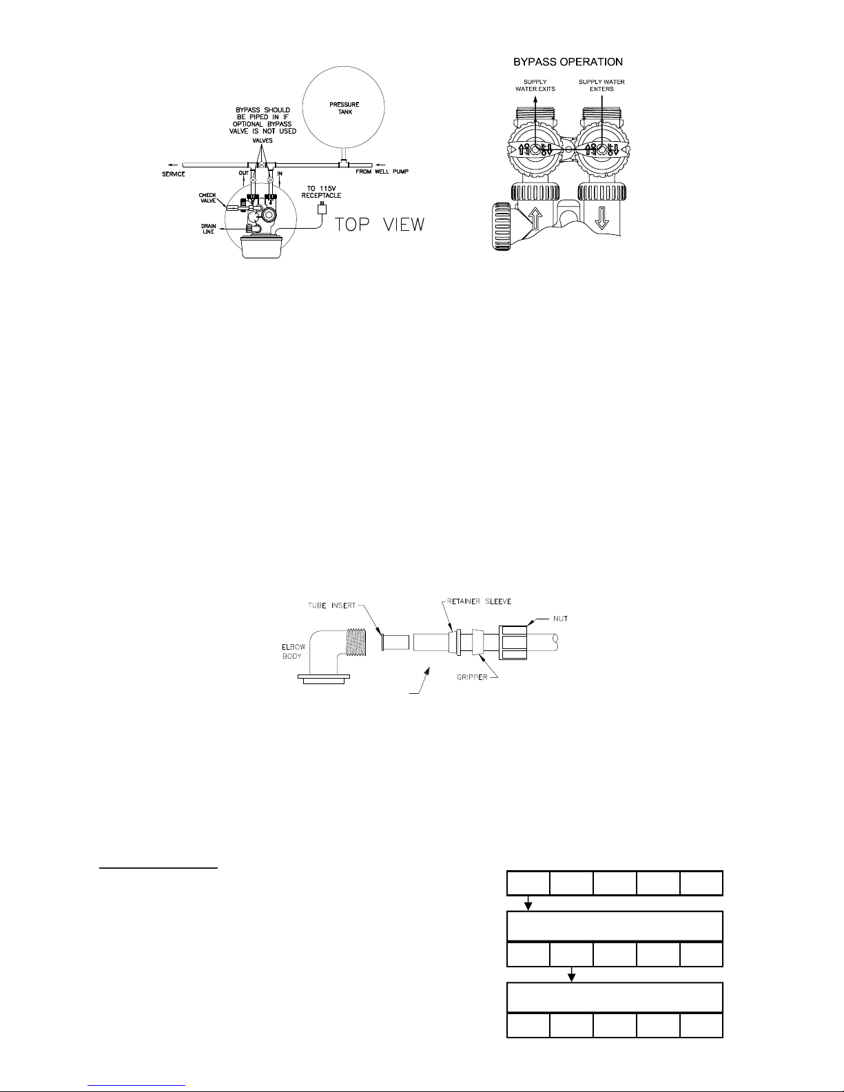
Arrows are molded into the control valve to show the direction of the ow.
OPTIONAL BYPASS VALVE: The bypass valve easily connects to the control valve body using nuts that only require hand
tightening. Install with red knobs in the upward position. Press end of bypass valve with o-rings into valve. Hand tighten nuts.
Place into BYPASS OPERATION (gure 1 page 3).
Avoid getting primer and solvent cement on any part of the o-rings or split rings, bypass valve or control valve. DO NOT use
pipe dope or any other sealant on threads. Teon tape is not necessary on the caps because of o-ring seals. Do not use
Vaseline or other unacceptable lubricants on o-rings. A silicone lubricant may be used on black o-rings.
DRAIN LINE: The 3/4” drain line elbow accommodates 5/8” poly tube or 3/4” NPT drain line connections. The nut and poly
tube insert for the 3/4” drain line elbow is designed for use with exible poly tube only. The drain line elbow can be rotated
so the outlet can be oriented toward the nearest drain.
INSTALLATION
PAGE 2
Click to buy NOW!
P
D
F
-
X
C
H
A
N
G
E
w
w
w
.
d
o
c
u
-
t
r
a
c
k
.
c
o
m
FIGURE 1
FIGURE 1
TO INSTALL 5/8” POLY TUBE DRAIN LINE: The poly tube insert is shipped attached to the drain line elbow’s locking clip.
Press the insert into the drain line (5/8” poly tube not included). Loosen nut of the drain line elbow. Press 5/8” poly tube with
insert into the drain line elbow until it seats on the back of the tting. Tighten nut.
It is simplest to run the drain line into a sump pump pit or washing machine drain if possible. If this is not practical, a tting
with a trap must be installed in a sewer line. Place the trap as close to the vent as possible to prevent siphoning of the trap
when large amounts of waste water go through the sewer line. DO NOT pipe the drain line solidly into the waste line, as this
is prohibited by most plumbing codes. The drain line should enter the trap from above so the water will not back up in the
drain line if sewer should become plugged up and the trap overow. The trap should have a short pipe extending from it to
prevent splashing when water runs into the trap from drain line.
BRINE LINE CONNECTIONS: 3/8” poly tube is shipped within the instruction/warranty card packet afxed to the control
valve. One poly tube insert is shipped on the brine line elbow’s locking clip, the second is taped to the cap of the brine well.
Remove the locking clip by pulling straight out. Remove the white poly tube insert from the locking clip, and replace the
locking clip on the brine line elbow of the control valve.
Press the poly tube insert into the provided 3/8” poly tube. Press the poly tube and insert into the nut until it is fully seated
into the tting. Do not use pipe dope or any other sealant on threads. Teon tape is not needed on the threads. Tighten nut
securely to create a pressure tight connection. Pliers or crescent wrench may be used. The nut, gripper and retainer sleeve
is a three piece assembly that can come apart if removed from the elbow body. Parts must be reassembled exactly as
shown to function properly. If the nut is completely removed from the body, slip the nut, plastic gripper and retainer sleeve
on to the tube then tighten on to the tting.
Install the second poly tube insert into the end of the 3/8” poly tube and repeat instructions above to install into the brine
tank’s brine line tting.
BRINE TANK OVERFLOW PRECAUTION: Attach a 1/2” poly tube (not provided) to the barbed tting on the outside of the
tank. This poly tube should be piped to drain to allow brine to discharge to drain in the event of an overow condition.
PROGRAMMING THE CONTROL VALVE: Note: A quick-reference card is stored inside the front cover of the control valve.
To access this card, slightly pull tabs on side of cover outward and pull cover forward. Plug the electrical cord into a 115
Volt receptacle. DO NOT plug into an outlet controlled by a wall switch or pull chain that could inadvertently be turned off.
Wait a couple of seconds for control valve to “home” itself. Panel should display “TIME” and the time of day will be ashing.
SET TIME OF DAY
STEP 1: Press SET CLOCK.
STEP 2: Set current hour of the day by pressing ▲
or ▼ buttons. AM/ PM toggles after 12.
STEP 3: Press NEXT. Set current minutes by
pressing ▲ or ▼ buttons.
STEP 4: Press NEXT to exit SET CLOCK.
3/8”
POLY TUBE
PAGE 3
SET
CLOCK
SET TIME
NEXT
▲ ▼
STEP 1
REGEN
STEP 2
6:35
SET
CLOCK
SET TIME
NEXT
▲ ▼
REGEN
STEP 3
6:35
SET
CLOCK
NEXT
▲ ▼
REGEN
PM
PM
 Loading...