


PILOT’S OPERATING
Legacy
HANDBOOK
and
AIRPLANE FLIGHT MANUAL
for the
LEGACY
Mfgr’s Serial No. ___________________________
Registration No. ___________________________
Owners will need to develop a Pilot’s Operating Handbook as part
of the aircraft airworthiness process, and are encouraged to modify
this document to help in that process.

Legacy
Published by
Lancair International Inc.
Redmond, Oregon 97756
Authorized Dealer
Neico Aviation Inc.
2244 Airport Way
Redmond, Oregon 97756

Legacy
PILOT’S OPERATING HANDBOOK
and
AIRPLANE FLIGHT MANUAL
February 2008
Log of Revisions
PAGES DESCRIPTION
iiiFebruary 2008

Legacy
vFebruary 2008
Legacy
INTRODUCTION
This Lancair International Pilot’s Operating Handbook and Airplane Flight
Manual is in the format and contains most data recommended in the GAMA
(General Aviation Manufacturers Association) Handbook Specification Number
1. Use of this specification provides the pilot the same type data in the same
place in all of the handbooks.
For example, attention is called to Section X, SAFETY INFORMATION.
We feel it is very important to have this information in a condensed and readily
available location and format for the pilots immediate use when needed.
This SAFETY INFORMATION should be read and studied by all operators of the Lancair Legacy aircraft and will provide a periodic review of good
piloting techniques for this aircraft. This manual will not replace safe flight
instruction or good piloting techniques.
NOTE
Owner modifications to your Lancair may alter
the applicability of this handbook which meets
the GAMA specification #1 for pilots operating
handbooks.
WARNING
Use only genuine Lancair approved parts obtained
from authorized Lancair dealers when repairing and
maintaining your Lancair Legacy.
Lancair parts are produced and inspected under controlled procedures to
ensure airworthiness commensurate with use in the Lancair. Other than these
approved parts, while appearing suitable, may not have been fabricated under
adequately controlled conditions and may be unsuitable and dangerous when
used in our Lancair.
Lancair and its dealers expressly disclaim any responsibility for malfunctions, failures, damage or injury caused by the use of non-approved parts.
iv
February 2008

Legacy
CONTENTS
SECTION I . . . . . . . . . . . . . . . . . . . . . . . . . . . . . . . . . . . . . . . . . . GENERAL
SECTION II . . . . . . . . . . . . . . . . . . . . . . . . . . . . . . . . . . . . . . LIMITATIONS
SECTION III . . . . . . . . . . . . . . . . . . . . . . . . .EMERGENCY PROCEDURES
SECTION IV . . . . . . . . . . . . . . . . . . . . . . . . . . . . NORMAL PROCEDURES
SECTION V . . . . . . . . . . . . . . . . . . . . . . . . . . . . . . . . . . . .PERFORMANCE
SECTION VI . . . . . . . . . . . WEIGHT AND BALANCE/EQUIPMENT LIST
SECTION VII . . . . . . . . . . . . . . . . . . . . . . . . . . . SYSTEM DESCRIPTIONS
SECTION VIII . . . . . . . . . HANDLING, SERVICING & MAINTENANCE
SECTION IX . . . . . . . . . . . . . . . . . . . . . . . . . . . . . . . . . . . . SUPPLEMENTS
HANDBOOK TABLE OF
SECTION X . . . . . . . . . . . . . . . . . . . . . . . . . . . . .SAFETY INFORMATION
vFebruary 2008

Legacy
I-1February 2008
Legacy
GENERAL
Legacy
IMPORTANT NOTICE . . . . . . . . . . . . . . . . . . . . . . . . . . . . . . . . . . . . . . I-3
USE OF THIS HANDBOOK . . . . . . . . . . . . . . . . . . . . . . . . . . . . . . . . . . . I-4
REVISING THIS HANDBOOK . . . . . . . . . . . . . . . . . . . . . . . . . . . . . . . . I-5
ABSOLUTE MINIMUM TURNING RADIUS . . . . . . . . . . . . . . . . . . . . . I-6
LEGACY THREE VIEW . . . . . . . . . . . . . . . . . . . . . . . . . . . . . . . . . . . . . . I-7
DESCRIPTIVE DATA . . . . . . . . . . . . . . . . . . . . . . . . . . . . . . . . . . . . . . . . I-8
ENGINES . . . . . . . . . . . . . . . . . . . . . . . . . . . . . . . . . . . . . . . . . . . . . . . I-8
PROPELLERS . . . . . . . . . . . . . . . . . . . . . . . . . . . . . . . . . . . . . . . . . . . . I-8
FUELS . . . . . . . . . . . . . . . . . . . . . . . . . . . . . . . . . . . . . . . . . . . . . . . . I-8
OIL CAPACITIES . . . . . . . . . . . . . . . . . . . . . . . . . . . . . . . . . . . . . . . . . I-9
CABIN AND ENTRY DIMENSIONS . . . . . . . . . . . . . . . . . . . . . . . . . . . . . . I-9
BAGGAGE . . . . . . . . . . . . . . . . . . . . . . . . . . . . . . . . . . . . . . . . . . . . . . I-9
SPECIFIC LOADINGS (MAX TAKE-OFF WT) . . . . . . . . . . . . . . . . . . . . . . I-9
GENERAL AIRSPEED TERMINOLOGY AND SYMBOLS . . . . . . . . . I-10
METEOROLOGICAL TERMINOLOGY . . . . . . . . . . . . . . . . . . . . . . . . I-11
POWER TERMINOLOGY . . . . . . . . . . . . . . . . . . . . . . . . . . . . . . . . . . . . I-11
ENGINE CONTROLS/INSTRUMENTS . . . . . . . . . . . . . . . . . . . . . . . . . I-11
AIRPLANE PERFORMANCE &
FLIGHT PLANNING TERMINOLOGY . . . . . . . . . . . . . . . . . . . . I-12
WEIGHT AND BALANCE TERMINOLOGY . . . . . . . . . . . . . . . . . . . . I-12
NOTES: . . . . . . . . . . . . . . . . . . . . . . . . . . . . . . . . . . . . . . . . . . . . . . . . . . . I-14
S
ECTION
T
ABLE OF CONTENTS
1
I-1February 2008
Legacy
I-3February 2008
Legacy
Intentionally Left Blank
I-2
February 2008

Legacy
THANK YOU...
You have obtained what we feel is the latest state-of-the-art in a high performance
general aviation aircraft. Its performance is spectacular and its life almost beyond
measure given reasonable care. A team of outstanding craftsmen has been assembled to design and produce quality aircraft components which can serve you
well for years to come. We encourage you to become familiar with this handbook
as well as the FARs that are applicable to your operation. The combination will
provide you with safe and sound knowledge for operation of your personally
manufactured Lancair.
IMPORTANT NOTICE
This handbook should be read carefully by the owner or operator(s) of your Lancair
in order to become familiar with its operation and to obtain all it has to offer in terms
of both speed and reliability. Herein are suggestions and recommendations to help
you obtain safe performance without sacrificing economy. You are encouraged to
operate your machine in accordance with and within the limits identified in this
Pilot’s Operating Handbook and Airplane Flight Manual as well as any placards
located in the airplane.
Again, another reminder- the operator should also be familiar with the Federal Aviation Regulations as applicable to the operation and maintenance of experimental
aircraft and FAR Part 91 General Operating and Flight Rules. The aircraft should
be operated and maintained in accordance with any FAA Airworthiness Directives
which may be issued against it. It is also prudent and mandatory to operate within
any established limits or Service Bulletins.
The FARs place the responsibility for the maintenance of this airplane on the owner
and the operator who must ensure that all maintenance is accomplished by the
owner or qualified mechanics in conformity with all airworthiness requirements
established for this airplane.
All limits, procedures, safety practices, time limits, servicing, and maintenance
requirements contained in this handbook are considered necessary for the con-
tinued airworthiness of this airplane, in a condition equal to that of its original
manufacture.
Authorized Service Facilities can provide recommended service, repair, or operating procedures issued by both the FAA and Lancair International, Inc. to obtain the
maximum prudent usefulness and safety from your Lancair Legacy.
I-3February 2008

Legacy
I-5February 2008
Legacy
USE OF THIS HANDBOOK
The Pilot’s Operating Handbook is designed so that necessary documents may be
maintained for the safe and efficient operation of your 2-place Lancair. Its loose leaf
form allows easy maintenance for updates and revisions, and is also a convenient
size for storage and use within the cockpit.
The handbook is in ten basic sections in accordance with the GAMA Specification
No.1, Issued 15 February 1975, Revised 1 September 1984, Revision #1.
NOTE
Except as noted, all airspeeds quoted in this
handbook are Indicated Airspeeds (IAS) in Knots,
and assume zero instrument error .
In an effort to provide as complete coverage as possible of the Lancair Legacy, some
optional equipment has been included in the scope of this handbook. However,
due to the variety of airplane configurations available, some equipment described
and depicted herein may not be included on your specific airplane.
The following information may be provided to the holder of this manual automatically:
1. Original issues and revisions of Service Bulletins
2. Original issues and revisions of Lancair Airplane Flight Manual Supplements
3. Reissues and revisions of Lancair Airplane Flight Manuals, Flight
Handbooks, Owner’s Manuals, Pilots Operating Manuals, and Pilots
Operating Handbooks
I-4
February 2008

Legacy
NOTICE
Lancair International Incorporated expressly
reserves the right to supersede, cancel, and/or
declare obsolete, without prior notice, any part, part
The owner/operator should frequently refer to all supplements, whether STCs
(Supplemental Type Certificate) or Lancair Supplements direct from Lancair or
its dealers, for appropriate placards, limitations, normal, emergency and other
operational procedures for proper operation of their Lancair with any optional
equipment installed.
REVISING THIS HANDBOOK
Immediately following the title page is the “Log of Revisions” page (s). The Log
of Revision pages are used for maintaining a listing of all effective pages in the
handbook (except the SUPPLEMENTS section), and as a record of revisions to
these pages. In the lower right corner of the outlined portion of the Log is a box
containing a capital letter which denotes the issue or reissue of the handbook. This
letter may be suffixed by a number which indicates the numerical revision. When
a revision to any information in the handbook is made, a new Log of Revisions
will be issued. All Logs of Revisions must be retained in the handbook to provide
a current record of material status until a reissue is made.
number, kit or publication referenced herein.
WARNING
When this handbook is used for airplane operational
purposes, it is the pilots responsibility to maintain
it in current status.
AIRPLANE FLIGHT MANUAL
SUPPLEMENTS REVISION RECORD
Section IX contains the Lancair Airplane Flight Manual Supplements headed by a
Log of Supplements page. On the “Log” page is a listing of the Lancair Supplemental Equipment available for installation on the airplane. When new supplements
are received or existing supplements are revised, a new “Log” page will replace
the previous one, since it contains a listing of all previous approvals, plus the new
approval. The supplemental material will be added to the grouping in accordance
with the descriptive listing.
I-5February 2008

Legacy
I-7February 2008
Legacy
NOTE
Upon receipt of a new or revised supplement,
compare the “Log of Revisions” page just received
with the existing Log page in the manual. Retain
only the new page with the latest date on the bottom
of the page and discard the old one.
17’ 5”
I-6
34’ 10”
Absolute Minimum Turning Radius
February 2008
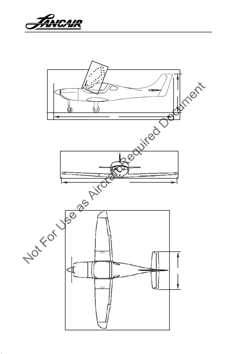
SIDE VIEW
Aircraft Length (x) for 550: 270.25; for 540: 274
Aicraft Height (y) for 550: 88.25; for 540: 90.5
FRONT VIEW
Note: Above dimension includes strobe lights.
Legacy
LEGACY THREE VIEW
y
x
25’ 8”
TOP VIEW
50.34
I-7February 2008

Legacy
I-9February 2008
Legacy
DESCRIPTIVE DATA
ENGINES
The Lancair Legacy is designed for either the Continental IO-550-N or the Lycom-
ing IO-540-V4A5 engines. Currently Lancair does not support or approve of any
other engines.
PROPELLERS
The approved propellers have been tested and the engine-propeller combinations
have Supplemental Type Certicates. Lancair does not approve of or support any
other propellers.
Propellers for the Continental IO-550-N:
BHC-J2YF-1BF/F7694-4TX
This is a 2-blade constant speed, 69” diameter propeller.
MTV-9-D/183-109
This is a 3-blade constant speed composite 72” diameter propeller.
Note the larger diameter and keep in mind the ground clearance is
reduced by 1-1/2”.
Propellers for the Lycoming IO-540-V4A5:
HC-F2YR-1F/F7694-4T
This is a 2-blade constant speed, 69” diameter propeller.
NOTE
Other propellers which are approved are listed
by Lancair and its dealers or are approved by
Supplemental Type Certificate
FUELS
Standard Fuel System Capacity ........... 64 gallons
Standard Fuel Type .............................. 100LL (Blue in Color)
I-8
February 2008

OIL CAPACITIES
IO-540-V4A5....................................... 8 quarts (U.S.)
IO-550-N.............................................. 8 quarts (U.S.)
CABIN AND ENTRY DIMENSIONS
Length - 45”
Height - 42.5”
Width - 41”
BAGGAGE
Compartment Volume: 11 ft.
3
Legacy
*Rudder Pedals all the way Forward
SPECIFIC LOADINGS (Max Take-off Wt)
Wing Loading:
At 2,200 lbs: 26.7 lbs./sq.ft.
Power Loading:
At 2,200 lbs.:
Lycoming IO 540 V4A5: ............8.5 lbs./hp
Contenintal IO 550-N: ..............7.1 lbs/hp
I-9February 2008

Legacy
I-11February 2008
Legacy
GENERAL AIRSPEED TERMINOLOGY AND
SYMBOLS
CAS Calibrated Airspeed is the indicated speed of an airplane, corrected
for “position error” and instrument error. Calibrated airspeed is equal
GS Ground Speed is the speed of an airplane relative to the ground.
IAS Indicated Air Speed is the speed of an airplane as shown on the air-
KCAS Calibrated Airspeed expressed in “knots”.
KIAS Indicated Airspeed expressed in “knots”.
TAS True Airspeed is the airspeed relative to undisturbed air which is the
VA Maneuvering Speed is the maximum speed at which application of
VFE Maximum Flap Extend Speed is the highest speed permissible with
to true airspeed in standard atmosphere at sea level.
speed indicator. IAS values published in this handbook assume zero
instrument error.
CAS corrected for altitude and temperature.
full available aerodynamic control will not overstress the airplane.
wing aps in a prescribed extended position.
VLE Maximum Landing Gear Extended Speed is the maximum speed at
which an airplane can be safely own with the landing gear extended.
VLO Maximum Landing Gear Operating Speed is the maximum speed at
which the landing gear can be safely extended or retracted.
VNE Never Exceed Speed is the speed limit that may not be exceeded at
any time.
VNO/VC Maximum Structural Cruising Speed is the speed that should not be
exceeded except in smooth air and then only with caution.
VS Stalling Speed or the minimum steady ight speed at which the air-
plane is controllable.
VSO Stalling Speed or the minimum steady ight speed at which the air-
plane is controllable in the landing conguration.
VX Best Angle-of-Climb Speed is the airspeed which delivers the greatest
gain of altitude in the shortest possible horizontal distance.
I-10
February 2008

Legacy
VY Best Rate-of-Climb Speed is the airspeed which delivers the greatest
gain in altitude in the shortest possible time.
METEOROLOGICAL TERMINOLOGY
ISA. International Standard Atmosphere in which
1) The air is a dry perfect gas;
2) The temperature at sea level is 15° Celsius (59° Fahrenheit);
3) The temperature gradient from sea level to the altitude at which
the outside air temperature is -56.5°C (-69.7°F) is -0.00198°C
(-0.003566°F) per foot and zero above that altitude.
OAT (Outside Air Temperature) The free air static temperature, obtained ei-
ther from inight temperature indicators adjusted for instrument error
and compressibility effects, or ground meteorological sources.
Pressure Altitude The altitude read from an altimeter when the barometric
subscale has been set to 29.92 inches Hg or 1013.2 millibars.
Station Pressure Actual atmospheric pressure at eld elevation.
Wind The wind velocities recorded as variables on the charts of this hand-
book are to be understood as the headwind or tailwind components of
the reported winds.
POWER TERMINOLOGY
Take-off and Maximum Continuous The highest power rating not limited by
time.
Cruise Climb The power recommended for cruise climb.
ENGINE CONTROLS/INSTRUMENTS
Throttle Control. Used to control power by introducing fuel-air mixture into
Propeller Control. Connected to the propeller governor. It is used to maintain
Mixture Control. This control is used to set fuel ow in all modes of operation
the intake passages of the engine. Settings are reected by readings
on the manifold pressure gauge or RPM for xed pitch propellers.
engine/propeller RPM at a selected value by controlling blade angle.
and cuts off fuel completely for engine shutdown.
I-11February 2008

Legacy
I-13February 2008
Legacy
EGT (Exhaust Gas Temperature). This indicator is used to identify the lean
and best power fuel ow for various power settings.
CHT (Cylinder Head Temperature). The indicator used to identify the oper-
ating temperature of the engines’ cylinder(s).
Tachometer. Indicates the RPM of the engine/ propeller.
Propeller Governor. Regulates the RPM of the engine by increasing or de-
creasing the propeller pitch through a pitch change mechanism in the
propeller hub.
AIRPLANE PERFORMANCE AND FLIGHT
PLANNING TERMINOLOGY
Climb Gradient. The ratio of the change in height during a portion of a climb,
to the horizontal distance traversed in the same time interval.
Demonstrated Crosswind Velocity. The demonstrated crosswind velocity is
the velocity of the crosswind component for which adequate control
of the airplane during take-off and landing was actually demonstrated.
The value shown is considered to be limiting. The value in this handbook is that demonstrated by Lancair test pilots and considered safe.
MEA. Minimum enroute IFR altitude.
Route Segment. A part of a route. Each end of that part is identied by:
1) a geographical location; or
2) a point at which a denite radio x can be established.
GPH. Gallons per hour fuel ow.
PPH. Pounds per hour fuel ow.
WEIGHT AND BALANCE TERMINOLOGY
Reference Datum. An imaginary vertical plane from which all horizontal dis-
tances are measured for balance purposes.
Station. A location along the airplane fuselage usually given in terms of dis-
tance from the reference datum.
Arm. The horizontal distance from the reference datum to the center of gravity
(GG) of an item.
I-12
February 2008

Legacy
Moment. The product of the weight of an item multiplied by its arm. (Moment
divided by a constant may be used to simplify balance calculations by
reducing the number of digits).
Airplane Center of Gravity (CG). The point at which an airplane would bal-
CG Arm. The arm obtained by adding the airplane’s individual moments and
CG limits. The extreme center of gravity locations within which the airplane
Usable Fuel. The fuel available for ight planning purposes.
Unusable Fuel. Fuel remaining after a runout test has been completed.
Standard Empty Weight. Weight of a standard airplane including unusable
Basic Empty Weight. Standard empty weight plus any optional equipment.
Useful Load. Difference between take-off weight, or ramp weight if applicable,
ance if suspended. Its distance from the reference datum is found by
dividing the total moment by the total weight of the airplane.
dividing the sum by the total weight.
must be operated at a given weight.
fuel, full operating uids and full oil.
and basic empty weight.
Maximum Take-off Weight. Maximum weight approved for the start of the
take-off run.
Maximum Landing Weight. Maximum weight approved for the landing
touchdown.
Maximum Zero Fuel Weight. The maximum allowable weight of the aircraft
without fuel. In other words, the weight of aircraft minus the fuel on
board should not exceed this gure.
Tare. The weight of chocks, blocks, stands, etc. used on the scales when weigh-
ing an airplane.
Jack Points. Points on the airplane identied by the manufacturer as suitable
for supporting the airplane for weighing or other purposes.
I-13February 2008

I-15February 2008
Legacy
NOTES:
Legacy
I-14
February 2008

NOTES:
Legacy
I-15February 2008

II-1February 2008
Legacy
NOTES:
Legacy
I-16
February 2008

Legacy
LIMITATIONS
S
GENERAL . . . . . . . . . . . . . . . . . . . . . . . . . . . . . . . . . . . . . . . . . . . . . . . . .II-3
AIRCRAFT OPERATING SPEEDS . . . . . . . . . . . . . . . . . . . . . . . . . . . . .II-3
POWERPLANT LIMITATIONS . . . . . . . . . . . . . . . . . . . . . . . . . . . . . . . .II-3
OPERATING LIMITATIONS . . . . . . . . . . . . . . . . . . . . . . . . . . . . . . . . . .II-4
POWERED BY IO-550-N ENGINE . . . . . . . . . . . . . . . . . . . . . . . . . . . . .II-4
POWERED BY IO-540-V4A5 ENGINE . . . . . . . . . . . . . . . . . . . . . . . . .II-4
FUEL GRADES (AVIATION GASOLINE) . . . . . . . . . . . . . . . . . . . . . . . . . . . .II-5
OIL SPECIFICATION . . . . . . . . . . . . . . . . . . . . . . . . . . . . . . . . . . . . . . . .II-5
HYDRAULIC PRESSURE . . . . . . . . . . . . . . . . . . . . . . . . . . . . . . . . . . . .II-6
WEIGHT LIMITS . . . . . . . . . . . . . . . . . . . . . . . . . . . . . . . . . . . . . . . . . . . .II-6
CENTER OF GRAVITY LIMITS: . . . . . . . . . . . . . . . . . . . . . . . . . . . . . . .II-6
MEAN AERODYNAMIC CHORD . . . . . . . . . . . . . . . . . . . . . . . . . . . . . .II-6
MANEUVER LIMITS . . . . . . . . . . . . . . . . . . . . . . . . . . . . . . . . . . . . . . . .II-6
DEMONSTRATED MANEUVERS . . . . . . . . . . . . . . . . . . . . . . . . . . . . . .II-7
FLIGHT LOAD FACTOR LIMITS . . . . . . . . . . . . . . . . . . . . . . . . . . . . . .II-7
TYPES OF OPERATIONS AND LIMITS . . . . . . . . . . . . . . . . . . . . . . . . .II-8
FUEL QUANTITIES . . . . . . . . . . . . . . . . . . . . . . . . . . . . . . . . . . . . . . . . .II-8
FUEL MANAGEMENT . . . . . . . . . . . . . . . . . . . . . . . . . . . . . . . . . . . . . . .II-8
SEATING . . . . . . . . . . . . . . . . . . . . . . . . . . . . . . . . . . . . . . . . . . . . . . . . . .II-9
WINTER OPERATIONS . . . . . . . . . . . . . . . . . . . . . . . . . . . . . . . . . . . . . .II-9
PLACARDS . . . . . . . . . . . . . . . . . . . . . . . . . . . . . . . . . . . . . . . . . . . . . . . .II-9
NOTES: . . . . . . . . . . . . . . . . . . . . . . . . . . . . . . . . . . . . . . . . . . . . . . . . . . .II-12
ECTION
T
ABLE OF CONTENTS
II
II-1February 2008

Legacy
II-3February 2008
Legacy
Intentionally Left Blank
II-2
February 2008

Legacy
GENERAL
The data approved by Lancair International, Inc. and the Limitations presented
herein are those established by Lancair as applicable to the Lancair Legacy.
This section follows the format approved by the GAMA Specication #1, and is
intended to provide operating guidelines and limitations specic to the Lancair
aircraft only. All airspeeds quoted are given conventional nomenclature, are shown
in knots, calibrated airspeed, and assume zero instrument error.
NOTE
It is imperative that you calibrate your airspeed
system (static and pitot) to provide the corrections
to the values shown below in KCAS. If there is
instrument (gauge) error that needs to be factored
in also to reach KIAS.
AIRCRAFT OPERATING SPEEDS
Lancair Legacy
SPEED MARKING KCAS
Never Exceed Speed VNE Red Line 274
Maneuvering Speed VA 170 @ Gross 2200 lbs.
158 @ 1900 lbs.
140 @ 1500 lbs.
Normal Oper Range VNO Green Arc 220
Full Flap Oper Range VFE White Arc 120
Flaps 10O or less 170
POWERPLANT LIMITATIONS
Engines
The Lancair Legacy is powered by standard aircraft engines, the power varying
from 260 to 325 HP. They are horizontally opposed, air cooled, six cylinder engines
made by Textron Lycoming and Teledyne Continental.
II-3February 2008

Legacy
II-5February 2008
Legacy
OPERATING LIMITATIONS
Operating limitations for the engines supported by Lancair for use in the Lancair
Legacy are shown below. If your engine differs, you must account for that. In
addition, the data and limits shown is for new specification engines and does not
reflect any degradation due to age or number and quality of overhauls.
Performance will vary obviously depending on the engine/propeller combination
as well. Fixed pitch propellers will have significant effects on takeoff and cruise
capabilities, for example.
Lancair Legacy Powered by IO-550-N Engine
Specication:
Max Continuous RPM
310 hp at 2700 rpm
77% Cruise, 240 hp at 2500 rpm
Cylinder Heat Temperatures
Maximum (short time period), 460°F (238 °C)
Recommended Max Temperature @ Cruise 380°F.
Oil Temperatures
Maximum, 240°F (115°C)
Normal, 170°F-200°F
Minimum (take-off), 100°F
Oil Pressure
Maximum (cold), 100 psi
Normal Operation, 30-60 psi
Minimum Operating (idle), 10 psi
Fuel Flow
max., .52 BSFC/26.7 gph
77% cruise, .46 BSFC/18.7 gph
Vacuum Pressure
Normal Operating Range, 4.8 - 5.2 in.hg.
Lancair Legacy Powered by IO-540-V4A5 Engine
Specication:
Maximum Continuous RPM
260 hp at 2700 rpm (.51 BSFC)
75% Rated Power, 195 hp @ 2450 rpm (15 gph)
II-4
February 2008

60% Rated Power, 155 hp @ 2350 rmp (12.0 gph)
Cylinder Head Temperatures
Maximum (short time period), 500°F (260°C)
Maximum (above 75%), 475°F
Maximum (below 75%, 435%
Oil Temperatures
Maximum, 245°F
Normal, 180°F-220°F
Minimum (takeoff) 90°F
Oil Pressures
Maximum, starting & warm up, 115 psi
Normal Operation, 55-95 psi
Minimum Operating (idle), 25 psi
Fuel Pressure (at engine driven fuel pump)
Maximum, 35 psi
Minimum, 12 psi
Fuel Pressure (at inlet to fuel injector)
Maximum, 45 psi
Minimum, 14 psi
Vacuum Pressure
Normal Operating Range, 4.8-5.2 in.Hg.
Legacy
FUEL GRADES (Aviation Gasoline)
Only 100LL. Blue in Color.
OIL SPECIFICATION
Follow the engine manufacturer’s recommendations. Following initial break-in
of the engine it should be operated with an ashless dispersant oil (MIL-L-22851)
conforming to the applicable engine handbook. Break-in (the first 50 hours or until
oil consumption has stabilized) should be accomplished using a corrosion preventative oil or straight mineral oil. Low power settings (less than 65-75%) should be
avoided during the break-in period and the oil level checked frequently.
Also Refer to Engine Handbook.
OIL TEMPERATURE
Caution (Yellow Radial) ...................... 200 to 240°F
Normal Oper Range (Green arc).......... 140 to 190°F
Maximum (Red radial) ........................ 245°F
II-5February 2008

Legacy
II-7February 2008
Legacy
HYDRAULIC PRESSURE
(Not normally monitored)
Gear up................................................. Approximately 1000 psi.to1,200 psi
Gear down............................................ Approximately 600 psi
WEIGHT LIMITS
Maximum Take-off Weight.................. 2200 lbs
Maximum Landing Weight .................. 2200 lbs
Maximum Zero Fuel Weight................1900 lbs
Standard Empty Weight .......................1450 lbs
* Maximum Baggage Weight .............. 75 lbs
* Check your C.G. calculations.
CENTER OF GRAVITY LIMITS:
Refer to Section VI.
MEAN AERODYNAMIC CHORD
The center of gravity (CG) is referenced in terms of the mean aerodynamic chord.
Refer to section VI for the weight and balance instructions.
MANEUVER LIMITS
The Lancair Legacy is licensed as EXPERIMENTAL. Spins are not recommended.
Aerobatic maneuvers which have been flown by Lancair test pilots are shown in
the chart below. Care must be used and smooth control inputs used at all times
when performing aerobatics, and instruction in the maneuvers is considered virtually mandatory. A parachute is FAA required, and no baggage should be carried
while performing aerobatics. A thorough preflight should be conducted for loose
items in the aircraft, and in the cockpit in particular. Another thorough post flight
inspection of the aircraft is also recommended.
II-6
February 2008

Legacy
DEMONSTRATED MANEUVERS
WARNING: AEROBATICS NOT APPROVED
MANEUVER ENTRY SPEED MAX G’S
Chandelle 140 Kts 1.5
Lazy Eight 170 Kts 1.5
Stalls (not whip stalls)* - 0.0 to 1.5
Aileron Rolls* 180 Kts -1.0* to 1.0
Barrel Rolls 200 Kts 1.0
Split-S 100 Kts 3.5
* WARNING
Since these engines do not have an inverted oil system
extreme care must be used during low or negative
“G” maneuvers. Lack of oil pressure will cause the
propeller to go to flat pitch and engine overspeed will
result. Transient oil pressure conditions near zero
must be limited to less than two (2) seconds.
NOTE
Speeds shown are calibrated. Corrections must
be applied from a calibration of your aircraft to
determine your proper entry indicated airspeeds.
All pilots are again reminded that instruction in
aerobatics in the Lancair is highly desirable. Speed
buildup during these maneuvers can be rapid and
proper control usage is essential throughout the
maneuver to remain within 1imits.
FLIGHT LOAD FACTOR LIMITS
Flaps up, at gross weight ..................... +4.4, to -2.2 g’s
Flaps down, at gross weight................. +2 to 0 g’s
II-7February 2008

Legacy
II-9February 2008
Legacy
TYPES OF OPERATIONS AND LIMITS
The Lancair Legacy is approved for the following types of flight when the required
equipment is installed and operations are conducted as defined in the LIMITATIONS
section.
1. VFR, day and night
2. IFR, day and night
WARNINGS
1. Flight operations with passengers for hire
and
2. Flight into known icing is prohibited.
FUEL QUANTITIES (Approx.)
Left Wing............................................. 32.0 U.S. gallons
Right Wing........................................... 32.0 U.S. gallons
NOTE:
Fuel quantity may vary slightly from aircraft to
aircraft.
FUEL MANAGEMENT
The Lancair Legacy has two fuel tanks - a left and a right wing fuel tank. The
fuel selector valve installed in the center console allows you to select between the
left or tight tanks or shut the fuel off. Wing tank selection is typically managed
by switching every 30 minutes to keep the aircraft within trim.
The electric fuel boost pump is used for starting the engine (high boost). The primary difference between the Lycoming and Continental fuel systems is the use of
a single stage electric boost pump for the Lycoming installations and a dual stage
for the Continental.
Lycoming installations: Electric boost only has a high boost option. Used for
priming prior to engine start, takeoff and emergencies.
Contintal installations: Electric high boost and electric low boost. The electric
high boost is used for priming the engine and emergencies. The low boost is used
for vapor suppression at high altitudes.
II-8
February 2008
 Loading...