


PILOT'S
OPERATING
HANDBOOK
AND
AIRPLANE FLIGHT MANUAL
®
ES-P
Manufacturer: Heizer IJ
Serial No: 001
Model: ESP
Lancair Kit No: 120
This aircraft is FAA Approved in the EXPERIMENTAL
category based on FAR 23. This document must be carried in
the aircraft.

Originally Published by
Lancair International Inc.
2244 Airport Way
Redmond, Oregon 97756
Adapted for Heizer IJ ESP Serial Number 001 by
Isaac Heizer
Woodinville, Washington
98072
WARNING
This is an experimental aircraft having
experimental documentation. No aspect
of this documentation can be assumed
correct. The pilot must accept all risk and
responsibility associated with being
anywhere near this airplane – do not fly in
this aircraft if you do not personally agree
and accept all responsibility!

INTRODUCTION
This Pilot’s Operating Handbook is in the format and contains most
data recommended in the GAMA (General Aviation Manufacturers
Association) Handbook Specification Number 1.
Use of the Terms Warning, Caution and Note
The following conventions will be used for the terms, Warning,
Caution, and Note.
WARNING
The use of a Warning symbol means that
information which follows is of critical
importance and concerns procedures and
techniques which could cause or result in
personal injury or death if not carefully
followed.
CAUTION
The use of a Caution symbol means that
information which follows is of significant
importance and concerns procedures and
techniques which could cause or result in
damage to the airplane and/or its
equipment if not carefully followed.
NOTE
The use of the term “NOTE” means the
information that follows is essential to emphasize.

Lancair ES-P
HANDBOOK
SECTION 2 GENERAL
SECTION 3 LIMITATIONS
SECTION 4 EMERGENCY PROCEDURES
SECTION 5 NORMAL PROCEDURES
SECTION 6 WEIGHT & BALANCE
SECTION 7 SYSTEMS DESCRIPTIONS
SECTION 8 HANDLING, SERVICING &
MAINTENANCE
SECTION 9 SUPPLEMENTS
SECTION 10 SAFETY INFORMATION
SECTION 11 ADDENDUM

SECTION 2 GENERAL
TABLE OF CONTENTS
IMPORTANT NOTICE......................................................................2
DESCRIPTIVE DATA........................................................................4
GENERAL AIRSPEED TERMINOLOGY AND SYMBOLS........7
METEOROLOGICAL TERMINOLOGY....................................... 8
POWER TERMINOLOGY................................................................ 9
ENGINE CONTROLS / INSTRUMENTS........................................9
PERFORMANCE AND FLIGHT PLANNING TERMINOLOGY
.............................................................................................................10
WEIGHT AND BALANCE TERMINOLOGY.............................. 11

This is a state-of-the-art, high performance general aviation aircraft.
Its performance is spectacular and its life almost beyond measure when
given reasonable care. You must become familiar with this handbook
as well as the FARs that are applicable to its operation. The
combination will provide you with safe and sound knowledge for
operation of your personally manufactured Lancair.
IMPORTANT NOTICE
This handbook must be read carefully by the owner or operator(s) of
this aircraft in order to become familiar with its operation and to obtain
all it has to offer in terms of both speed and reliability. Herein are
suggestions and recommendations to help you obtain safe performance
without sacrificing economy. You are encouraged to operate your
machine in accordance with and within the limits identified in this
Pilot's Operating Handbook as well as any placards located in the
airplane.
Again, the operator should be familiar with the Federal Aviation
Regulations as applicable to the operation and maintenance of
experimental airplane and FAR Part 91 General Operating and Flight
Rules. The aircraft must be operated and maintained in accordance
with any FAA Airworthiness Directives that may be issued against it.
It is also prudent and mandatory to operate within any established
limits or Service Bulletins.
The FARs place the responsibility for the maintenance of this airplane
on the owner and the operator who must ensure that all maintenance is
accomplished by the owner or qualified mechanics in conformity with
all airworthiness requirements established for this airplane.
All limits, procedures, safety practices, time limits, servicing, and
maintenance requirements contained in this handbook are considered
mandatory for the continued airworthiness of this airplane, in a
condition equal to that of its original manufacture.
NOTE
Except as noted, all airspeeds quoted in this
handbook are Indicated Airspeeds (IAS) in Knots
and assume zero instrument error.

The owner/operator should frequently refer to all supplements, whether
STCs (Supplemental Type Certificate) or Lancair Supplements direct
from Lancair, for appropriate placards, limitations, normal, emergency
and other operational procedures for proper operation of their Lancair
with any optional equipment installed.
WARNING
When this handbook is used for airplane
operational purposes, it is the pilot's responsibility
to maintain it in current status.

DESCRIPTIVE DATA
ENGINE
This aircraft is fitted with a Continental TSIO-550E (3) six cylinder
fuel injected twin-turbocharged engine.
PROPELLER
This aircraft is equipped with an MT MTV-9-D/198-58a 3 blade
hydraulic constant speed propeller with a McCauley C290D3-R/T43
propeller governor. The propeller is 77.9 inches diameter.
FUELS
100 or 100LL (Minimum grade Aviation Gasoline conforming to
ASTM D0-76 & MLG-5572, latest revision).
SYSTEMS CAPACITIES
Fuel capacity 105 US gallons
Oil Capacity 12 quarts
FILTERS
Oil Filter CH48109-1
WEIGHTS
Empty weight 2480 lbs.
Max gross take-off 3600 lbs.
Max landing weight 3550 lbs.
Max weight in baggage compartment 175 lbs.
CABIN DIMENSIONS
Length 74 inches
Height (max) 47 inches
Width
Front seat 45 inches
Rear seat 42 inches
BAGGAGE
Length 40 inches
Width (Front) 37 inches
Width (Rear) 22.5 inches
Height (Front) 29.5 inches
Height (Rear) 23 inches

SPECIFIC LOADING (max take-off weight)
Wing area 140 ft2
Wing loading 25.7 lb./ft2
Power loading (350 HP) 10.3 lb./h.p.
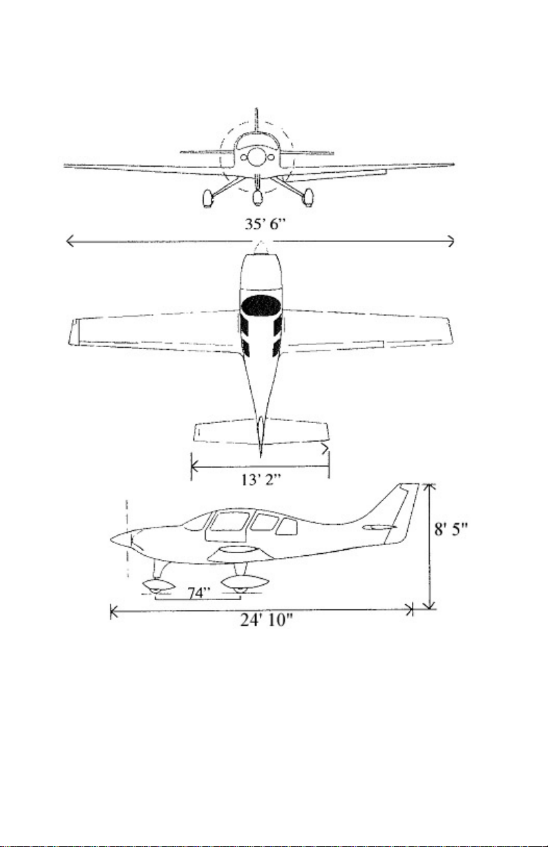
Basic Airframe Dimensions

GENERAL AIRSPEED TERMINOLOGY
AND SYMBOLS
CAS
GS
IAS
KCAS
KIAS
TAS
VA
VFE
Calibrated Airspeed is the indicated speed of an
airplane, corrected for position error and
instrument error. Calibrated Airspeed is equal to
true airspeed in standard atmosphere at sea level.
Ground Speed is the speed of an airplane relative
to the ground.
Indicated Air Speed is the speed of an airplane as
shown on the airspeed indicator when corrected for
instrument error. IAS values published in this
handbook assume zero instrument error.
Calibrated Airspeed expressed in knots.
Indicated Airspeed expressed in knots.
True Airspeed is the airspeed of an airplane
relative to undisturbed air which is the CAS
corrected for altitude, temperature and
compressibility.
Maneuvering Speed is the maximum speed at
which application of full available aerodynamic
control will not over stress the airplane.
Maximum Flap Extend Speed is the highest speed
permissible with wing flaps in a prescribed
extended position.
VN
VNE
VNO/VC
VS
VSO
Maximum Level Speed at full power.
Never Exceed Speed is the speed limit that may
not be exceeded at any time.
Maximum Structural Cruising Speed is the speed
that should not exceeded except in smooth air, and
then only with caution.
Stalling Speed or the minimum steady flight speed
at which the airplane is controllable.
Stalling Speed or the minimum steady flight speed
at which the airplane is controllable in the landing
configuration.

VX
Best Ange-of-Cimb Speed is the airspeed that
delivers the greatest gain of altitude in the shortest
possible horizontal distance.
VY
MMO
Best Rate-of-Climb Speed is the airspeed that
delivers the greatest gain in altitude in the shortest
possible time.
Maximum Mach number.
METEOROLOGICAL TERMINOLOGY
ISA International
Standard
OAT (Outside Air
Temperature)
Atmosphere in which:
1) The air is a dry perfect gas;
2) The temperature at sea level is 15
Celsius (59° Fahrenheit);
3) The pressure at sea level is 29.92
in. Hg. (1013.2 millibars);
4) The temperature gradient from sea
level to the altitude at which the
outside air temperature is -56.5ºC (-
69.7ºF) is -0.00198°C (-0.003566ºF)
per foot and zero above that altitude.
The free air static temperature,
obtained either from inflight
temperature indicators adjusted for
instrument error and compressibility
effects, or ground meteorological
sources.
Indicated Pressure
Altitude
The number actually read from an
altimeter when the barometric
subscale has been set to 29.92 in Hg
or 1013.2 millibars.

Pressure Altitude
Altitude measured from standard sealevel pressure (29.92 in Hg) by a
pressure or barometric altimeter. It
is the indicated pressure altitude
corrected for position and instrument
error. In this handbook altimeter
instrument errors are assumed to be
zero. Position errors may be
obtained from the Altimeter
Correction Graph.
Station Pressure
Wind
Actual atmospheric pressure at field
elevation.
The wind velocities recorded as
variables on the charts of this
handbook are to be understood as the
headwind or tailwind components of
the reported winds.
POWER TERMINOLOGY
Takeoff /Maximum
Continuous
Cruise Climb
The highest power rating not limited
by time.
The power recommended for cruise
climb.
ENGINE CONTROLS / INSTRUMENTS
Throttle Control
Used to control power by introducing
fuel-air mixture into the intake
passages of the engine. Settings are
reflected by readings on the manifold
pressure gauge.
Propeller Control
Mixture Control
This control requests the propeller to
maintain engine / propeller rpm at a
selected value by controlling blade
angle.
This control is used to set fuel flow in
all modes of operation and cuts off
fuel completely for engine shutdown.

CHT (Cylinder
Head Temperature)
The indicator used to identify the
operating temperature of the engines'
cylinder(s).
TIT
Tachometer
Propeller Governor
The temperature of the exhaust gases
as they enter the respective
turbocharger.
Indicates the rpm of the
engine/propeller.
Regulates the rpm of the
engine/propeller by increasing or
decreasing the propeller pitch
through a pitch change mechanism in
the propeller hub.
PERFORMANCE AND FLIGHT PLANNING
TERMINOLOGY
Climb Gradient
Demonstrated
Crosswind Velocity
The ratio of the change in height
during a portion of a climb, to the
horizontal distance traversed in the
same time interval.
The demonstrated crosswind velocity
is the velocity of the crosswind
component for which adequate
control of the airplane during takeoff and landing was actually
demonstrated. The value shown is
considered to be limiting. The value
in this handbook is that demonstrated
by Lancair test pilots and considered
safe.
MEA
Route Segment
GPH
Minimum enroute IFR altitude.
A part of a route. Each end of that
part is identified by
1) a geographical location; or
2) a point at which a definite radio
fix can be established.
Gallons per hour fuel flow.

WEIGHT AND BALANCE TERMINOLOGY
Reference Datum
Station
Arm
Moment
Airplane Center of
Gravity (CG)
CG Arm
An imaginary vertical plane from
which all horizontal distances are
measured for balance purposes.
A location along the airplane fuselage
usually given in terms of distance from
the reference plane.
The horizontal distance from the
reference datum to the center gravity
(CG) of an item.
The product of the weight of an item
multiplied by its arm. (Moment
divided by a constant may be used to
simplify balance calculations by
reducing the number of digits).
The point at which an airplane would
balance if suspended. Its distance
from the reference datum is found by
dividing the total moment by the total
weight of the airplane.
The arm obtained by adding the
airplane's individual moments and
dividing the sum by the total weight.
CG Limits
Usable Fuel
Unusable Fuel
Standard Empty
Weight
Basic Empty
Weight
The extreme center of gravity
locations within which the airplane
must be operated at a given weight.
The fuel available for flight planning
purposes.
Fuel remaining after a run out test has
been completed in accordance with
governmental regulations.
Weight of a standard airplane
including unusable fuel, full operating
fluids and full oil.
Standard empty weight plus any
optional equipment.

Payload Weight
Weight of occupants, cargo and
baggage.
Useful Load
Difference between take-off weight or
ramp weight (if applicable) and basic
empty weight.
Maximum Ramp
Weight
Maximum weight approved for ground
maneuvering. (It includes weight of
start, taxi and run up fuel).
Maximum TakeOff Weight
Maximum Landing
Weight
Zero Fuel Weight
Tare
Maximum weight approved for the
start of the take-off run.
Maximum weight approved for the
landing touchdown.
Weight exclusive of usable fuel.
The weight of chocks, blocks, stand,
etc. used on the scales when weighing
an airplane.
Jack Points
Points on the airplane identified by the
manufacturer as suitable for
supporting the airplane for weighing
or other purposes.

Section 3 LIMITATIONS
TABLE OF CONTENTS
AIRCRAFT OPERATING SPEEDS.................................................2
ALTITUDE LIMITATION...............................................................3
POWERPLANT OPERATING LIMITATIONS.............................. 3
OIL SPECIFICATION......................................................................4
POWERPLANT INSTRUMENT MARKINGS................................4
MAXIMUM WEIGHTS (LBS)......................................................... 4
CENTER OF GRAVITY LIMITS .................................................... 4
FLIGHT LOAD FACTOR LIMITS .................................................. 5
KINDS OF OPERATION LIMITS AND PILOT REQUIREMENTS
...........................................................................................................5
ICING CONDITIONS.......................................................................5
COMMERCIAL OPERATIONS ...................................................... 5
FUEL MANAGEMENT ................................................................... 5
SEATING CAPACITY..................................................................... 5
WINTER OPERATIONS.................................................................. 5

AIRCRAFT OPERATING SPEEDS
The airspeed is shown on both the PFD and backup airspeed indicator.
The airspeed on the PFD is indicated with an airspeed tape and colored
bands. The backup airspeed indicator has four colored arcs on the outer
circumference.
SPEED SYMBOL KIAS
Caution, smooth air only Yellow
174-220
Arc
Never exceed speed
Decrease 4.4 knots for
Red Line,
VNE
220
163 @ FL250
each 1000 ft above
12,000’ pressure altitude
Normal Operating Range Green Arc 67 - 174
Maneuvering Speed
Decrease 3 knots for each
1000 ft. above 1200 feet
pressure altitude
VA 135 @ 2600 lbs
96 @ 2600 (FL250)
158 @ 3600 lbs
119 @ 3600 (FL250)
Max. Structrual Cruising
VNO 174
Speed
Decrease 3.5 knots for
each 1000’ above 12,000’
pressure altitude
Full Flap Operating Range White Arc 56 - 122
Maximum Flap Extended
VFE 122
Speed
Decrease 2.4 knots for
each 1000’ above 12,000’
pressure altitude
Best Angle of climb speed VX 85
Best Rate of climb speed VY 105
Stall Speed clean VS1 74
Stall Speed landing
VSO 61
configuration
Max. Demonstrated x-wind component 15

ALTITUDE LIMITATION
The maximum flight altitude is 25,000 MSL with a working oxygen
system and 14,000 MSL without oxygen available. This is to ensure
backup oxygen is available in the event of pressurization system
failure.
POWERPLANT OPERATING LIMITATIONS
Operating limitations for the TSIO-550E engine in this aircraft are
listed below. In addition, the data and limits shown are for new
specification engines and do not reflect any degradation due to age or
number and quality of overhauls.
Rated max continuous BHP 350 HP @ 2700
RPM
Recommended Max.cruising BHP 262 HP @ 2500
RPM
Max continuous manifold pressure 38.5” Hg.
Cylinder Head Temperatures - °F
Normal flight operation max temperature 420°F
Maximum a llowable 460°F
Turbine Inlet Temperature - °F
Maximum a llowable 1750
1850 for
30 sec
Oil Temperatures - °F
Maximum 240
Minimum for take-off 100
Cruise 160-200
Oil Pressure - PSI
Normal operation at 75oF – 240oF 30-60
Idle, Minimum 10
Max Allowable (cold oil) 100
Fuel Pressure (Unmetered p.s.i.g.)
Idle (700 RPM) 7.0 - 9.0
Takeoff 32 - 34
Fuel Flow (GPH)
Takeoff 41.7 – 43.4

OIL SPECIFICATION
Lubricating oil used must conform to Teledyne Continental Motors’
specification MHS24.
All Temperatures 15W50 or 20W50
Below 40°F ambient (Sea Level) SAE30 or 10W30
Above 40°F Ambient (Sea Level) SAE50 or 20W60
POWERPLANT INSTRUMENT MARKINGS
The engine instrumentation area of the Garmin G900X in this aircraft
contains the following markings:
OIL TEMPERATURE (DEG. F.)
Caution (Yellow region) 210-240
Normal Operating range (Green region) 160-200
Maximum (Red line) 240
OIL PRESSURE (PSI)
Minimum (Idle, Red line) 10
Caution Range (Yellow region) 10-30
Operating Range (Green region) 30-60
Maximum (Red Line ) 100
TACHOMETER (RPM)
Operating Range (Green region) 600-2700
Maximum (Red Line ) 2700
MANIFOLD PRESSURE (IN. HG.)
Operating Range (Green region) 15-38
Maximum (Red Radial) 38-38.5
FUEL PRESSURE (PSIG)
Operating Range (Green region) 10-34
Maximum Pressure (Red Radial) 34
FUEL QUANTITIES
Standard Fuel 105 US Gal.
MAXIMUM WEIGHTS (LBS)
Max gross take-off 3600
Max landing weight 3550
Max weight in baggage compartment 175
CENTER OF GRAVITY LIMITS
The allowable Center of Gravity (CG) range is from Fuselage Station
(FS) 95.4 to (FS) 105 or 6.6 to 26% MAC.

The aft CG limit must be considered a firm limit. Loads that place the
CG further aft are dangerous and must not be accepted. A “Weight
and Balance" sheet must be completed and carried in the aircraft at all
times.
REFERENCE DATUM
The Datum is located at FS “0.” This can be located by measuring
51.25” forward from the bottom forward face of the firewall.
FLIGHT LOAD FACTOR LIMITS
Flaps Up +4.4, to -2.2 g's.
Flaps Down +2.2, to -0 g's
KINDS OF OPERATION LIMITS AND PILOT REQUIREMENTS
The airplane has the necessary equipment available for daytime and
nighttime VFR and IFR operations with only one pilot. The operational
minimum equipment and instrumentation for the kinds of operation are
detailed in Part 91 of the FARs.
ICING CONDITIONS
Flight into known icing is prohibited.
COMMERCIAL OPERATIONS
Flight operations with passengers for hire are prohibited.
FUEL MANAGEMENT
Do not take off with less than 10 gallons in each tank. There is no
interconnection between the wing tanks.
SEATING CAPACITY
This aircraft has capacity for four persons (one pilot and three
passengers).
WINTER OPERATIONS
Winter Operations are acceptable with proper oil grades for the
operating temperatures. Engine pre-heating is recommended when the
engine has been exposed to temperatures below 20 degrees Farenheit in
excess of two hours.


Section 4 EMERGENCY PROCEDURES
TABLE OF CONTENTS
EMERGENCY AIRSPEEDS ............................................................. 2
ENGINE FAILURE ............................................................................ 3
ENGINE FAILURE DURING TAKE-OFF (NOT ARIB ORNE)..... 3
ENGINE FAILURE IMMEDIATELY AFTER TAKEOFF (Below
400 Feet AGL)................................................................................... 3
ENGINE FAILURE DURING FLIGHT........................................... 3
IN-FLIGHT RESTART.....................................................................4
ROUGH RUNNING ENGINE.......................................................... 4
TURBOCHARGER FAILURE......................................................... 5
HIGH CYLINDER HEAD TEMPERATURE.................................. 7
HIGH OIL TEMPERATURE............................................................7
LOW OIL PRESSURE...................................................................... 8
ENGINE FIRE IN FLIGHT..............................................................8
ENGINE FIRE DURING START.....................................................9
EMERGENCY DESCENT ............................................................... 9
MAXIMUM GLIDE CONFIGURATION........................................ 9
FORCED LANDING........................................................................9
SYSTEMS EMERGENCIES............................................................10
ELECTRICAL SYSTEM PROBLEMS.......................................... 10
CIRCUIT BREAKERS AND FUSES......................................... 10
ELECTRICAL SYSTEM OVERCHARGING ........................... 11
ALTERNATOR FAILURE......................................................... 11
FLIGHT WITH ONE FAILED ELECTRICAL SYSTEM ......... 11
ELECTRIC TRIM / AUTOPILOT FAILURE............................12
MULTI-FUNCTION DISPLAY.................................................13
PRIMARY FLIGHT DISPLAY..................................................13
CARBON MONOXIDE ALERT....................................................13
WING FIRE IN FLIGHT................................................................13
PROPELLER OVERSPEED........................................................... 13
PROPELLER DAMAGE................................................................ 14
SPEED BRAKES............................................................................14
UNLATCHED DOOR IN FLIGHT................................................ 14
SPINS..............................................................................................14
EMERGENCY SPEED REDUCTION........................................... 15
LOSS OF PRESSURIZATION....................................................... 15
CRASH AX..................................................................................... 15

NOTE
All airspeeds quoted in this section are indicated
airspeeds (KIAS) and assume zero instrument
error.
EMERGENCY AIRSPEEDS
Emergency Descent
Idle Power, Flaps up, Speed Brakes
deployed
Best Glide – Flaps UP
Flaps Down
Speed brakes retracted
Landing Approach (W/O Power)
FLAPS UP 98 – 108 KIAS
FLAPS LANDING POSITION 80 – 90 KIAS
NOTE
The following checklists are presented to capture
in a compact format those pilot tasks requiring
rapid action. The pilot should keep these
checklists handy for ready access, and he should
familiarize him/herself with them before flying the
aircraft. Knowledge of the switches, controls,
gauges, etc. located quickly (even blindfolded) is
highly desirable. “Cockpit, time" prior to ever
flying or after an absence is time prudently spent.
Where more time would likely be available,
rationale will be added and alternative choices
offered. It must be remembered, however, that
each situation will be unique in some manner and
must be treated accordingly.
165 KIAS
100 KIAS
90 KIAS
AOA 2 GREEN

ENGINE FAILURE
ENGINE FAILURE DURING TAKE-OFF (NOT ARIBORNE)
Sufficient Runway remaining:
Throttle IDLE
Brakes APPLY as necessary
Flaps UP
Boost Pump OFF
Mixture CUTOFF
Fuel Selector OFF
Ignition OFF
Master Switches OFF
ENGINE FAILURE IMMEDIATELY AFTER TAKEOFF (Below
400 Feet AGL)
Airspeed 95 with flaps in takeoff
Boost Pump OFF
Mixture IDLE CUT-OFF
Fuel Selector OFF
Ignition OFF
Flaps LANDING position
Master Switches OFF
Maintain directional control and make only shallow turns to avoid
obstacles.
ENGINE FAILURE DURING FLIGHT
Airspeed BEST GLIDE (100
SpeedBrakes RETRACTED
Boost Pump LOW
Mixture RICH
Fuel Selector SWITCH TANKS
Alternate Air OPEN
Ignition VERIFY ON
If power is restored and there is any doubt as to the
cause of the engine stoppage, land at the nearest
airport and determine the cause.
position
100 KIAS with flaps up
KIAS with flaps up)
NOTE

IN-FLIGHT RESTART
CAUTION
Actual shutdown of an engine for practice or
training purposes should not be done. Engine
failure simulation should be done by reducing
power.
1 MASTER switch ON
2 Mixture ¾ FULL RICH
3 Fuel Selector FULLEST TANK
4 Fuel Boost Pump HIGH
5 Magnetos BOTH
6 Throttle NORMAL START POSITION
7 Start Switch START (if propeller is not
8 Throttle
9 Oil Press, Temp,
CHT
10 Power AS REQUIRED.
ROUGH RUNNING ENGINE
(open 1 in.)
turning)
a. Oil Pressure – Within
limits, will probably be
quite low if oil is cold.
If no oil pressure
indicated, engine
damage may occur if
restart is continued.
b. Throttle – Adjust to
15-20 inches manifold
pressure until engine
temperature reaches
operating range. Adjust
mixture as required.
c. Oil Pressure –
STABILIZED
d. Mixture – ¾ FULL
RICH
AS NECESSARY TO PREVENT
OVERSPEED.
Warm up at 15-20” manifold
pressure. Adjust mixture as
required for smoothness.
NORMAL INDICATION

Observe engine for visible damage or evidence of smoke or flame.
Extreme roughness may be indicative of propeller blade problem.
Mixture ADJUST as appropriate to power setting
being used. Do not arbitrarily go to Full
Rich as the roughness may be caused by
an over rich mixture
Magnetos ON
Low Boost ON (if above 10000 feet)
High Boost OFF
If engine roughness does not disappear after the above, the following
steps should be taken to evaluate the ignition system.
Alternate Air OPEN
Throttle REDUCE power until roughness
becomes minimal
Magnetos OFF then ON, one at a time. If engine
smoothes out while running on single
ignition, adjust power as necessary and
continue. Do not operate the engine in
this manner any longer than absolutely
necessary. The airplane should be landed
as soon as practical for engine repairs.
CAUTION
The engine may quit completely when one
magneto is switched off, if the other magneto is
faulty. If this happens, close throttle to idle and
move mixture to idle cutoff before turning
magnetos on. This will prevent a severe backfire.
When magnetos have been turned back on,
advance mixture and throttle to previous setting.
WARNING
If roughness is severe or if the cause cannot be
determined, engine failure may be imminent. In
this case, it is recommended that the emergency
procedures be employed. In any event, further
damage maybe minimized by operating at a
reduced power setting.
TURBOCHARGER FAILURE
Turbocharger failure will be evidenced by inability of the engine to

develop manifold pressure above ambient pressure. The engine will
revert to "normally aspirated" and can be operated, but will produce
less than its rated horsepower. If turbocharger failure occurs before
takeoff, do not fly the aircraft. If a failure occurs in flight, readjust
mixture as necessary to obtain fuel flow appropriate to manifold air
pressure and RPM.
WARNING
The cabin pressurization system operates from
bleed air supplied by the turbochargers. Cabin
pressure will quickly fall if the turbochargers fail.
WARNING
If turbocharger failure is a result of a loose,
disconnected or burned-through exhaust, a
serious fire hazard exists. If turbocharger failure
occurs before takeoff, DO NOT fly the aircraft. If
failure occurs in flight, and the choice is made to
continue operating the engine, proceed as follows:
NOTE
At altitudes above 15,000 feet an over rich mixture
may result if the turbocharger fails and the engine
may quit operating. If this occurs, employ the
following procedure:
1 Mixture IDLE CUTOFF
2 Throttle FULL
3 Propeller CRUISE RPM
4 Throttle CRUISE POSITION
5 Mixture Advance slowly. When the
proper mixture ratio is reached,
the engine will start. Continue to
adjust the mixture control unit
until the correct fuel flow for the
manifold pressure and RPM is
obtained.
NOTE
An interruption in fuel flow to the engine can
cause engine power loss due to turbocharger
"run-down". At high altitude, merely restoring
fuel flow may not cause the engine to restart,
because the mixture will be excessively rich. If the
engine does not restart, there will be insufficient
mass flow through the exhaust to turn the turbine.
This condition may give indications similar to a

turbocharger failure. If a power loss is
experienced followed by surging of RPM, fuel
flow, and manifold pressure, the following steps
are recommended:
1 Mixture IDLE CUTOFF
2
Fuel Selector FULLEST TANK
3 Fuel Pump LOW boost
4 Throttle CRUISE POSITION
5 Propeller CRUISE RPM
6 Mixture Enrich slowly from idle
cutoff. Engine starting
will be apparent by a
surge of power. As the
turbocharger begins to
operate, manifold
pressure will increase and
mixture can be adjusted
accordingly.
7 Fuel Pump AS REQUIRED
8 Mixture ADJUST
NOTE
If this procedure does not effect a restart, descend
below 15,000 feet and repeat. If the engine still
will not start, follow the emergency procedures
outlined.
HIGH CYLINDER HEAD TEMPERATURE
Mixture ADJUST to proper fuel flow for power
Oil Door PUSH to open
Airspeed INCREASE
If temperature cannot be maintained within limits, reduce power, land
as soon as possible and have the malfunction evaluated and repaired
before further flight.
HIGH OIL TEMPERATURE
NOTE
Prolonged high oil temperature indications will
usually be accompanied by a drop in oil pressure.
If oil pressure remains normal, a high
temperature indication may be caused by a faulty

gauge or thermocouple. If the oil pressure drops
as temperature increases, proceed as follows:
Oil Door PUSH to open
Airspeed INCREASE
Power REDUCE if previous steps do not lower oil
temperature.
Land As soon as possible if oil temperature
cannot be reduced.
CAUTION
If these steps do not restore oil temperature to
normal, an engine failure or severe damage can
result.
LOW OIL PRESSURE
WARNING
If oil pressure drops below 30 psi, an engine
failure should be anticipated.
If oil pressure drops without apparent reason
from a normal indication of 30 to 60 psi, monitor
temperature and pressure closely, land as soon as
possible, and have the engine inspected.
ENGINE FIRE IN FLIGHT
Determine if fire is electrical (acrid smell) if so:
Master Switches OFF
All Electrical Equipment OFF
If fire/smell clears, turn Master switch ON then each item of equipment
one at a time, waiting long enough to isolate the cause. If no smell,
assume an unknown source and LAND AS SOON AS POSSIBLE
AND CORRECT THE PROBLEM.
If fire continues:
Mixture IDLE CUT-OFF
Fuel Selector OFF
Boost pump OFF
Throttle IDLE
 Loading...