

LANBERG WF01-6404-10B, WF01-6404-10S, WF01-6604-10B, WF01-6604-10S, WF01-6406-00B User guide [pl]
...Page 1
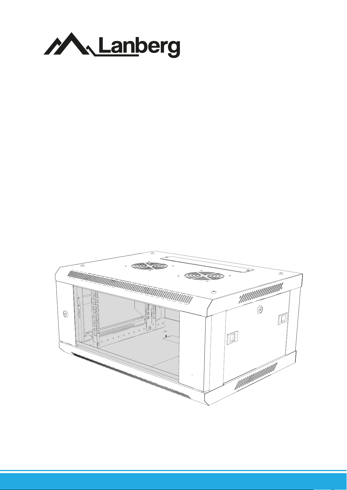
Szafy wiszące 19”
seria WF01 64/66 V2
19” Wall-mount cabinets
WF01 64/66 V2 series
Armarios de pared 19”
serie WF01 64/66 V2
Instrukcja obsługi
User’s manual
Manual de instrucciones
2021/05
Page 2

Spis treści
1. Ważne zalecenia wstępne i informacje dotyczące użytkowania szaf wiszących 19” szybko składanych .............................................................4
1.1 Wprowadzenie .......................................................................................................................................................................................................................................4
1.2 Zgodność z przepisami prawnymi i regulacjami dotyczącymi bezpieczeństwa i środowiska .................................................................................4
1.3 Zawartość opakowania .......................................................................................................................................................................................................................4
1.4 Ogólne wytyczne dotyczące bezpieczeństwa i środków ostrożności ...............................................................................................................................5
1.5 Wytyczne dotyczące zasad bezpieczeństwa ESD .....................................................................................................................................................................5
1.6 Transport ..................................................................................................................................................................................................................................................5
1.7 Gwarancja ................................................................................................................................................................................................................................................5
1.8 Rozpakowanie i kontrola ....................................................................................................................................................................................................................6
1.9 Przechowywanie i wentylacja ..........................................................................................................................................................................................................6
2. Montaż ......................................................................................................................................................................................................................................................6
2.1 Przygotowanie .......................................................................................................................................................................................................................................6
2.1.1. Zestawienie elementów .....................................................................................................................................................................................................................6
2.2 Składanie szafy wiszącej 19” serii WF01 V2 ..................................................................................................................................................................................7
2.2.1. Montaż zamka w drzwiach przednich ..........................................................................................................................................................................................7
2.2.2. Montaż zamka w drzwiach bocznych ...........................................................................................................................................................................................8
2.2.3. Montaż pionowych szyn montażowych .......................................................................................................................................................................................8
2.2.4. Montaż ram bocznych z pokrywą dolną i górną .......................................................................................................................................................................9
2.2.5. Montaż tylnej pokrywy ....................................................................................................................................................................................................................11
2.2.6. Montaż płaskich zaślepek ............................................................................................................................................................................................................... 11
3. Montaż szafy na ścianie ................................................................................................................................................................................................................... 12
4. Montaż drzwi bocznych .................................................................................................................................................................................................................. 13
5. Montaż drzwi przednich ................................................................................................................................................................................................................. 13
6. Montaż uziemienia ............................................................................................................................................................................................................................13
Table of contents
1. Important introductory recommendations and usage information of 19” wall-mount cabinets ........................................................................ 14
1.1 Introduction ......................................................................................................................................................................................................................................... 14
1.2 Compliance with legal and regulatory provisions regarding safety and the environment .................................................................................... 14
1.3 Packaging contents ...........................................................................................................................................................................................................................14
1.4 General safety precautions .............................................................................................................................................................................................................15
1.5 Guidelines for ESD security principles ........................................................................................................................................................................................15
1.6 Transport ............................................................................................................................................................................................................................................... 15
1.7 Warranty ................................................................................................................................................................................................................................................ 15
1.8 Unpacking and examination ......................................................................................................................................................................................................... 15
1.9 Storage and ventilation ................................................................................................................................................................................................................... 16
2. Assembly ...............................................................................................................................................................................................................................................16
2.1 Preparations ......................................................................................................................................................................................................................................... 16
2.1.1. Table of components ........................................................................................................................................................................................................................ 16
2.2 19” cabinet installation steps .........................................................................................................................................................................................................17
2.2.1. Front door lock installation ............................................................................................................................................................................................................ 17
2.2.2. Side door lock installation .............................................................................................................................................................................................................. 18
2.2.3. Vertical mounting rails installation .............................................................................................................................................................................................18
2.2.4. Installation of side frames with top and bottom cover ........................................................................................................................................................19
2.2.5. Rear cabinet cover installation ......................................................................................................................................................................................................21
2.2.6. Flat blank panels installation ......................................................................................................................................................................................................... 21
3. Cabinet wall installation .................................................................................................................................................................................................................. 22
4. Side door reinstallation ...................................................................................................................................................................................................................23
5. Front door installation .....................................................................................................................................................................................................................23
6. Grounding ............................................................................................................................................................................................................................................ 23
Lanberg © 2015-2021
Page 3

Índice
1. Recomendaciones previas importantes e información relativa al uso de los armarios de pared 19” de montaje rápido...........................24
1.1 Introducción ........................................................................................................................................................................................................................................ 24
1.2 Conformidad con las disposiciones legales y regulaciones relativas a la seguridad y el medio ambiente .....................................................24
1.3 Contenido del embalaje .................................................................................................................................................................................................................. 24
1.4 Indicaciones generales sobre seguridad y medidas de precaución ............................................................................................................................... 25
1.5 Indicaciones relativas a las normas de seguridad ESD .........................................................................................................................................................25
1.6 Transporte ............................................................................................................................................................................................................................................ 25
1.7 Garantía ................................................................................................................................................................................................................................................. 25
1.8 Desembalado y control ................................................................................................................................................................................................................... 25
1.9 Almacenamiento y ventilación ..................................................................................................................................................................................................... 26
2. Montaje ................................................................................................................................................................................................................................................. 26
2.1 Preparación .......................................................................................................................................................................................................................................... 26
2.1.1. Lista de elementos ............................................................................................................................................................................................................................ 26
2.2 Montaje del armario de pared 19” de la serie WF01 V2 .......................................................................................................................................................27
2.2.1. Montaje de la cerradura en la puerta delantera ..................................................................................................................................................................... 27
2.2.2. Montaje de la cerradura en las puertas laterales ....................................................................................................................................................................28
2.2.3. Montaje de los carriles de montaje verticales ......................................................................................................................................................................... 28
2.2.4. Montaje de los marcos laterales con la tapa inferior y superior .......................................................................................................................................29
2.2.5. Montaje de la tapa posterior ......................................................................................................................................................................................................... 31
2.2.6. Montaje de los tapones planos .....................................................................................................................................................................................................31
3. Montaje del armario en la pared .................................................................................................................................................................................................. 32
4. Montaje de las puertas laterales...................................................................................................................................................................................................33
5. Montaje de la puerta delantera .................................................................................................................................................................................................... 33
6. Montaje de la puesta a tierra ......................................................................................................................................................................................................... 33
Lanberg © 2015-2021
Page 4
1. Ważne zalecenia wstępne i informacje dotyczące użytkowania szaf wiszących 19” szybko składanych
1.1 Wprowadzenie
ZACHOWAJ TĘ INSTRUKCJĘ - Niniejszy zbiór zaleceń, wytycznych, zasad bezpieczeństwa zastrzeżeń oraz instrukcji obsługi szaf
wiszących 19” marki Lanberg, z wyszczególnieniem obsługiwanych poniższych modeli:
• WF01-6404-10B
• WF01-6404-10S
• WF01-6604-10B
• WF01-6604-10S
• WF01-6406-00B
• WF01-6406-00S
• WF01-6406-10B
• WF01-6406-10S
Zawiera również dane logistyczne, techniczne, instrukcje i przepisy, których należy przestrzegać oraz dostosować się do nich
podczas transportu, montażu, użytkowania i ewentualnego serwisowania produktów. Pod żadnym pozorem nie należy korzystać z
urządzenia przed uważnym przeczytaniem oraz pełnym dostosowaniem się do wszystkich informacji zawartych w instrukcji obsługi.
Zachowaj tę instrukcję do jej wykorzystania w późniejszych celach. Wszelkie zdjęcia, rysunki zawarte w instrukcji mają charakter
poglądowy. Informacje zawarte w niniejszej instrukcji obsługi zostały sprawdzone i są uważane za wystarczające. Dostawca nie ponosi
odpowiedzialności za wszelkie nieścisłości, które mogą być zawarte w tym dokumencie, ani nie zobowiązuje się do uaktualniania
lub zachowania bieżących informacji w tej instrukcji lub powiadamiania jej użytkowników bądź organizacji o jej aktualizacji.
W szczególności właściciele marki Lanberg nie ponoszą odpowiedzialność za jakikolwiek sprzęt, oprogramowanie lub dane
przechowywane lub używane wraz z produktem, w tym koszty naprawy, wymiany, integracja, instalacja lub odzyskiwanie sprzętu,
oprogramowania lub danych w przypadku niewłaściwego użycia produktu lub jego elementów.
Właściciele marki Lanberg zastrzegają sobie prawo do wprowadzania zmian w niniejszej instrukcji w dowolnym czasie i bez uprzedzenia.
Produkty o których mowa w niniejszej instrukcji, w tym dokumentacja, są własnością właścicieli marki Lanberg i ich licencjodawców.
Jakiekolwiek użycie lub reprodukcja tych produktów, włącznie z dokumentacją jest zabroniona, z wyjątkiem wyraźnego zezwolenia
na odpowiednich warunkach licencji.
UWAGA: W celu uzyskania najbardziej aktualnej wersji tej instrukcji, proszę odwiedzić naszą witrynę internetową pod adresem
www.lanberg.pl.
• WF01-6606-00B
• WF01-6606-00S
• WF01-6606-10B
• WF01-6606-10S
• WF01-6409-00B
• WF01-6409-00S
• WF01-6409-10B
• WF01-6409-10S
• WF01-6609-00B
• WF01-6609-00S
• WF01-6609-10B
• WF01-6609-10S
• WF01-6412-00B
• WF01-6412-00S
• WF01-6412-10B
• WF01-6412-10S
• WF01-6612-00B
• WF01-6612-00S
• WF01-6612-10B
• WF01-6612-10S
• WF01-6415-10B
• WF01-6415-10S
• WF01-6615-10B
• WF01-6615-10S
• WF01-6418-10B
• WF01-6418-10S
• WF01-6618-10B
• WF01-6618-10S
• WF01-6422-10B
• WF01-6422-10S
• WF01-6622-10B
• WF01-6622-10S
• WF01-6427-10B
• WF01-6427-10S
• WF01-6627-10B
• WF01-6627-10S
1.2 Zgodność z przepisami prawnymi i regulacjami dotyczącymi bezpieczeństwa i środowiska
Ten produkt jest zgodny z przepisami Unii Europejskiej (UE) dotyczącymi bezpieczeństwa i środowiska.
Wymienione w poniższej instrukcji wyroby zostały dopuszczone do obrotu na terenie UE uzyskując deklarację zgodności Unii
Europejskiej, która zawiera deklarację z zasadniczymi wymaganiami oraz innymi stosownymi postanowieniami poniższych dyrektyw
oraz, że zastosowano niżej wymienione normy zharmonizowane.
Dyrektywa: RoHS 2011/65/UE + 2015/863/UE
Normy: IEC 62321-4:2013 + A1:2017; IEC 62321-5:2013;
IEC 62321-6:2015; IEC 62321-7-1:2015; IEC 62321-7-2:2017; IEC 62321-8:2017;
Wraz z rozwojem produktów i aktualizacjami przepisów dotyczącymi CE, deklaracja może ulegać zmianie. Najnowsza deklaracja
zgodności (CE) znajduje się na stronie: www.lanberg.pl.
UWAGA: Użycie symbolu WEEE (przekreślony kosz) oznacza, że niniejsze wyroby nie mogą być traktowane jako odpad domowy.
Prawidłowa utylizacja zużytego sprzętu pozwala uniknąć zagrożeń dla zdrowia ludzi i środowiska naturalnego, wynikających
z możliwej obecności w sprzęcie niebezpiecznych substancji, mieszanin oraz części składowych, a także niewłaściwego składowania
i przetwarzania takiego sprzętu. Zbiórka selektywna pozwala także na odzyskiwanie materiałów i komponentów, z których
wyprodukowane było urządzenie. W celu uzyskania szczegółowych informacji dotyczących recyklingu niniejszych produktów należy
skontaktować się z punktem sprzedaży detalicznej, w którym dokonano zakupu, lub organem władzy lokalnej.
1.3 Zawartość opakowania
W opakowaniu transportowym powinny być dostarczone następujące przedmioty:
• (1x) Drzwi przednie wyposażone w 2 bolce uziemiające.
• (2x) Rama boczna szafy z zamocowanymi drzwiami, wyposażonymi w 2 zaczepy.
• (1x) Pokrywa górna z przepustem kablowym oraz 2 otworami po środku na wentylatory 12x12 cm.
• (2x) Płaska zaślepka do górnego oraz dolnego przepustu kablowego.
• (1x) Pokrywa tylna szafy.
• (4x) Ponumerowane pionowe szyny montażowe do montażu urządzeń w standardzie RACK.
• (1x) Listwa do montażu ściennego.
• Niezbędne akcesoria do montażu w woreczku stronowym: (16x) śruby krzyżakowe M4*8 samogwintujące; (8x) śruby krzyżakowe
M5*8 samogwintujące; (8x) śruby krzyżakowe M6*12; (1x) plastikowa podkładka; (1x) zestaw uziemiający (przewód, podkładki,
nakrętki); (1x) zamek drzwi przednich z brelokiem podwójnych kluczy oraz płaskim metalowym językiem; (2x) zamek drzwi
bocznych z brelokiem podwójnych kluczy oraz wygiętym metalowym językiem; (12x dla rozmiaru < 12 U; 24x dla rozmiaru >= 12
U) śruby krzyżakowe M6*12 zkoszyczkami M6; (1x) papierowa instrukcja.
• (1x) Pokrywa dolna z przepustem kablowym i 4 otworami z gwintowaną nakrętką M10 po bokach oraz 2 bolcami uziemiającymi.
4
Lanberg © 2015-2021
PL
Page 5

1.4 Ogólne wytyczne dotyczące bezpieczeństwa i środków ostrożności
• Bezwzględnie należy przestrzegać specykacji urządzenia przy posługiwaniu się nim oraz przy podłączaniu go do jakichkolwiek
wyrobów zewnętrznych. Należy również tak samo przestrzegać specykacji tych wyrobów zewnętrznych, do których niniejsze
urządzenie ma zostać podłączone.
• Nie wolno używać produktu do pracy poza znamionowymi wartościami podanymi w jego specykacji. Jakiekolwiek uszkodzenia
spowodowane przez odstępstwo od tych wartości w trakcie posługiwania się urządzeniem nie podlegają gwarancji.
• Wszelka instalacja, połączenia, okablowania oraz obwody w których będzie użytkowany produkt muszą być wykonane w sposób
zgodny z lokalnie obowiązującymi przepisami dotyczącymi elektryczności oraz w taki sposób, aby wyeliminować ryzyko nadepnięcia
lub potknięcia się o nie. Używaj kabli zasilających tylko z certykatem VDE oraz CE przy ich podłączaniu do urządzenia. Konieczne
jest stosowanie tych samych procedur wymienionych w tym punkcie przy podłączaniu okablowania do wyrobu lub jego samego do
elementów zewnętrznych.
• W przypadku zewnętrznych urządzeń podłączanych do niniejszego wyrobu należy kategorycznie przestrzegać instrukcji obsługi
dostarczonych przez ich producenta.
• W celu zapewnienia bezpieczeństwa oraz zgodności, należy używać wyłącznie komponentów zgodnych z specykacją lub częściami
zalecanymi przez producenta.
• Podczas trwania gwarancji zabrania się wymiany jakichkolwiek elementów produktu przez jego użytkowników. Serwisowanie
powierzaj tylko i wyłącznie wykwalikowanemu personelowi technicznemu, takiemu jak np. serwis producenta lub autoryzowanego
importera.
• W przypadku konieczności wymogu serwisowania urządzenia, powinno się ono odbywać lub być nadzorowane przez osobę
posiadającą odpowiednie kwalikacje do pracy z nim oraz wiedzę dotyczącą zachowania właściwych środków ostrożności. Wszystko
to zgodnie i w myśl lokalnie obowiązujących przepisów.
• W przypadku konieczności wymogu serwisowania urządzenia lub innych czynności, które wymagać będą pracy wewnątrz urządzenia
lub kontaktu z elementami, które mogą być pod potencjalnym napięciem, należy przed dokonaniem tych czynności przestrzegać
następujących zasad bezpieczeństwa: zdjąć wszelkie bransoletki, naszyjniki, pierścionki, zegarki lub inne metalowe przedmioty z rąk
oraz szyi oraz używać narzędzi z izolowanymi uchwytami.
• Zawsze przed przystąpieniem do serwisowania urządzenia powinna znajdować się w pobliżu osoba, która zareagowałaby oraz
podjęła odpowiednie czynności w celu pomocy osobie serwisującej w razie wypadku. Osoba serwisująca powinna zawsze umyć ręce
po zakończeniu pracy z urządzeniem.
• NIGDY nie dopuszczaj do sytuacji, w której mogłyby wystąpić jakiekolwiek iskry lub płomienie w pobliżu urządzenia. Wystąpienie
takiej sytuacji może mieć bardzo negatywne konsekwencje w stosunku do osób oraz rzeczy znajdujących się w pobliżu.
• W przypadku pożaru natychmiastowo i (możliwie) bez zbędnej zwłoki odłącz dopływ zasilania sieciowego oraz zawiadom straż
pożarną o zaistniałej sytuacji, dzwoniąc pod numer straży obowiązujący w kraju, w którym przebywasz.
• Produkt przeznaczony jest do użytku wewnętrznego. Nie należy jakkolwiek pr zebudowywać i/lub modykować samego produktu i/lub
jego składowych.
• Do urządzenia pod żadnym pozorem nie wolno wprowadzać wyrobów, które nie są przeznaczone do tego celu.
• Producent i dystrybutor nie odpowiadają za jakiekolwiek szkody powstałe w wyniku niewłaściwego użytkowania i niewłaściwego
postępowania z wyrobem (niezgodnego z niniejszą instrukcją).
• Przed podjęciem czynności z wiązanych z zamocowaniem lub odłączeniem urządzenia, podpięciem lub odłączeniem kabli do niego, wszae
wiszącej 19” serii, najpierw podłącz jego wszystkie elementy do zwerykowanego i sprawnie działającego uziemienia.
• Upewnij się, że wszystkie elementy przymocowane od nowości w szae wiszącej 19” serii, jak i sprzęty zamocowane przez użytkownika są
prawidłowo przykręcone lub odkręcone gdy wykonywany jest demontaż. Niedopuszczalna jest sytuacja, w której jakiekolwiek elementy
produktu lub stanowiące jego spójność nie są odpowiednio zamocowane / zastosowane lub stwarzają zagrożenie przez błędną ich izolację
od pozostałych, funkcjonujących elementów, które w zetknięciu spowodowałyby zagrożenie.
1.5 Wytyczne dotyczące zasad bezpieczeństwa ESD
W celu zapobiegania uszkodzeniom wyrobu, systemu lub podzespołów elektrycznych przez wyładowanie elektrostatyczne (ESD), ważne
jest, aby podczas pracy z nimi odpowiednio przygotować się oraz ostrożnie je obsługiwać. Następujące środki są ogólnie wystarczające,
aby chronić wyrób przed wystąpieniem ESD:
• Nie używaj metalowych pasków na rękach, aby zapobiec wyładowaniom statycznym.
• Dotknij najpierw uziemionego, metalowego przedmiotu przed przystąpieniem do pracy.
• Podczas obsługi urządzeń elektrycznych należy unikać kontaktu z pinami, wtyczkami i jakimikolwiek przekaźnikami energii.
• Podczas przemieszczania elementów elektronicznych zaleca się chwytanie tylko za ich (odizolowane) krawędzie, gdzie nie występuje
jakikolwiek przepływ prądu. Nie dotykaj podzespołów, układów scalonych, modułów pamięci, styków etc.
• Wszelkie elektroniczne urządzenia włóż z powrotem do antystatycznych toreb (o ile to możliwe) gdy nie są one używane.
1.6 Transport
Podczas transportu należy przechowywać produkt tylko i wyłącznie w oryginalnym opakowaniu w celu ochrony przed wstrząsami oraz
uderzeniami. Nie należy wyrzucać opakowania do śmieci. W przypadku wysyłki produktu na gwarancję, kategorycznie należy użyć
oryginalnego kartonu.
1.7 Gwarancja
Gwarancja nie przysługuje w przypadku wystąpienia awarii i wad wynikających z niewłaściwego użytkowania i postępowania
z urządzeniem (niezgodnego z niniejszą instrukcją). Uszkodzenia mechaniczne są podstawą do odrzucenia reklamacji. W celu złożenia
gwarancji lub rękojmi, skontaktuj się z swoim sprzedawcą.
PL
Lanberg © 2015-2021
5
Page 6
1.8 Rozpakowanie i kontrola
W obecności przewoźnika ostrożnie rozpakuj produkt z kartonu transportowego oraz koniecznie sprawdź czy:
• Zawartość opakowania zawiera elementy wymienione w pkt. 1.3.
• Wszystkie elementy są nieuszkodzone.
W przypadku braku, uszkodzenia, nieścisłości co do elementów wymienionych w pkt. 1.3, należy spisać protokół uszkodzenia
(wprzypadku ich występowania) oraz koniecznie zgłosić sprawę do sprzedawcy. Wymagane są: zdjęcia, numer partii oraz opis problemu.
Wskazane czynności należy wykonać w tym samym dniu co data dostawy produktu.
1.9 Przechowywanie i wentylacja
• Produkt powinien być instalowany tylko w lokalizacji z ograniczonym dostępem (wydzielone pomieszczenia na sprzęt etc.).
• Nie należy instalować i przechowywać go w miejscach, w których obecna jest stojąca albo bieżąca woda, wilgotność lub jakiekolwiek
inne płynne substancje.
• Należy pamiętać, aby unikać wystawiania urządzenia na bezpośrednie działanie promieni słonecznych.
• Umieść urządzenie na stabilnej, suchej powierzchni w dobrze wentylowanym miejscu. Pozostaw co najmniej 100 mm wolnej
przestrzeni wokół niego, aby zapewnić odpowiednią wentylację.
• Urządzenie przeznaczone jest do pracy tylko i wyłącznie w kontrolowanym środowisku (kontrolowana temperatura oraz wilgotność
otoczenia zgodnie z informacjami zawartymi w specykacji, praca wewnątrz budynku, bez zanieczyszczeń przewodzących [zapylenia,
palnych gazów, substancji powodujących korozje etc.]).
2. Montaż
Należy ściśle przestrzegać zaleceń zawartych w tej instrukcji.
i
2.1 Przygotowanie
Przygotuj odpowiednią ilość miejsca na podłożu na którym odbędzie się montaż. Ostrożnie wyjmij wszystkie elementy z kartonu
transportowego. Dalsze instrukcje montażu będą opierać się o zawarty schemat. Przygotuj również (własne) 4 kołki rozporowe oraz
4 śruby dopasowane nośnością do zakładanej całościowej wagi szafy oraz średnicą do otworów listwy do montażu ściennego, która
wynosi: 4 – Ø 10.
Ze względu na użycie śrub krzyżakowych M6*12 do przymocowania pokrywy górnej oraz dolnej z ramami bocznymi zalecamy
przygotowanie dobrego śrubokręta krzyżakowego. Zalecana specykacja to PH3x150 mm.
2.1.1. Zestawienie elementów
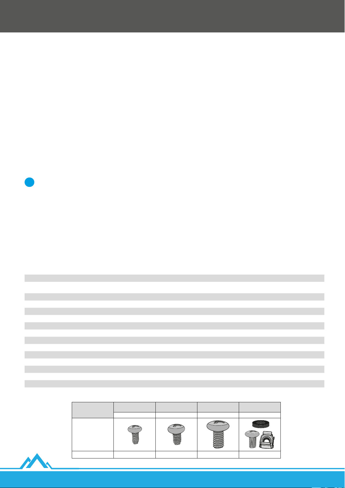
Komponent Dostarczona ilość Oznaczenie
Przeszklone / metalowe drzwi przednie wyposażone w 2 bolce uziemiające 1x A
Rama boczna szafy z zamocowanymi drzwiami wyposażonymi w 2 zaczepy 2x
Pokrywa górna z przepustem kablowym oraz 2 otworami po środku na wentylatory 12x12 cm 1x D
Płaska zaślepka do górnego oraz dolnego przepustu kablowego 2x E
Pokrywa tylna szafy 1x F
Ponumerowane pionowe szyny montażowe 4x G
Listwa do montażu ściennego 1x H
Śruba krzyżakowa samogwintująca M4*8 16x I
Śruba krzyżakowa samogwintująca M5*8 8x J
Śruba krzyżakowa M6*12 8x K
Śruba krzyżakowa M6*12 z koszyczkami M6 < 10 U: 12x >= 10U: 24x L
Plastikowa podkładka pod drzwi przednie 1x N
Zestaw uziemiający (przewód, podkładki, nakrętki) 1x M
Zamek drzwi przednich z brelokiem podwójnych kluczy oraz płaskim metalowym językiem 1x O
Zamek drzwi bocznych z brelokiem podwójnych kluczy oraz wygiętym metalowym językiem 2x P
Pokrywa dolna z przepustem kablowym i 4 otworami z gwintowaną nakrętką M10 po bokach oraz 2 bolcami uziemiającymi 1x R
B
C
Śruba krzyżakowa
Element
Rysunek
Dostarczona ilość 16x 8x 8x < 10 U: 12x >= 10U: 24x
6
samogwintująca M4*8
I J K L
Lanberg © 2015-2021
Śruba krzyżakowa
samogwintująca M5*8
Śruba krzyżakowa M6*12
Śruba krzyżakowa M6*12
z koszyczkami M6
PL
Page 7
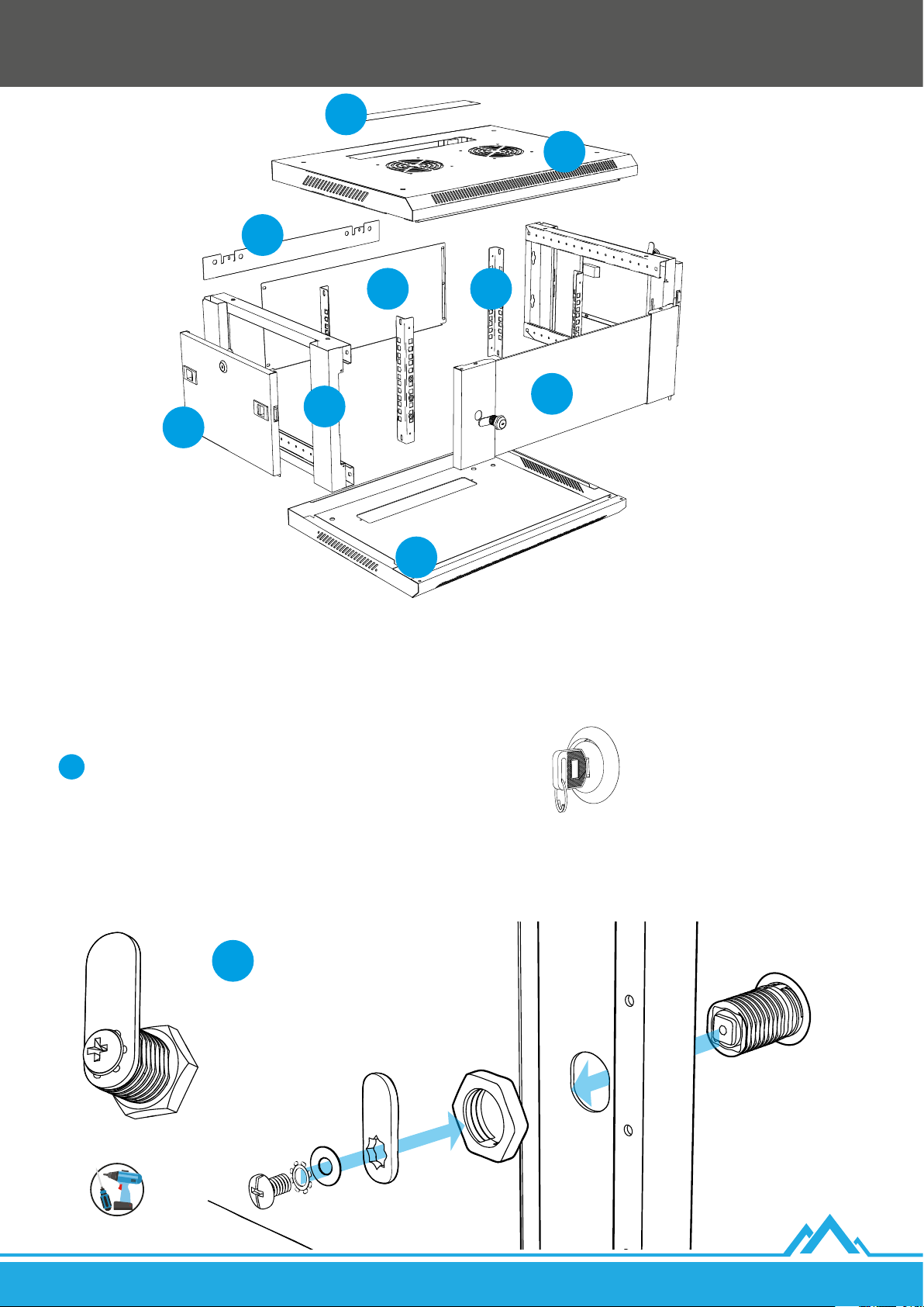
H
E
D
F G
B/C
A
B/C
R
2.2 Składanie szafy wiszącej 19” serii WF01 V2
2.2.1. Montaż zamka w drzwiach przednich
1. Wprowadź moduł zamka z woreczka strunowego oznaczonego elementem [O] przez drzwi tak, aby 2 równoległe płaskie
części modułu znajdowały się w pozycji poziomej. Następne kroki będą dotyczyły elementów znajdujących się w tym woreczku.
Ustaw otwór modułu zamka za pomocą kluczyków w pozycji pionowej.
i
2. Przykręć nakrętkę wprowadzając ją stroną z wygrawerowanymi trójkątami w stronę drzwi na moduł zamka. Na samym końcu
przytrzymaj moduł zamka za pomocą kluczyków i postaraj się dobrze dokręcić nakrętkę.
3. Nanieś płaski metalowy język zamka w pionie (skierowany: ku górze - gdy drzwi są ukierunkowane stroną jak na poniższym rysunku
lub w przeciwnym razie ku dołowi) na kwadratowy element modułu z otworem na śrubę. Kolejno nanieś płaską metalową okrągłą
podkładkę, a następnie jej gwieździstą formę. Całość przymocuj wkręcając śrubę do modułu zamka.
PL
O
Lanberg © 2015-2021
7
Page 8
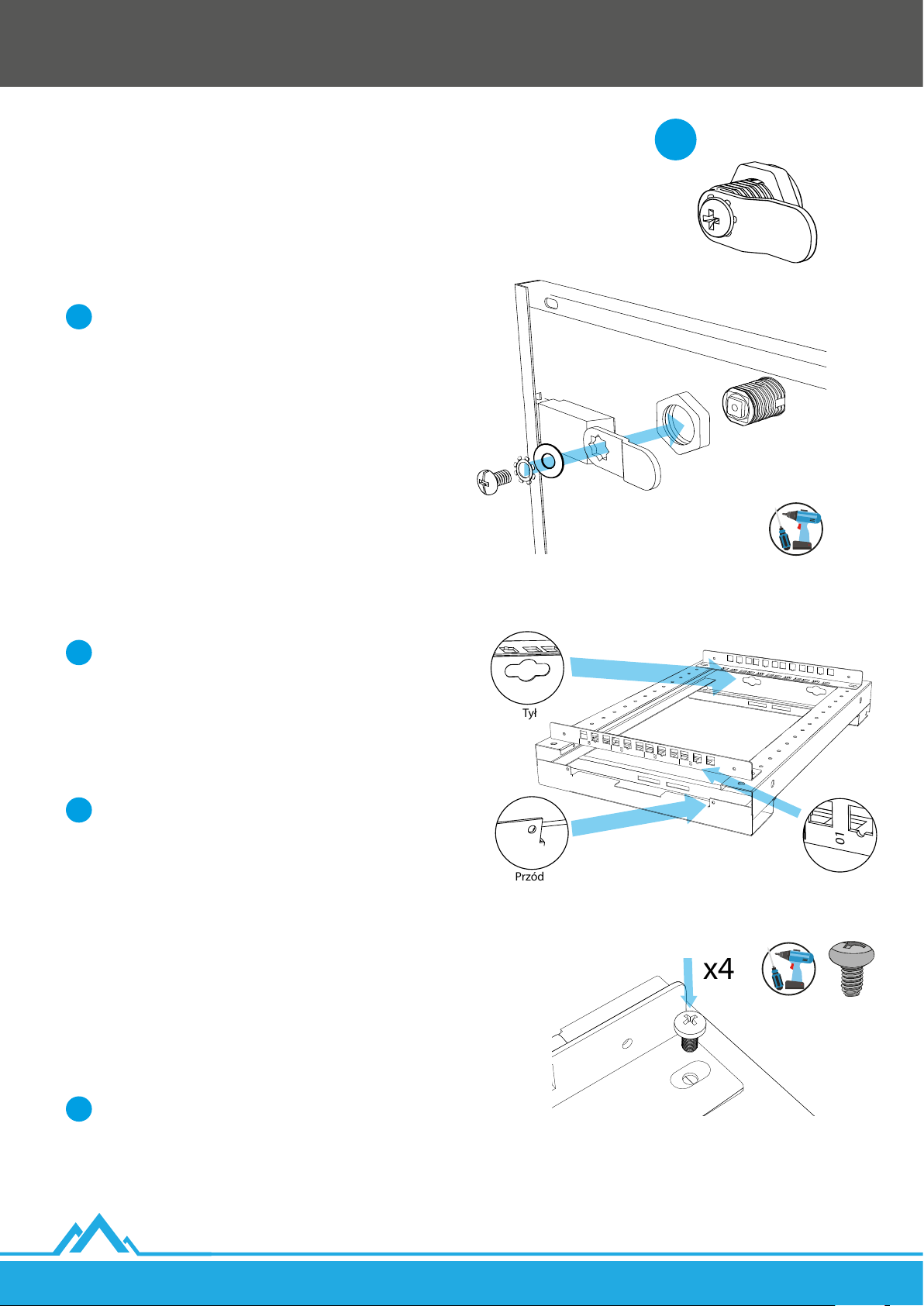
2.2.2. Montaż zamka w drzwiach bocznych
01
02
03
04
Tył
Przód
01
02
03
04
01
x4
1. Wyjmij drzwi boczne z ram bocznych [B + C]. Ich ponowny
montaż przebiegnie na końcowym etapie składania szafy.
2. Wprowadź moduł zamka z woreczka strunowego oznaczonego
elementem [P] przez drzwi tak , aby 2 równoległe płaskie części
modułu znajdowały się w pozycji poziomej. Następne kroki
będą dotyczyły elementów znajdujących się w tym woreczku.
Ustaw otwór modułu zamka za pomocą kluczyków
i
wpozycji poziomej.
3. Przykręć nakrętkę wprowadzając ją stroną z wygrawerowanymi
trójkątami w stronę drzwi na moduł zamka. Na samym końcu
przytrzymaj moduł zamka za pomocą kluczyków i postaraj się
dobrze dokręcić nakrętkę.
4. Nanieś wygięty metalowy język zamka w poziomie (wygiętą
częścią skierowaną bliżej drzwi) na kwadratowy element
modułu z otworem na śrubę. Kolejno nanieś płaską metalową
okrągłą podkładkę, a następnie jej gwieździstą formę. Całość
przymocuj wkręcając śrubę do modułu zamka.
5. Analogiczne kroki 1 ~ 4 wykonaj dla drugich drzwi
bocznych [C].
P
2.2.3. Montaż pionowych szyn montażowych
Przed dalszym montażem zwróć uwagę, gdzie znajduje się
i
przednia i tylna strona ram bocznych [B + C].
Odległość między środkami małych otworów znajdujących
się na ramach bocznych [B + C] wynosi 25 mm.
Maksymalny dystans (głębokość robocza) między
przednimi i tylnymi pionowymi szynami montażowymi
(zuwzględnieniem ich grubości) wynosi:
I) Dla szaf wiszących o całkowitej długości 450 mm: 379.5 mm.
i
II) Dla szaf wiszących o całkowitej długości 600 mm: 529.5 mm.
Zaleca się jednak montaż tylnych pionowych szyn
montażowych na 3-cich od końca otworach znajdujących
się na ramach bocznych (różnica 50 mm), aby zmieścić
urządzenia wraz z wtyczką z kablem (średnio ok. 55 mm).
1. Połóż płasko dwie ramy boczne [B + C] (bez zamontowanych
drzwi) tak, aby były skierowane przednią stroną
wtwoim kierunku.
2. Użyj 2 ponumerowanych pionowych szyn montażowych [G]
oraz dobierz wymaganą odległość między nimi na lewej ramie
bocznej [B].
8
Zwróć koniecznie uwagę na to, aby numeracja przednich
i
pionowych szyn przebiegała rosnąco od prawej do lewej
(spoglądając na przedstawione rysunki) i analogicznie
dlatylnych.
3. Użyj łącznie 4 śrub krzyżakowych samogwintujących M5*8 [J],
aby zamocować pionowe szyny montażowe do ramy bocznej
- po 2 na każdy koniec szyny.
Lanberg © 2015-2021
PL
Page 9
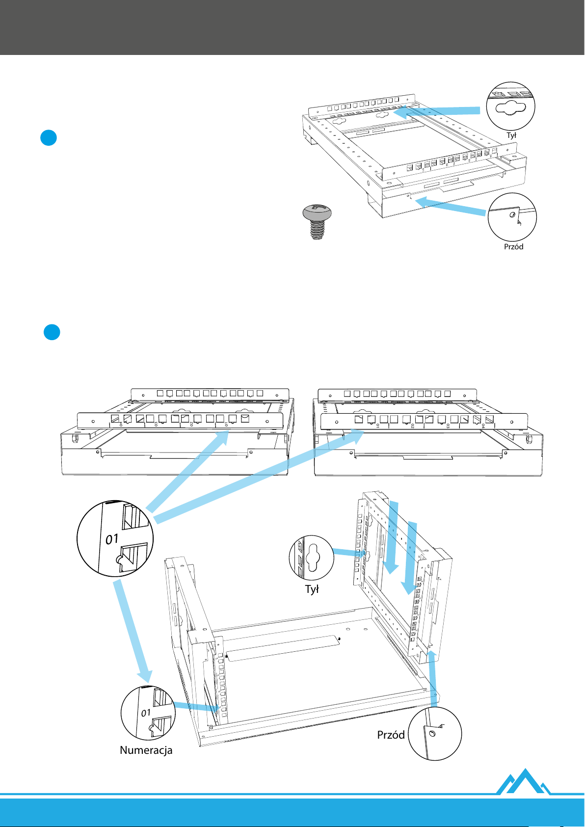
4. Użyj 2 ponumerowanych pionowych szyn montażowych [G]
01
02
03
04
Tył
Przód
01
02
03
04
01
02
03
04
Tył
Przód
Numeracja
01
02
03
04
01
02
03
04
01
02
03
04
01
02
03
04
oraz dobierz taką samą odległość jak w pkt. 2 na prawej ramie
bocznej [C].
Zwróć koniecznie uwagę na to, aby numeracja przednich
i
pionowych szyn przebiegała rosnąco od lewej do prawej
(spoglądając na przedstawione rysunki) i analogicznie
dlatylnych.
5. Użyj łącznie 4 śrub krzyżakowych samogwintujących M5*8[J],
aby zamocować pionowe szyny montażowe do ramy bocznej
- po 2 na każdy koniec szyny.
2.2.4. Montaż ram bocznych z pokrywą dolną i górną
1. Przygotuj pokrywę dolną [R] w taki sposób, aby przepust kablowy znajdował się z tyłu.
2. Lewą ramę boczną [B] umieść po lewej stronie pokrywy dolnej, a prawą ramę boczną [C] po prawej stronie pokrywy.
Przed podjęciem kolejnego etapu montażu upewnij się, czy:
i
I) Numeracja przebiega rosnąco od pokrywy dolnej do górnej na przednich jak itylnych pionowych szynachmontażowych.
II) Pary przeciwległych szyn są zamontowane na tych samych długościach.
PL
Lanberg © 2015-2021
9
Page 10
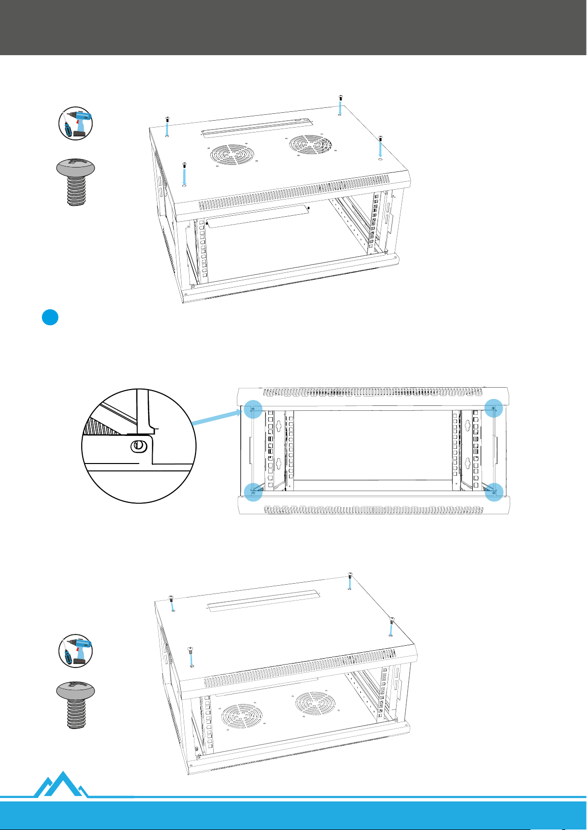
3. Nałóż pokrywę górną [D] przepustem kablowym znajdującym się z tyłu na ramy boczne [B + C] oraz dopasuj ją do ich konstrukcji.
4. Użyj łącznie 4 śruby krzyżakowe M6*12 [K], aby zamocować pokrywę górną do ram bocznych - po 2 na każdy bok.
Pamiętaj, aby:
i
I) Systematycznie zwracać uwagę na dopasowanie pokrywy górnej [D] z otworami na ramach bocznych [B + C]. Nie dokręcaj każdej
śruby 100%! Najpierw wprowadź wszystkie na 2/3 wysokości, sprawdź spasowanie, a następnie dokręć wszystkie.
II) Zwrócić również uwagę czy małe otwory na śruby M4*8 [I] znajdujące się na przedniej stronie obu pokryw, jak i ram bocznych,
pokrywają się ze sobą.
5. Obróć o 180 stopni całą konstrukcję. Dopasuj pokrywę dolną [R] do konstrukcji ram bocznych.
6. Użyj łącznie 4 śruby krzyżakowe M6*12 [K], aby zamocować pokrywę dolną do ram bocznych - po 2 na każdy bok.
10
Lanberg © 2015-2021
PL
Page 11
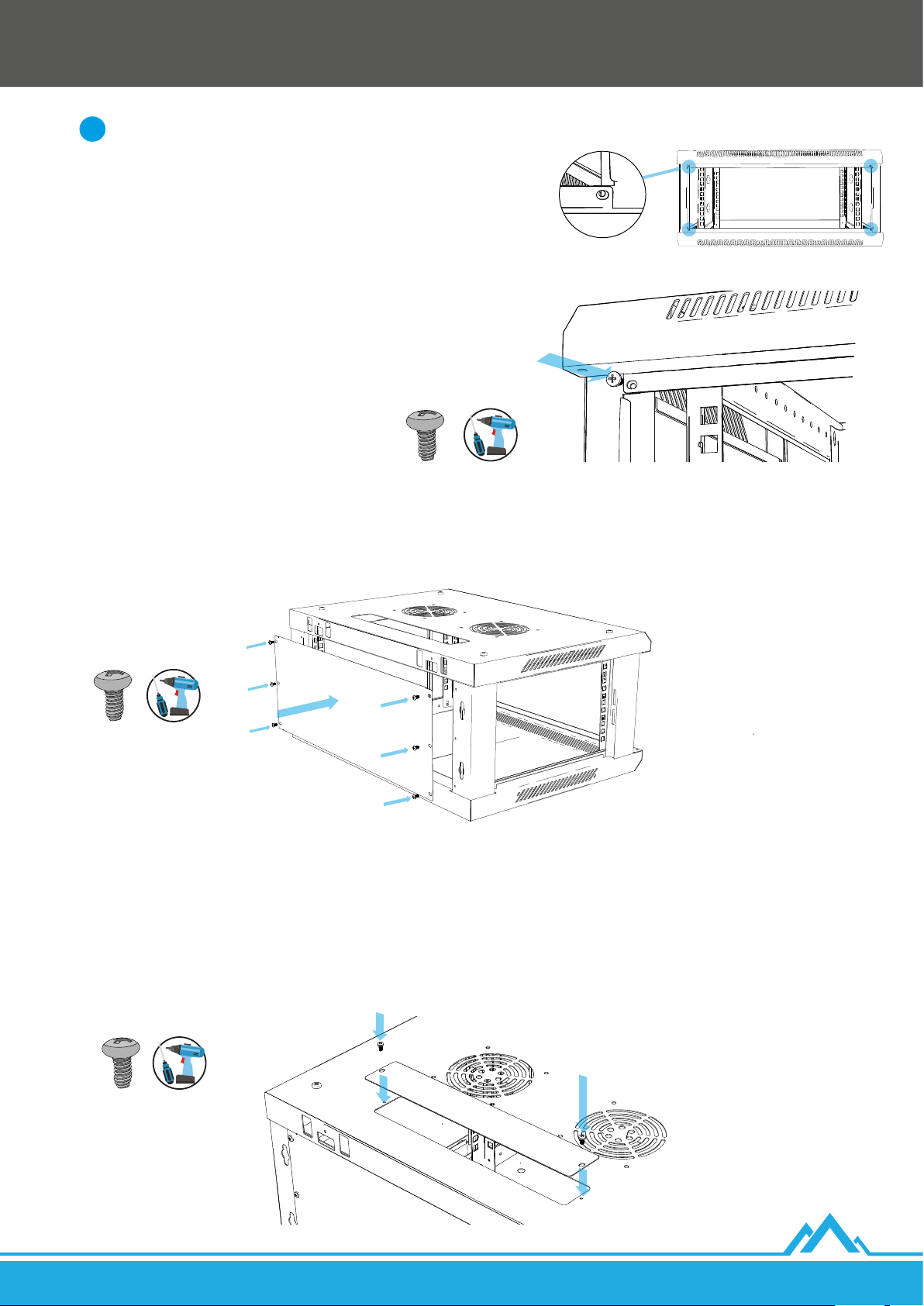
Pamiętaj, aby:
i
I) Systematycznie zwracać uwagę na dopasowanie pokrywy dolnej [R]
zotworami na ramach bocznych [B + C]. Nie dokręcaj każdej śruby 100%!
Najpierw wprowadź wszystkie na 2/3 wysokości, sprawdź spasowanie,
anastępnie dokręć wszystkie.
II) Zwrócić również uwagę czy małe otwory na śruby M4*8 [I]
znajdujące się na przedniej stronie obu pokryw, jak i ram bocznych,
pokrywająsięzesobą.
7. Użyj łącznie 4 śrub krzyżakowych samogwintujących M4*8 [I], aby
przymocować z przedniej strony obie pokrywy [D + P] z ramami
bocznymi [B + C] - po 1 na każdy bok.
2.2.5. Montaż tylnej pokrywy
1. Dopasuj pokrywę tylną [F] tak, aby jej 6 otworów pokrywało się z 6 otworami znajdującymi się z tyłu ram bocznych [B + C].
2. Użyj łącznie 6 śrub krzyżakowych M4*8 [I], aby zamocować pokrywę tylną do ram bocznych - po 3 na stronę.
2.2.6. Montaż płaskich zaślepek
1. Dopasuj płaską zaślepkę [E] do dolnego przepustu kablowego pokrywy tak, aby otwory na śruby na obu elementach pokrywały się.
2. Użyj łącznie 2 śrub krzyżakowych M4*8 [I], aby zamocować zaślepkę do dolnego przepustu - po 1 na stronę.
3. Obróć konstrukcję szafy o 180 stopni.
4. Dopasuj kolejną płaską zaślepkę [E] do górnego przepustu kablowego pokrywy tak, aby otwory na śruby na obu elementach
pokrywały się.
5. Użyj kolejnych 2 śrub krzyżakowych M4*8 [I], aby zamocować zaślepkę do górnego przepustu - po 1 na stronę.
PL
Lanberg © 2015-2021
11
Page 12
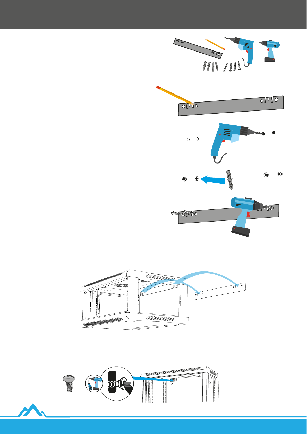
3. Montaż szafy na ścianie
1. Przygotuj (własne) 4 kołki rozporowe oraz 4 śruby
dopasowane nośnością do zakładanej całościowej wagi szafy
oraz średnicą do otworów listwy do montażu ściennego,
która wynosi: 4 – Ø 10. Odległość między środkami większych
otworów znajdujących się na listwie na daną stronę wynosi
69 mm, a między środkami większych otworów znajdujących
się na krańcach listwy (lewy i prawy) wynosi 468 mm.
2. Dopasuj listwę do montażu ściennego [H] do powierzchni
ściany i wyrównaj poziom.
3. Obrysuj 4 krawędzie otworów listwy (bez uwzględniania tych
na zaczepach).
4. Nawierć 4 otwory w miejsca obrysów, a następnie wprowadź
kołki rozporowe.
5. Ponownie dopasuj listwę tak, aby między jej 2 zaczepami
(w kształcie litery „L”) a ścianą było miejsce na
powieszenie szafy.
6. Wkręć 4 śruby w kołki rozporowe. Najpierw w 2 zewnętrzne
otwory (po 1 na bok), a następnie w 2 wewnętrzne.
7. Powieś złożoną szafę zaczepiając jej 2 otwory umieszczone ztyłu na górze pokrywy górnej [D] o 2 zaczepy listwy.
8. Za pomocą 2 śrub krzyżakowych samogwintujących M4*8 [I] przytwierdź tylną konstrukcję szafy z 2 zaczepami znajdującymi się na
listwie do montażu ściennego.
12
Lanberg © 2015-2021
PL
Page 13
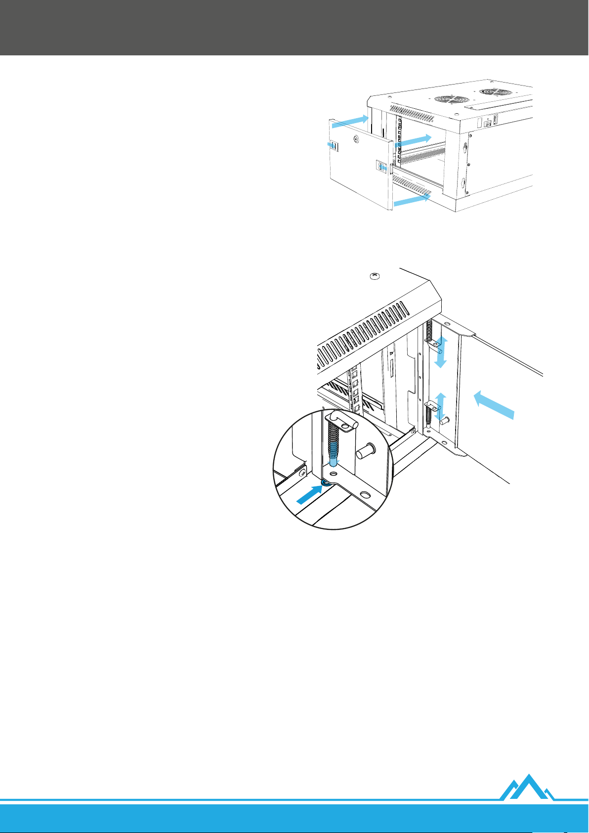
4. Montaż drzwi bocznych
1. Drzwi boczne, które należało na wcześniejszym etapie montażu
wyjąć, z powrotem zamontuj do ram bocznych [B + C] naciskając
równocześnie do środka 2 zaczepy, a w momencie gdy znajdą się na
równi z otworami ram zwolnij nacisk.
2. Wykorzystując klucze [P] zamknij drzwi ram bocznych.
5. Montaż drzwi przednich
1. Na jeden z dolnych otworów dolnej pokrywy [R] na który
planujesz osadzić bolec drzwi przednich [A] nanieś plastikową
podkładkę [N].
2. Osadź dolny bolec drzwi przednich [A] w dolnym otworze przez
plastikową podkładkę, a następnie wprowadź górny bolec w
otwór znajdujący się na górnej pokrywie [D] naciskając do środka
zawiasy (w kształcie litery L). W momencie gdy znajdzie się na
równi z otworem zwolnij nacisk.
3. Wykorzystując klucze [O] zamknij drzwi przednie.
6. Montaż uziemienia
W szae umieszczono 4 bolce uziemiające o średnicy 6 mm:
• 2x na drzwiach przednich [A].
• 2x na dolnej pokrywie [R].
W zestawie dołączono przewód uziemiający [M]. Składa się on z42 żył wykonanych z czystej miedzi (100% CU), po 0.16 mm każda. Przekrój
kabli wynosi ~0.9 mm
W celu połączenia jednego z głównych bolców uziemiających szafy (znajdujących się na dolnej pokrywie) z przyłączem wyrównawczym
należy zakupić osobno kabel o odpowiedniej długości, gdzie jego AWG powinno się mieścić w przedziale 17 ~ 18, a żyły powinny być
wykonane tylko z czystej miedzi (100% CU).
PL
2
. Kabel służy do połączenia dolnej pokrywy z drzwiami przednimi (z możliwością otwarcia ich w kącie do 180°).
Lanberg © 2015-2021
13
Page 14
1. Important introductory recommendations and usage information of 19” wall-mount cabinets
1.1 Introduction
PLEASE SAVE THIS MANUAL - it contains a set of recommendations, guidelines, safety rules, restrictions and operating instructions of
Lanberg’s 19” wall-mount cabinets, detailing the models supported below:
• WF01-6404-10B
• WF01-6404-10S
• WF01-6604-10B
• WF01-6604-10S
• WF01-6406-00B
• WF01-6406-00S
• WF01-6406-10B
• WF01-6406-10S
Manual also contains logistic and technical data, instructions, and regulations that must be observed and complied with during
transport, assembly, use, and potential maintenance of the products. Under no circumstances should you use the device before
carefully reading and fully adapting to all information in the user’s manual. Keep this manual for future reference. All photos, illustrations
contained in the instructions are for reference only. The information contained in this manual has been veried and is considered
sucient. The supplier is not responsible for any inaccuracies that may be included in this document, nor is he responsible for updating
or keeping the current information in this manual, nor for notifying its users or organization about the updates. In particular, Lanberg
owners are not responsible for any equipment, software, or data stored/used with the product, including maintenance, replacement,
integration, installation, or recovery of hardware, software, or data in the event of misuse of the product or its components.
Lanberg brand owners reserve the right to make changes to this manual at any time without notice. The products mentioned in this
manual, including the documentation, are the property of the Lanberg brand owners and its licensors. Any use or reproduction of
these products, including documentation, is prohibited, except as expressly authorized under the appropriate license terms.
NOTE: For the most up-to-date version of this manual, please visit our website at www.lanberg.eu.
• WF01-6606-00B
• WF01-6606-00S
• WF01-6606-10B
• WF01-6606-10S
• WF01-6409-00B
• WF01-6409-00S
• WF01-6409-10B
• WF01-6409-10S
• WF01-6609-00B
• WF01-6609-00S
• WF01-6609-10B
• WF01-6609-10S
• WF01-6412-00B
• WF01-6412-00S
• WF01-6412-10B
• WF01-6412-10S
• WF01-6612-00B
• WF01-6612-00S
• WF01-6612-10B
• WF01-6612-10S
• WF01-6415-10B
• WF01-6415-10S
• WF01-6615-10B
• WF01-6615-10S
• WF01-6418-10B
• WF01-6418-10S
• WF01-6618-10B
• WF01-6618-10S
• WF01-6422-10B
• WF01-6422-10S
• WF01-6622-10B
• WF01-6622-10S
• WF01-6427-10B
• WF01-6427-10S
• WF01-6627-10B
• WF01-6627-10S
1.2 Compliance with legal and regulatory provisions regarding safety and the environment
This product complies with EU safety and environmental regulations.
The products listed in the following instructions have been approved for trading within the EU, by obtaining a European Union
Declaration of Conformity, which contains a declaration with the essential requirements and other relevant provisions of the following
Directives, and that the following harmonized standards have been applied.
Directive: RoHS 2011/65/UE + 2015/863/UE
Standards: IEC 62321-4:2013 + A1:2017; IEC 62321-5:2013;
IEC 62321-6:2015; IEC 62321-7-2:2017; IEC 62321-8:2017;
With the development of products and updates to CE regulations, the declaration may change. The latest declaration of conformity
(CE) can be found at: www.lanberg.eu.
NOTE: The use of the WEEE symbol (crossed-out wheelie bin symbol) means that this product cannot be treated as household waste.
Proper disposal of used equipment avoids risks to human health and the environment, resulting from the possible presence of
hazardous substances, mixtures, and components in the equipment, as well as improper storage and processing of such equipment.
The selective collection also allows you to recover materials and components, from which the device was manufactured. For more
information about the recycling of this product, please contact the retail outlet, where the product was purchased, or request
information from the local authority.
1.3 Packaging contents
The following items should be provided in the shipping packaging:
• (1x) Front door with 2 grounding pins.
• (2x) Side frame with attached side panel equipped with 2 latches.
• (1x) Top cover with cable entry and 2 holes in the middle for 12x12 cm fans.
• (2x) Flat blank panel for top and bottom cable entry panel.
• (1x) Rear cabinet cover.
• (4x) Vertical mounting rails with ”U” numbered height to install Rackmount devices.
• (1x) Wall-mount rail.
• Essential installation accessories in a string bag: (16x) M4*8 self-tapping Phillips screws; (8x) M5*8 self-tapping Phillips screws; (8x)
M6*12 Phillips screws; (1x) plastic washer; (1x) grounding kit (wire, washers, nuts); (1x) front door lock with keys and at metal latch;
(2x) side door lock with keys and curved metal latch; (12x for size < 10 U; 24x for size >= 10 U) M6*12 Phillips screws with M6 Cage
nut; (1x) printed user’s manual.
• (1x) Bottom cover with cable entry and 4 holes with M10 threaded nut on the sides and 2 grounding pins.
14
Lanberg © 2015-2021
EN
Page 15

1.4 General safety precautions
• The device specications must be strictly observed when using the product and connecting it to any external products. The
specications of the external devices to which this device is to be connected must also be observed.
• The product cannot be used outside of the rated values in its specication. The warranty does not cover any damage caused by
adeviation from these values when using the device.
• All installations, connections, cabling, and circuits in which the product will be used must be made in a manner consistent with locally
applicable electricity regulations and in such a way as to eliminate the risk of people walking or tripping over them. Use only power
cables with VDE and CE certication when connecting them to the device. It is necessary to use the same procedures mentioned in
this section when connecting the cabling to the product or to the external components.
• For external devices connected to this product, the operating instructions supplied by their manufacturer must be strictly observed.
• To ensure safety and compliance of the device, use only components or parts that meet the specications or are recommended by the
manufacturer.
• During the warranty period, it is forbidden to replace any elements of the product by its users. Maintenance should be entrusted only
to qualied technical personnel, such as the manufacturer’s technical department or an authorized importer.
• If it is necessary to perform maintenance of the device, it should be carried out or supervised by a person having appropriate
qualications and technical knowledge about the device, while maintaining proper precautions. All this under the local regulations in
force.
• If it is necessary to perform maintenance of the equipment or similar activities that will require opening the device or contact with
elements that may be under potential voltage, the following safety rules should be observed before carrying out these activities:
remove all bracelets, necklaces, rings, watches or other metal hand and neck objects and use tools with insulated handles.
• Always before performing the equipment maintenance, there should be a person nearby who would react and take appropriate steps
to assist the person in charge of the device maintenance in the event of an accident. A person undertaking the maintenance should
always wash hands after nishing his / her work.
• NEVER allow a situation where sparks or ames could occur near the device. The aftermath of such a situation could have very negative
consequences for people and things in the vicinity.
• In the event of a re, immediately and (without unnecessary delay) disconnect the power supply and notify the re department of the
situation by dialing their assigned emergency number in the country of your stay.
• The product is intended for indoor use. Do not rebuild and/or modify the products and/or their components.
• Under no circumstances, other external products are to be introduced (connected to the device), that are non-compliant with the
intended use of that device and/or not intended for that purpose.
• The manufacturer and distributor are not responsible for any damages resulting from improper use and improper handling of the
product (not in accordance with this manual).
• Before attempting to attach or disconnect a device, connect or disconnect cables to it in a 19” wall-mount cabinet, please rstly
connect all components to a veried and ecient grounding.
• Make sure that all parts assembled from the beginning in 19” wall-mount cabinet, as well as equipment assembled by the user, are
properly screwed or unscrewed when disassembly is carried out. It is unacceptable that any elements of the product or constituting
its coherence are not correctly fastened/applied or pose a threat by their incorrect isolation from other functioning factors that in
contact would cause danger.
1.5 Guidelines for ESD security principles
To prevent damage to the product, system, or electrical components by electrostatic discharge (ESD), it is vital to be properly prepared
and to handle device(s) with care. The following measures are generally sucient to protect the product against ESD:
• Do not use metal straps or wristbands on your hands to prevent static discharge.
• Touch a grounded metal object rst before using/performing the maintenance (if possible) of the device.
• When handling electrical equipment, avoid contact with pins, connectors, and any energy relays.
• When moving electronic components, it is recommended to grab only their (isolated) edges, where there is no current ow. Do not
touch components, integrated circuits, memory modules, contacts, etc.
• All electronic devices should be placed back into antistatic bags (if possible) when they are not in use.
1.6 Transport
During transport, store the product only in the original packaging to protect against shocks and bumps. Do not throw the packaging in
the trash. When shipping a product under warranty, the product must be in its original shipping box.
1.7 Warranty
The warranty does not apply in the event of product failures and defects resulting from improper use and handling of the device
(not under this user manual). Mechanical damage is the basis for rejecting a complaint. To correctly submit a warranty claim, contact
yourretailer.
1.8 Unpacking and examination
In the presence of the carrier, carefully unpack the product from the shipping box and make sure to check whether:
• Contents of the package include all the elements listed in point 1.3.
• All items are undamaged.
In case of absence, damage, discrepancies in the elements contained in point 1.3, a damage report has to be drawn up (if any occurred),
and the matter has to be submitted to the seller. The following are required: photographs, batch number, and description of the problem.
Indicated actions should be carried out on the same day as the date of product delivery.
EN
Lanberg © 2015-2021
15
Page 16
1.9 Storage and ventilation
• The product should be installed only in locations with limited access (separate rooms for equipment, etc.).
• Do not install and store the device in places with water (still or running), humidity, or any other liquid substances being present.
• Avoid exposing the product to direct sunlight sources.
• Place the device on a stable, dry surface in a well-ventilated place. Leave at least 100 mm of free space around it to ensure
adequateventilation.
• The device is designed to work only in a controlled environment (controlled temperature and humidity according to the data in the
specication, indoors, without conductive pollution present [dust, ammable gases, corrosive substances, etc.]).
2. Assembly
Be sure to strictly follow the instructions in this manual.
i
2.1 Preparations
Prepare the appropriate amount of free space on the surface on which the assembly will take place. Carefully remove all elements from
the transport box. Further assembly instructions will be based on the diagram provided. Prepare 4 mounting anchors and 4 screws (not
included) matching the load capacity of the cabinet’s overall weight. Those elements also have to t the diameter of the wall-mount rail’s
installation holes: 4 – Ø 10.
Due to the use of M6*12 Phillips screws to attach the top and bottom covers with side frames, we recommend a good Phillips screwdriver.
The recommended specication is PH3x150 mm.
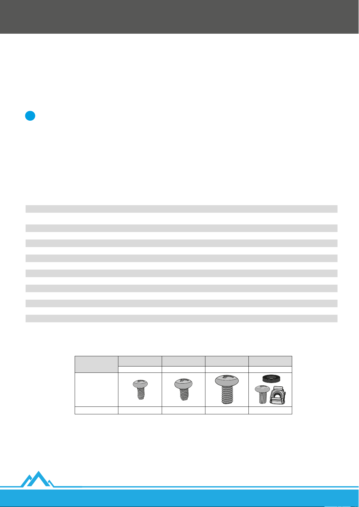
2.1.1. Table of components
Component Supplied quantity Component symbol
Front glass / metal door with 2 grounding pins 1x A
Side frame with attached side panel equipped with 2 latches 2x
Top cover with cable entry and 2 holes in the middle for 12x12 cm fans 1x D
Flat blank panel for top and bottom cable entry panel 2x E
Rear cabinet cover 1x F
Vertical mounting rails with ”U” numbered height 4x G
Wall-mount rail 1x H
M4*8 Self-tapping Phillips screw 16x I
M5*8 Self-tapping Phillips screw 8x J
M6*12 Phillips screw 8x K
M6*12 Phillips screw with M6 Cage Nut < 10 U: 12x >= 10U: 24x L
Plastic washer to be installed under the front door 1x N
Grounding kit (wire, washers, nuts) 1x M
Front door lock with keys and a at metal latch 1x O
Side door lock with keys and a curved metal latch 2x P
Bottom cover with cable entry and 4 holes with M10 threaded nut on the sides and 2 grounding pins 1x R
B
C
16
M4*8 Self-tapping
Element
Illustration
Supplied quantity 16x 8x 8x < 10 U: 12x >= 10U: 24x
Phillips screw
I J K L
M5*8 Self-tapping
Phillips screw
M6*12 Phillips screw
M6*12 Phillips screw with
M6 Cage Nut
Lanberg © 2015-2021
EN
Page 17
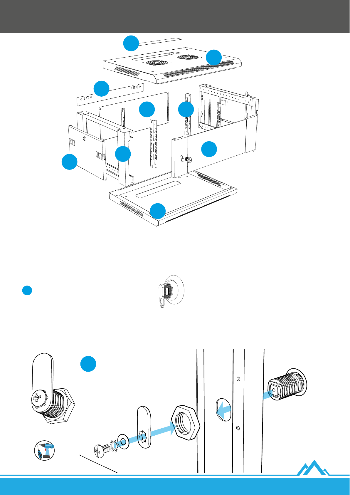
H
E
D
F G
B/C
A
B/C
R
2.2 19” cabinet installation steps
2.2.1. Front door lock installation
1. Insert the lock module from the string bag marked with [O] symbol through the door so that 2 parallel at
parts of the module are in a horizontal position. The next steps will be for other elements included in this bag.
Use the keys to set the lock in a vertical position.
i
2. Screw the washer in by inserting it with engraved triangles side towards the door onto the lock module. Finally, hold the lock module
with the door keys and try to tighten the washer tightly.
3. Apply a at vertical metal lock latch (facing upwards) to the square module element with the screw hole. Next, insert the at metal
round washer and then star-shaped one. Fix everything together by screwing the bolt into the lock module.
EN
O
Lanberg © 2015-2021
17
Page 18
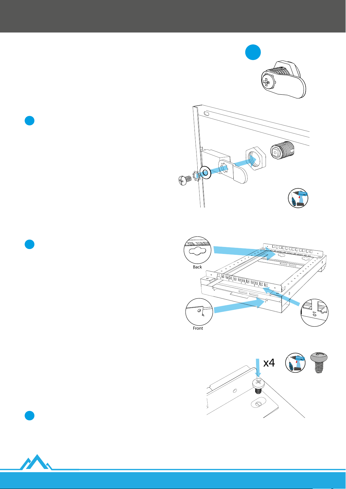
2.2.2. Side door lock installation
01
02
03
04
Back
Front
01
02
03
04
01
x4
1. Remove the side door from the side frames [B + C]. Their
reassembly will take place during the nal assembly of the
cabinet.
2. Insert the lock module from the string bag marked with [P]
symbol through the door so that 2 parallel at parts of the
module are in a horizontal position. The next steps will be for
other elements included in this bag.
Use the keys to set the lock in a horizontal position.
i
3. Screw the washer in by inserting it with engraved triangles
side towards the door onto the lock module. Finally, hold
the lock module with the door keys and try to tighten the
washertightly.
4. Apply the curved metal lock latch horizontally (curved part
facing the door) to the square module element with the screw
hole. Next, insert the at metal round washer and then starshaped one. Fix everything together by screwing the bolt into
the lock module.
5. The same steps 1 ~ 4 should be performed for the 2nd
sidedoor [C].
2.2.3. Vertical mounting rails installation
P
Before further installation, pay attention to where the front
i
and rear sides of the side frames [B + C] are.
1. Place on a at surface both side frames [B + C] (without the
doors) so that their fronts face your direction.
The distance between the centres of the small holes in the
side frames [B + C] is 25 mm.
The maximum distance (working depth) between the front
and rear vertical mounting rails (taking into account their
thickness) is:
I) For wall-mounted enclosures with a total length of 450
mm: 379.5 mm.
II) For wall-mounted enclosures with an overall length of
600 mm: 529.5 mm.
However, it is recommended to install the rear vertical
mounting rails on the 3rd hole from the end (50 mm
dierence) on the side frames to accommodate the devices
with the input plug and cable (approx. 55 mm on average).
2. Use 2 vertical mounting rails [G] and adjust the required
distance between them on the left side frame [B].
18
It is vital to make sure that the numbering of the front
i
vertical rails is in ascending order from right to left (see the
provided illustrations). Rear vertical rails also have to be
mounted the same way.
3. Use a total of 4 M5*8 self-tapping Phillips screws [J] to attach
the vertical mounting rails to the side frame - 2 screws for each
end of the rail.
Lanberg © 2015-2021
EN
Page 19
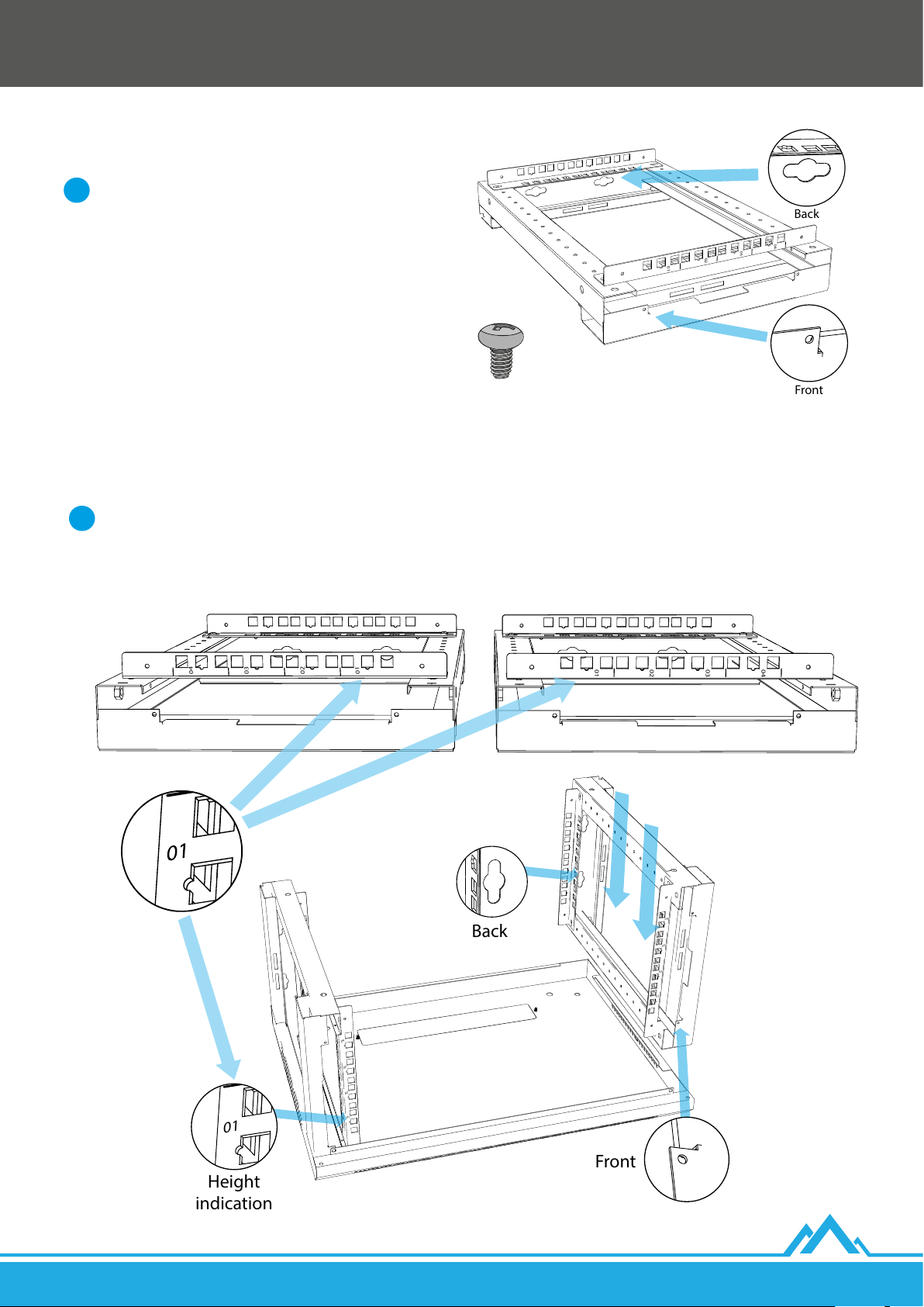
4. Use 2 numbered vertical mounting rails [G] and choose the
01
02
03
04
Back
Front
01
02
03
04
01
02
03
04
Back
Front
Height
indication
01
02
03
04
01
02
03
04
01
02
03
04
01
02
03
04
same distance as in point 2. on the right side frame [C].
It is vital to make sure that the numbering of the front
i
vertical rails is in ascending order from left to right (see the
provided illustrations). Rear vertical rails also have to be
mounted the same way.
5. Use a total of 4 M5*8 self-tapping Phillips screws [J] to attach
the vertical mounting rails to the side frame - 2 screws for
each end of the rail.
2.2.4. Installation of side frames with top and bottom cover
1. Prepare the bottom cover [R] so that the cable entry is at theback.
2. Place the left side frame [B] on the left side of the bottom cover and the rightside frame [C] on the right side of the cover.
Before proceeding with the next assembly step, make sure that:
i
I) The height numbering is ascending from bottom to top cover on the front and rear vertical mounting rails.
II) The pairs of opposite rails are mounted on the same lengths.
EN
Lanberg © 2015-2021
19
Page 20
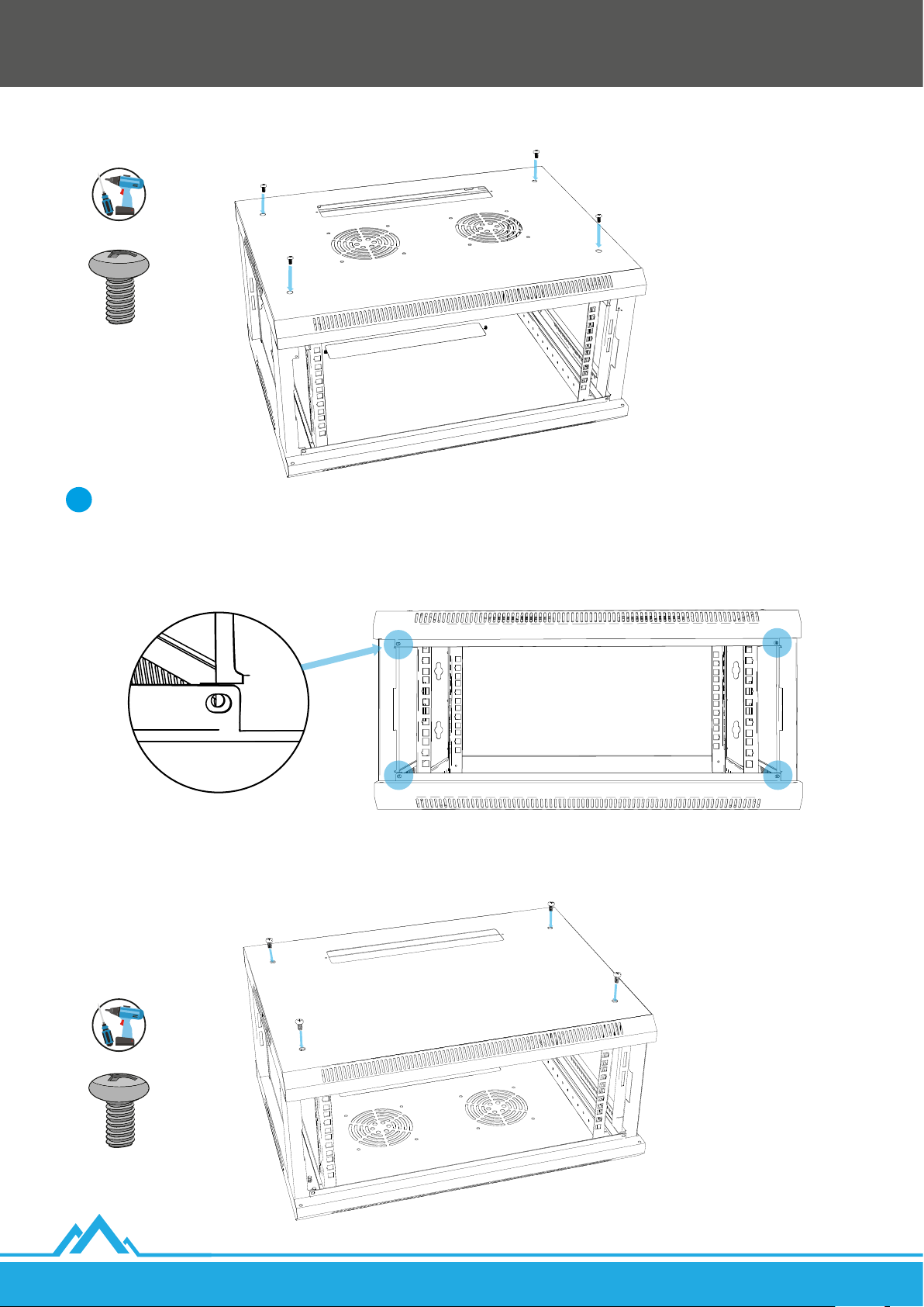
3. Place the top cover [D], with cable entry at the back, on the side frames [B + C], and adjust it to their alignment.
4. Use a total of 4 M6*12 Phillips screws [K] to attach the top cover to the side frames - 2 on each side.
Remember to:
i
I) Regularly pay attention to the position of the top cover [D] in regards to the holes in the side frames [B + C]. Do not tighten every
screw to the max! First, insert all of them at about 2/3 of their height, check the alignment, and then tighten all screws.
II) Make sure that the small holes for M4*8 self-tapping Phillips screws [I] on the front side of both covers and side frames overlap
with each other.
20
5. Rotate the whole structure 180 degrees. Adjust the bottom cover [R] to the side frames position.
6. Use a total of 4 M6*12 Phillips screws [K] to attach the bottom cover to the side frames - 2 on each side.
Lanberg © 2015-2021
EN
Page 21
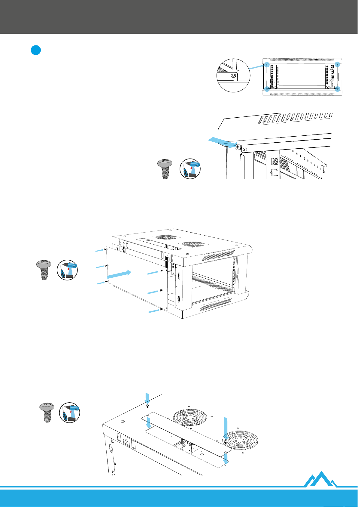
Remember to:
i
I) Regularly pay attention to the position of the bottom cover [R] in
regards to the holes in the side frames [B + C]. Do not tighten every screw
to the max! First, insert all of them at about 2/3 of their height, check the
alignment, and then tighten all screws.
II) Make sure that the small holes for M4*8 self-tapping Phillips screws [I]
on the front side of both covers and side frames overlap with each other.
7. Use a total of 4 M4*8 self-tapping Phillips screws [I] to x, on the front
side, both covers [D + P] with side frames [B + C] - 1 on each side (see
the illustration above).
2.2.5. Rear cabinet cover installation
1. Align the rear cover [F] so that its 6 holes overlap with the 6 holes at the rear of the side frames [B + C].
2. Use a total of 6 M4*8 self-tapping Phillips screws [I] to attach the rear cover to the side frames - 3 per side.
2.2.6. Flat blank panels installation
1. Align at blanking panel [E] to the cover’s lower cable entry so that the screw holes on both components overlap.
2. Use a total of 2 M4*8 self-tapping Phillips screws [I] to attach the blanking panel to the lower cable entry - 1 per each side.
3. Rotate the cabinet structure by 180 degrees.
4. Align another at blanking panel [E] with the cover’s upper cable entry so that the screw holes on both components overlap.
5. Use 2 more M4*8 self-tapping Phillips screws [I] to attach the blanking panel to the upper cable entry - 1 per each side.
EN
Lanberg © 2015-2021
21
Page 22
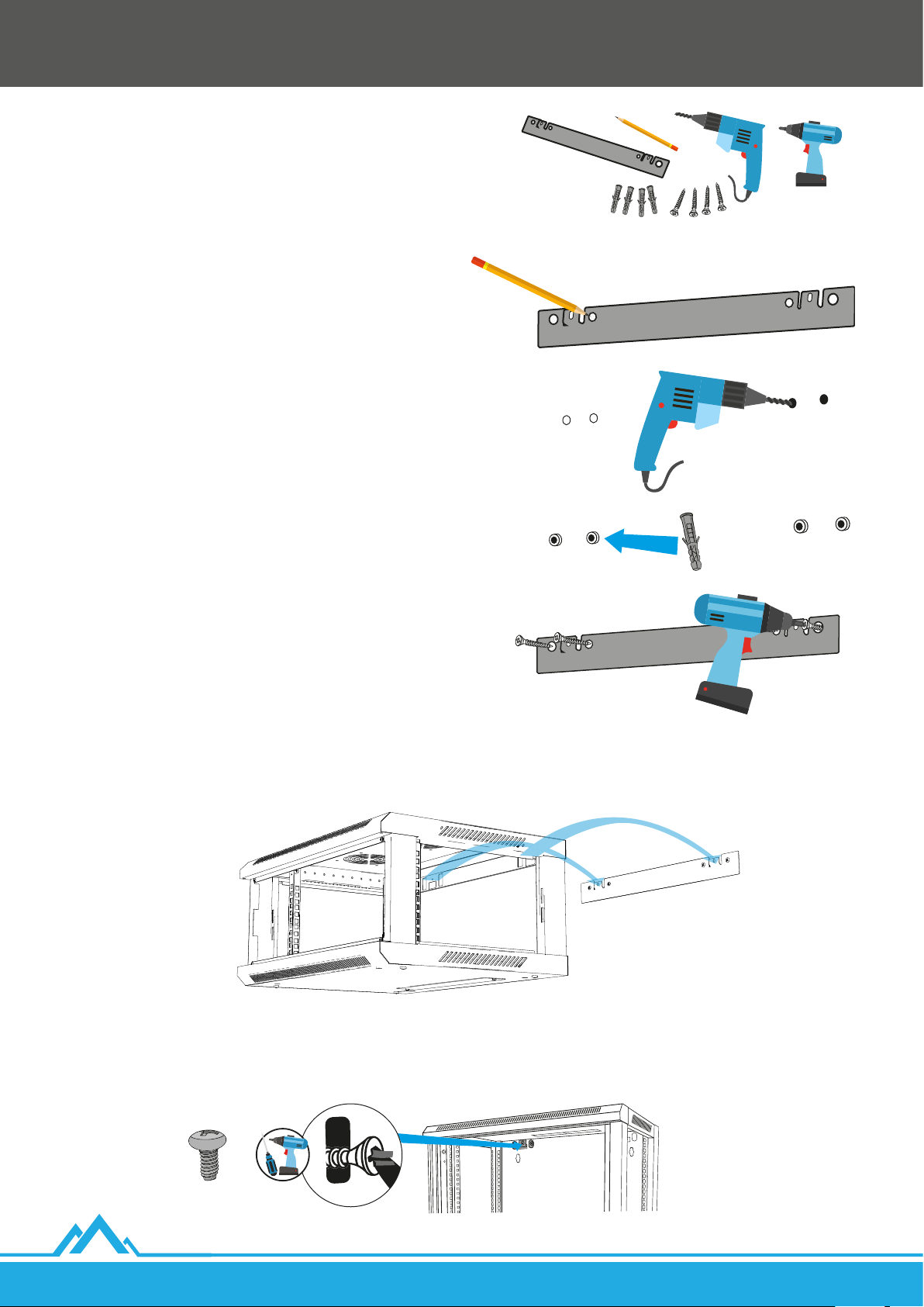
3. Cabinet wall installation
1. Prepare (your own) 4 mounting anchors and 4 screws to
match the load capacity of the cabinet’s overall weight and
the diameter to the holes of the wall-mount rail: 4 - Ø 10. The
distance between the centers of the larger holes on the rail,
per side, is 69 mm, and between the centers of the larger
holes, at the ends of the rail, (left and right) is 468 mm.
2. Align the wall-mount rail [H] with the surface of the wall and
make sure it is leveled.
3. Outline the 4 edges of the wall-mount rail holes (excluding
those on the hooks).
4. Drill 4 holes in the outlined spots, then insert the
expansionanchors.
5. Re-adjust the rail so that between its 2 L-shaped hooks and
the wall there is enough space for attaching the cabinet.
6. Screw 4 bolts into the expansion anchors. First into 2 external
holes (1 on each side), others into 2 internal holes.
7. Hang the assembled cabinet by attaching 2 holes at the back on top of the top cover [D] by 2 rail hooks.
8. Use 2 M4*8 self-tapping Phillips screws [I] to x the rear structure of the cabinet with 2 hooks on the wall-mount rail.
22
Lanberg © 2015-2021
EN
Page 23
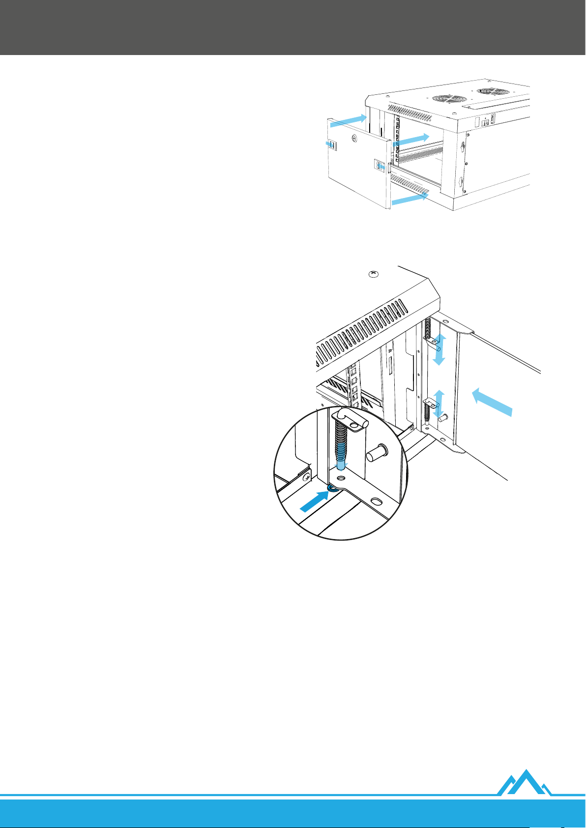
4. Side door reinstallation
1. Side doors, which should have been removed from the box at
an earlier stage of assembly, should be reinstalled in the side
frames [B + C]. Simultaneously press 2 latches in the middle of
doors, and when they are aligned with the frame holes, releasethem.
2. Use the keys [P] to lock the side frame door.
5. Front door installation
1. Put a plastic washer [N] on one of the bottom cover holes [R] on
which you plan to place the grounding pin of the front door[A].
2. Insert the lower pin of the front door [A] into the lower hole
through the plastic washer, and then insert the upper pin into
the hole on the top cover [D] by pressing the hinges (L-shaped)
inwards. Release the pressure when it is aligned with the hole.
3. Use the keys [O] to lock the front door.
6. Grounding
The cabinet has 4 grounding pins with a diameter of 6 mm:
• 2x on the front door [A].
• 2x on the bottom cover [R].
Grounding wire [M] is included. It consist of 42 conductors made of pure copper (100% CU), 0.16 mm each. The cable cross-section is
~0.9mm. A cable is used to connect the bottom cover to the front door (with the possibility of opening it at an angle of up to 180°).
To connect one of the cabinet’s main grounding pins (located on the bottom cover) to the equalizer connection a cable of appropriate
length must be purchased separately. Its AWG should be between 17 ~ 18 and the conductors must be made of pure copper (100% CU)only.
EN
Lanberg © 2015-2021
23
Page 24
1. Recomendaciones previas importantes e información relativa al uso de los armarios de pared 19” de montaje rápido
1.1 Introducción
CONSERVA ESTAS INSTRUCCIONES. El presente conjunto de recomendaciones, indicaciones, normas de seguridad, restricciones
einstrucciones de uso de los armarios de pared 19” de la marca Lanberg, se aplica para los modelos detallados a continuación:
• WF01-6404-10B
• WF01-6404-10S
• WF01-6604-10B
• WF01-6604-10S
• WF01-6406-00B
• WF01-6406-00S
• WF01-6406-10B
• WF01-6406-10S
También contiene datos logísticos, técnicos, instrucciones y reglamentos que deben ser respetados y que deben cumplirse durante el
transporte, el montaje, el uso y el eventual mantenimiento de los productos. En ningún caso se debe utilizar el dispositivo sin haber leído
con atención toda la información contenida en el manual de instrucciones. Esta información debe ser respetada en su totalidad. Conserva
estas instrucciones para su uso en el futuro. Todas las fotografías o guras contenidas en las instrucciones tienen carácter ilustrativo. La
información contenida en el presente manual de instrucciones ha sido comprobada y se considera suciente. El proveedor no asume la
responsabilidad por ninguna inexactitud que pueda estar contenida en este documento, ni se compromete a actualizar o mantener al
corriente la información en estas instrucciones o a noticar a los usuarios u organizaciones su actualización. En particular, los propietarios de
la marca Lanberg no asumen la responsabilidad por ningún equipo, software o datos almacenados o utilizados con el producto, incluyendo
los costes de reparación, sustitución, integración, instalación o recuperación de equipos, software o datos en caso de un uso indebido del
producto o de sus elementos.
Los propietarios de la marca Lanberg se reservan el derecho de introducir modicaciones en las presentes instrucciones en cualquier
momento y sin previo aviso. Los productos mencionados en las presentes instrucciones, incluyendo la documentación, son propiedad de
los propietarios de la marca Lanberg y de sus licenciantes. Cualquier uso o reproducción de estos productos, junto con la documentación,
está prohibido, a excepción de un permiso explícito en las correspondientes condiciones de la licencia.
ATENCIÓN: Para conseguir la versión más actual de estas instrucciones rogamos visitar nuestra página web en la dirección www.lanberg.pl.
• WF01-6606-00B
• WF01-6606-00S
• WF01-6606-10B
• WF01-6606-10S
• WF01-6409-00B
• WF01-6409-00S
• WF01-6409-10B
• WF01-6409-10S
• WF01-6609-00B
• WF01-6609-00S
• WF01-6609-10B
• WF01-6609-10S
• WF01-6412-00B
• WF01-6412-00S
• WF01-6412-10B
• WF01-6412-10S
• WF01-6612-00B
• WF01-6612-00S
• WF01-6612-10B
• WF01-6612-10S
• WF01-6415-10B
• WF01-6415-10S
• WF01-6615-10B
• WF01-6615-10S
• WF01-6418-10B
• WF01-6418-10S
• WF01-6618-10B
• WF01-6618-10S
• WF01-6422-10B
• WF01-6422-10S
• WF01-6622-10B
• WF01-6622-10S
• WF01-6427-10B
• WF01-6427-10S
• WF01-6627-10B
• WF01-6627-10S
1.2 Conformidad con las disposiciones legales y regulaciones relativas a la seguridad y el medio ambiente
Este producto es conforme con los reglamentos de la Unión Europea (UE) relativos a la seguridad y el medio ambiente.
Los productos mencionados en las presentes instrucciones han sido aprobados para su comercialización en el territorio de la UE,
consiguiendo una declaración de conformidad de la Unión Europea, que contiene una declaración con los requisitos fundamentales
y otras disposiciones aplicables de las siguientes directivas, y se han aplicado las normas armonizadas mencionadas a continuación.
Directiva: RoHS 2011/65/UE + 2015/863/UE
Normas: IEC 62321-4:2013 + A1:2017; IEC 62321-5:2013;
IEC 62321-6:2015; IEC 62321-7-2:2017; IEC 62321-8:2017;
Con el desarrollo de los productos y la actualización de los reglamentos CE la declaración puede sufrir cambios. La declaración de
conformidad (CE) más reciente se encuentra en la página: www.lanberg.pl.
ATENCIÓN: El uso del símbolo WEEE (contenedor de basura tachado) signica que estos productos no pueden ser tratados como
un residuo doméstico. La correcta recuperación de los equipos utilizados permite evitar riesgos para la salud humana y el medio
ambiente resultantes de la posible presencia en los equipos de sustancias o mezclas peligrosas, así como de componentes, además
del almacenamiento y el procesamiento indebidos de tales equipos. La recogida selectiva también permite recuperar los materiales
y componentes con los que fue fabricado el dispositivo. Para conseguir información detallada sobre el reciclado de los presentes
productos es necesario contactar con el punto de venta al por menor en el que se realizó la compra o bien con las autoridades locales.
1.3 Contenido del embalaje
The following items should be provided in the shipping packaging:
• (1x) Puerta delantera equipada con dos 2 clavijas de puesta a tierra.
• (2x) Marco lateral del armario con puerta jada, equipada con 2 pestillos.
• (1x) Tapa superior con pasacables y 2 oricios en el centro para ventiladores de 12x12 cm.
• (2x) Tapón plano para el pasacables superior e inferior.
• (1x) Tapa posterior del armario.
• (4x) Carriles de montaje verticales numerados para el montaje de dispositivos en el estándar RACK.
• (1x) Raíl para el montaje en la pared.
• Accesorios de montaje necesarios en una bolsa con cierre zip: (16x) tornillos con cabeza de estrella M4*8 autorroscantes; (8x)
tornillos con cabeza de estrella M5*8 autorroscantes; (8x) tornillos con cabeza de estrella M6*12; (1x) arandela de plástico; (1x)
conjunto de puesta a tierra (cable, arandelas, tuercas); (1x) cerradura de la puerta delantera con llavero, dos llaves y lengüeta
metálica plana; (2x) cerradura de la puerta lateral con llavero, dos llaves y lengüeta metálica curva; (12x para el tamaño < 12 U; 24x
para el tamaño >= 12 U) tornillos con cabeza de estrella M6*12 con tuercas enjauladas M6; (1x) instrucciones en papel.
• (1x) Tapa inferior con pasacables y 4 oricios para tornillos M10 en los laterales y 2 clavijas de puesta a tierra.
24
Lanberg © 2015-2021
ES
Page 25

1.4 Indicaciones generales sobre seguridad y medidas de precaución
• Se debe respetar estrictamente la especicación del dispositivo durante su uso y al conectarlo a cualquier producto exterior. También
deben respetarse las especicaciones de los productos exteriores, a los que el presente dispositivo deba ser conectado.
• Está prohibido utilizar el producto para un funcionamiento fuera de los valores nominales indicados en su especicación. Cualquier
daño provocado por una desviación de estos valores durante el uso del dispositivo no está cubierto por la garantía.
• Cualquier instalación, conexión, cableado y circuito en los que sea utilizado el producto debe ser realizado de manera conforme con
los reglamentos locales vigentes en materia de electricidad y de tal forma que se elimine el riesgo de tropezar o resbalar con ellos.
Utiliza solo cables de alimentación con certicado VDE y CE para la conexión con el dispositivo. Es necesario emplear los mismos
procedimientos mencionados en este punto al conectar el cableado al producto, o este mismo a elementos exteriores.
• En el caso de dispositivos exteriores conectados al presente producto, es necesario respetar estrictamente las instrucciones de uso
facilitadas por sus fabricantes.
• Para garantizar la seguridad y la conformidad se deben utilizar únicamente componentes conformes con la especicación o las piezas
recomendadas por el fabricante.
• Durante la vigencia de la garantía está prohibida la sustitución de cualquier elemento del producto por sus usuarios. Encarga el mantenimiento
únicamente a personal técnico cualicado, como, por ejemplo, el servicio técnico del fabricante o un importador autorizado.
• Si fuese necesario el mantenimiento del dispositivo, deberá ser llevado a cabo o supervisado por una persona que disponga de las
cualicaciones adecuadas para trabajar con este, así como conocimientos acerca del cumplimiento de las medidas de precaución
oportunas. Todo esto de conformidad con los reglamentos vigentes.
• Si fuese necesario el mantenimiento del dispositivo u otras acciones que requieran trabajar en el interior del dispositivo o el contacto
con elementos que puedan estar bajo una potencial tensión, antes de llevar a cabo estas acciones se deben respetar las siguientes
normas de seguridad: quitarse cualquier pulsera, collar, anillo, reloj u otro objeto metálico de las manos y del cuello y utilizar
herramientas con mangos aislados.
• Antes de iniciar el mantenimiento del dispositivo deberá encontrarse cerca una persona que pueda reaccionar y emprender las
acciones adecuadas con el n de ayudar a la persona que realiza el mantenimiento en caso de accidente. La persona que realiza el
mantenimiento deberá siempre lavarse las manos tras el trabajo con el dispositivo.
• NUNCA permitas una situación en la que pueda generarse cualquier chispa o llama cerca del dispositivo. La aparición de esta situación
puede tener consecuencias muy negativas para las personas y las cosas que se encuentren cerca.
• En caso de incendio, desconecta inmediatamente y (si es posible) sin demoras innecesarias la alimentación de red y avisa a los
bomberos de la situación acontecida, llamando al número de emergencias correspondiente al país en el que te encuentres.
• El producto está destinado para un uso en interiores. No se debe reconstruir ni modicar el producto o sus componentes.
• En ningún caso está permitido introducir en el dispositivo productos que no estén destinados para tal n.
• El fabricante y el distribuidor no son responsables de ningún daño causado como consecuencia de un uso indebido y una manipulación
indebida del producto (no conformes con las presentes instrucciones).
• Antes de iniciar acciones relacionadas con la jación o la desconexión del dispositivo, la conexión o la desconexión de cables en el
armario de pared de 19”, conecta todos sus elementos a una puesta a tierra vericada y que funcione ecazmente.
• Comprueba que todos los elementos jados originalmente al armario de pared de 19”, así como los equipos jados por el usuario,
están correctamente atornillados o desatornillados cuando se realiza el desmontaje. No es aceptable una situación en la que cualquier
elemento del producto o asociado a este no esté correctamente jado / empleado o suponga un riesgo debido a su aislamiento
erróneo de los demás elementos en funcionamiento, que en caso de contacto podrían provocar un riesgo.
1.5 Indicaciones relativas a las normas de seguridad ESD
• Para evitar daños del producto, del sistema o de los subconjuntos eléctricos por una descarga electrostática (ESD) es importante
prepararse bien durante el trabajo con ellos y manejarlos con cuidado. En general, las siguientes medidas son sucientes para proteger
el producto frente a la aparición de ESD:
• No utilices pulseras metálicas en las manos para evitar descargas estáticas.
• Antes de comenzar el trabajo toca un objeto metálico puesto a tierra.
• Durante el manejo de dispositivos eléctricos se debe evitar el contacto con clavijas, enchufes o cualquier relé de energía.
• Al desplazar elementos electrónicos se recomienda agarrarlos únicamente por sus bordes (aislados), donde no se produce ningún
ujo de corriente. No toques los subconjuntos, circuitos integrados, módulos de memoria, contactos, etc.
• Vuelve a meter todos los dispositivos electrónicos en bolsas antiestáticas (si es posible) cuando no son utilizados.
1.6 Transporte
Durante el transporte se debe almacenar el producto única y exclusivamente en el embalaje original con el n de protegerlo frente a sacudidas
y golpes. El embalaje no debe arrojarse a la basura. En caso de enviar un producto en garantía, es obligatorio utilizar la caja original.
1.7 Garantía
No se tiene derecho a la garantía en caso de aparecer averías y defectos causados por un uso o manipulación indebidos del dispositivo
(no conformes con las presentes instrucciones). Los daños mecánicos son motivo para rechazar una reclamación. Para enviar una
reclamación de garantía o saneamiento de vicios ocultos contacta con tu vendedor.
1.8 Desembalado y control
En presencia del transportista, desembala con cuidado el producto de la caja de transporte y comprueba que:
• El contenido del embalaje incluye los elementos mencionados en el punto 1.3.
• Los elementos no están dañados.
En caso de ausencia, daño o inexactitud en cuanto a los elementos mencionados en el punto 1.3 se debe redactar un acta de daños (en
caso de su aparición) y comunicar obligatoriamente este asunto al vendedor. Se requieren: fotografías, número de lote y descripción del
problema. Estas acciones deben realizarse el mismo día de la fecha de suministro del producto.
ES
Lanberg © 2015-2021
25
Page 26
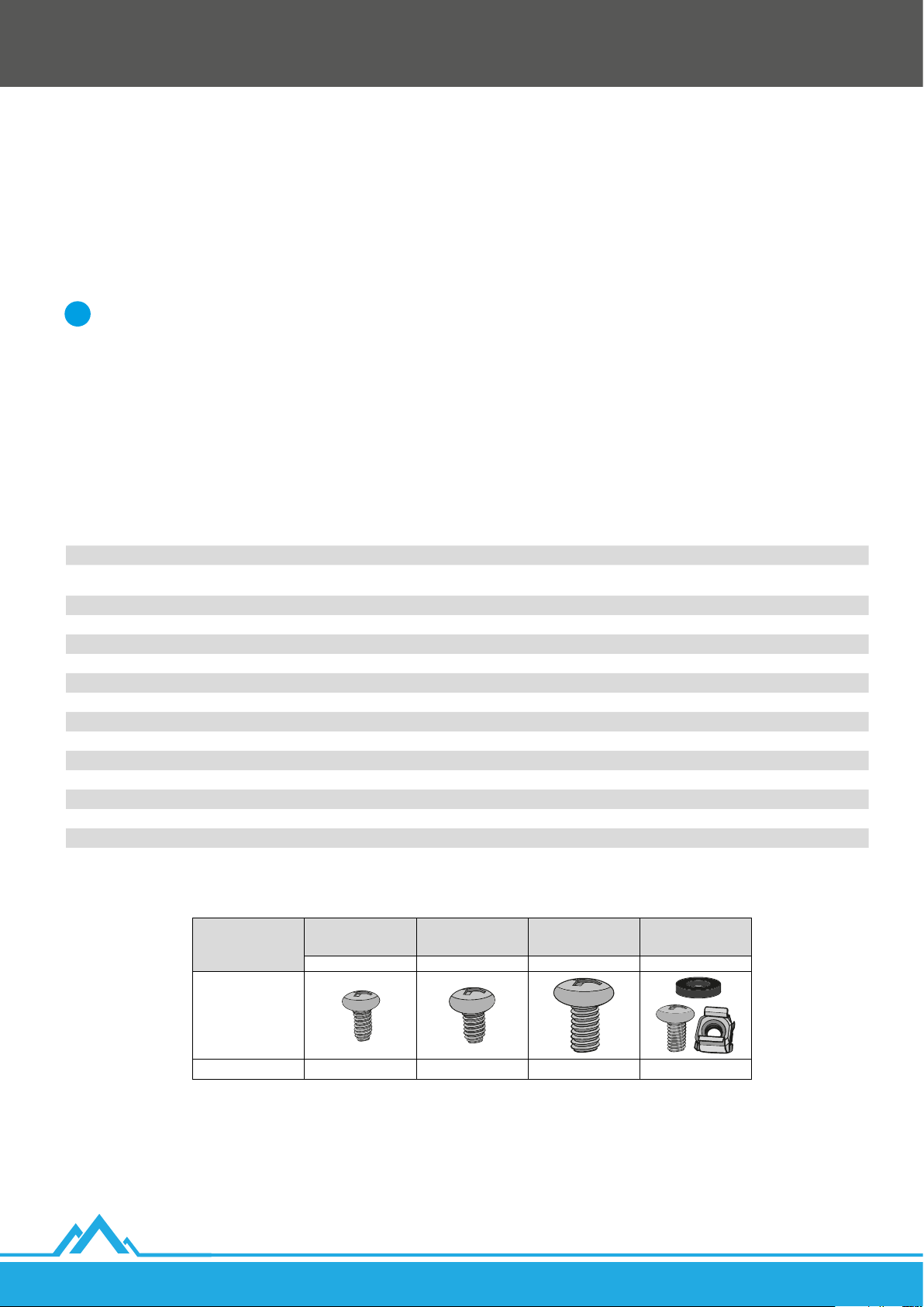
1.9 Almacenamiento y ventilación
• El producto deberá ser instalado únicamente en una localización con acceso limitado (espacios destinados para equipos, etc.).
• No se debe instalar ni almacenar en lugares en los que esté presente agua estancada o corriente, humedad o cualquier otra sustancia líquida.
• Se debe evitar exponer el dispositivo a la acción directa de los rayos solares.
• Coloca el dispositivo en una supercie estable y seca en un lugar bien ventilado. Deja al menos 100 mm de espacio libre alrededor de
él para garantizar una ventilación adecuada.
• El dispositivo está destinado para un funcionamiento única y exclusivamente en un entorno controlado (temperatura controlada
y umedad del ambiente conforme con la información contenida en la especicación, funcionamiento en el interior de un edicio, sin
contaminantes conductores [polvo, gases inamables, sustancias que produzcan corrosión, etc.]).
2. Montaje
Se deben respetar estrictamente las recomendaciones contenidas en estas instrucciones.
i
2.1 Preparación
Prepara el espacio adecuado en el soporte sobre el que tendrá lugar el montaje. Saca con cuidado todos los elementos de la caja de
transporte. Las siguientes instrucciones de montaje se basarán en el esquema incluido. Prepara también 4 tacos (propios) y 4 tornillos
con una capacidad de carga adaptada al peso total previsto del armario y al diámetro de los oricios del raíl de montaje en la pared, que
es: 4 – Ø 10.
Debido al uso de tornillos con cabeza de estrella M6*12 para jar la tapa superior e inferior a los marcos laterales, recomendamos preparar
un buen destornillador de estrella. La especicación recomendada es PH3x150 mm.
2.1.1. Lista de elementos
Componente Cantidad suministrada Símbolo
Puerta delantera acristalada / metálica equipada con dos 2 clavijas de puesta a tierra 1x A
Marco lateral del armario con puerta jada, equipada con 2 pestillos 2x
Tapa superior con pasacables y 2 oricios en el centro para ventiladores de 12x12 cm 1x D
Tapón plano para el pasacables superior e inferior 2x E
Tapa posterior del armario 1x F
Carriles verticales de montaje numerados 4x G
Raíl para el montaje en la pared. 1x H
Tornillo con cabeza de estrella autorroscante M4*8 16x I
Tornillo con cabeza de estrella autorroscante M5*8 8x J
Tornillo con cabeza de estrella M6*12 8x K
Tornillo con cabeza de estrella M6*12 con tuercas enjauladas M6 < 10 U: 12x >= 10U: 24x L
Arandela de plástico para la puerta delantera 1x N
Conjunto de puesta a tierra (cable, arandelas, tuercas) 1x M
Cerradura de la puerta delantera con llavero, dos llaves y lengüeta metálica plana 1x O
Cerradura de la puerta lateral con llavero, dos llaves y lengüeta metálica curva 2x P
Tapa inferior con pasacables y 4 oricios M10 en los laterales y 2 clavijas de puesta a tierra. 1x R
B
C
26
Tornillo con cabeza de
Elemento
Figura
Cantidad suministrada 16x 8x 8x < 10 U: 12x >= 10U: 24x
estrella autorroscante
M4*8
I J K L
Tornillo con cabeza de
estrella autorroscante
M5*8
Tornillo con cabeza de
estrella M6*12
Tornillo con cabeza de
estrella M6*12 con tuercas
enjauladas M6
Lanberg © 2015-2021
ES
Page 27
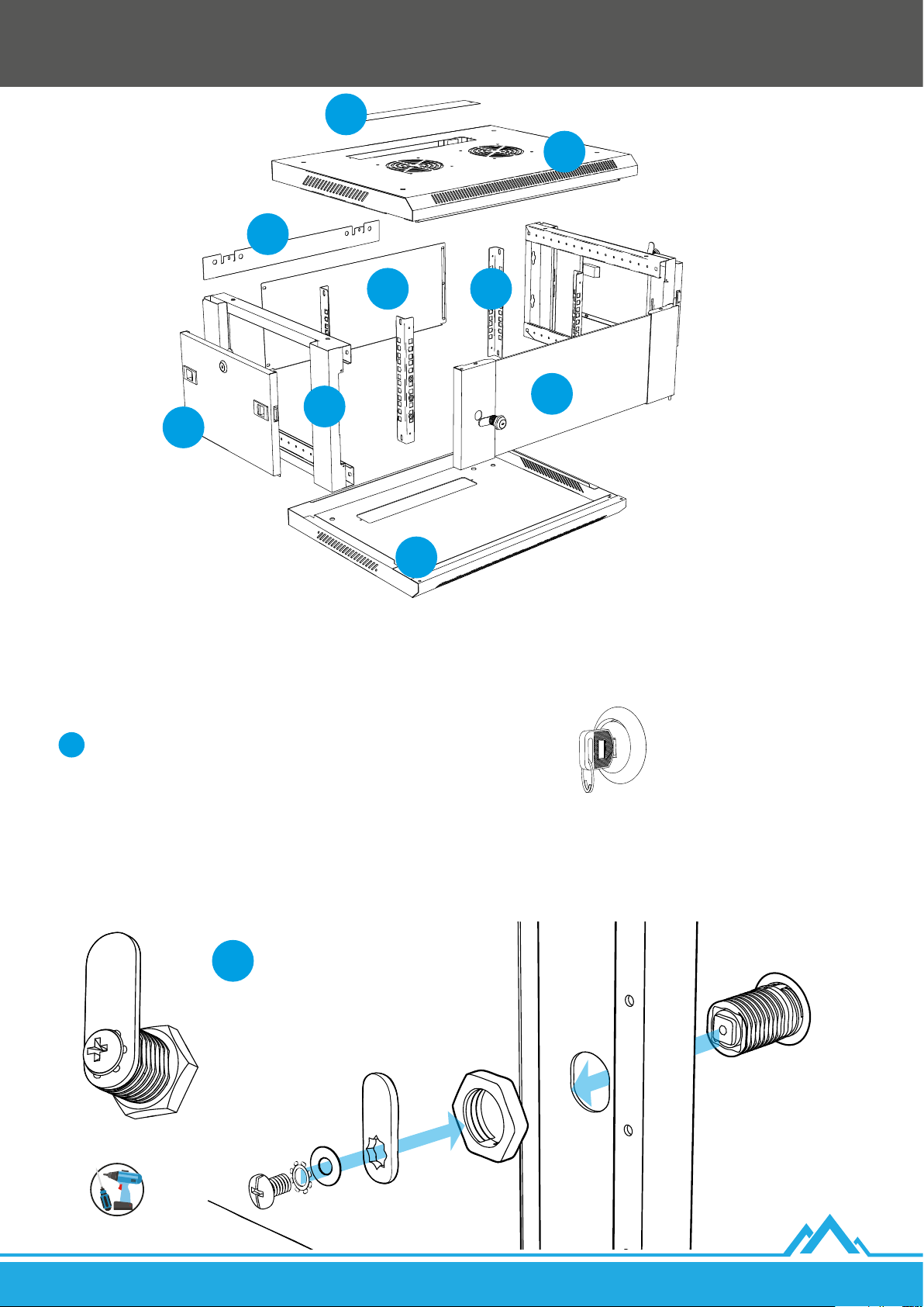
H
E
D
F G
B/C
A
B/C
R
2.2 Montaje del armario de pared 19” de la serie WF01 V2
2.2.1. Montaje de la cerradura en la puerta delantera
1. Introduce el módulo de la cerradura de la bolsa con cierre zip marcado con el símbolo [O] a través de a puerta de forma que las dos
partes planas paralelas del módulo se encuentren en posición horizontal. Los siguientes pasos harán referencia a los elementos que
se encuentran en esta bolsa.
Coloca el módulo de la cerradura en posición vertical con ayuda de las llaves.
i
2. Aprieta la tuerca introduciéndola con la parte con los triángulos grabados dirigida hacia la puerta en el módulo de la cerradura.
Finalmente, sujeta el módulo de la cerradura mediante las llaves e intenta apretar bien la tuerca.
3. Coloca la lengüeta metálica plana de la cerradura verticalmente (dirigida: hacia arriba si la puerta está colocada como en la siguiente
gura o en caso contrario hacia abajo) en el elemento cuadrado del módulo con un oricio para el tornillo. Luego coloca la arandela
metálica redonda plana y a continuación la de forma estrellada. Fija el conjunto apretando el tornillo al módulo de la cerradura.
ES
O
Lanberg © 2015-2021
27
Page 28
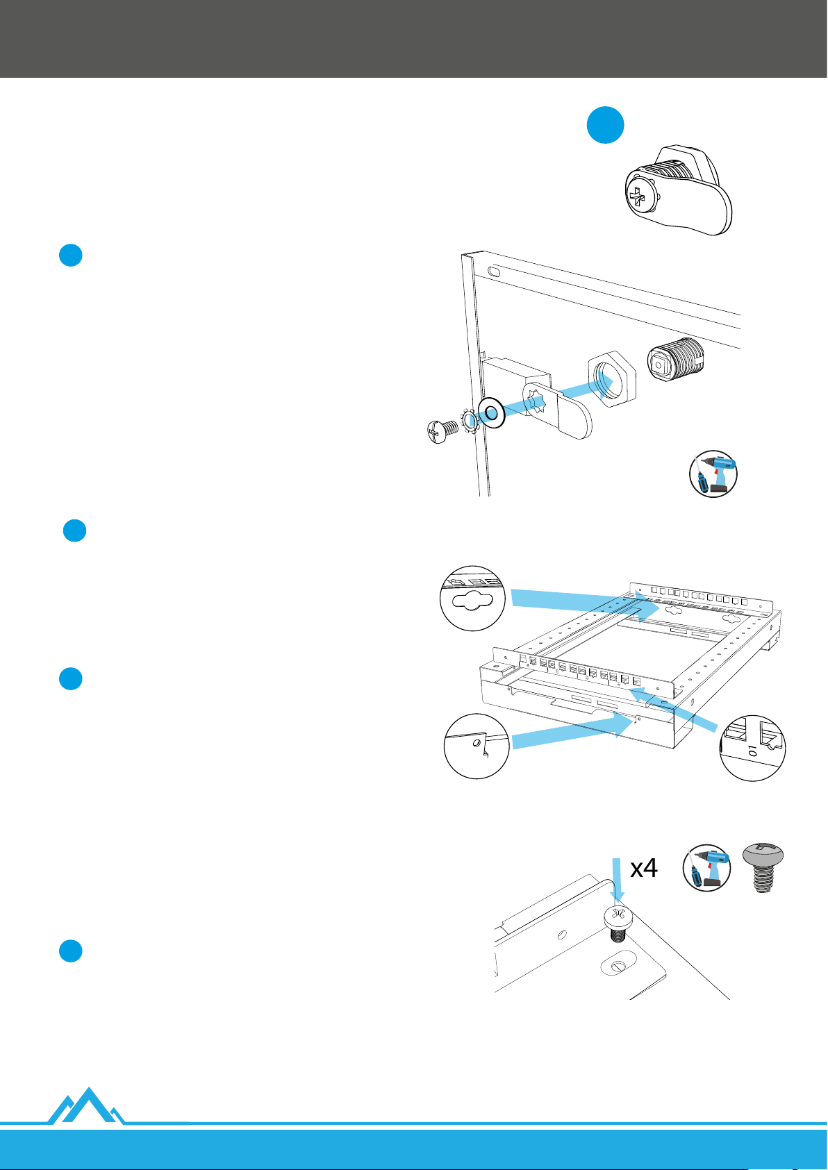
2.2.2. Montaje de la cerradura en las puertas laterales
01
02
03
04
Back
Front
01
02
03
04
01
x4
1. Saca las puertas laterales de los marcos laterales [B + C]. Su nuevo
montaje tiene lugar en la etapa nal de montaje del armario.
2. Introduce el módulo de la cerradura de la bolsa con cierre zip
marcado con el símbolo [P] a través de a puerta de forma que
las dos partes planas paralelas del módulo se encuentren en
posición horizontal. Los siguientes pasos harán referencia a
los elementos que se encuentran en esta bolsa.
Coloca el módulo de la cerradura en posición horizontal
i
con ayuda de las llaves.
3. Aprieta la tuerca introduciéndola con la parte con los
triángulos grabados dirigida hacia la puerta en el módulo
de la cerradura. Finalmente, sujeta el módulo de la cerradura
mediante las llaves e intenta apretar bien la tuerca.
4. Coloca la lengüeta metálica curva de la cerradura en posición
horizontal (la parte doblada dirigida hacia la puerta) en
el elemento cuadrado del módulo con un oricio para el
tornillo. Luego coloca la arandela metálica redonda plana
y a continuación la de forma estrellada. Fija el conjunto
apretando el tornillo al módulo de la cerradura.
5. Realiza de igual forma los pasos 1 ~ 4 para la otra puerta lateral [C].
2.2.3. Montaje de los carriles de montaje verticales
P
Antes de continuar con el montaje presta atención a dónde
i
se encuentran la parte delantera y posterior de los marcos
laterales [B + C].
La distancia entre los centros de los oricios pequeños
situados en los marcos laterales [B + C] es de 25 mm.
La distancia máxima (profundidad de trabajo) entre los
carriles de montaje verticales delanteros y posteriores
(teniendo en cuenta su grosor) es:
I) Para armarios de pared de longitud total 450 mm: 379.5 mm.
i
II) Para armarios de pared de longitud total 600 mm: 529.5 mm.
No obstante, se recomienda el montaje de los carriles
de montaje posteriores en los terceros oricios desde el
extremo, situados en los marcos laterales (diferencia 50
mm), para dejar sitio para los dispositivos con el enchufe
yel cable (en promedio, unos 55 mm).
1. Coloca los dos marcos laterales en una posición plana [B + C]
(sin las puertas montadas), de manera que estén dirigidos con
la parte delantera hacia ti.
2. Utiliza 2 carriles de montaje verticales numerados [G] y elige la
distancia requerida entre ellos en el marco lateral izquierdo [B].
Detrás
Delante
28
Es necesario prestar atención a que la numeración
i
de los carriles verticales delanteros aumente de
derecha a izquierda (mirando en la gura presentada)
yanálogamente para los posteriores.
3. Utiliza en total 4 tornillos con cabeza de estrella M5*8 [J] para
jar los carriles de montaje verticales al marco lateral: 2 en
cada extremo del carril.
Lanberg © 2015-2021
ES
Page 29
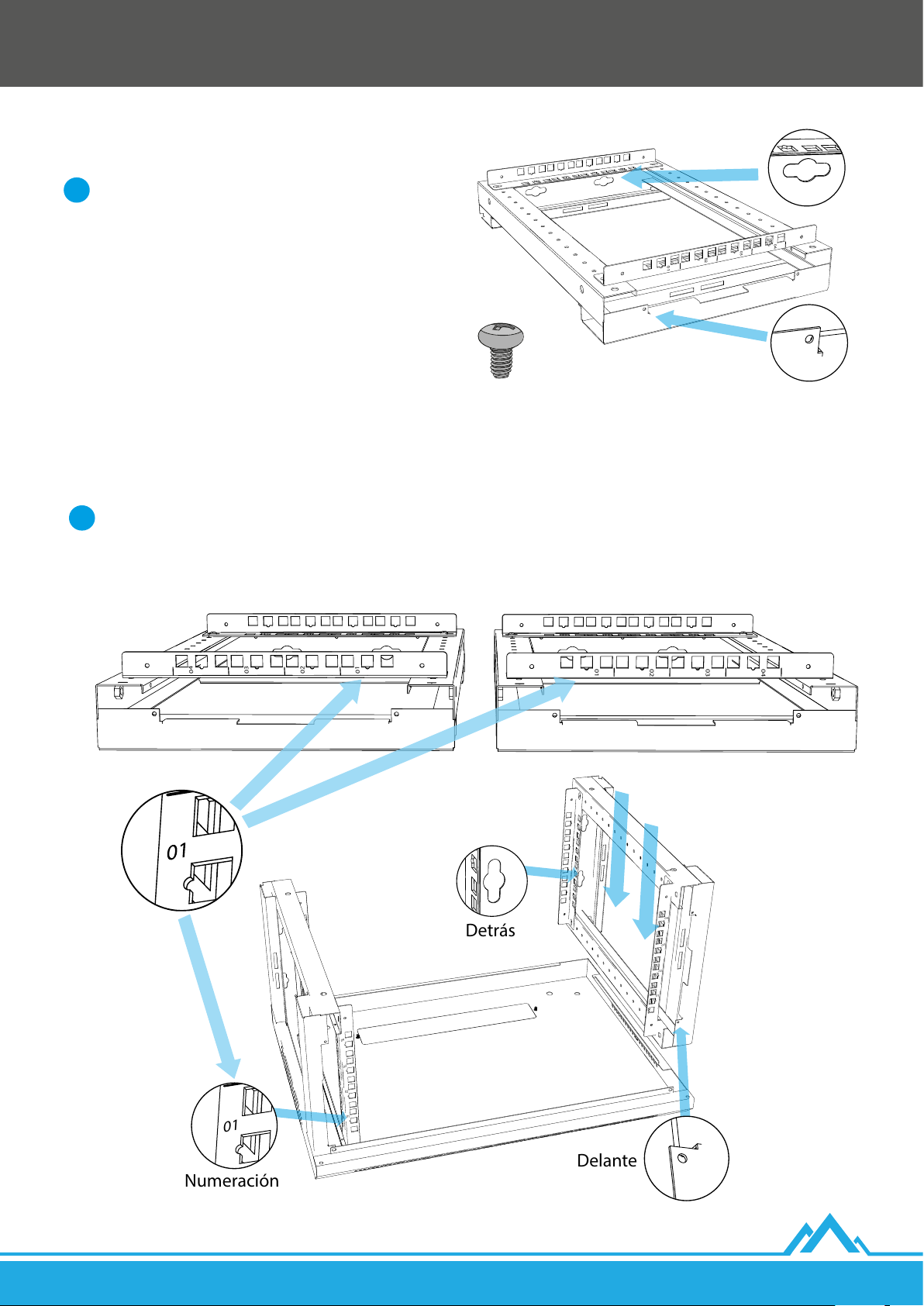
4. Utiliza 2 carriles de montaje verticales numerados [G] y elige
01
02
03
04
Back
Front
01
02
03
04
01
02
03
04
Detrás
Delante
Numeración
01
02
03
04
01
02
03
04
01
02
03
04
01
02
03
04
la misma distancia que en el punto 2 en el marco lateral
derecho [C].
Es necesario prestar atención a que la numeración
de los carriles verticales delanteros aumente de
i
izquierda aderecha (mirando en la gura presentada)
yanálogamente para los posteriores.
Detrás
5. Utiliza en total 4 tornillos con cabeza de estrella M5*8 [J] para
jar los carriles de montaje verticales al marco lateral: 2 en
cada extremo del carril.
Delante
2.2.4. Montaje de los marcos laterales con la tapa inferior y superior
1. Prepara la tapa inferior [R] de tal forma que el pasacables se encuentre detrás.
2. Coloca el marco lateral izquierdo [B] en la parte izquierda de la tapa inferior y el marco lateral derecho [C] en la parte derecha de la tapa.
Antes de pasar a la siguiente etapa del montaje, comprueba que:
i
I) La numeración aumenta desde la tapa inferior a la superior en los carriles de montaje delanteros y posteriores.
II) Las parejas de carriles opuestos están montados con las mismas longitudes.
ES
Lanberg © 2015-2021
29
Page 30
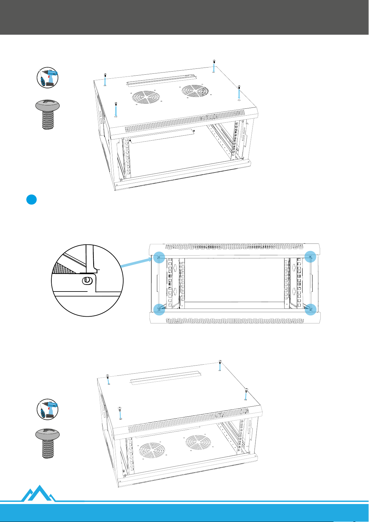
3. Coloca la tapa superior [D] con el pasacables situado detrás en los marcos laterales [B + C] y ajústala a su estructura.
4. Utiliza en total 4 tornillos con cabeza de estrella M6*12 [K] para jar la tapa superior a los marcos laterales: 2 en cada lado.
Recuerda:
i
I) Prestar sistemáticamente atención al ajuste de la tapa superior [D] a los oricios de los marcos laterales [B + C]. ¡No aprietes todos
los tornillos al 100%! Introdúcelos en primer lugar todos a 2/3 de altura, comprueba el ajuste, y a continuación apriétalos todos.
II) Prestar también atención a que los oricios pequeños para los tornillos M4*8 [I] situados en la parte delantera de ambas tapas,
así como de los marcos laterales, se correspondan entre sí.
30
5. Gira toda la estructura 180 grados. Ajusta la tapa inferior [R] a la estructura de los marcos laterales.
6. Utiliza en total 4 tornillos con cabeza de estrella M6*12 [K] para jar la tapa inferior a los marcos laterales: 2 en cada lado.
Lanberg © 2015-2021
ES
Page 31
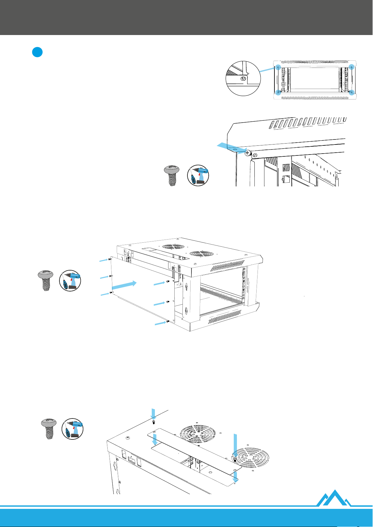
Recuerda:
i
I) Prestar sistemáticamente atención al ajuste de la tapa inferior [R] a los
oricios de los marcos laterales [B + C]. ¡No aprietes todos los tornillos al
100%! Introdúcelos en primer lugar todos a 2/3 de altura, comprueba el
ajuste, y a continuación apriétalos todos.
II) Prestar también atención a que los oricios pequeños para los
tornillos M4*8 [I] situados en la parte delantera de ambas tapas, así
como de los marcos laterales, se correspondan entre sí.
7. Utiliza en total 4 tornillos con cabeza de estrella autorroscantes M4*8 [I]
para jar la parte delantera de ambas tapas [D + P] con los marcos laterales
[B + C]: 1 a cada lado.
2.2.5. Montaje de la tapa posterior
1. Ajusta la tapa posterior [F] de forma que sus 6 oricios se correspondan con los 6 oricios situados en la parte posterior de los
marcos laterales [B + C].
2. Utiliza en total 6 tornillos con cabeza de estrella M4*8 [I] para jar la tapa posterior a los marcos laterales: 3 en cada lado.
2.2.6. Montaje de los tapones planos
1. Ajusta el tapón plano [E] al pasacables inferior de la tapa de manera que los oricios para los tornillos de ambos elementos se correspondan.
2. Utiliza en total 2 tornillos con cabeza de estrella M4*8 [I] para jar el tapón al pasacables inferior: 1 en cada lado.
3. Gira la estructura del armario 180 grados.
4. Ajusta el siguiente tapón plano [E] al pasacables superior de la tapa de manera que los oricios para los tornillos de ambos
elementos se correspondan.
5. Utiliza otros 2 tornillos con cabeza de estrella M4*8 [I] para jar el tapón al pasacables superior: 1 en cada lado.
ES
Lanberg © 2015-2021
31
Page 32
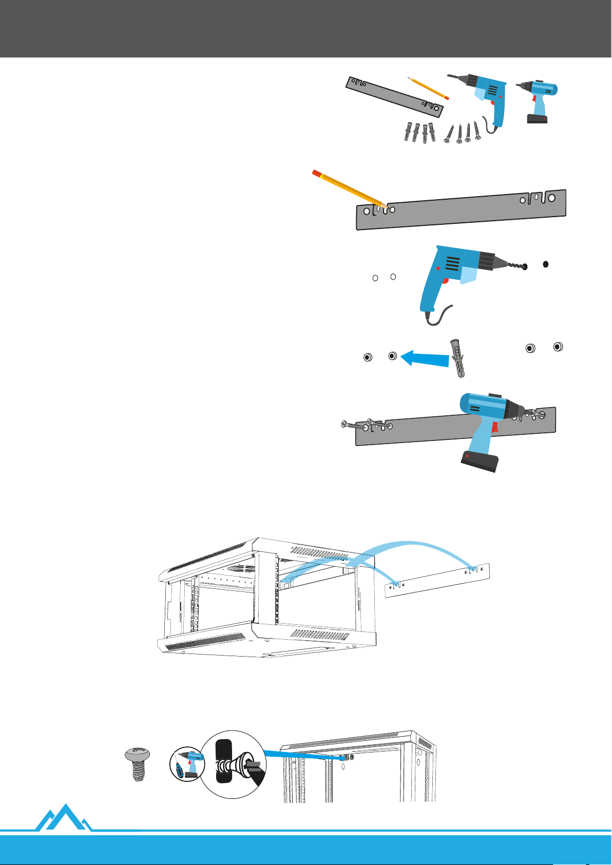
3. Montaje del armario en la pared
1. Prepara 4 tacos (propios) y 4 tornillos con una capacidad
de carga adaptada al peso total previsto del armario y
al diámetro de los oricios del raíl de montaje en la pared, que
es: 4 - Ø 10. La distancia entre los centros de los oricios más
grandes situados en el raíl en un lado es de 69 mm y entre los
centros de los oricios más grandes situados en los extremos
del raíl (izquierdo y derecho) es de 468 mm.
2. Ajusta el raíl de montaje en la pared [H] a la supercie de la
pared y nivélalo.
3. Dibuja los 4 bordes de los oricios del raíl (sin tener en cuenta
los de los enganches).
4. Taladra 4 oricios en el lugar de los contornos y a continuación
introduce los tacos.
5. Vuelve a ajustar el raíl de forma que entre sus 2 enganches
(en forma de letra «L») y la pared haya espacio para colgar
el armario.
6. Atornilla los 4 tornillos en los tacos. En primer lugar los 2 oricios
exteriores (1 a cada lado) y a continuación los 2 interiores.
7. Cuelga el armario montado sujetando los 2 oricios situados detrás en la parte superior de la tapa superior [D] en los 2enganches del raíl.
32
8. Mediante 2 tornillos con cabeza de estrella autorroscantes M4*8 [I] atornilla la estructura posterior del armario a los 2 enganches
situados en el raíl para el montaje en la pared.
Lanberg © 2015-2021
ES
Page 33
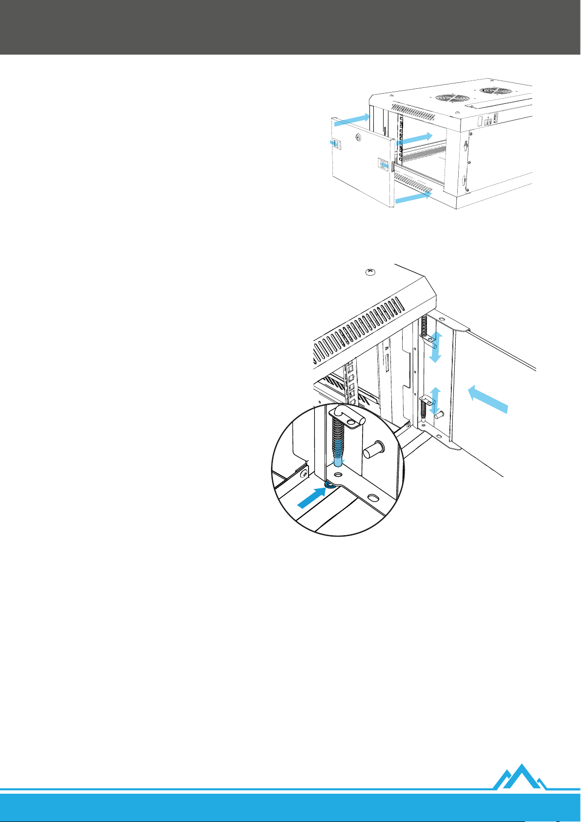
4. Montaje de las puertas laterales
1. Vuelve a montar las puertas laterales, que tuvimos que retirar en una
etapa previa del montaje, en los marcos laterales [B + C] presionando
simultáneamente hacia dentro los 2 pestillos y, en el momento en que
estén a la altura de los oricios de los marcos, libera la presión.
2. Utilizando las llaves [P] cierra las puertas de los marcos laterales.
5. Montaje de la puerta delantera
1. En uno de los oricios inferiores de la tapa inferior [R] en el que
planees colocar el perno de la puerta posterior [A] introduce una
arandela de plástico [N].
2. Introduce el perno de la puerta delantera [A] en el oricio inferior
a través de la arandela de plástico y a continuación introduce
el perno superior en el oricio situado en la tapa superior [D],
presionando hacia el centro las bisagras (en forma de letra L). En el
momento en que esté al nivel del oricio libera la presión.
3. Utilizando las llaves [O] cierra la puerta delantera.
6. Montaje de la puesta a tierra
En el armario se han colocado 4 clavijas de puesta a tierra de diámetro 6 mm:
• 2 en la puerta delantera [A].
• 2 en la tapa inferior [R].
En el conjunto se incluye un cable de puesta a tierra [M]. Está formado por 42 hilos fabricados de cobre puro (100% Cu) de 0,16 mm cada
uno. La sección del cable es de ~0.9 mm. El cable sirve para conectar la tapa inferior con la puerta delantera (con posibilidad de apertura
con un ángulo de hasta 180°).
Para conectar una de las clavijas principales de puesta a tierra del armario (situadas en la tapa inferior) con la conexión de compensación es
necesario comprar un cable independiente de la longitud adecuada. Su AWG deberá estar en el intervalo 17 ~ 18 y los hilos deberán estar
fabricados solo de cobre puro (100% Cu).
ES
Lanberg © 2015-2021
33
Page 34
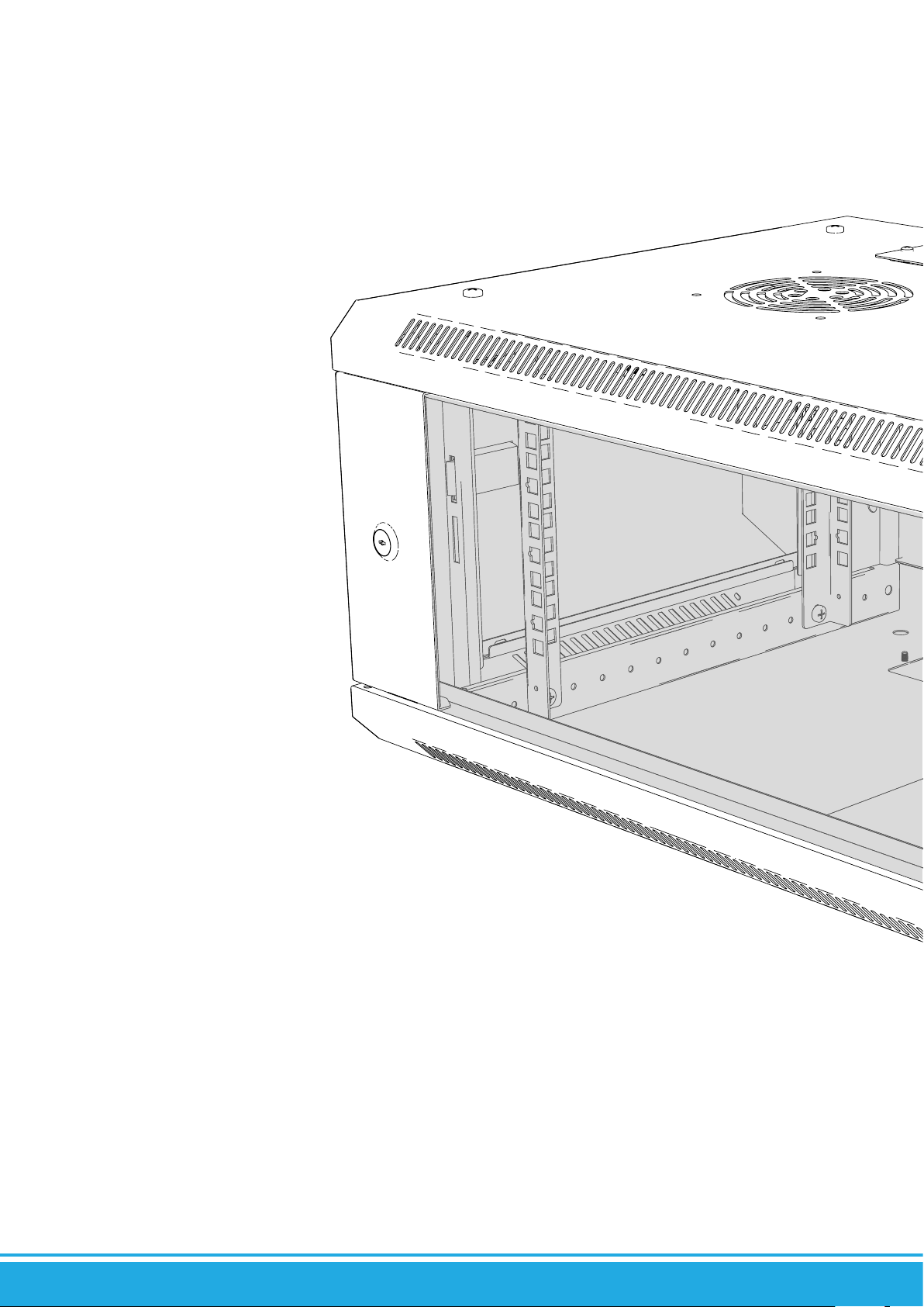
Page 35
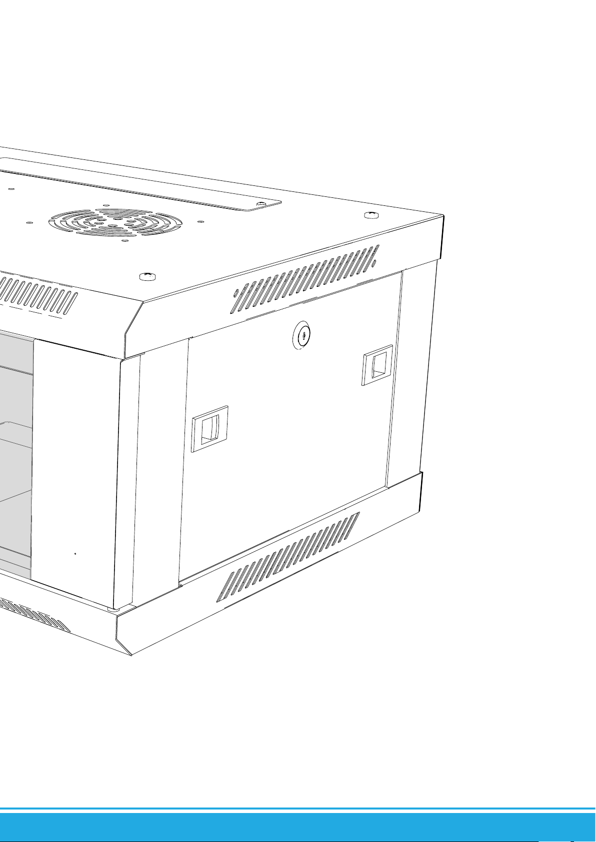
Page 36

 Loading...