

Page 1

Commissioning FMS Firing Management System
TÜV type-approval
0085 AS 0254
DIN DVGW Test mark NG-2510 AS 0324
Sensors and Systems
for Combustion Engineering
Page 2

Table of Contents
2
Access levels 19
General Information 5 - 15
Entering the password 19
Validity of these instructions 5
Changing password 20
Standards 5
Changing parameters 20
For your safety 6
List of parameters
Follow the legislation on safety of appliances 6
(level 0 and 1 parameters only) 21 - 29
Purpose 7 - 8
Leakage test 30 - 31
Intended purpose of FMS 4 / FMS 5 7 - 8
Mode of operation
Application-internal output regulator (optional) 8
Integrated leakage test (option)
Application-internal O regulator (optional) 10
2
Leakage test flow chart 30
Integrated leakage test (option) 30
Using these instructions 9 - 10
Purpose of these instructions 9
Venting
Preliminary clarification 9
Leakage test line over-roof 31
Finding the appropriate section 9
Calculation formula 31
Conventions 9 - 10
Suggested circuit for venting the gas line
Fault correction 10
over-roof in conjunction with the
combustion management system 31
FMS Operating principle 11 - 15
FMS digital inputs 11
Output regulator (optional) 32 - 38
FMS operating sequence 11 - 12
Pre-ventilation suppression
Method of operation 32 - 34
through an external signal 12
Procedure description 32
Automatic pre-ventilation suppression 12
Weather control 32
Setting the pilot burner, serving mode 13
Set-point switch-over 33
Program monitoring time 13
Startup circuit 33
Restarting 13
Thermostat and control region 34
Leakage test (option) 13
Manual control 34
4 curve sets (option) 13
Flying curve change (option) 13
Setting the regulator 35 - 38
Automatic fuel change 13
Interpreting the display 35
Range limits 13
Control region 35
Internal load 14
Regulator behaviour 36 - 38
Manual operation 14
Examples 38
Parameterisation 14
Correction 14
Before commissioning 39
Facility for direct connection
of Namur transmitter (option) 14
Adjusting motor limit switch 39
Freedom from error of feedback signals 14
Pre-ventilation limit 14
FMS Commissioning 40 - 72
Energy-saving mode for running text display 15
Function test 40 - 41
Separate ignition point 15
Significance of FMSdigital input display 41
Integrated power control unit (option) 15
Integrated O regulation 15
2
Setting control elements 42
Operation of control elements for potentiometer
Settings 16 - 30
adjustment and limit switch settings 42
Inputs 16 - 18
Programming curves 43 - 48
Significance of ID number 16
Programming the compound 43
Inputs 16
Entirely new curve, clear memory 43
Configuration sticker 16
st
Programming 1 point
Configuration number 16
(separate ignition point) 44
Condition on delivery 17 - 18
Programming with burner running 44 - 45
Assignment of sockets to inputs 17
Programming with burner stationary 45
Configuration cards (examples) 17
nd th
Programming 2 to 19 point 45
Processor card 18
Programming last top point 46
Power supply card 18
Store curve 46
Plug-in p.c. card for a continuous output 18
Check monitoring values 46
Adding points 47
Parameters 19 - 20
Changing curve point 48
Parameter setting 19
Page 3

Table of Contents
3
Instrumentation for commissioning 72
O regulation 49 - 62
2
Adjusting load ratings individually 73
Automatic functions control
Entering an initial curve 73
during operation 49 - 50
Approaching control elements from one side 74
Adjusting the integrated O regulator (optional) 49
2
Entering settings 74
Checks during burner start-up 49
Entering top setting 74
O monitoring bands 49
2
Ignition delay when setting 74
O boundary curves 49
2
Pre-setting load automatically 74
Dynamic probe test 50
Entering the compound curves
Probe blockage 50
with the burner stationary 75
Correction output monitoring 50
Keeping the re-circulation damper
Regulation strategy 51 - 53
closed in pre-ventilation 75
With pre-setting for load changes 52
Setting the pilot burner (servicing mode) 75
Extended regulation strategy (air shortage) 53
Switching the burner on again
via the target value 75
Connection to O meter 54
2
Via analogue interface 54
Operator controls and display 55 - 56
System Operation 76 - 89
Mode switching 55
Mode display 76 - 78
Calling up O regulation text messages 56
2
Significance of modes on the FMS 76 - 77
O regulator modes 77
Commissioning 57 - 61
2
"ES" Mode progress (set-control) 78
Setting the correction range 57
Continue programming 78
Inputting the O target value curve 58
2
Calling up the correction range set 59
Calculation and setting of
4 Curve sets FMS (option) 79
control parameters-(manual) 59
Interconnection with 4 curve sets option 79
Lag time (parameters 898/900) 60
P-factor (parameter 899) 60
Checksums
Setting base value for "Deactivated
Running time meter 80
control” and "Air shortage” 61
Recalling the checksums
Calling up the base value for O regulation
2
and the safety times 80
deactivated/air shortage 61
Calling up running time meter 80
Automatic 61
Operation 62
Messages / Faults 81 - 89
The meaning of the additional modes 62
What happens in the event of FMS fault 81
Calling up O regulation text messages 62
2
Reading off a fault 81
Resetting a fault 81
Correction 63 - 66
Calling up fault history 81
Set correction input 63 - 65
O regulation perturbed 82
2
Setting the correction range 65
Air shortage perturbation 82
Recall set correction range 65
Resetting O errors 82
2
Altering the correction range 66
Calling up O regulation error history 82
2
Correction modes 66
Fault codes 83 - 89
Run to shut-off limits 67 - 70
FMS Fault Correction
Run to shut-off limits 67
Aids 90 - 115
Checking the shut-off limits at the
General Faults (A) 90 - 94
three/point step output of the FMS 67
Three-point step control output (B) 95 - 96
Checking the shut-off limits at
continuous output of the FMS 68
Continuous output (C) 97
Tolerance limits direction air deficiency 69
Load signal (D) 98 - 99
Indication for an example protocol 69
Feedback (E) 100 - 103
Checking the O influence 69
2
Correction input (F) 104 - 105
Example protocol 70
Digital inputs (G) 106
Control unit faults (H) 107
Tips & Tricks 71 - 75
Leakage test 108
Programming 1st point
(ignition load point) 71
Parameters (P) 109 - 118
Programming with burner running 71 - 72
Programming with burner stationary 72
Reversing the programming 72
Page 4

Table of Contents
4
with leakage test 131
FMS Fault Correction
Oil operation with pilot burner
Aids O regulation 117 - 118
and ignition flame monitor 132
2
Oil poeration without pilot burner 133
Parameter (P) 117 - 118
Relay module R16 134 - 137
Servicing 119 - 120
Circuit diagram type 660 R 0016 V3 134
Changing EPROMs 119
Block diagram type 660 R 0016 V4 135
Changing a data EPROM
Contact plan, relay module type 660 R 0016 V3 136
or a program EPROM 119
Contact plan, relay module type 660 R 0016 V4 137
Re-entering range limits 119
Installing new software version 120
Safety interlock chain 138
Example safetz interlock chain 230V 138
Procedure for installation of
Wiring of the analogue inputs 139
new software in the FMS 120
Replacing the relais module 660 R 0016 120
FMS 4 / FMS 5
Connection diagram 140 - 144
Appendix 121 - 147
Type 664 F 0010 / Type 665 F 0010 140
EMC of wiring 121
Type 664 F 0020 / Type 665 F 0020 141
Connection of screening 121
Type 664 F 0030 / Type 665 F 0030 142
PE bus bar 121
Type 664 F 0040 / Type 665 F 0040 143
Switch cabinet wiring 121
Type 664 F 0050 / Type 665 F 0050 144
Screening of leads from the field 121
FMS 4 / FMS 5
Feedback on TPS channels 122
Connection diagram
Positive connection 122
with output regulator 145
Example of positive
potentiometer connection 122
Direct connection of
Error-proof feedback 122
Examples of potentiometers 122
Namur transmitter (option) 146 - 147
Examples of servomotors 122
Extract from circuit diagram 146
External switching of the fuel control element 123
Technical data 146
Selecting a suitable sensor
for rev. speed monitoring 147
Replacing a servomotor,
replacing a potentiometer 124 - 125
Relay module
Replacing a servomotor with LAMTEC
connection diagram 148
precalibration 124
Type 660 R 0013 / Type 660 R 0131 148
Replacing a complete servomotor 125
Type 660 R 0019 148
Replacing the potentiometer in a servomotor 125
Connection diagram
Switch and key combinations
Modem for remote control 149
on the VMS / FMS front panel 126
Switch and key combinations
General Notes 150
O regulation 127
2
Technical data 151 - 152
Notes on air pressure monitor
Accessories
Not on operation with
and Spare Parts 156 - 157
re-circulation control elements 128
Accessories and Spare Parts for
Interconnection of the air pressure monitor 128
FMS Combustion Management System 156 - 157
Paramterisation of the
re-circulation pre-ventilation time 128
Interconnection of monitors
Declaration of Conformity 158 - 159
of the re-circulation ducts 128
EC Declaration of Conformity 158
Notes on start without pre/ventilation 129
Appendix to the EC Declaration of
Conformity or EC Manufacturer's Declaration 159
Process sequence charts 130 - 133
Gas operation with pilot burner,
Protocol example 160
leakage test and ignition flame monitor 130
O target value curves 161
2
Gas operation without pilot burner
Page 5

5
General Information Validity of these Instructions
Validity of these instructions These instructions apply to the FMS 4 and FMS 5 Combustion Management
System in any configuration.
The software-related information relates to the software version V3.1
(recognisable from the sticker inscription on the program EPROM).
Standards The units conform to the following standards and regulations:
FMS EN 298
EN 230
where applicable
where applicable
where applicable
where applicable
EMC Directive, Low Voltage Directive
Gas Appliance Directive
Integral leakage test:
EN 1643
Test mark
gas side DIN DVGW PÜZ NG-2510 AS 0324
CE-0085 AS 0254
EN 676
EN 267
EN 12 952-8 u.-11
EN 12 953-7 u.-9
Page 6

6
General Information For your safety
Follow the legislation The legislation on safety of appliances states:
on safety of appliances Follow the instructions !
Proceed only in accordance with this FMS commissioning supplement
(booklet No. D LT 6079)
Use the appliance solely for the specified purpose.
It must be operated only by trained personnel. The appliance must be
operated and serviced only by persons with the required knowledge and
training. Follow the burner manufacturer's safety rules.
Associated automatic flame guard
The unit is approved for use only with an external automatic flame guard.
The automatic flame guard type F 250 made by Hartmann & Braun is used
for testing purposes.
However, any other automatic flame guard tested in accordance with
DIN EN 298 and/or DIN EN 230 and approved for continuous operation may
be used instead of this.
Electrical connection to appliances not mentioned in these instructions
Only after consultation with the manufacturers or a qualified expert.
If an automatic flame guard not approved for continuous operation is
connected, approval of the system for continuous operation will lapse.
Liability for proper functioning of the appliance passes to the owner
or operator.
Liability for correct functioning of the appliances in every case passes to the
owner or operator, should the appliance be incorrectly operated, serviced or
repaired by persons without the requisite knowledge, or if operation is
inconsistent with the specified intended purpose.
In the event of modifications to the unit the type approval lapses. The unit's
inputs and outputs and associated modules must only be wired according
to the specifications in these instructions.
LAMTEC GmbH & Co KG will not be liable for damage or injury arising out of
a failure to observe the instructions above. The warranty and liability provisions
of the terms and conditions of sale and supply of LAMTEC GmbH & Co KG
shall not be extended by virtue of the instructions above.
Where reference is made to legislation, government regulations and
standards, these are based on the legal system of the Republic of Germany.
To be used only in a grounded power line network!
Page 7

7
General Information Purpose
Intended purpose The FMS 4 / FMS 5 Combustion Management System is a control unit for
FMS 4 / FMS 5 combustion systems.
Brief description
The FMS 4 adjusts up to four control elements as a function of a control
variable (generally the burner load) according to freely programmable
curves.
The FMS 5 adjusts up to 5 control elements as a function of a control
variable according to freely programmable curves).
2 sets of curves (e.g. for oil or gas) can be filed as standard, with the
option for 4 or 8 sets of curves.
Examples of possible control elements:
- Combustion air damper - Re-circulation fan
- Combustion air fan - Flue gas damper
- Fuel quantity - Flue gas fan
- Atomiser steam
Up to 20 points can be programmed for each channel. The display is
relative between 0 and 999.
The FMS has two correction inputs for shifting the setting curves, allowing
a feedback control (e.g. O control unit) to be connected up.
2
Each output is freely configurable, either three-point step control element
output for direct actuation of a motor or constant output (on the FMS 5
th
the 5 channel is always constant). The constant output can be set to any
of the following variables:
- Current signal 0 … 20 mA
- Current signal 4 … 20 mA
- Voltage signal 0 … 10 V
The FMS 4 also has a so-called monitor output. In addition an internal
value (such as the load position of the burner or position of the gas control
element) can be outputted by means of 4 … 20 mA signal).
The FMS has one serial interface for remote control/ display via PC
(Windows software available separately) and for connection to other
system components via BUS (e.g. fault message system, O control).
2
Connections for Interbus-S, Profibus, Modbus and CANBUS are available as options. Other BUS systems on request.
The FMS constantly monitors its own functioning and that of the control
elements connected.
Each analog input (control variable and feedback or correction) is freely
configurable via plug-in cards.
Alternatively:
- Potentiometer (1 5kS) - Step input (DPS)
- Current signal 0/4 … 20 mA - Namur transmitter as a two-wire system
- PT 100 - inductive sensor with switch terminals in
three-wire system
The unit is of error-proof construction.
Page 8

General Information Purpose
Application - internal
output regulator
(optional)
Application - internal
O regulator
2
(optional)
The FMS contains a burner control unit with process control program.
Outputs:
- actuation of gas valves
- actuation of oil valves
- actuation of the ignition valve and ignition transformer
- fan release
- oil pre-heating
- fault signal
- signal outputs for oil and gas operation
(in the off condition, oil operation is always indicated)
The external signals to the control unit are via floating contacts or chains of
contacts.
The following signals can be pre-set:
- 3 separate safety interlock circuits
- fault unlocking
- air pressure monitor
- gas pressure monitor (min.)
- flame signa
This software option makes it possible to calculate the burner's required load
setting continuously for a specified target value (referred e.g. to temperature or
pressure), through comparison with the actual value. This load setting can be
notified internally to the electronic compound as the specified value.
This software function makes it possible to regulate one or several actuators
independently of a switched-on O actual value. By using a self-optimising
2
regulator strategy, it is also possible to regulate burners with frequent load
changes.
l (pilot flame monitor and ignition flame monitor)
- pre-ventilation and ignition release
- pre-ventilation suppression
- control release
- re-circulation release
- burner on
- fuel selection
8
Page 9

9
General Information Using these instructions
Purpose of these instructions These instructions are concerned exclusively with commissioning and
servicing.
Further information, for example design examples, possible uses, software
settings etc., is given in separate booklets.
Special information dealing with optional equipment on this unit is
explained in separate booklets.
Preliminary clarification To make the best use of these instructions, proceed as follows:
Check whether the settings of your FMS meet the system requirements.
You will find the settings on the sticker on the unit.
- Which physical quantities (current, resistance) and values does your
FMS need on its inputs?
- Which physical quantities (current, voltage, relay signal) and values
does the system expect on the outputs of the FMS ?
- Do the settings of the FMS match your requirements with regard to
operating behaviour (pre-ventilation, feedback etc) ?
Should these matters not be clear, please read the section "Settings”
(page 16-29)
Finding the appropriate section Determine what operation you wish to perform on the FMS.
When initially putting into operating or tracing the cause of a fault, a
function test is first recommended. You must then decide whether you
wish to program with the burner stationary or running and whether or not an
entire curve is to be programmed.
Identify your current requirement from the table of contents and turn to the
appropriate page.
Conventions Sub-headings
Serve as a guide if you can already handle the FMS and merely want to
refer to certain information again.
Lines in italics after the sub-headings
describe what the current state of the system should be. If this is not the
case, the subsequent operations will not show the desired result.
Lines in bold type
indicate an action which you are to perform.
Page 10
10
General Information Using these instructions
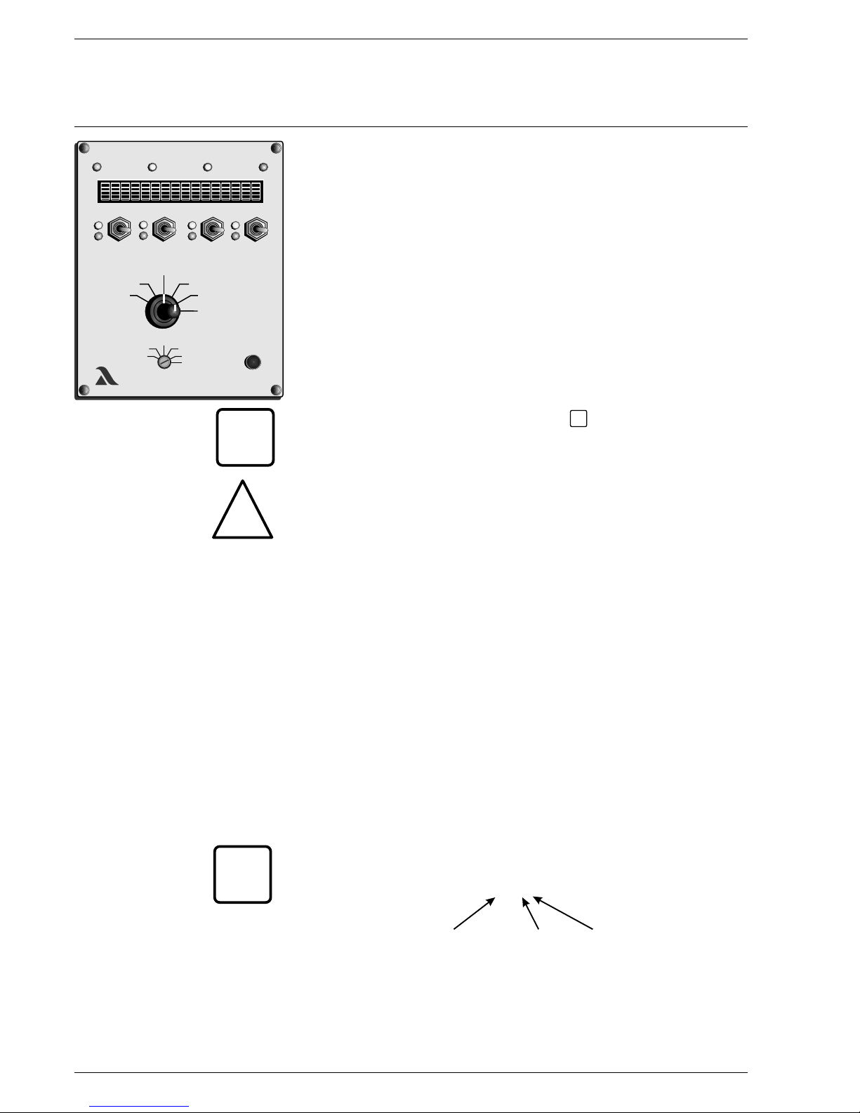
The figures and letters in brackets (1), (2), (3), (4), (5), (6), (7), (8), (A)
and (B) relate directly to the picture of the front panel. They identify the
part on which the specified action is to be performed or on which a reaction
can be seen.
The lines in ordinary typeface below the procedural instruction describe
the reaction of the system or unit following the operation.
The figures at the right-hand margin denote a paragraph in the
"Fault Correction” section of these instructions. If the reaction indicated
does not occur, please refer to this. It describes the possible causes of
faults and how to rectify them.
___________________________________________________________________
The word in italics between two lines and the sign
are notes for a better understanding of the operation or notes on how to
avoid incorrect operation.
___________________________________________________________________
___________________________________________________________________
The lines in bold italics between two lines and the triangle
draw attention to dangers. The instructions given there must be followed.
___________________________________________________________________
If you now follow the operations step by step, paying attention to the
instructions, you will automatically be working correctly.
If any of the reactions indicated do not occur, there is a fault with the unit or
the system. You should correct the fault first before proceeding.
Fault correction Follow the instructions identified by the figures given after the fault codes
and after the procedural instructions. You may find the solution to your
problem there.
This section, however, makes no claim to completeness. Should the
actions described there not have the desired effect, the unit or parts of the
unit (e.g. front panel etc.) must be changed. If the fault still occurs you are
dealing with a fault specific to the system.
___________________________________________________________________
Tip: You can download the up-to-date version of these instructions from
http://www.lamtec.de as PDF File.
You will find the version from the letter of the booklet no.
(see the backside of this document).
Example:
DLT 6066 cD
booklet No. version language
___________________________________________________________________
CHANNEL 1 CHANNEL 2 CHANNEL 3 CHANNEL 4
ENTER
POWER OIL GAS ALARM
SETPOINT
FEEDBACK
SETPOINT
FEEDBACK
ACTUAL VALUE
FEEDBACK
ACTUAL VALUE
FEEDBACK
SETPOINT
CHANNEL 5
xxx
xxx
xxx
5
4
6
A
B
7 8
3
SETTING
AUTOMATIC
CLEAR
MEMORY
O -CONTROL
2
PARAMETERISATION
MONITORIN
DISPLAY
FEUERUNGS-MANAGEMENT-SYSTEM FMS
LAMTECLAMTEC
xxx
2
1
DISPLAY CHANNEL 5
(DIGITAL INPUTS)
LOAD RATING
(CORR. INPUT)
STATUS
(CORR. RANGE)
SETPOINT
ii
i
!
i
Page 11

11
General Information FMS Operating Principle
FMS Digital Inputs For the FMS to function according to the requirements of a combustion
system, the condition signals from the system must be relayed to the FMS.
These signals include:
Pre-ventilation suppression Air pressure monitor
Gas safety interlock circuit Gas pressure > min.
Oil safety interlock circuit Ignition flame
Boiler safety interlock circuit Burner on
Ignition position acknowledgement Fault reset
High firing rate acknowledgement Re-circulation On
Fuel selection Control release
Flame signal Set-point switch over
(only with integral load control unit)
For use in burner control, the FMS emits 9 digital signals, which are
converted by relay module (type 6 60 R 0016) into twelve output signals
for 230 V:
Main gas 1 Ignition valve
Main gas 2 Ignition transformer
Oil Release ignition gas line
Heated oil distribution Fan
Oil operation signal Pre-ventilation / post-ventilation
Gas operation signal Fault signal
___________________________________________________________________
FMS operating sequence The operating sequence described relates to a usual configuration of the
(for diagram of example, unit. The various parameter settings can result in a somewhat different
see appendix) sequence.
___________________________________________________________________
A signal is first sent to terminal 2 (burner ON), indicating when the burner is
to start. The FMS then interrogates the safety interlock chain for the
selected fuel and the air pressure monitor contact. If the fuel is selected via
the fuel safety interlock circuits, the FMS performs a plausibility check. If it
does not detect a satisfactory condition, a corresponding text message is
emitted and the process control stops.
If all signals are OK, the fan output is activated and the ducts run to their
bottom stop as a check. The "pre-ventilation/post-ventilation” output is
activated. Once all ducts have reached their bottom stop, they open for
aeration. Any leakage test configured runs in parallel.
In the case of control elements, aeration is used to enter and to check the
range limits. The fuel control element, after reaching its top position, runs
back into the ignition position. All other ducts remain in the open position.
The FMS now interrogates the high firing rate acknowledgement and the air
pressure monitor. If these signals are OK, the parameterised aeration time
runs. If a duct is configured for re-circulation, this opens with a time delay.
On reaching the parameterised re-circulation delay time, the pre-ventilation
time stops. As soon as the re-circulation duct has reached the aeration
position, the aeration time continues. Once this time has elapsed the
ducts run into the programmed ignition position (re-circulation fully
closed). Once all ducts have reached ignition position, the FMS
interrogates the ignition position acknowledgement. In gas operation the
gas pressure monitors must also be in a satisfactory condition prior to
ignition.
The ignition transformer is now activated alone for the duration of the
pre-ignition time (transformer start-up time).
Page 12

12
General Information FMS Operating Principle
Start without pilot burner:
The main valves open and remain activated together with the ignition
transformer for the duration of the safety period. During this time the flame
signal appears.
Start with pilot burner:
The ignition valve and main gas 1 are opened. The pilot flame forms and
st
the flame signal appears. Once the 1 safety period has elapsed, the pilot
burner burns on its own. The main gas 2 then opens and remains activated
nd
in parallel with the ignition valve for the duration of the 2 safety period.
When this period has elapsed the ignition valve closes again.
When ignition is completed the re-circulation duct and the flue gas damper
run to the programmed point. Correction is activated. All ducts may run to
the programmed base load point (depending on the setting selected).
The FMS remains in the base load position until control release (terminal 4)
is given.
Following control release the FMS follows the prevailing external load.
A current signal proportional to the position of the compound is emitted as
internal load (not on FMS 5).
Withdrawal of the signal/control release during operation allows the
compound to run at base or ignition load (configurable).
Withdrawal of the terminal 2 signal is followed by shutting off. The main
valves close. (In gas operation, main gas 1 first, followed by main gas 2
with an approx. 5-second delay, in order to allow the monitoring line
between the solenoid valves to burn out. In the event of a fault shut-off,
however, they both close immediately).
If configured for post-ventilation, the air ducts open again for this period.
After the configured after-burning time the FMS again checks for a period
of 5 seconds whether the flame has gone out. If not, a fault shut-off
occurs.
The FMS then goes into "OFF” mode.
Pre-ventilation suppression The pre-ventilation range can be skipped by means of the pre-ventilation
through an external signal suppression signal (terminal 1). If the signal is present straight away at
burner start-up (terminal 2 signal), the control elements run directly to the
ignition position. In order to enter the range limits, however, pre-ventilation
should be performed once after "Clear Memory”.
Pre-ventilation suppression can only occur, however, if this function is
activated via parameters.
Automatic pre-ventilation When activated by parameters, the FMS starts after regulator switch-off
suppression automatically without pre-ventilation. Pre-ventilation is only carried out now after
fault switch-off or power failure. Using this function is subject to the regulations
applicable to the facility.
Page 13

13
General Information FMS Operating Principle
Setting the pilot burner,
servicing mode
Program monitoring time
Restarting
Leakage test (option)
4 curve sets (option)
Automatic fuel change
Flying curve change
(option)
Range limits
A so-called servicing mode can be set via parameters. The control unit then
runs until the stabilisation period. In this mode 5 successive starts are
possible without the need for pre-ventilation and without a leakage test.
th
The 5 start is automatically followed by pre-ventilation and/or a leakage test.
It can be determined by way of parameters how long the FMS may take
after a start signal (terminal 2) until ignition occurs. If this length of time is
exceeded, a fault shut-off occurs. If the content of the parameter is set to
0, no fault occurs (= program monitoring time = T).
Automatic restart can be activated via parameters. The control unit attempts
a one-off restart in the event of any fault marked with * after a factory-set
period (standard: 10 sec). This restart can be prevented by setting the period
to 0.
n the case of firing systems according to EN 676 the parameter must
be set to "0”.
The standard setting is without restart.
The control unit may optionally also perform the leakage test on the gas
valves. The leakage test can per performed before ignition and/or after
shut-off
The leakage test is performed by way of the main valves. The use of filling
and discharge valves is also possible by means of relay switching.
The FMS offers the facility for using two curve sets for each fuel
(e.g. summer/winter operation) or a mode with and without speed.
When using Option 4: Curve sets, it is possible to switch within one fuel
selection from one curve-set to the other (flying curve change). Fuel
change can only be performed via "Off”.
When switching the fuel selection switch over (terminal 75), the FMS first
moves automatically to the base load position. Then the system switches
off. Only then are the fuel selection and thus the curve set changed over. If
the "Burner on” signal is still present, the burner starts with the new fuel.
(This function is not available with Option 4: Curve sets).
st
In the 1 pre-ventilation after "Clear memory”, the FMS determines the
maximum range of travel for each control element and stores this
automatically. If no ranges limits have yet been determined, the setting (in
the case of constant outputs the feedback setting) in pre-ventilation
stands at 0 and 999 points respectively. At all further starts a check is
made to see that these range limits are correct. Should the limit switches
be shifted or the frequency converter setting changed after programming,
the range limits must be re-entered.
If the range limits cannot be determined automatically, they can also be
entered manually by way of parameters. If the FMS has no existing range
limits, it automatically takes the top and bottom point of the curve as the
limit. It then does not go beyond this.
____________________________________________________________
I
____________________________________________________________
!
Page 14

14
General Information FMS Operating Principle
The internal load is the load value at which the compound currently stands.
It therefore corresponds indirectly to the output of the burner.
The internal load is displayed in addition to the external load signal.
In the "load value” position therefore both the external load (left-hand) and
the internal load (right-hand) are displayed.
The value of the internal load can be outputted via the monitor output, in
order to connect further units (e.g. O control, only on FMS 4). When
2
connecting other units, it must be remembered that the signal in itself is
not error-proof.
When switching over to "Load value” with the burner running the burner
load can be set via the FMS. The load value can then be adjusted with the
channel 1 toggle switch.
The system follows this load value in the compound.
Operating a switch other than channel 1 causes the unit to exit manual
mode again.
The person commissioning the unit can adjust various functions of the
FMS
by way of parameters (e.g. post-ventilation time). The parameters are
classified into various safety levels. With the exception of the lowest safety
level these are accessible only with a password. The parameterisation can
be undertaken both on the unit itself and by means of a PC and Windows
software.
The FMS has 2 correction inputs. An analog signal (0/4 … 20 mA) can be
connected to these for shifting the set curves (e.g. for O correction or air
2
temperature correction). The assignment of the correction to the individual
output channels and the mode of operation can be adjusted via
parameters.
If the FMS cannot perform a correction because a control element stop has
been reached, it adjusts the internal load and hence the compound until
the correction can take effect as required.
An output for controlling the speed of a combustion air fan or a
re-circulation fan etc. can be monitored by switching the pulse output of a
Namur transmitter directly to the FMS.
Continuous outputs and three-point step outputs have different feedback
requirements. In the case of continuous outputs comparisons are made
between output and feedback values in or to check the plausibility. The
units therefore do not have to be intrinsically error-free in order to form the
feedback signal. For availability reasons (minimisation of interference) the
reproducibility of the values should be as good as possible.
For technical reasons this method cannot be used in the case of
three-point step outputs. For this reason TÜV approved potentiometers
must be connected directly as feedback to the FMS. These
potentiometers must positively render the position of the damper.
Normally during pre-ventilation each control element runs as far as ist
uppermost stop. Now, by means of parameters, a limit can be set for each
channel that is not exceeded during pre-ventilation.
Internal load
Manual operation
Parameterisation
Correction
Facility for direct connection
of Namur transmitter
(option)
Freedom from error
of feedback signals
Pre-ventilation limit
Page 15

15
General Information FMS Operating Principle
Energy-saving mode for The brightness of the display can be adjusted to the ambient light
running text display conditions by means of parameters.
In addition the display can be set to automatically revert to the lowest
brightness level if not operated within a given period of time.
Separate ignition point In the standard version the ignition point is situated outside the accessible
range in order to set a separate fuel/air ratio. By means of parameters,
however, the ignition point can be adjusted so that it lies on the compound
curve.
Integrated power control unit An integrated power control unit is also available as an option. Where this
(option) is used the actual temperature or the actual pressure is directly switched
instead of the load signal. The control parameters are adjusted via
parameters. It is also possible to change the setting (daytime/night time
The integral output regulator is a PID controller with special combustion
technology functions. It can be used as a fixed-value regulator or as a
weather-dependent regulator. The following signals can be set:
- Actual value (analogue)
- External temperature or some other analogue signal for target value shifting
(only in weather-dependent regulators)
- Target value switching (via zero-potential contact)
Combustion enabling by the output regulator takes place internally in the FMS
Boundary values that switch the burner on and off, need to be set via parameter
regulation - optimises combustion systems
2
- saves fuel
- minimises pollutants
The main purpose of O regulation is to compensate for perturbations that
2
affect combustion. In addition, the O regulation system monitors the
2
combustion's fuel/air ratio. A message is output at once if it strays outside
the permitted limits.
The following are the main perturbing factors that affect combustion:
Air: Temperature Contamination: Burner
Pressure Boiler
Humidity
Fuel: Calorific value Mechanical systems:
Temperature Mechanical
Viscosity hysteresis
Density (free play)
Gas pressure fluctuations
The O control unit is implemented as a free-standing software module.
2
The unit compares the residual oxygen content in the exhaust gas of a
combustion system measured by means of the LT1/LT2 Lambda
transmitter (actual value) with the optimum residual oxygen content (target
value). The target values are stored in the instrument in the form of an
installation-specific curve. The control unit applies a correction until the
actual value corresponds to the target. The calculated output value of the
O control module is transmitted to the compound module as a correction
2
input signal.
operation) and to control the atmospheric conditions by switching in the
outside temperature.
setting. In this case, the startup signal is removed internally from the FMS via the
output regulator module.
The operator is alerted by the display (running text) that the output regulator
refuses to enable a startup.
Integrated O
Page 16

16
Settings Inputs
Significance of ID number The ID number comprises 8 characters, e.g. 664 V 0010
The two figures before the letter denote the unit, in this case a FMS 4.
The letter denotes whether the unit is a VMS or a FMS. The penultimate
figure provides information on the unit hardware.
It also determines which connection diagram applies (see appendix).
Inputs The inputs can be configured on the backplane by means of plug-in
configuration cards. Any of the following can be connected up to each
input:
- a potentiometer in the range from 1-5 kS
- a current signal 0 … 20 mA or 4 … 20 mA
- a step signal ("OPEN CLOSE" commands)
- a frequency signal (Namur transmitter), for details see appendix
- a PT 100 element
- flame sensor module (in preparation)
- a potentiometer module (in preparation)
There is a plug-in card for each configuration. This is inserted into the
respective socket in order to configure the input.
Configuration sticker The factory setting is entered on a sticker on the side of the unit.
This corresponds either to the customer data or, if nothing was specified,
the standard setting (see condition on delivery).
The EEPROM checksums and thereby the software version are also
entered on this sticker, together with the configuration number and hence
the hardware setting.
Configuration number The configuration number is a 15-digit number, constructed according
to a fixed code.
BUS-card
input voltage
Channel 1 assignment
red. feedback channel 4
red.
red.
red.
Correction input 1
Channel 5 feedback
Load input
Channel 2 assignment
Channel 3 assignment
Channel 4 assignment
Channel 5 assignment
feedback channel 3
feedback channel 2
feedback channel 1
Correction input 2
Channel 4 feedback
Channel 3 feedback
Channel 2 feedback
Channel 1 feedback
a x b x x x x x c x x d x x x x e x f x K y y y y y
BUS-card
x = 1 ^ Interbus-S
2 ^ SUCOnet K-Bus
3 ^
4 ^ Profibus
5
0 ^ not present
CAN-Bus
^ Modbus
K = Channel assignment
y = 1 ^ Recirculation
2 ^ Fuel
3 ^ Air
4 ^ Flue gas
5 ^ mech. Compound
6 ^ Steam
a, b, c or d =
Feedback, correction and load
x = 1 ^ Potentiometer input 1kW...5kW
2 ^ continuous signal 0/4...20mA
3 ^ TPS input
4 ^ Pulse input (Namur)
5 ^ PT 100-input
6 ^ Flame sensor input
(only on red. feedback channel 4)
7 ^ continuous signal 0/4...20mA
potential separated
8 ^
0 ^ unoccupied
constant signal with 24 V supply
Input voltage
x = 1 ^ 230 VAC
2 ^ 115 VAC
3 ^ 24 ACV
4 ^ 24 VDC
5 ^ Special voltage
Page 17

Settings Condition on delivery
Condition on delivery All units are set according to the order. Settings not evident from the
ID number or configuration number must be indicated separately.
In particular:
Outputs
- whether continuous or three-point step
- whether 0 … 10 V, 0/4 … 20 mA
- position of the outputs in the event of fault
Inputs, load, feedback
- Whether potentiometer or 0/4 … 20 mA or step
- Whether inputs are used doubled (redundant) and if so, which
(possible only if the integrated power control unit is not used)
- Whether special plug-in configuration cards
(PT 100, Namur transmitter) are used
Correction input
- Whether 0 … 20 or 4 … 20 mA or direct temperature connection
- Mode of operation, on which channel, upward or downward shift
(modifiable only via software)
Assignment of Backplane
sockets to inputs
Configuration cards
(examples)
Feedback 1
Corr. Input 1
Corr. Input 2
Load input or load
control unit value
Feedback 2
Feedback 3
Feedback 4
Feedback 5
Red. Feedback 1
Red. Feedback 2
Red. Feedback 3
Red. Feedback 4
or atmosphere control
or flame sensor module
17
R4 = 0W
R4 = 0W
R4 = 0W
R8 = 2K2
R10 = 2K2
R15 = 0W
R12 = 0W
R12 = 0W
R11 = 0W
R16 = 0W
R17 = 0W
R15 = 0W
Potentiometer
Configuration
TPS
configuration
0/4 … 20mA
configuration
TM1
R17
R18
R16
R13
R14
R15
R5
R11
R12
R10
R7
R9
R8
R4
D1
T1
C1
R6
R2
R3
D2
R1
D2
D1
R10
R12
R16
R4
R15
R8
R11
R18
R9
R7
R13
R14
R17
R1
R3
R5
R2
R6
C1
TM1
T1
TM1
R10
R12
R11
R5
R16
R18
R17R13
R15
R14
R9
R7
R4
R8
R2
R6
C1
T1
D1
D2
R3
R1
Page 18
Settings Condition on delivery
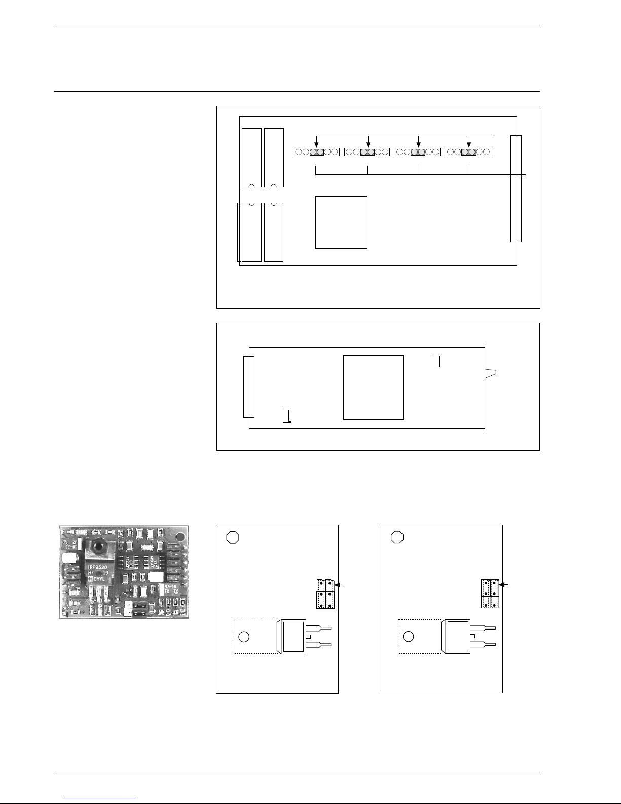
Processor card
Note:
Continuous channels must all be fitted with additional cards from
channel 1 onwards
Power supply card
Plug-in p.c. card for The standard control outputs are three-point step
a continuous output (except for a possible 5-channel. This is always continuous).
Each TPS output can be reconfigured to make it continuous by plugging in
an additional card.
The jumpers serve only for hardware switching between current output
and voltage output.
The selection of 0 or 4 … 20 mA is done through the software by means
of parameters.
18
T 902
EEprom for curves
and parameters
Monitoring processor
EEprom for curves
and parameters
Main processor
Program processor
Main processor
Program EPROM
Over-voltage
processor
Sockets for contiuous additional cards
TPS
Configuration
Channel 1
Transformer
Fuse 2
1 AT mA
80 C 537
Channel 2 Channel 3 Channel 4
Bridge
voltage
output
0 … 10V
Bridge
current
output
0/4...20mA
T 902
Page 19
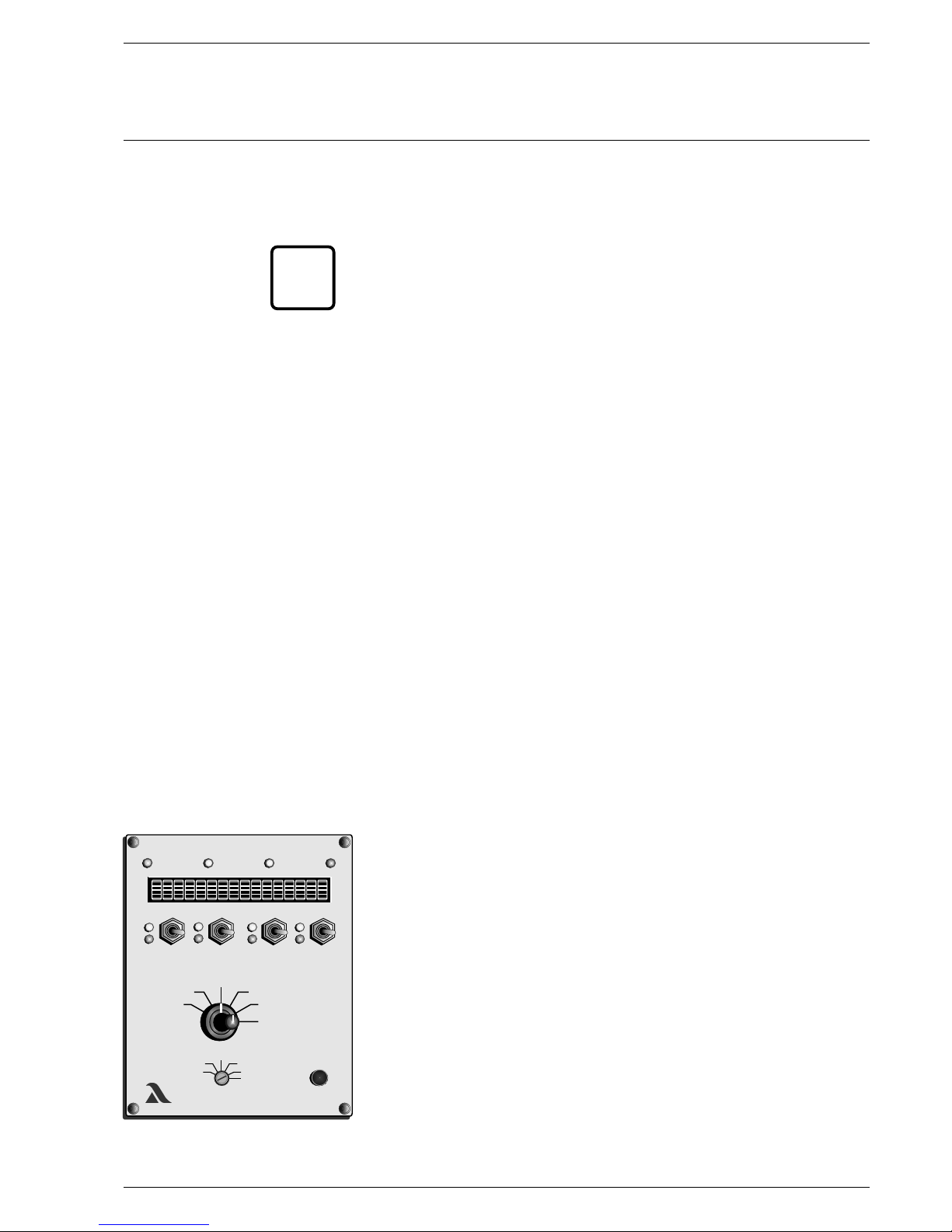
Settings Parameters
Parameter setting The parameter level can be accessed by turning to the "Parameter”
selector switch position. When working on level 1-4, this works only with
the burner stationary (i.e. no signal on the digital inputs). Only level 0 is
accessible with the burner running.
___________________________________________________________________
As a rule, the factory parameter settings are precisely tuned for the
installation for which the unit has been designed. Therefore, it is only
necessary to change parameter settings in exceptional cases.
___________________________________________________________________
Access levels The parameters are divided into four different access levels according to
function and safety classification:
Operating level (Level 0)
! Accessible without password, non-critical parameters that may possibly
have to be altered during operation.
Customer level (Level 1)
! Accessible with modifiable password (on delivery set at "0000”), access
to parameters, adjustment of which calls for technical knowledge, which
are tailored to the system and which are not altered during operation.
Service level (Level 2)
! Accessible with a fixed password, but only to personnel specially trained
in parameterisation. Access to all parameters that are not fixed on the
basis of standards and technical regulations.
Production levels (Levels 3 and 4)
! Access to all parameters (only possible through LAMTEC)
Each parameter level is protected by its own checksum. This checksum
serves to show that no changes have been made (see page 78).
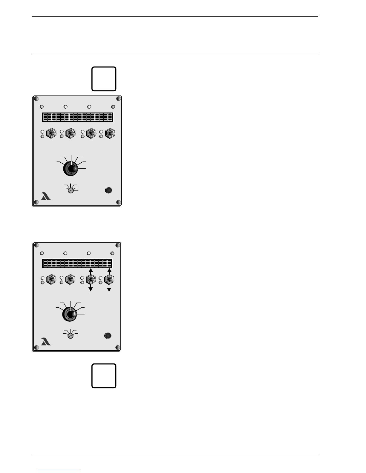
Entering the password Selector switch (1) to status
Push switch (4), channel 2 and 3, up
and at the same time
push switch, channel 4, down
- the input field for the password appears on the display.
Set the appropriate password via the switch.
Acceptance key (3)
Parameters on the corresponding level are released.
Selector switch (2) to parameterisation
xxx
LAMTECLAMTEC
xxx
xxx
xxx
2
3
4
1
19
!
!
!
i
Page 20
Settings Parameters
Changing the password ____________________________________________________________
Only possible at customer level (level 1)
____________________________________________________________
From level 1, once accessed:
Turn selector switch (1) to Status
Simultaneously push keys (4) channel 2 and 3 upwards
and channel 4 downwards
- the display shows the password input field
Set the new password for the level
Turn selector switch (1) to Digital inputs
Press the Acceptance key (3)
- new password is set
Changing parameters Select the required parameter with Channel 3 key
Change its value with Channel 4 key
- The values are accepted immediately without further confirmation
An explanatory text for the parameters can be called up by pressing
the Acceptance key (3)
____________________________________________________________
For larger values, changes can be in x100 steps with Channel 1 key and
in x10 steps with Channel 2 key.
____________________________________________________________
xxx
LAMTECLAMTEC
xxx
xxx
xxx
3
4
1
20
i
xxx
LAMTECLAMTEC
xxx
xxx
xxx
3
i
Page 21

Settings List of Parameters
(Level 0 and 1 parameters only)
_____________________________________________________________________________________________________
Para- Short Safety Lower Upper
meter- design- level limit limit Standard
No. nation Description values Aids
_____________________________________________________________________________________________________
Pre-ventilation
346 VO LimK1 1 0 999 Limit to which pre-ventilation can be 999 P4
terminated, Channel 1
347 VO LimK2 1 0 999 Limit to which pre-ventilation can be 999 P4
terminated, Channel 2
348 VO LimK3 1 0 999 Limit to which pre-ventilation can be 999 P4
terminated, Channel 3
349 VO LimK4 1 0 999 Limit to which pre-ventilation can be 999 P4
terminated, Channel 4
350 VO LimK5 1 0 999 Limit to which pre-ventilation can be 999 P4
terminated, Channel 5
Running direction
374 Laufr.K1 1 0 999 Channel 1 running direction in event or fault 2 P6
375 Laufr.K2 1 0 15 Channel 2 running direction in event or fault 2 P6
376 Laufr.K3 1 0 15 Channel 3 running direction in event or fault 2 P6
377 Laufr.K4 1 0 15 Channel 4 running direction in event or fault 2 P6
378 Laufr.K5 1 0 15 Channel 5 running direction in event or fault 2 P6
427 Vodel R 1 0 999 750 P71
When changing the parameters via interface (by means of optional PC software) a check must then be made on
the spot to ensure that the changes have been properly accepted. This can be done by reading out the
parameters on the unit or by comparing the unit's checksums. See page 78 .
0 = OFF (control element stops)
1 = Control element runs OPEN
2 = Control element runs CLOSED
3 = Control element runs to the setting
6 = Control element runs to its ignition point
8 = Control element runs to base load
Re-circulation delay time (on FMS)
No. of air duct points (VMS)
21
Page 22

22
Settings List of Parameters
(Level 0 and 1 parameters only)
Para- Short Safety Lower Upper
meter- design- level limit limit Standard
No. nation Description values Aids
_____________________________________________________________________________________________________
Correction
433 K1 Spreiz 1 0 999 10 P22
434 K2 Spreiz 1 0 999 10 P22
517 KB11.1 0 0 999 0 P7
597 KB21.1 1 0 999 0 P7
Monitor output
677 Moni.1 1 0 23 0 P8
678 Moni.2 1 0 25 0 P9
679 Moni.3 1 0 25 0 P9
3
680 Moni.4 1 0 25 0 P9
4
681 Moni.5 1 0 25 0 P9
5
682 Moni.6 1 0 25 0 P9
6
683 Moni.7 1 0 25 0 P9
7
684 Moni.8 1 0 25 0 P9
8
685 Unt.Mo1 1 0 999 0 P10
686 Unt.Mo2 1 0 999 2: 0 P10
687 Unt.Mo3 1 0 999 3: 0 P10
688 Unt.Mo4 1 0 999 4: 0 P10
Spread factor for correction input
(00.0 99.9) 01.0 = no expansion
Spread factor for correction input
(00.0 99.9) 01.0 = no expansion
Correction range, correction input 1
Correction range, correction input 2
Definition of the monitor output
with curve set 1
0= internal load 14= channel 4 actual value
1= channel 1 setting 15= channel 5 actual value
2= channel 2 setting 21= external load
3= channel 3 setting 22= correction input 1
4= channel 4 setting 23= correction input 2
5= channel 5 setting 24=O -actual value
2
11= channel 1 actual value 25=O -setpoint
2
12= channel 2 actual value 26=Flame intensity
13= channel 3 actual value
Definition of the monitor output
with curve set 2
Definition of the monitor output
with curve set
Definition of the monitor output
with curve set
Definition of the monitor output
with curve set
Definition of the monitor output
with curve set
Definition of the monitor output
with curve set
Definition of the monitor output
with curve set
Monitor output, curve set 1:
4 mA correspond to X points
Monitor output, curve set
4 mA correspond to X points
Monitor output, curve set
4 mA correspond to X points
Monitor output, curve set
4 mA correspond to X points
Page 23

Settings List of Parameters
(Level 0 and 1 parameters only)
Para- Short Safety Lower Upper
meter- design- level limit limit Standard
No. nation Description values Aids
_____________________________________________________________________________________________________
689 Unt.Mo5 1 0 999 Monitor output, curve set 5: 0 P10
4 mA correspond to X points
690 Unt.Mo6 1 0 999 Monitor output, curve set 6: 0 P10
4 mA correspond to X points
691 Unt.Mo7 1 0 999 Monitor output, curve set 7: 0 P10
4 mA correspond to X points
692 Unt.Mo8 1 0 999 Monitor output, curve set 8: 0 P10
4 mA correspond to X points
693 Ob.Mo1 1 0 999 Monitor output, curve set 1: 999. P10
20 mA correspond to X points
694 Ob.Mo2 1 0 999 Monitor output, curve set 2: 999 P10
20 mA correspond to X points
695 Ob.Mo3 1 0 999 Monitor output, curve set 3: 999 P10
20 mA correspond to X points
696 Ob.Mo4 1 0 999 Monitor output, curve set 4: 999 P10
20 mA correspond to X points
697 Ob.Mo5 1 0 999 Monitor output, curve set 5: 999 P10
20 mA correspond to X points
698 Ob.Mo6 1 0 999 Monitor output, curve set 6: 999 P10
20 mA correspond to X points
699 Ob.Mo7 1 0 999 Monitor output, curve set 7: 999 P10
20 mA correspond to X points
700 Ob.Mo8 1 0 999 Monitor output, curve set 8: 999 P10
20 mA correspond to X points
Flying curve change
702 Luftvor 1 0 999 Air advance with flying 0 P11
curve change in points
703 Dauer LV 1 0 999 Duration of air advance with flying 0 P11
curve change in seconds
704 Wirku LV 1 0 999 Effect on air advance 1 P11
0-Load / 1-Setting
Band shift
707 Wirk.Bve 1 0 1 Effect on band shift 0 P2
0-Load / 1-Setting
708 BandV K1 1 0 50 Band shift 4 P3
Channel 1
709 BandV K2 1 0 50 Band shift 4 P3
Channel 2
710 BandV K3 1 0 50 Band shift 4 P3
Channel 3
23
Page 24

Settings List of Parameters
(Level 0 and 1 parameters only)
Para- Short Safety Lower Upper
meter- design- level limit limit Standard
No. nation Description values Aids
_____________________________________________________________________________________________________
711 BandV K4 1 0 50 Band shift 4 P3
Channel 4
712 BandV K5 1 0 50 Band shift 4 P3
Channel 5
Compound
718 Laufz L 1 0 65535 Running time in pts./min for TPS 9999 P12
Load input
In the event of load via current or
pot, the value must be 0
719 Laufz K1 1 0 65535 Running time in pts./min 9999 P13
for continuous output channel 1
720 Laufz K2 1 0 65535 Running time in pts./min 9999 P13
for continuous output channel 2
721 Laufz K3 1 0 65535 Running time in pts./min 9999 P13
for continuous output channel 3
722 Laufz K4 1 0 65535 Running time in pts./min 9999 P13
for continuous output channel 4
723 Laufz K5 1 0 65535 Running time in pts./min 9999 P13
for continuous output channel 5
729 stopVERB 1 10 100 Minimum compound running time 10 P15
in seconds
730 minTAKT1 1 1 100 Minimum cycle length for channel 1 1 P16
in 20ths seconds per digit (50 ms)
731 minTAKT2 1 1 100 Minimum cycle length for channel 2 1 P16
in 20ths seconds per digit (50 ms)
732 minTAKT3 1 1 100 Minimum cycle length for channel 3 1 P16
in 20ths seconds per digit (50 ms)
733 minTAKT4 1 1 100 Minimum cycle length for channel 4 1 P16
in 20ths seconds per digit (50 ms)
734 minTAKT5 1 1 100 Minimum cycle length for channel 5 1 P16
in 20ths seconds per digit (50 ms)
740 PauseT1 1 1 100 Minimum pause between channel 1 cycles 2 P27
in 20ths seconds per digit (50 ms)
741 PauseT2 1 1 100 Minimum pause between channel 2 cycles 2 P27
in 20ths seconds per digit (50 ms)
742 PauseT3 1 1 100 Minimum pause between channel 3 cycles 2 P27
in 20ths seconds per digit (50 ms)
743 PauseT4 1 1 100 Minimum pause between channel 4 cycles 2 P27
in 20ths seconds per digit (50 ms)
744 PauseT5 1 1 100 Minimum pause between channel 5 cycles 2 P27
in 20ths seconds per digit (50 ms)
24
Page 25

Settings List of Parameters
(Level 0 and 1 parameters only)
Para- Short Safety Lower Upper
meter- design- level limit limit Standard
No. nation Description values Aids
_____________________________________________________________________________________________________
754 ES aktiv 1 10 100 ES is activated when load 40 P17
falls by X points
755 Verz. ZÜ 1 0 999 Delay time of 0 P19
ignition position relay
756 Verz. GL 1 0 999 Delay time for base load 0 P20
with sep. ignition point
757 Verz. RG 1 0 999 Delay time for control release 0 P21
758 ZEIT NA 1 0 999 Post-ventilation time 0 P18
759 Verz. ZÜ 1 0 30 Ignition delay when setting 0 P29
after actuation of the ignition point
Control unit
768 KuerznLE 1 0 15 Delay time for "Damper open" 5 P72
after fan on
769 D.n.Abs 1 0 1 Leak test 0 P53
0 = Off, 1 = On
772 Dicht Zü 1 0 1 Leak test before starting 1 P53
0 = Off, 1 = On
777 Prgüzeit 1 0 9999 Program monitoring time 4 P40
With content 0 no monitoring occurs
782 VorZüdel 1 2 40 Transformer pre-energise time 3 P51
(pre-ignition time)
783 Stab.zei 1 3 100 Stabilisation time 3 P52
785 ZEIT VO 1 30 999 Pre-ventilation period 30 P54
787 Wartung 1 0 1 Service mode, control unit runs 0 P60
only until stabilisation time
789 Nachbr.z. 1 0 30 Post-combustion time (flame signal 10 P62
irrelevant) in seconds
Power control unit (option)
790 Lasttyp 1 0 2 Load control type 0 P80
0 = off 2 = Atmosphere-controlled unit
1 = Fixed value (possible only where there is
control unit hardware provision for this)
791 Anf.Temp. 0 0 999 Starting maximum temperature 0 P81
792 Anf.Leis 0 0 999 Starting power 0 P82
793 Anf.Zeit 0 0 32767 Starting time in minutes 0 P83
794 ext.Lgre 0 0 1000 External power limit 0 P84
after switching off
25
Page 26

26
Settings List of Parameters
(Level 0 and 1 parameters only)
Para- Short Safety Lower Upper
meter- design- level limit limit Standard
No. nation Description values Aids
_____________________________________________________________________________________________________
795 SoftStop 0 0 100 D
796 Soll1min 0 0 1000
797 Soll1max 0 0 1000
798 Soll2min 0 0 1000
799 Soll2max 0 0 1000
800 Obergren 0 0 1000
801 Untergren 0 0 1000
802 Regelb.U 0 -999 +999
803 Regelb.O 0 0 999
804 Bren.AUS 0 0 200
805 P-Faktor 0 0 999
806 I-Faktor 0 0 999
807 D-Faktor 0 0 999
808 Nachst.z 0 0 60
809 L-Einheit 1 0 3 0 P94
810 min.Einh. 1 0 999 0 P95
811 max.Einh. 1 0 999 Upper limit 0 P95
Soft stop time Burner after running 0 P85
Control unit setting 1 minimum with P86
atmosphere control/control unit setting 1
Control unit setting 1 maximum P86
with atmosphere control
Control unit setting 2 minimum with P86
atmosphere control/control unit setting 2
Control unit setting 2 maximum P86
with atmosphere control
Load regulator: upper limit P87
with atmosphere control
Load regulator: lower limit P87
with atmosphere control
Control range, bottom P88
Control range, top P89
Burner off P90
P-factor of control unit 3 P91
I-factor of control unit 4 P91
D-factor of control unit 50 P91
Rest time 10 P92
Load regulator actual value input
and setting representation
0 = Display in digits
1 = Display in °C
2 = Display in bar (XX.X)
Lower limit
Pressure (4 mA) correspond to X bar
Pressure (4 mA) correspond to X bar
Page 27

Settings List of Parameters
(Level 0 and 1 parameters only)
Para- Short Safety Lower Upper
meter- design- level limit limit Standard
No. nation Description values Aids
_____________________________________________________________________________________________________
814 Leist. 1 1 0 1000 1 P91
815 Leist. 2 1 0 1000 2 P91
816 Leist. 3 1 0 1000 3 P91
817 Leist. 4 1 0 1000 4 P91
Interface
822 BaudS 1 1 0 5 4 P23
823 BaudS 2 1 0 5 2 4 P23
0 = 1200 3 = 9600
1 = 2400 4 = 19200
2 = 4800 5 = 38400
826 Adr.S 1 1 0 31 0 P24
827 Adr.S 2 1 0 31 2 0 P24
Display
831 Helligkt 1 0 6 5 P25
0 = 100 % … 6 = 13 %
832 DispOFF 1 0 65535 15 P26
833 Sprache 1 0 6 0
0 = German 4 = Swedish
1 = English 5 =
2 = French 6 = Dutch
3 =
838 Int.L.AU 1 0 999 200
839 LastTotb 1 0 15 10 P14
850 1 0 3 0 P55
851 1 0 3 0 P55
Power output of burner with curve set
Power output of burner with curve set
Power output of burner with curve set
Power output of burner with curve set
Baud rate of serial interfac
Baud rate of serial interface
Network address VMS / FMS se
Network address VMS / FMS ser.
Brightness of display in steps
Display switch-off time in minutes
(0 = none) i.e., time after operation until
switched back to lowest brightness level
Selection of language display
not assigned
not assigned
Value of internal load in AU mode
(for external power display)
Dead band definition +/- this value
does not alter load
Represented unit
steam,
rev speed, quantity
Represented unit channel 2
e 1
r. 1
Einh. Kan.1 channel 1
0 = digits 2 = pressure,
1 = °C (temp.)
3 = mA
Einh. Kan.2
27
Page 28

Settings List of Parameters
(Level 0 and 1 parameters only)
Para- Short Safety Lower Upper
meter- design- level limit limit Standard
No. nation Description values Aids
_____________________________________________________________________________________________________
852 1 0 3 0 P55
853 1 0 3 0 P55
854 1 0 3 0 P55
860 1 0 999 0 P55
861 1 0 999 0 P55
862 1 0 999 0 P55
863 1 0 999 0 P55
864 1 0 999
0 P55
871 1 0 999 0 P55
872 1 0 999 0 P55
873 1 0 999 0 P55
874 1 0 999 0 P55
880 1 0 3 0 P55
881 1 0 3 0 P55
882 1 0 999 0 P52
883 1 0 999 0 P52
0 P52
0 P52
Einh. Kan.3
Einh. Kan.4
Einh. Kan.5
R4mA K1
R4mA K2
R4mA K3
R4mA K4
R4mA K5
R20 mA K2
R20 mA K3
R20 mA K4
R20 mA K5
Einh. K01
Einh. K02
4mA KOK 1
4mA KOK 2
884 20mA KOK 1 1 0 999
885 20mA KOK 2 1 0 999
Represented unit channel 3
Represented unit channel 4
Represented unit channel 5
4 mA feedback corresponds
to x units channel 1
4 mA feedback corresponds
to x units channel 2
4 mA feedback corresponds
to x units channel 3
4 mA feedback corresponds
to x units channel 4
4 mA feedback corresponds
to x units channel 5
20 mA feedback corresponds
to x units channel 1
20 mA feedback corresponds
to x units channel 2
20 mA feedback corresponds
to x units channel 3
20 mA feedback corresponds
to x units channel 4
20 mA feedback corresponds
to x units channel 5
Represented unit correction input 1
Represented unit correction input 2
4 mA feedback correspond to
X of correction input 1
4 mA feedback correspond to
X of correction input 2
20 mA feedback correspond to
X of correction input 1
20 mA feedback correspond to
X of correction input 2
0 P55
870 R20 mA K1 1 0 999
28
Page 29

Settings List of Parameters
(Level 0 and 1 parameters only)
Para- Short Safety Lower Upper
meter- design- level limit limit Standard
No. nation Description values Aids
_____________________________________________________________________________________________________
1 P30
897 O2Stoer 1 0 2 O
2
0 P31
898 O2-TotZ 0 3 20 15 P32
899 O2-P-Fak 0 1 50 O P-factor 5 P32
2
900 O2 TZ - 0 0 5 O
2
3 P32
901 O2Neutr1 1 0 1000 Correction value output on deactivated
O regulation. Fuel 1 300 P31
2
902 O2Neutr2 1 0 1000 Correction value output on deactivated
O regulation. Fuel 2 300 P31
2
903 O2FWZeit 1 0 9999 O deactivated after fuel
2
change in sec.. 30 P33
904 O2WarteZ 1 0 9999 O regulation active after
2
ignition in sec. 90 P34
910 O2Totbnd 2 0 10 O lag band in 0.1% 2
2
914 O2Aktiv 0 0 999 Activate O regulation from
2
load position X (in pts) 0 P35
915 O2Deakti 0 0 999 Deactivate O regulation from
2
load position X (in pts) 999 P35
917 LftmKor1 1 0 999 Air shortage correction value, fuel 1 150 P31
918 LftmKor2 1 0 999 Air shortage correction value, fuel 2 150 P31
919 O2 4mA 1 0 999 O value 4mA 0 P36
2
920 O2 20mA 1 0 999 O value 20mA 250 P36
2
931 O22UBU1G 1 0 250
100 P37
932 O22UBU1V 1 0 250
100 P37
933 O22UBU2G 1 0 250
100 P37
934 O22UBU2V 1 0 250
100 P37
936 O2SOWert 0 0 65535 2 P38
Parameter for O regulation
2
896 O2Regler 0 0 9 O -Regulator
2
0 = O regulator off 8 = Only display, base value
2
1 = Standard regulator for deact. O regulator
2
2 = Without lag time 9 = Only display, base value
3 = only display for air shortage
neutral value
Error shut-down by regulator
permitted (0=No, 1=on air shortage)
Lag time of the O regulation section
2
Lag time shortening of the regulation
section with full load
Lower 2nd monitoring band, fuel 1
in % of target value, base load
Lower 2nd monitoring band, fuel 1
in % of target value, full load
Lower 2nd monitoring band, fuel 2
in % of target value, base load
Lower 2nd monitoring band, fuel 2
in % of target value, full load
Probe dynamic test
29
Page 30
30
Leakage Test Mode of Operation
Integrated Leakage Test (option)
Leakage test flow chart
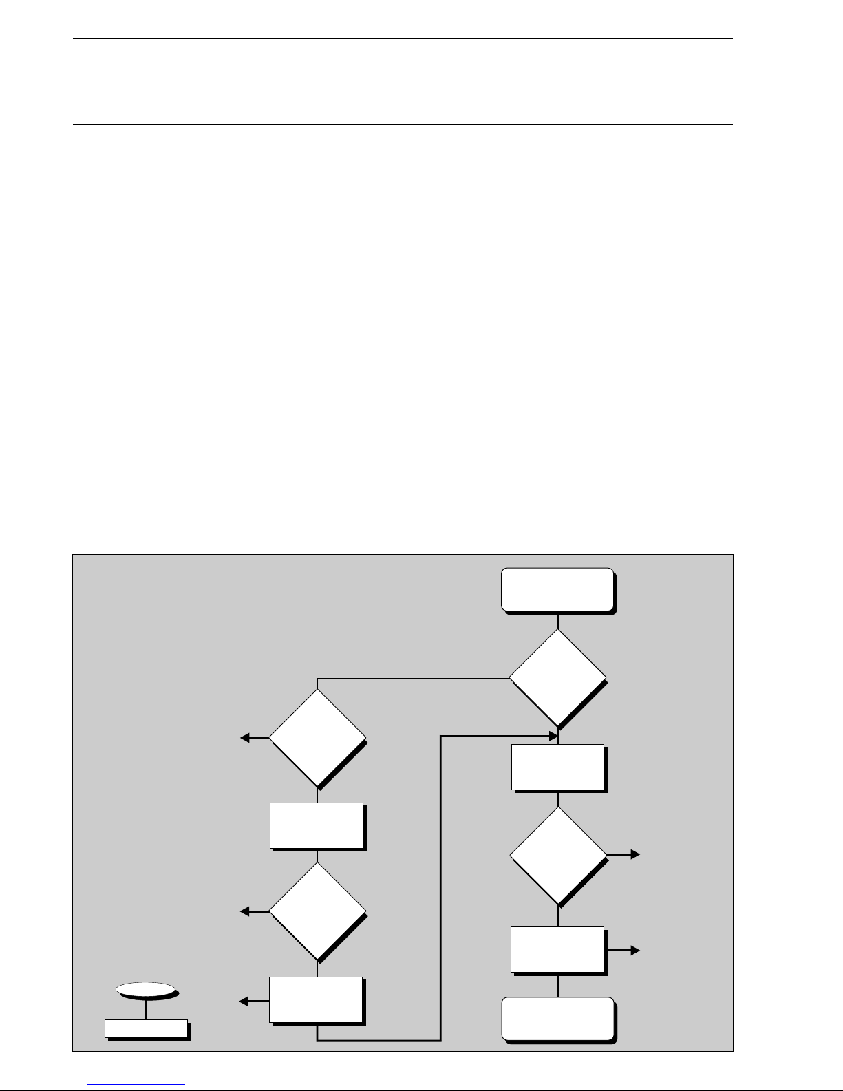
Integrated leakage test The leakage test checks whether the main gas valves are leak-tight.
(option) The supply gas pressure is used for this purpose. Since the leakage test line
(space between the two main valves) burns empty in the event of a shut-off,
this part is normally pressureless when starting (gas pressure > min. = 0).
The FMS checks this. Main gas 1 is then briefly opened and gas flows into the
test line (gas pressure > min. changes from 0 to 1). This pressure must then
subsist for 30 seconds. The leakage test is then deemed to be completed.
If the leakage test line is not empty at the start (e.g. as a result of a fault shutoff previously), main gas valve 2 is opened first. The leakage test line is thus
vented (into the combustion chamber or over the roof, depending on the
system, for suggested circuit see next page). A check is then conducted to
see whether the line remains pressureless for 30 seconds. Otherwise the
procedure is as described previously.
The leakage test can be performed before ignition and/or after shut-off.
Selection via parameters.
The pressure monitor for the leakage test line must be connected to "Gas
pressure >min” input (terminal 73). It also monitors the minimum pressure
during operation. If another minimum pressure is to be monitored during
operation, however, the pressure monitor is, for this purpose, to be looped into
the gas safety interlock circuit.
The test line, however, must be designed so as to ensure that the test time of
30 sec. per valve is sufficient to reliably detect a leak of 0.1% of the fuel gas
3
consumption at maximum firing heat output, but at least 50 dm /h.
Flow chart
Start
Leak Test
Leak
test line
under pressure
Gas > min = 1
Gas valve 1
(gas line side)
open for 2 sec.
Yes
Yes
1
1
1
1
Pressure
drops again
1
No
No
No
Pressure
rises again
No
Wait 30 sec
and
test pressure
Leak test
successfully
completed
Leak
test line
pressureless ?
Gas > min = 0
Leak
test line
pressureless ?
Parameter
770 = 1
Wait 30 sec
and
test pressure
Fault shut-off
1
Gas valve 2
(burner side)
open for 2 sec.
Yes
Yes
Page 31

Leakage Test Venting
Leakage test line over roof
Calculation formula An (approximate) formula for calculating the leak test facility is compiled
below:
Definitions: GDW gas pressure monitor
V1 gas-side safety shut-off device
V2 burner-side safety shut-off device
barometric air pressure 1000 mbar
lower switch point (falling) of GDW
upper switching point (rising) of GDW
switch difference of GDW
gas flow pressure (supply pressure before V1)
volume of gas line tested
leakage quantity
maximum admissible leakage quantity (limit)
testing time (30 seconds, fixed)
3
That is, for a maximum gas flow rate of 50 m /h the formula is:
inserting the numerical value for in mbar.
For a gas rate of flow Q of >50 m3/h the formula is:
3
inserting the numerical value for Q in m /h and for in mbar.
3
Examples: A. Assuming: = 20 mbar, gas rate of flow < 50 m /h: i.e. the gas line to be
tested must be no
3
greater than 20.8 dm
in order to be able to detect the leakage quantity demanded
3
B. Assuming: = 20 mbar, gas rate of flow = 200 m /h:
i.e. the gas line to be
tested must be no
3
greater than 83.3 dm
3
in order to be able to detect the leakage quantity demanded of 200 dm /h.
Suggested circuit for venting
the gas line over-roof in
conjunction with the
combustion management system
* If after shut-off the test line is not vented over-roof but is to be burned off
into the combustion chamber, a timer relay with a delayed cut-out of
2 … 5 sec is to be used.
PB »
PSU
PSO
DP = P SO - PSU
PG
VP
VL
VLmax
tP
D
P
D
P
D
P
D
P
31
416
30 [s]
1000 [mbar]
7
3
50 dm /h ;
VP
tP
Dp
PB
7
3
50 [dm /h] ; Y
; (3);
.
.
VP
Dp
Y VP
Dp
3
[dm ]
7
.
; (4);
Dp
3
[dm ]
VP
7
.
.
Q
0,12
.
7
7
Y VP
416
20
3
[dm ]
3
[dm ]
;
;
Y VP
20,8
7
7
Y VP
200
20
3
[dm ]
3
[dm ]
;
;
Y VP
83,3
0,12
.
to burner
Roof venting
from gas line
*K 1
P
Gas min.
Gas valve 2
Gas valve 1
82
83
Relay-Modul
6 60 R 0016
Page 32

Output regulator (optional) Method of operation
Procedure description The burner's startup proceeds exactly as already described, except that an
enabling command to start the burner must have been provided by the
output regulator. In other words, the actual value must be smaller than the
set-point by an appropriate amount.
The output regulator only operates once the burner has fired up and the
signal "Enable regulation” (terminal 4) has been given. Load specification
for the compound is then provided via the integral output regulator.
It depends on the difference between the actual value and the set-point,
and on the control parameters set.
If the actual value exceeds the maximum value set, the output regulator
shuts down the burner.
The load regulator is only active in "Automatic” mode.
Weather control If the output regulator is configured as "weather controlled”, the set-point
can be shifted between the parameters SetpointMin and SetpointMax by
altering the value at the redundant feedback channel 1.
When the regulator is weather-controlled, the outside temperature is taken
into account when calculating the set-point. The operator can input a
minimum and a maximum set-point, between which the outside
temperature can determine the set-point (see diagram).
With the weather-controlled option activated, an external set-point
specification can also be implemented.
Pre-run temperature
Outside temperature
O
120 C
O
-20 C
O
70 C
O
20 C
O
5C
O
30 C
Set-point max
Set-point min
Lower limit
Upper limit
32
Page 33

Output regulator (optional) Method of operation
Parameterised startup time
Startup circuit
Specified load
Sp
ecif
ed a
di lo
Time
max. load/
or highest
programmed
point
Specified load
Parameterised
startup load
Set-point switch-over The set-point can be switched over via a digital input. In versions with a
fixed set-point, this contact can be used to select between the two values
entered in the parameters list.
If, in addition, weather control is activated, a selection is made between
two pairs of limiting values (see Weather control and Limiting ranges). The
parameters for Set-point 1 (for set-point switch-over) and Set-point min. 1
(for weather control) are equal. Similarly for the parameters Set-point 2 and
Set-point min. 2. The relevant content is assigned in accordance with the
configuration.
Activating the "Weather control” option and adjusting the variable
parameters can also be used to implement external set-point specification.
In other words, the set-point can be altered manually or automatically via a
potentiometer (or switched through resistors). Thus, by connecting a
double-throw switch, night-time reduction could be implemented instead
of weather control. Night-time reduction and weather control can be
achieved simultaneously by combining the weather controller with the setpoint switch-over. When the weather controller is active, the compound's
feedback can no longer proceed completely redundantly.
Startup circuit The load regulator has a startup circuit, in order to brake the burner's start
load. The startup circuit is run during each new burner start. The internal
load is held at a value adjustable by the user, for as long as the boiler is
cold (actual value is below a user-adjustable limit). If the regulator's actual
value is equal to or larger than the parameterised startup maximum
temperature, this limit is overridden.
In order to prevent a situation where with an excessively large demand on
system output, the boiler temperature necessary to override the startup
circuit is not reached, a startup timer is also triggered in parallel (this timer
can also be adjusted by the operator). Once the internal load's value
reaches the parameterised startup load, the output limit is increased
linearly step-wise up to the maximum load. The slope of this linear increase
is calculated from the parameterised startup time.
33
Countdown until
the internal load
reaches the
specified load
Normal
operation
Ignition
procedure
Basic load
Ignition
Page 34

Output regulator (optional) Method of operation
Thermostat and control region The thermostat function switches the burner on or off, as a function of the
temperature and/or pressure. However, this only happens if the burner has
been enabled by the startup signal. The control region is formed by
entering the regulator's set-point and the "Burner on” value (parameter).
The shutdown hysteresis is divided into 3 regions. Generally speaking, the
first section lies below the set-point. The second section lies above the setpoint and bounds the control region, whilst the third section also lies
above the set-point and forms the rundown region.
Thus, the control region can lie asymmetrically around the set-point.
Within the upper and the lower control region, the load regulator operates in
accordance with its set parameters and specifications. If the regulator's
actual value reaches the rundown region, a basic load demand is output to
the compound. If the regulator's set-point exceeds the rundown region, the
regulator is shut down. This takes place either through internal processing
(if the controller is integral, i.e. FMS), or via a relay if the controller is an
external device (VMS). A new startup can take place once the actual value
falls below the switch-on point.
This function can replace the control thermostat required in the system.
Manual control The output regulator's load specification can be overwritten by setting the
selector switch (2) to "Load” and pressing the Channel 1 switch (4)
upwards. This manual load control is cancelled by pressing the Channel 2
switch downwards.
The shutdown limit is non-operational in manual mode. Hence the manual
mode can be used to test the safety limiter.
___________________________________________________________________
In manual mode, the load regulator's functions such as startup circuit
and control thermostat are switched off
therefore
always monitor the system continuously when using manual control.
___________________________________________________________________
Shutdown limit
Upper control
region
Set-point
Switch-on point
Shutdown
region
Control region
xxx
LAMTECLAMTEC
xxx
xxx
xxx
2
4
34
Page 35

Interpreting the display The display when "Load” is selected
The display in manual operation
Setting the output regulator The output regulator is only adjusted via the parameters.
Control region The regulator's set-point lies below the value "Upper control region”
"Burner on” value (parameter 802).
The content of the parameter "Switch-on point” is subtracted from the setpoint, giving the switch-on value. The value of the "Upper control region”
(parameter 803) is added to the set-point and forms the control region's
upper limit. Thus, the control region can lie asymmetrically around the setpoint. The switch-on point can also be above the set-point; a negative
value (<0) needs then to be input.
The rundown region is limited from above by the parameter "Burner off”
(parameter 804). The parameter is added to the set-point. If this value is
exceeded, the burner is shut down (either internally via the controller in
FMS mode, or via a relay output in VMS mode).
The region between the "Upper control region” and the "Shutdown limit” is
the rundown region. If the actual value reaches this region, the compound
returns to base load.
It also follows from the above that in general, the value in "Burner off” is
greater than the one in "Upper control region”. Otherwise there is no
rundown region, and the burner is shut down directly when reaching the
limit.
Output regulator Setting the regulator
35
Set-point Actual value Load specification Internal load
Load Internal load Actual value
specification
(via Channel 1 key)
H AH A
Shutdown limit
Upper control region
Set-point
(Parameter 796-799)
Switch-on point
Rundown region
(Parameter 804)
(Parameter 803)
(Parameter 802)
Page 36

Output regulator Setting the regulator
Regulator behaviour The load regulator attempts to adjust the actual value to the set-point.
A direct relationship between the internal load and the boiler's temperature
is assumed. In other words, the higher the internal load, the faster the
boiler's temperature rises.
The load regulator would not function if the curves were programmed
otherwise.
Four parameters determine the regulator's behaviour:
Readjustment interval
The readjustment interval determines how often the deviation is monitored
and a new adjustment calculated.
Example: a value of 10 in parameter 808 means that this procedure is
carried out every ten seconds.
The value should correspond to the control section's lag time.
P-factor
The proportional factor acts directly on the deviation, i.e. the difference
between the set-point and the actual value. The set factor is divided by 10
for the adjustment.
Example: with a set-point of 500, an actual value of 460 and a P-factor of
12, this results in a proportionality fraction of +48.
( 500 - 460 ) C12
_______________
10
I-factor
The integral factor is calculated from the momentary deviation and the
previous deviation from the set-point. The set factor is divided by 10 for the
adjustment.
Example: with a set-point of 600 and a momentary actual value of 620, this
results in an actual deviation of -20. Assume the actual value was 622 at
the last calculation, i.e. before the set readjustment interval, giving a
previous deviation of -22. With the factor set to 5, the adjustment would be
-21 points (-42 x 0.5).
D-factor
The difference factor is calculated from the change in the actual value. It is
also divided by 10.
Example: the previous actual value (before the readjustment interval) was
600. The current actual value is 605. With a D-factor of 50, this results in a
D-fraction of -25 points (-5 x 5).
36
Page 37

Output regulator Setting the regulator
Time T2 T3 T4 T5 T6 T7 T8 T9 T10
Deviation from -45 -35 -25 -15 -5 +5 +14 +22 +28
set-point
Change in +10 +10 +10 +10 +10 +10 +9 +8 +6
P-fraction +45 +35 +25 +15 +5 -5 -14 -22 -28
I-fraction +50 +40 +30 +20 +10 0 -9,5 -18 -25
D-fraction -50 -50 -50 -50 -50 -50 -45 -40 -30
Load specification +45 +25 +5 -15 -35 -40 -63,5 -80 -83
adjusted by
actual value
Max load
Load specification
Set-point
Distance
from
set-point
10 points
Actual value
Example
T1 T2 T3 T4 T5 T6 T7 T8 T9 T10
37
Parameters set in this example:
P-factor 10
I-factor 5
D-factor 50
Readjustment
interval 10 s
Page 38

Regulator behaviour All three fractions (P-fraction, I-fraction, D-fraction) are added together and
act as an adjustment to the compound regulator's load specification. The
value is added to the momentary internal load.
As long as the actual value is below the set-point, the P-fraction and the
I-fraction are positive, i.e. both these fractions act to increase the load
specification.
Only the D-fraction is still negative in such a case (assuming the boiler's
temperature is rising).
A sufficiently large D-factor should be selected, in order to avoid an
excessively large overshoot during burner startup.
The D-fraction can also be increased by increasing the readjustment
interval, since the boiler has more time for a change in temperature.
If, despite a large set-point deviation, the burner is not driven to full load or
base load respectively, the P-factor should be increased.
The larger the readjustment interval, the quieter the compound but also the
larger the actual value's deviation from the set-point and the slower the
adjustment.
The overshoot effect can result in a failure of the control mechanism, hence
the readjustment interval should be so selected that the compound
(the internal load) settles down.
Examples Parameter Name Hot water Steam
805 120 280 600
806 60 360 300
807 20 50 35
808 integral 15 2 20
implicitly optimisation is provided by customer
P-factor
I-factor
D-factor
time
Output regulator Setting the regulator
38
Page 39

Before commissioning
Adjusting motor As soon as the FMS is supplied with voltage, it attempts to drive the actuator
limit switch motors to the lower boundary of the factory curve. If the end-bearing's
limit switches are not properly adjusted for this then the motor may hit
the actuator's mechanical stop.
____________________________________________________________________
This can damage the motor or the valve.
____________________________________________________________________
Therefore:
Check the position of the end-bearing limit switches in the motors, taking
into account the motor output shaft's travel.
If in doubt, set a shorter travel. It can be readjusted later.
39
!
Page 40

40
FMS Commissioning
Function test Signal on terminal 2 = 0 Aids
Control quantity (load rating) is minimum.
Selector switch for mode (2) set to "Automatic”
Apply voltage to unit:
Unit performs a self-test
FMS appears briefly on display
Software version No. appears on display
Compare software version No. with number on the sticker
- operating display (5) lights up
- fuel LED (6 or 7) lights up
- the four "CLOSED” LEDs (B) light up A8
Selector switch (1) to "Status”
"OFF” appears on the display
Selector switch (1) to "Load rating”
The following appears:
- for external load default 200
- for internal load control unit 0
Set selector switch (1) to "Set-point feedback”
- the programmed value of the external feedback appears
(120, if no curve has yet been programmed)
Set selector switch (1) to "Actual value feedback”
- the instantaneous value of the external feedback appears
via 0 … 20 mA 0
via 4 … 20 mA 200
via potentiometer 120
(normally, but not necessarily)
_________________________________________________________
The values indicated only appear, however, if the control element is
situated at the bottom stop.
_________________________________________________________
Set selector switch (1) to "Load rating”
and
Press acceptance (3) (and keep pressed)
- The instantaneous value of the correction inputs is displayed
- KO appears between the channels
the display is in %, irrespective of the input signal setting
(0 … 20 mA or 4 … 20 mA)
»
»
»
»
»
LAMTECLAMTEC
xxx
xxx
xxx
xxx
5
B
6 7
1
ENTER
LAMTECLAMTEC
xxx
xxx
xxx
xxx
3
1
POWER OIL GAS
xxx
LOAD RATING
(CORR. INPUT)
LOAD RATING
(CORR. INPUT)
STATUS
(CORR. RANGE)
SETPOINT
FEEDBACK
ACTUAL VALUE
FEEDBACK
Page 41

41
FMS Commissioning
Set selector switch (1) to "Status” Aids
and
Press Acceptance (3) (and keep pressed)
- the instantaneously set correction range appears
- KB appears between the channels
On a 4-channel unit:
Selector switch (1) to "digital inputs”
On a 5-channel unit:
Selector switch (1) to channel 5 display
and
Press Acceptance (3)
- the condition of the digital inputs appears
- "-" signifies input not activated
- "!” signifies- input activated
Pre-ventilation suppression (terminal 1)
Significance of FMS
digital input display
! = signal present
- = signal not present
Ignition flame signal (terminal 7)
Flame signal (terminal 8)
Burner On (terminal 2)
Fault unlocking (terminal 3)
Control release (terminal 4)
Gas safety interlock circuit (terminal 5)
Re-circulation "ON” (terminal 6)
Set-point switchover (term. 70)
Air pressure monitor (terminal 72)
ext. ignition position acknowledgement (term.74)
Fuel selection (terminal 75)
Gaspressure > min (terminal. 73)
Boiler safety interlock circuit
(term. 35)
Oil safety interlock circuit (term. 69)
High firing rate acknowledgement (term. 71)
Page 42

42
FMS Commissioning Setting Control Elements
________________________________________________________
Aids
_________________________________________________________
_________________________________________________________
- “
Set "Lower stop”
Set the channel's target value to "0” via key (4)
- Red LED (B) comes on
- Actuator responds C1
- e.g. fan runs down or B1
- motor moves in the "CLOSED” direction E2
Limit switch to "CLOSED”. Adjust valve stop
Program the frequency converter to minimum rev. speed
Turn selector switch (1) to "Feedback actual value”
Adjust potentiometer to lower value
(see table below)
Set "Upper stop”
Turn selector switch (1) to "Target value”
Set target value = 999
Limit switch to "open” Adjust valve stop
Check frequency converter's maximum rev. speed
Turn selector switch to "Feedback actual value”
Check upper potentiometer value (see table)
Check rev. speed feedback value (see page 137)
Potentiometer adjustment values (approximate)
Pot Lower stop* Upper stop*
5kS 80 920
1kS 200 800
* assuming that full potentiometer rev. range is utilised
Operation of control elements
for potentiometer adjustment “Setting” mode permits direct access to the control
and limit switch settings elements. It is therefore essential to follow the safety rules
laid down by the burner manufacturer!
Adjust the control elements only when the system is at rest.
Selector switch (1) to "Actual value feedback”
Selector switch (2) to "Setting”
EI” appears on the display
LAMTECLAMTEC
xxx
xxx
xxx
xxx
2
1
CHANNEL 1 CHANNEL 2 CHANNEL 3 CHANNEL 4
LAMTECLAMTEC
xxx
xxx
xxx
xxx
A
B
ACTUAL VALUE
FEEDBACK
SETTING
Page 43

FMS Commissioning Programming Curves
_________________________________________________________
Programming the Aids
_________________________________________________________
_________________________________________________________
compound Final programming of the unit with the burner stationary can only
be done when it is certain that all feedback signals are present in
the same way as with the burner running (e.g. not
temperature-dependent or active speed feedback).
Otherwise program with burner running.
either with burner stationary
FMS
Signal on terminal 2 (burner on) = 0 Display AU
Programming can be performed only with the signal combinations
indicated. Otherwise the unit registers a fault and/or will accept no
inputs. It may be necessary to wait for the automatic firing
sequence control to release the control before programming
with the burner running (via mode "EV”, "EZ”, "EG”).
If burner drops out whilst programming in process
e.g. owing to control shut-off
- proceed to page 76 (continue programming)
If FMS skips to "ES” mode whilst programming
is in progress
- see page 76
Entirely new curve, Selector switch (1) to load rating
Clear memory - set load rating to 200 via channel 1 switch
Selector switch (1) to set-point
Mode selector switch (2) to "Clear memory”
- “SL” appears in centre of display
Press Acceptance (3):
- “cleared” appears on display
_________________________________________________________
When programming the ignition load point for the first time,
it is recommended that the FMS be initially started via the automatic
firing sequence control. At the end of the pre-ventilation time all
channels close. As soon as a switch is operated the "EI” mode is
reactivated and the ignition point can be set
_________________________________________________________
or with burner running
FMS:
Signal on terminal 2 (boiler thermostat) = 1
Wait until burner is on
_________________________________________________________
43
LAMTECLAMTEC
xxx
xxx
xxx
xxx
3
2
1
SETPOINT
ENTER
CLEAR
MEMORY
LOAD RATING
(CORR. INPUT)
Page 44

FMS Commissioning Programming Curves
st
Programming 1 point For safety reasons
(separate ignition point) "Setting” mode permits direct access to the control elements
with the burner running. It is therefore essential to follow the
safety rules laid down by the burner manufacturer!
"Setting mode” with the system running must only be
undertaken by trained and experienced personnel, whilst
keeping a constant watch on the system.
_________________________________________________________
The first point entered after clearing the memory is always the
ignition load point. This is fixed at a load rating that can no
longer be run to whilst in operation (load rating 002)
_________________________________________________________
Mode selector switch (2) to "Setting”
- "EI” appears in the middle of the display A6
Selector switch (1) to "Set point”
Switch (4) up or down
until system is optimally adjusted at ignition load point
- control element reacts E2
- display changes B1,C1,E12
On FMS 5: Selector switch (1) to "Channel 5 display”
- set point and feedback actual value are
displayed
Switch (4) (channel 2) up or down
until channel 5 is optimally adjusted
Selector switch (1) to "Actual value feedback”
- Value of the external feedback (with continuous output)
is displayed
- with three-point step channel the same value as in
"set point” position is displayed
Wait until feedback has stopped
Programming with burner running Press Acceptance (3)
(i.e. pre-ventilation has been - "Really ignite?” appears on display
carried out previously without
programmed point) _________________________________________________________
By operating the switch the ignition point
setting can be corrected again
_________________________________________________________
Aids
44
LAMTECLAMTEC
xxx
xxx
xxx
xxx
2
1
LAMTECLAMTEC
xxx
xxx
xxx
xxx
3
4
1
LOAD RATING
(CORR. INPUT)
SETTING
CHANNEL 1 CHANNEL 2 CHANNEL 3 CHANNEL 4
SETPOINT
FEEDBACK
ACTUAL VALUE
FEEDBACK
SETPOINT
CHANNEL 5
SETPOINT
ACTUAL VALUE
FEEDBACK
ENTER
Page 45

FMS Commissioning Programming Curves
Press Acceptance (3) again Aids
- burner ignites
- sep. ignition point appears on display
Programming Press Acceptance (3)
with burner stationary - ignition point 1 appears on display
nd th
Programming 2 to 19 point Selector switch (1) to "Load rating”
Run to desired load rating using channel 1 switch
Selector switch (1) to "set point”
Switch (4) up or down
until system is optimally adjusted at instantaneous load rating E2,B1,C1
On FMS 5: Selector switch (1) to "Channel 5 display” E12
- set point and actual value feedback are displayed.
Switch (4) (channel 2) up or down E12
- until channel 5 is optimally adjusted
Selector switch (1) to "Actual value feedback”
Wait until feedback has stopped
Press Acceptance (3)
- Point X appears on the display (X is the number of the A16
th
programmed point. That is, at the 4 press of the
acceptance key, point 4)
________________________________________________________
A load point on the curve must be the lowest possible load
rating that can be pre-set by the load control unit in operation,
otherwise the compound cannot completely follow the load
control unit. The compound does not go below its lowest point
even in the event of lower load requirements.
________________________________________________________
45
ÜBERNAHME
LAMTECLAMTEC
xxx
xxx
xxx
xxx
4
3
1
CHANNEL 1 CHANNEL 2 CHANNEL 3 CHANNEL 4
SETPOINT
FEEDBACK
ACTUAL VALUE
FEEDBACK
SETPOINT
CHANNEL 5
SETPOINT
ACTUAL VALUE
FEEDBACK
LOAD RATING
(CORR. INPUT)
i
Page 46

FMS Commissioning Programming Curves
Programming Selector switch (1) to "Load rating” Aids
last top point
Run to top load rating
- 999 on the display (corresponds to 20 mA on the load input) D4, D6
________________________________________________________
It is essential to run to the highest load rating that can be pre-set
by the load control unit in operation, otherwise the compound
cannot completely follow the load control unit. The compound
does not go above its highest point even in the event of higher
load requirements
________________________________________________________
Selector switch (1) to "set point”
Switch (4) up or down
until system is optimally adjusted at instantaneous load rating
On FMS 5: Selector switch (1) to "Channel 5 display”
- set point and actual value feedback are displayed.
Switch (4) (channel 2) up or down
until channel 5 is optimally adjusted
Selector switch (1) to "Actual value feedback”
Wait until feedback has stopped
Press Acceptance (3)
- Point X appears on the display
Store curve Switch mode selector switch (2) from "Setting” to "Automatic”
- "Memory” appears briefly on the display.
The curve has been transferred into the EEPROM A5, A10
Check monitoring values Mode selector switch (2) to "Monitoring display”
- The display skips to the values of the monitoring section
Selector switch (1) to "Load rating”
Run to programmed load ratings
Selector switch to "Set-point” or "Actual value feedback”
For specimen report, see appendix page 149
________________________________________________________
The monitoring values may clearly deviate from the values of the
main processor, depending on the configuration (redundant signals
or not). What is important is that the actual value and set-point
value for the respective processor agree, not that there is
agreement between the values of different processors.
________________________________________________________
46
CHANNEL 1 CHANNEL 2 CHANNEL 3 CHANNEL 4
ENTER
POWER OIL GAS ALARM
SETPOINT
FEEDBACK
SETPOINT
FEEDBACK
ACTUAL VALUE
FEEDBACK
ACTUAL VALUE
FEEDBACK
SETPOINT
CHANNEL 5
xxx
xxx
xxx
5
4
6
A
B
7 8
3
SETTING
AUTOMATIC
CLEAR
MEMORY
O -CONTROL
2
PARAMETERISATION
MONITORIN
DISPLAY
FEUERUNGS-MANAGEMENT-SYSTEM FMS
LAMTECLAMTEC
xxx
2
1
DISPLAY CHANNEL 5
(DIGITAL INPUTS)
LOAD RATING
(CORR. INPUT)
STATUS
(CORR. RANGE)
SETPOINT
i
Page 47

FMS Commissioning Programming Curves
________________________________________________________ AidsAdding points
If a curve has previously been stored that does not contain
twenty points, additional points may be added.
________________________________________________________
Mode selector switch (2) to "Setting”
Selector switch (1) to "Load rating
Run to desired load rating D2
________________________________________________________
If a flashing number appears after the load rating, instead of
adding a new point an old one is overwritten.
________________________________________________________
Selector switch (1) to "Set-point”
Switch (4) up or down
until system is optimally adjusted at the selected load rating D1,C1,E2
On FMS 5: Selector switch (1) to "Channel 5 display”
- set point and actual value feedback are displayed.
Switch (4) (channel 2) up or down
until channel 5 is optimally adjusted
Selector switch (1) to "Actual value feedback”
Wait until feedback has stopped.
Press Acceptance (3)
- Point X (number of the new load rating appears on the display,
if 6 points have previously been entered, "Point 7” appears,
only then is it classified according to its value) A16
if necessary
add further values
otherwise
Store
Note monitoring values A5,A10
________________________________________________________
Up to 20 points can be programmed. A high resolution should
also be used, since this ensures precise firing control.
It is also possible, however, to store fewer than 20 points. This is
advisable, for example when entering an initial, approximate curve.
________________________________________________________
A definitive curve for the FMS should always comprise
at least 10 points.
________________________________________________________
47
LAMTECLAMTEC
xxx
xxx
xxx
xxx
3
2
4
1
SETTING
i
Page 48

FMS Commissioning Programming Curves
Changing curve point Mode selector switch (2) to "Setting” Aids
Selector switch (1) to "Load rating”
Run to load rating with switch channel 1
the set-points of which are to be altered. Recognisable by the
flashing digits after the load rating, e.g. 687 (8) D2
________________________________________________________
A digit or "Z” must appear after the load rating, otherwise the
VMS does not accept the change and a point may be
accidentally added.
________________________________________________________
Selector switch (1) to "Set-point”
Switch (4) up or down
until system is optimally adjusted at the selected load rating D1,C1,E2
On FMS 5: Selector switch (1) to "Channel 5 display”
- set point and actual value feedback are displayed.
Switch (4) (channel 2) up or down
until channel 5 is optimally adjusted
Selector switch (1) to "Actual value feedback”
Wait until feedback has stopped
Press Acceptance (3)
- Point X (number of the new load rating) appears on the display A16
if necessary
change another curve point
otherwise
Store A5, A10
Check monitoring values
________________________________________________________
The separate ignition point can also be started up and altered
in this way.
________________________________________________________
i
48
LAMTECLAMTEC
xxx
xxx
xxx
xxx
4
3
2
1
SETTING
Page 49

FMS Commissioning O regulation
2
Automatic functions control
during operation
Checks during burner start-up This tests whether during pre-ventilation, the O actual value has complied
2
with the air value (no smaller than 18 vol.% O and smaller than 24 vol.% O ).
22
After ignition, the O actual value should have reached a value of no less than
2
14% within 45 seconds. Reaching the threshold value is monitored. If one of
the two values is not met, O regulation is deactivated. The regulator outputs
2
"Base value without regulation”.
O monitoring bands The O actual value is constantly checked during burner operation for one
22
maximum and two minimum permitted values. These ranges are located
around the O target value as a function of the load.
2
If the actual values are outside these bands over a defined period of time,
regulation is deactivated and the warning "Fault” is output. Thereafter, the
regulator output (correction input) corresponds to "Base value without
regulation” or "Base value for air shortage” as relevant.
O boundary curves
2
49
Pre-ventilation
45 sec
Time
O measured value
2
Ignition
24 %
(Parameter 905)
18 %
(Parameter 906)
14 %
(Parameter 907)
x
x
x
x
x
x
x
x
x
x
x
x
x
x
x
x
x
x
4,00
8,00
5,00
9,00
3,00
7,00
O (Vol.%)
2
2,00
6,00
1,00
100
200
300
400
500
600
700
800
900
Burner output [load]
0,00
Upper monitoring band (parameters 923 to 926)
2nd lower monitoring band
(parameters 931 to 934)
O target value curve
2
1st lower monitoring band
(parameters 927 to 930)
Adjusting the integrated This section explains only the operating steps needed to input the O curve.
2
O regulator (optional) Further information on O regulation is contained in the publication
22
DLT 5002.99cD Commissioning Supplement for the
Optional "Integrated O Regulator”.
2
Page 50

FMS Commissioning O regulation
2
Automatic functions control
during operation
The monitoring bands can be parameterised for 2 fuels, oil/gas, referenced
to each fuel (parameters 923 to 934). In the case of more than 2 curve sets,
these can be assigned to the individual curves via the parameters 912 and
913. The permitted deviation is calculated as a percentage of the target
value. Two separate percentages can be specified for basic load and full
load. The range between those is interpolated linearly.
Monitoring/shut-down times:
1st monitoring band 120 seconds; active
after "Regulator on”
2nd monitoring band 30 seconds; active
after "Burner on”
Factory settings:
1st monitoring band in the upper direction
Basic load (parameters 923/925) 60%
Full load (parameters 924/926) 100%
1st monitoring band in the lower direction
Basic load (parameters 927/929) 40%
Full load (parameters 928/930) 50%
2nd monitoring band in the lower direction
Basic load (parameters 931/933) 50%
Full load (parameters 932/934) 70%
Dynamic probe test During active operation, the measured O value is monitored by the main
2
processor for any changes. If no greater fluctuation than 0.2 vol.% O is
2
detected over a period of 10 minutes, the fuel/air mixture is altered to force
an air excess. If after 1 minute there is still no change in the actual O value,
2
the test is repeated with a higher air excess. If this does not cause a change
in the actual value, this test is repeated yet again with an even higher air
excess.
If even this does not force a change in the actual O value, the regulator
2
deactivates itself and displays a warning notice.
Thereafter the regulator output (correction input) corresponds to "Base value
without regulation”.
Probe blockage Blockages in the probe can cause the measured value to increase slowly but
steadily, in such a way that the dynamic probe test is not triggered. The main
processor monitors whether the actual O value drops by more than
2
0.2 vol.% O at least once within 15 minutes. If this is not the case, then a
2
dynamic test is triggered.
Note:
O optimisation fault messages have no effect on the burner's function or that
2
of the combustion system. They only notify that:
O optimisation was deactivated.
2
Note error status and load value.
If desired, it is also possible to have the burner shut down on "Air shortage”
faults via parameter 897.
Correction output monitoring If the O correction output is constantly greater than 98% [980 points] over
2
60 minutes, the O regulator is deactivated for safety reasons. The base
2
value for "Deactivated regulation” is output. If thereupon the O value
2
increases significantly, then the O regulator is reactivated as soon as the O
22
value is (e.g.) at another load setting in the 1st monitoring band.
50
i
Page 51

FMS Commissioning O regulation
2
Regulation strategy
The regulation strategies employed were specially developed and optimised
for the circumstances prevailing in combustion facilities:
- Frequent output changes,
- long lag times.
During burner start-up, the O regulator remains on standby until it is
2
ensured that plausible O measured values are being displayed.
2
Factory setting 90 seconds after ignition this is adjustable via parameter 904.
The "Neutral value” is output during standby.
It is calculated automatically from the range set.
Ignition takes place with the neutral value.
The neutral value depends on the selected correction mode;
e.g. at -50% to +50%, the output correction value (neutral value) is
500, whilst at -30% to +70% it is 300.
Note: The neutral value corresponds to the basic setting of the
VMS/FMS without regulation.
In the case of fuel/curve switching during operation, the neutral value is
output during the switch-over. An air advance can be set to the neutral value
by means of parameters 702 to 704.
O regulation is reactivated, with a time delay, once the switch-over is
2
completed.
Factory setting 30 seconds, adjustable via parameter 903.
Various regulation strategies are available.
In the event of a fault, "O regulation base value deactivated” or "Base value
2
for air shortage” is output, depending on the cause.
i
Burner output
(load)
Correction
Air excess
Calculated correction value
for falling load
Neutral
correction
99.9
0
min
max
Calculated correction value
for rising load
Base value for air shortage
Base value without regulation
51
Page 52

52
FMS Commissioning O regulation
2
Regulation strategy
With pre-setting for load O regulation by means of a comparison between target and actual values is
2
changes (standard regulator) only performed if no output change (load change) takes place ("internal
load” static). After a preceding load change, an target/actual value
comparison is performed and an actuation step triggered only after expiry of
the set lag time (parameters 898 and 900).
If the O actual value corresponds to its target value, the current correction
2
value, referenced to the load vale and the load direction, is stored in a table.
The updated value is output at the next load change.
A pre-update is already carried out as from the 2nd target/actual value
comparison, after a load change. As soon as the actual value gets close to
the target value, the correction value is updated.
When the load changes, regulation is terminated immediately after
target/actual value comparison and the neutral value, or if relevant the
correction value obtained (updated) for this load point,
is output D pre-setting!
Regulation after a target/actual value comparison is only performed again if
the load is stationary and on expiry of the lag time.
In this type of regulation, the overshoot is automatically deactivated in the
VMS/FMS. The actuators' hysteresis is compensated for by the load
direction-dependent updating of the correction value.
Regulation strategy with pre-setting for load changes
1 Pre-ventilation/ignition
The correction is switched off; i.e. the neutral correction value is
output.
2 O regulation on standby
2
The "Correction value with deactivated regulator” specified in
parameter 901/902 is output.
3 Regulator takes over the neutral correction value,
or the updated correction value is output.
4 On expiry of the set lag time, the residual deviation between target
and actual value is corrected.
5 Load change
O regulation is suspended and pre-setting carried out - neutral
2
correction value, or the updated correction value is output.
6 Regulation is deactivated, e.g. by a fault
The correction value for deactivated regulator specified in
parameter 901/902, or the one specified in parameter 917/918 for
"Air shortage”, is output.
Min. air overshoot
Max. fuel
Max. air overshoot
Min. fuel
t
1000
Correction value
0
Page 53

FMS Commissioning O regulation
2
Regulation strategy
Parameter 896 can be used to select whether the pre-setting is always
(at each load change) to be activated (factory setting Standard 1), or not
activated (content 2).
Furthermore, the updating too can be turned off. It is then possible to select
whether, at load changes, the neutral correction value or the "Base value
without regulator” is to be output (parameter 896).
The overshoot becomes active again when updating is turned off.
Extended regulation Regardless of the selected regulation strategy and the lag time set
strategy (air shortage) (parameter 898/900), immediate and extensive action is taken by the
regulator to combat any air shortage occurring. The objective is to avoid air
shortage and to correct any such shortage as quickly as possible.
Regulator overshooting and the resulting excess air are accepted as
unavoidable.
53
Page 54

54
!
LT1/LT2
Lambda transmitter
Analogue output 1
floating potential
657 R0051
Electric connection:
VMS/FMS Compound/
Combustion
Management System
Correction input 1
+
--
+
--
27
29
43
42
FMS Commissioning O regulation
2
Connection to the O meter
2
Via analogue interface The default for the measured O value is set via standard signal 0/4...20 mA
2
to the VMS/FMS correction input 1.
ATTENTION:
Only O meters whose t response time is < 15 sec may be connected.
2
90
Release of the analogue interface is only possible at the factory.
(Cat. no. 663 R0030).
In case of doubt, please contact LAMTEC.
Range compensation via parameters 919 and 920
Factory setting: 4...20 mA ^ 0...25.0 vol. % O
2
0 mA when O measurement is perturbed
2
Page 55

FMS Commissioning O regulation
2
Operator controls and display
Mode switching Selector switch (1) to status.
With channel key 3 in upward position, switch the display to O regulation.
2
O actual value and O target value are displayed whilst the switch is in the
22
Status position. If O regulation is deactivated, the figures are shown in
2
parentheses.
Push channel key 3 downward to return to VMS/FMS mode.
Note: O actual and target values are only displayed if O regulation or
22
O display are activated by means of parameter 896.
2
In automatic operation, the display switches during regular operation to the
O regulation mode. During burner start-up and with the basic load,
2
VMS/FMS text mode is active - basic setting. However, switching the display
by means of channel key 3 is always possible. Nevertheless, the manually
preselected setting only remains in force until the next change-over into
"Regular operation” or "Basic load regulation”, and then returns
automatically to the basic setting.
In "O regulation” mode, and with the selector switch in the Status position,
2
pressing the Acceptance key calls up commentary texts (running texts)
relating to O regulation.
2
The selector switch position (2) O Regulation serves only for the input of
2
O target value curves.
2
55
O2 (I03.4 S03.1)O2 (I03.4 S03.1)
POWER OIL GAS
ALARM
Channel-1 Channel-2 Channel-3 Channel-4
O regulation
2
deactivated
i
POWER OIL GAS
ALARM
Channel-1 Channel-2 Channel-3 Channel-4
O2 I03.4 S03.1O2 I03.4 S03.1
O regulation
2
activated
ENTER
LAMTECLAMTEC
Feuerungs-Management-System FMS
PARAMETERISATION
O -CONTROL
2
SETTING
AUTOMATIC
CLEAR
MEMORY
MONITORING
DISPLAY
LOAD RATING
(CORR. INPUT)
SETPOINT
(running time-meter)
STATUS
(CORR. RANGE)
ACTUAL VALUE
FEEDBACK
SETPOINT
FEEDBACK
DIGITAL
INPUT
1
2
ENTER
LAMTECLAMTEC
Feuerungs-Management-System FMS
PARAMETERISATION
O -CONTROL
2
SETTING
AUTOMATIC
CLEAR
MEMORY
MONITORING
DISPLAY
LOAD RATING
(CORR. INPUT)
SETPOINT
(running time-meter)
STATUS
(CORR. RANGE)
ACTUAL VALUE
FEEDBACK
SETPOINT
FEEDBACK
DIGITAL
INPUT
Page 56

56
FMS Commissioning O regulation
2
Operator controls and display
Calling up O regulation - Switch display to O regulation.
22
text messages
Selector switch (1) to "Status”.
Channel key 3 (4) upwards.
- Call up text messages by pressing the Acceptance key (3).
- Back Z press the Acceptance key (3) again,
or turn selector switch (1) to a different position.
xxx
LAMTECLAMTEC
xxx
xxx
xxx
4
3
1
O2 - regulation active
Page 57

57
FMS Commissioning O regulation
2
Commissioning
F the electronic compound completely.
The integrated O regulator remains deactivated.
2
Set parameter 896 to 0 "No regulator”
or 3 " Only display ”.
Setting the correction The integrated O regulator is connected inline and upstream of the
2
range and correction mode FMS, as a free-standing program block. It acts exclusively on
correction input 1. The correction signal (actuation signal) transmitted to
the FMS is 0...100% with a resolution of 0.1%.
0% corresponds to maximum excess air, 100% to minimum excess air.
The factory setting is a correction mode of +60 / -40 when correcting for
air-valve / fan and -60 / +40 when correcting for fuel and a neutral value
(base setting with the O regulator switched off) of 50%.
2
This basic setting was selected on the assumption that over time, burner
and boiler contamination during their operation would result in the
installation's flow resistance increasing and thus a somewhat greater
actuation range in the excess air direction could be of benefit.
If some other correction mode is selected by means of parameter 437
(expert level), the base setting also alters at the same time.
With correction mode Base setting
+50% ___- 50% 50.0%
-50 %___+ 50% 50.0%
+70%___- 30% 70.0%
-70 %___+ 30% 30.0%
0% ___-100% 0.0%
-100 % ___ 0% 100.0%
The base setting can be called up when the O regulator is switched off,
2
e.g. when the burner is off, during burner start-up etc, by turning the selector
switch to Load (correction input) whilst simultaneously pressing the
Acceptance key.
Details and examples see "Correction input", page 63 - 64.
irst adjust
Page 58

FMS Commissioning O regulation
2
Commissioning
Inputting the Calculation of O target values as part of burner adjustment
2
O setpoint curve
2
Note: O -regulated operation is the normal operation. Unregulated
2
operation should only be considered to be the emergency situation.
Hence, the objective of burner adjustment should be to calculate the
optimised operation and to store the corresponding curves in the
VMS/FMS. The O values calculated as part of burner adjustment are
2
now input as target values for O regulation.
2
The excess air required for unregulated operation is set via the base
value without regulation (parameters 901/902). This is specified during
Regulation off, Regulation in standby etc.
The O values calculated during burner adjustment are input and stored as
2
follows, regardless of whether the burner is off or in operation. The O target
2
values can be input arbitrarily. It is not necessary to observe any particular
sequence.
Set selector switch (2) to O regulation.
2
Delete the whole O curve with
2
channel key 4 (4) upwards.
If only points need to be changed, push
channel key 4 (4) downwards.
Set selector switch (1) to Load.
Using channel key 1 (5), the composite curve's programmed load points
can now be called up.
Note: The O target values can only be stored in the programmed load
2
points. If load points are skipped, the line in between is interpolated.
- Set selector switch (1) to target value.
- Channel key 4 (4) is used to set the required O target value.
2
- Press the Acceptance key (3).
Note: Each stored O target value can be changed as many times as
2
necessary, including immediately after storing it.
Set selector switch (3) to Load and
use channel key 1 (5) to call up the next load point;
etc.
As soon as all required O target values have been entered,
2
set selector switch (2) back to Automatic.
The O target value curve is now stored.
2
i
58
X
X
X
X
X
X
X
X
X
5
Vol.% O
2
Typical O target value curve
2
Load
4
3
2
1
0
200
400
600
800
1000
0
i
i
xxx
xxx
xxx
1
3
5
4
LAMTECLAMTEC
xxx
2
O2 I 2.3 S 2.7
Page 59

Calculation and setting
of control parameters
- Manual Run burner on low load.
Set selector switch (2) to O regulation
2
Text message appears
Push channel key 4 (5) downwards
Text message disappears
Set selector switch (1) to target value
Push channel key 2 (4) upwards
The O regulator is activated when this is set.
2
The O target value can now be adjusted using channel key 3 (6) within a
2
range of +3 to -1 vol.% O from the target value entered. The change in the
2
actual O value can be observed at the same time on the display.
2
Channel key 3 (6) upwards Z more O
2
Channel key 3 (6) downwards Z less O
2
The setting of parameters 898/899 and 900 should be such that the next
target/actual value comparison (actuation pulse) takes place only if the O
2
actual value has changed discernibly. A symbol +;-at the centre of the target
value display indicates that a target/actual value comparison is being
performed.
No change or change too small:
Increase P-factor parameter 899.
For details see page 60.
Note: The P-factor (proportionality factor, parameter 899) is specified by
means of the parameter setting. The new correction is obtained
from the two input quantities, deviation and P-factor. The former is
then output to the FMS/VMS.
The procedure is repeated after the lag time's expiry. If the internal
load has changed during this time, the O regulator exits this
2
routine. It must then be reactivated again as described above, via
channel key 2 (4).
Deactivating test mode
Push channel key 2 (4) downwards
FMS Commissioning O regulation
2
Commissioning
Calling up the Turn selector switch (1) to Status
correction range set
Press the Acceptance key (3)
The selected correction range appears on the display.
If both correction inputs act on one channel, the sums are shown.
Press the Acceptance key (3) again, or
turn selector switch back (1) Z return to normal display.
___________________________________________________________________
The correction should be taken into account during later programming.
The correction should be able to act without the FMS reaching the end
of its travel (0 or 999 or end-switch values).
If the correction cannot drive the servo because a channel has reached the
range limit obtained during pre-ventilation, burner output is increased or
decreased until the correction can be effected. This function can be
switched off via the parameter 0 - Release level 2. Content 0 Z off!
___________________________________________________________________
_
xxx
xxx
xxx
3
C
2
LAMTECLAMTEC
xxx
1
59
K1 - 30 70
i
xxx
xxx
xxx
4
6
5
1
LAMTECLAMTEC
xxx
2
O2 I 2.3 T 2.7
T-On
T-Off
Page 60

FMS Commissioning O regulation
2
Commissioning
Lag time
Parameters 898 / 900
Regulation parameter setting
t ___ t = regulation section's lag time
14
Specified via parameters 898 and 900
The calculated value should be input by means of parameter 898.
Factory setting: 15 seconds.
The lag time can be adjusted to the load via parameter 900.
The lag time gets shorter at full load, due to the higher gas velocities.
Lag time shortening of 3 seconds is preset at the factory.
To calculate lag time at full load: proceed as described above.
Guideline for 2 or 3-draught boiler:
Parameter 898 Z 12 seconds
Parameter 900 Z 3 seconds
The P-factor should be so adjusted that a target/actual value deviation of
1...2 vol.% O is corrected within 4...6 steps without overshooting.
2
P-factor Actuation pulse too short Z increase P-factor parameter 899
Parameter 899 Overshooting Z reduce P-factor.
Repeat until the target value is corrected within ca. 4...6 steps.
Check regulator setting at intermediate and full load.
Note: It is possible to achieve optimisation by means of the P-factor
(parameter 899) and the lag time (parameters 898 and 900), that
inter alia also depends on the installation's properties; e.g. one
may set a somewhat shorter lag time if the P-factor is reduced at
the same time.
Recommendation:
Set a slightly longer regulation cycle and smaller P-factor Z safer !!!
New O target value
2
Old O target
2
value
Actuation step
0
4
t
1
1
t
1
t
2
t
3
t
4
3
3
2
2
O
2
[vol.%]
i
60
Page 61

FMS Commissioning O regulation
2
Commissioning
Setting a base value for Perturbation of O regulation causes it to deactivate, and the specified
2
"Deactivated regulator” correction value for "Deactivated O regulator” or "Air shortage” is output,
2
and "Air shortage” depending on the cause. The burner is not shut down.
Parameters 901/902 Parameter 897 can be used by the customer to specify a burner shut-down if
917/918 the perturbation is "Air shortage”.
Calling up the base value The base values for deactivated O regulation and air shortage can be called
2
for O regulation up via parameter 896.
2
deactivated / Air shortage
8 Z Correction input _ base value for "Deactivated O regulation”
2
Parameter 901/902
9 Z Correction input _ base value for air shortage
Parameter 917/918
Recommended settings:
for parameters 901/902 and 917/918
Base value for deactivated O regulation < neutral value
2
Base value for air shortage < base value for deactivated O regulation
2
Note: The neutral value is obtained from the chosen correction mode:
Correction mode +50% / -50% Z neutral value 500 ^ 50%
Correction mode +60% / -40% Z neutral value 600 ^ 60%
See also the explanations on page 66.
Factory settings
Parameters 901/902 - base value for "Deactivated O regulation” 300
2
Parameters 917/918 - base value for "Air shortage” 150
This results in the following approximate picture of burner output:
Automatic: In preparation
i
O
2
[vol.%]
Regulated operation
Base value for air shortage
Base value for
"Deactivated O regulation”
2
4
3
2
1
0
Burner output
(load)
61
Page 62

62
FMS Commissioning O regulation
2
Operation
The meaning of the op O regulation on standby (during burner start-up), or O regulation
22
additional modes temporarily switched off via parameters 914 and 915 as a function of
load.
or O regulation active.
2
ot O regulation temporarily deactivated (air shortage, probe dynamics
2
etc).
od O regulation deactivated (perturbed), e.g. test routines failed during
2
burner start-up, dynamic test negative, O regulation temporarily
2
deactivated for over 1 hour etc.
Resetting od: Manually
Switch to "O regulation” mode.
2
Press the Acceptance key and call up error text.
Push key 3 (2) upwards Z error deleted.
ATTENTION: If deleting an error, the error text must always first be called
up by pressing the Acceptance key.
Automatic
During each new burner start-up.
Calling up O regulation
2
text messages
- Switch display to O regulation mode.
2
Selector switch (1) to "Status” and channel key 3 (2) upwards.
- Call up text messages by pressing the Acceptance key (3).
- Back Z press the Acceptance key (3) again,
or turn selector switch (1) to a different position.
xxx
LAMTECLAMTEC
xxx
xxx
xxx
- - - - or - - - -- - - - or - - - -
xxx
LAMTECLAMTEC
xxx
xxx
xxx
2
3
1
2
!
O regulation active
2
Page 63

FMS Commissioning Correction
________________________________________________________
Set correction input If corrective intervention is desired: Aids
Make sure that correction input is set
Correction signal: terminals 27 and 29 (correction input 1) or
Correction signal: terminals 33 and 34 (correction input 2)
The correction is set via the parameter numbers 429-676, of
which, however, only a fraction are generally released for use
by the person commissioning.
The following settings are possible,
expert level only (level 2):
Current signal:
Correction input 1 0 … 20 or 4 … 20 mA Parameter 431
Correction input 2 0 … 20 or 4 … 20 mA Parameter 432
Correction mode:
Correction mode for correction input 1 Parameter 437
Correction mode for correction input 2 Parameter 441
________________________________________________________
Correction mode and input signal are quoted in the order and are
set at the factory. Any change on site is possible only by
parameter intervention at expert level.
63
Available correction modes The correction mode specifies how the correction should act.
Manifold settings are possible. Diagrams 1 and 2 show two
typical correction modes for O correction.
2
Type 1: correction acting Type 1 is used if the correction is applied to a linear actuator,
on the target value e.g. a frequency converter shifting the combustion air blower's
rotation speed. The correction is directly added to, or subtracted
from, the target value.
Correction mode: acting on the target value axis
= programmed curve
= correction range
If the correction is applied to a fuel actuator, the effect is
reversed so that 0% corresponds to the smallest target value.
By using the expansion factor held in parameter 433 - Commissioning level - the correction effect can also be weighted across
the burner's output.
0 %
60 %
100 %
Load
Air actuator
Correction range
+ 60 % ...- 40 %
Neutral
value
Page 64

FMS Commissioning Correction
Factory setting:
Expansion factor 10; ^ 1.0, i.e. no weighting
Expansion factor > 10; the correction increases
with rising burner output;
Expansion factor < 10; the correction decreases
with rising burner output.
For details see VMS Commissioning instructions, under Auxiliaries, p. 30.
ATTENTION:
When applying O corrections, make sure that the combustion limits
2
are observed even with the maximum correction applied (100%). For
details see page 67, "Checking the combustion engineering limits”.
Load
Fuel actuator
> 10
Correction range
+ 30 % ... -70 %
!
100 %
Expansion
70 % factor
0 %
Type 2: correction acting Correction mode: applied to the load axis
on the load axis This is used if correction is made via a non-linear actuator, e.g. air flap. The
curve's slope is taken into account before calculating the correction. Thus, a
flat curve results in a small correction range, whilst a steep curve results in a
large one.
ATTENTION:
This is only meaningful if the curve rises monotonically.
ATTENTION:
When applying O corrections, make sure that the combustion limits are
2
observed even with the maximum correction applied (100%). For details
see page 67, "Checking the combustion engineering limits”.
Load
Correction
effect
Air actuator
Correction range
+ 60 % ...- 40 %
!
!
64
100 % 60 % 0 %
Page 65

FMS Commissioning Correction
_________________________________________________________
The correction mode indicates how the correction is intended to Aids
act. A variety of settings are possible. Figure 1 and 2 show two
typical correction modes for O correction.
2
Type 1 is used where the correction is made on a linear control
element, such as a fan frequency converter. The correction is
directly added to or subtracted from the set-point value.
Type 2 is used where the correction is made on a non-linear
control element such as an air damper. Before determining the
correction, account is taken of the steepness of the curve. A flat
curve results in a small correction range, whereas a steep curve
give a large range.
If the correction is made to a fuel control element, the effect of the
current is reversed, so that 0 mA corresponds to the smallest
set-point.
_________________________________________________________
Do not use if parts of the curve are horizontal.
_________________________________________________________
Setting the correction range: The correction range can be set between 0 and 999 via
parameter 517, commissioning level.
Example: A typical correction range for O regulation
2
is 200. This means:
With a correction mode of +40% ... -60%
(factory setting) and correction for a target
value of +80, the actuation range across
which the correction can be applied is
-120 points.
Recommendation: The correction mode and correction range
should be so chosen that the effect on the
O value in the direction
2
of excess air is -2 to 3 vol.% O ,
2
and the effect in the direction
of air shortage is 1 to 1.5 vol.% O
2
Recall set correction range Selector switch (2) to "Setting”
Selector switch (1) to "Status”
Press Acceptance key (3)
Set correction range appears on the display on the respective
channel.
If two correction inputs act on one channel, the ranges are
displayed alternately (e.g. 15 points)
If "OFF” appears
on the display, no correction is activated for this channel
_________________________________________________________
Take account of correction in subsequent programming
The correction must be able to act without the FMS reaching the
stop (0 or 999 or limit switch values).
If the correction cannot extend the adjustment travel because a
channel does not reach the range limit determined for
pre-ventilation, the burner output is increased or reduced until
the correction can be extended.
_________________________________________________________
LAMTECLAMTEC
xxx
xxx
xxx
xxx
3
C
2
1
i
!
65
Page 66

FMS Commissioning Correction
___________________________________________________________________
Altering the correction range
The parameters must be changed to allow the correction range to be
altered. These parameters are accessible via Customer level (Level 1).
___________________________________________________________________
Proceed as described under Parameter setting.
The values associated with the correction range are stored in
parameters 517 and 597.
Examples and illustrations Correction mode +70% ... -30% (recommended for air correction)
+70% corresponds to correction input value 0
- 30% corresponds to correction input value 1000
Base value 700 ^ 70%
Correction mode -70% ... +30% (recommended for fuel correction)
- 30% corresponds to correction input value 0
+70% corresponds to correction input value 1000
Base value 300 ^ 30%
Correction modes: Correction for air actuator Correction for fuel actuator
(valve/revs)
Base setting Base setting
+50 % ___ - 50 % 50 % - 50 % ___ +50 % 50 %
+60 % ___ - 40 % 60 % - 60 % ___ +40 % 60 %
+70 % ___ - 30 % 70 % - 70 % ___ +30 % 70 %
+80 % ___ - 20 % 80 % - 80 % ___ +20 % 80 %
+90 % ___ - 10 % 90 % - 90 % ___ +10 % 90 %
+100 % ___ - 0 % 100 % -100 % ___ 0 % 100 %
Base value 700
Correction input value
0 = 0%
Correction input value 1000 ^ 100%
Actuator position
1000
+ 70
- 30
1000 Load
0
0
Base value 700
Correction input value
100 ^ 100%
Correction input value 0 ^ 0%
Actuator position
1000 Load
1000
+ 30
- 70
0
0
66
Page 67

FMS Commissioning Run to shut-off limits
Run to shut-off limits As each monitoring system the FMS has tolerances, which affect the
adjustment precision. With the FMS these tolerances can be affected by
parameter settings.
If the firing system is adjusted, it has to be ensured that also the flame burns
reliably and stably in consideration of these tolerances. In order to prove this it
is necessary not only to prove the compound settings to the adjusted
setpoint, but to the so-called shut-off limits, i.e. with the actuator values, that
the FMS can take due to the permissible tolerances without shutting off just
yet.
This inspection has to be performed for the whole load range and for every
operating mode. This inspection can be abandoned if:
! the system is equiped with a failure-safe O - or CO-control, which causes
2
the shut-off of the burner due to an uncomplete combustion.
or
! the system is equipped wiht a failure-safe O / CO- regulation, which
2
compensates the tolerances of the combustion.
or
! it is guaranteed that the relevant operating mode gets as much excess air
over the full range, that the tolerances of the FMS do not have any effect.
or
! the parameters of the FMS are set that way, that the tolerances to air
deficiency are 0 digits, i.e. there are existing only tolerances to excess air.
___________________________________________________________________
If You abandon the inspection of the shut-off limits due to one of these
measures, You have to check the effectiveness of this measures, i.e. the
O / CO- regulation respectively O / CO- control the stability of the
2 2
combustion at the adjusted shut-off limits value are to be checked.
___________________________________________________________________
Due to the evidence of conformity to public and inspection authoroties and
quality management , liability reasons etc. we would therefore strongly
recommend that You always document the run to shut-off limits. You will find
an example protocol in the appendix page 158.
___________________________________________________________________
___________________________________________________________________
Repeate this methode for all relevant operating modes (curve sets). As the
case may be the above described inspection has to be executed in direction
excess air instead of direction air deficiency if You cannot ensure that with
the adjusted limits direction excess air, the flame burns reliably and stably and
no CO arises from excess air.
___________________________________________________________________
Checking the shut-off limits Selector switch (1) to "Load rating”
at three-point step output
Run to load point to be checked
Wait until the system has run to that point
Mode selector switch (2) to "Setting”
Adjust set-point value (4) of the three-point step channel in
the air deficiency direction (for dead band setting, see parameters 62-76)
Check combustion
Reset set-point value (4) to original value
In this way run all channels in succession to the limit at the
various load points -normally at low, medium and full load
67
i
!
!
!
Page 68

68
FMS Commissioning Run to shut-off limits
Checking the shut-off limits This test is necessary with the use of continuous actuators and with
at the continuous output r.p.m.regulation without the use of O /CO-regulation affecting these r.p.m.
2
of the FMS With using O regulation it can be abandonned, if the excesse air at
2
deactivated O2/regulation is higher than the setpoint
Selector switch (1) to "Load rating”
Run to load point to be checked
Wait until the system has run to that point
Mode selector switch (2) to "Setting”
Adjust set-point value (4) of the continuous channel in the air deficiency
direction until the actual value feedback has changed by the set number
the set number of points (1. monitoring band parameter 62-76)
Wait until the system has run to that point
Mode selector switch (2) to "Setting”
Check firing
Reset set-point value (4) to its origin value
Check firing
Reset set-point value (4) to the next continuous channel in air
deficiency direction.
Check firing
Repeat, until all continuous channels are checked at their limits.
___________________________________________________________________
If a correction affects the continuous channel, the test can be omitted, if the
correction range is bigger than the adjusted monitoring band (what is ordinarily the case). Instead the firing has to be checked at maximum correctional intervention. See section 2 "Checking the O influence". The test can
2
also be omitted if the monitoriing band is set to 0 at the air deficiency side.
___________________________________________________________________
As the case may be the above described inspection has to be examined in
direction excess air than in direction air deficiency, if it cannot be ensured,
that with the adjusted excess air limits,
the combustion boundary values
The correction value can be altered as follows in order to set the correction
range and to check the combustion boundary values.
Burner on, regulator is enabled (terminal 4).
Turn selector switch (2) to O regulator
2
Explanatory text is displayed
Press channel key 4 (5) downward
Explanatory text disappears
Turn selector switch (1) to load value (correction range)
Press Acceptance key (3)
With channel key 2 (4) upwards the manual correction is switched on,
shown by the display "TK" in the middle of the display.
the flame burns reliably and stably
and that there is no "excess air CO".
___________________________________________________________________
If the system is not equipped with an extra O2- or CO-monitor, it has to be
ensured, that are kept at maximum
adjacent correctional influence.
___________________________________________________________________
xxx
LAMTECLAMTEC
xxx
xxx
xxx
4
2
1
i
!
xxx
xxx
xxx
3
4
6
5
TK-On
44.0 TK 2.344.0 TK 2.3
TK-Off
2
LAMTECLAMTEC
x xx
1
!
!
Correction
input value
O -Actual value
2
Page 69

69
FMS Commissioning Run to shut-off limits
The correction value can now be changed at will with Channel key 1 (6), with
burner on. The manually selected correction value is maintained until the
selector switch (2) is turned to some other position, or normal correction is
activated by pressing Channel key 2 (4) downward.
Adjustment of the correction range is possible via parameter 517 (with the burner
operational). In the event of several fuels (curve-sets), the range can also be
adjusted individually for each curve-set and channel via parameters 517 to 596
(expert level).
To ensure that with deactivated O2-control the tolerance to the air deficiency
side is not growing, the Parameters 917, 918 and 901, 902 have to be set to
the corresponding value. This value depends on the selected correctional mode.
Empirical formular (+correctional mode x 10.)-100
Example 1:
correctional mode +60/-40
Z the parameters have to be smaller than 500, i. e. every value
between 0 and 500 creates an exceed air
( 600 would correspond to the setpoint curve)
Example 2:
correctional mode +70/-30
Z the parameters have to be smaller than 600.
Tolerance limits direction The parameter values direction air deficiency have to be known to run the test.
air deficiency The factory settings of the relevant parameters are noticed on the
configuration button.
___________________________________________________________________
If during the commissioning the factory settings of the dead band and the
monitoring bands were changed, this has to be documented externally.
The entries on the configuration button have to be set to status quo in nonblurable permanet manner. ( par example with water proofed permanent marker)
___________________________________________________________________
Tolerances in direction air deficiency do not exist if the following parameter
settings are kept :
Z For fuel channels and recirculation channels dead band in positive direction
parameters 42 - 46 = 0 digit
Z For air channels dead band in negative direction
parameters 32 - 36 = 0digits
Furthermore the "Band shift in the event of a change in power"
(par. 709 - 712) must have the same value as the monitoring band of the
respective channel in direction air deficiency (pa,r. 62 - 76) for there will be no
tolerances in direction air deficiency in the case of changing power.
From delivery date 01.02.04
We recommend the documentation in the form of a protocol. This protocoll may
be included in the setting protocols of the burner.
___________________________________________________________________
Indication for an example With help of the protocol it can be proven, that an inspection of the shut-off
protocol (next page) limits is not necessary due to the parameter settings. The values of the
settings are entered to the table. The gray highlighted numbers identify the
parameter numbers or numbers where the respective settings normally are
stored. The statements 1-6 have to be confirmed by signature. Delete as
applicable. A statemen has to be enlisted, why excess air doesn't have to
be considered. Otherwise the inspection for excess air has to be
confirmed.
it corresponds to the factory settings.
Changing this settings requires the documented inspection of the combustion
limits like described before.
___________________________________________________________________
As the case may be the correctness of these parameter settings must be
proven outwards. This can be done with reading the parameters directly on
the device or with the remote software and another adequat tool for analysis
respectively.
!
i
i
Page 70

IFMS Commissioning Run to shut/off limits
Example protocol for the evidence of the parameter settings of the monitoring bands
Protocol Monitoring band, Dead band and correctional settings FMS
date serial no. system
operational mode:
tolerances to air deficiency side
Channel Functions Dead Band Monitoring Band Band Shift
Channel 1 356 32 / 42 62 / 72 708
Channel 2 357 33 / 43 63 / 73 709
Channel 3 358 34 / 44 64 / 74 710
Channel 4 359 35 / 45 65 / 75 711
Channell 5 360 36 / 46 66 / 76 712
Correction
adjustment adjustment correction correction value correction value
direction direction range at deactivated at air deficiency
air deficiency excess air O -control
2
factory settings 40 : 60
(delete as applicable)
1. The dead band in direction air deficiency is always 0 digits
2. The band shift has at least the same size as the monitoring band in direction air deficiency.
3. With r.p.m control of the air for combustion fan the monitoring band in direction air deficiency is 0 digits.
st nd rd
4. If 1 und 2 and as the case may be 3 are fullfilled the following applies:
A tolerance to air deficiency side does not exist, therefore no inspection of the shut-off limits in direction air
deficiency has to be performed.
1)
5. An Inspection at excess air is not performed because: ...............................................................
6. It is ensured that with deactivated O -regulation the burner is run with more excess air than with operation at the
2
setpoint curves. (which correspond to protocol of the burner settings)
I have veryfied the circumstances above.
name company signature
1)
If this sentence is cancelled, a test protocol for the shut-off limits at excess air has to be provided.
517
901
902
917
918
70
Page 71

FMS Commissioning Tips & Tricks
st
Programming 1 point If no separate fuel/air ratio is to be set for the ignition point Aids
(ignition load point) (selectable via parameter 4= 0 or 2), proceed as described here.
________________________________________________________
For safety reasons
"Setting” mode permits direct access to the control elements
with the burner running. It is therefore essential to follow the
safety rules laid down by the burner manufacturer.
"Setting mode” with the system running must only be
undertaken by trained and experienced personnel, whilst
keeping a constant watch on the system.
________________________________________________________
The first point entered after clearing the memory is always the
ignition load point. This need not be the lowest load point, it is
possible to enter ones lower than this.
At least 1 point must be entered in order to form a new curve.
A subsequent addition up to 20 points is possible at any time,
see "Adding points” on page 47.
________________________________________________________
Mode selector switch (2) to "Setting”
- "EI” appears in the middle of the display A6
Selector switch (1) to "Load rating”
Run to ignition load point by means of channel 1 switch (4) D1, D2,
D5
Selector switch (1) to "Set point”
Switch (4) up or down
until system is optimally adjusted at ignition load point
- control element reacts
- display changes E2
Selector switch (1) to "Actual value feedback”
! - Value of the external feedback (with continuous output)
! is displayed
! - with three-point step channel the same value as in
! "set point” position is displayed B1, C1
!
On FMS 5: Selector switch (1) to "Channel 5 display”
- set point and actual value feedback are displayed.
Switch (4) (channel 2) up or down
until channel 5 is optimally adjusted
Wait until feedback has stopped
Programming with burner running Press Acceptance (3)
(i.e. pre-ventilation has been carried - "Really ignite?” appears on display
out previously without ________________________________________________________
programmed point): By operating the switch the ignition point setting can be
corrected again.
________________________________________________________
71
LAMTECLAMTEC
xxx
xxx
xxx
xxx
2
1
LAMTECLAMTEC
xxx
xxx
xxx
xxx
3
1
CHANNEL 1 CHANNEL 2 CHANNEL 3 CHANNEL 4
4
ENTER
ACTUAL VALUE
FEEDBACK
SETPOINT
LOAD RATING
(CORR. INPUT)
SETTING
Page 72

FMS Commissioning Tips & Tricks
Press Acceptance (3) again
- ignition position relays pull up
burner ignites
- ignition point 1 appears on display
Programming
with burner stationary Press Acceptance (3)
- ignition point 1 appears on display
72
Reversing the programming If you have started programming and do not want to save these values, but
to re-activate the old curve instead.
Selector switch (2) to "Clear memory”
Selector switch (1) to "Set-point”
Press Acceptance (3)
- “cleared” appears on the display
Selector switch (2) to Automatic
- The old curve is valid again.
___________________________________________________________________
The unit recognises that the RAM does not contain a valid curve that could
be transferred to the EEPROM. The last valid EEPROM curve is therefore
re-activated.
___________________________________________________________________
Instrumentation When commissioning systems with the FMS it is recommended that several
for commissioning 5K potentiometers with ready-made connections and at least 2 current
transmitters be always carried, (particularly where the continuous outputs
are used).
The current transmitter should be adjustable in the range 0 … 20 mA.
A voltage range of 0 … 10 V would also be advantageous in order to be able
to simulate the continuous voltage output of the FMS.
In addition 2 multimeters (measuring ranges: current, voltage, resistance)
should be to hand when commissioning.
xxx
xxx
3
2
1
xxx
LAMTECLAMTEC
xxx
Page 73

FMS Commissioning Tips & Tricks
Adjusting load ratings individually - when load points are to be adjusted without programming
a complete curve
___________________________________________________________________
When adjusting individual points it is normally only possible to freely adjust the
set-point values. This is done by running to the load value (figure appears after
the value). The associated set-point can be adjusted. The figure, which shows
that the change is admissible, appears not only right at the programmed load
point but also in the range ± 3 points around this. When stored, however, the
value actually displayed is adopted.
At each adjustment of individual points it is therefore possible to shift the load
value by up to 6 points.
___________________________________________________________________
Procedure for shifting the load value:
Undertake operations as described under "Adjusting individual points”
but shift the load rating as required,
Set set-point value
Store
If the desired load rating cannot be achieved in one operation:
Repeat procedure
- Output point is now the last curve entered
Entering an initial curve Since, prior to initial programming, the set-point EEPROM contains a
standard curve that very probably doe not correspond to the actual
conditions of the system (ranges, set-point values), the following
procedure is recommended for the initial curve:
Make sure that the signal wiring is correct
- see Function test and Manual
Clear memory
Leave FMS at "Setting”
Have system started up without control release (terminal 4)
After pre-ventilation, enter ignition load point
Ignition
Give control release (terminal 4)
Enter further points with burner running
Store
73
Page 74

FMS Commissioning Tips & Tricks
_______________________________________________________________
Approaching control During operation the compound approaches the control elements from one
elements from one side side in order to compensate for the mechanical hysteresis of the valves,
approaching all set-points from above.
Exception: The top point is never overrun and therefore approached
from below.
When setting, care should be taken to approach the valves in the same way.
As a result the system values in automatic mode are reproduced in exactly
the same way.
___________________________________________________________________
Entering settings Selector switch (2) to "Setting”
Run to desired set-point from above
if accidentally running below this point
Run above set-point and re-approach from above
Entering top setting Selector switch (2) to "Setting”
Run to desired set-point from below
if accidentally running above this point
Run below set-point and re-approach from below
___________________________________________________________________
Only in this way will you reach the same valve position and hence also the
same combustion values in setting as later during automatic operation.
___________________________________________________________________
Ignition delay when setting When the ignition point is entered for the first time the facility exists for
observing the ignition process by entering a delay time. To do this, the time
needed to run to the burner sight glass and to the boiler end respectively must
be set in parameter 759.
As soon as the question "Really ignite?” is confirmed by pressing the
acceptance key, this time expires. On expiry the ignition is released.
This time operates only if the FMS is on "Setting”.
Pre-setting load automatically Parameter 4 can be used not only to select the separate ignition point but
also to determine whether the load default is to be automatically pre-set
during setting. If this is the case the load points (in addition to the ignition
point) are fixed at the values 200 (corresponding to 4 mA at the load input),
250, 300, 400, 500, 600, 700, 800, 900 and 999.
It is then possible to switch only between these points by means of the load
rating switch position. You cannot run to intermediate values during setting.
Storing a point causes the load default to skip to the next value (unless this is
already taken up). In this way a curve can be entered without shifting to load
rating.
74
Page 75

FMS Commissioning Tips & Tricks
Entering the compound curves ___________________________________________________________________
with the burner stationary In order to be able to program the FMS without a flame, the fan must be in
operation (at least where a speed-controlled fan is actuated by the FMS)
___________________________________________________________________
Apply 230-V signal to fan
- e.g. Bridge terminal 81 and terminal 89 on relay R 18
(caution: as a result, terminal 92 also receives a voltage)
Disconnect "Burner On” signal (terminal 2)
so that burner does not start
Enter curve
Connect fan actuation again (e.g. remove bridge)
Keeping the re-circulation The pre-ventilation behaviour of the re-circulation duct according to the
damper closed in pre-ventilation technical regulations on steal boilers [TRD] is incorporated into the software of
the FMS. That is, the re-circulation dampers always open with a delay.
If the system subsequently requires the re-circulation to remain closed during
pre-ventilation, this can be achieved by means of the pre-ventilation limit
parameters (parameter 346-350).
Clear range limits
Selector switch (2) to "Clear memory”
Press Acceptance
- Selector switch to Automatic
Select pre-ventilation limit parameter for the re-circulation duct
Enter CLOSE position of the re-circulation damper
Have range limits re-entered through pre-ventilation
Now the re-circulation damper does not open during pre-ventilation
Setting the pilot burner ___________________________________________________________________
(servicing mode) A special function is incorporated into the FMS in order to facilitate setting of
the pilot burner. (The control unit runs only until the stabilisation time
(main valves do not open).
By doing this, up to 5 ignition attempts can be performed without prior flushing
or leakage test. Only after 5 starts does automatic flushing of the boiler occur
according to the times set on the FMS.
___________________________________________________________________
Selector switch (2) to parameterisation
Select parameter 787
Set content to "1”
- Servicing modus is active
Selector switch (2) back to Automatic
Set pilot burner
(to do this allow the burner to start quite normally)
when setting is completed
Reset parameter 787 to "0”
Switching the burner on
again via the target value
____________________________________________________________
If possible, only reset faults via short reset, otherwise the maintenance
mode counter restarts, i.e. another pre-ventilation occurs.
____________________________________________________________
If the integral output regulator is used and a negative value is entered in
parameter 802, it is possible to achieve a situation where the burner is switched
on accordingly via the target value.
i
75
Page 76

76
System Operation Mode Display
Significance of modes Abbreviation Mode
on the FMS
ON Z "Switch-on sequence”
BE Z "Ready"
ZÜ Z “Ignition position”
EZ Z "Setting/Ignition position"
GL Z "Base load”
EG Z "Setting/Base load”
NA Z "Post-ventilation"
AU Z "Off"
EI Z "Setting”
SL Z "Clear memory"
EV Z " Setting/Pre-ventilation"
ES Z "Setting/Control"
ST Z "Fault"
VO Z "Pre-ventilation"
HA or HAND Z "Manual mode"
LE Z "Load extern"
(RG) keine Anzeige Z "Control mode”
BE indicates that the signal is present on terminal 2, and all other
signals = 0
If the FMS controls a flue gas damper, this opens. It is possible to switch
to "Setting”.
ZÜ indicates that pre-ventilation is finished and the ignition position relay
EZ pulls on. The FMS is in the ignition position, but the flame signal is
absent. Switching to "Setting” merely causes the mode display to switch
to EZ. Programming is not possible in this mode.
GL indicates that the burner is on (terminal 8=1), but the control release is
EG absent (terminal 4=0). The FMS therefore remains in base load position.
Switching to "Setting” merely causes the mode display to switch to EG.
Programming is not possible in this mode
NA indicates that the FMS is in post-ventilation mode.
All signals = 0
All air ducts open. When the configured time has elapsed,
the FMS changes to "AU” mode.
AU indicates that the FMS is "OFF”. All control elements closed.
Selector switch on "Automatic”, all signals = 0.
EI indicates that the mode selector switch is on "Setting”.
Single points can now be altered or new curves can be entered.
SL indicates that the mode selector switch is set to "Clear memory”.
By pressing the acceptance key the existing curve is cleared and a new
curve can be entered.
EV indicates that although the mode selector switch is on "Setting”
it is nevertheless performing the pre-ventilation routine.
These is a signal on terminal 3.
_______________________________________________________________
If the selector switch is on "Setting” and there is a "signal on terminal 3”,
the FMS nevertheless maintains its control function.
The setting mode (display "EI”) is only activated when the pre-ventilation
is completed and there is a flame signal and control release. The FMS
can therefore only be programmed when the signal combination
corresponds either to the "AU” and/or "BE” modes, or when the signal
combination corresponds to the "Automatic” mode.
_______________________________________________________________
Page 77

77
System Operation Mode Display
ES indicates that although the mode selector switch is on "Setting”.
its control function is working according to a calculated curve in the
RAM. The curve is calculated from a partial curve already entered. This
mode is arrived at if the burner is switched off during a programming
sequence and then restarts. The programming can be continued by
operating a switch (change to "EI” mode”). Flame signal and control
release are present.
STindicates that the FMS has gone to "Fault”.
The fault code can be called up in "Status” switch position. In the "load
rating” switch position” the load rating at the time of the fault is
displayed.
VO indicates that the FMS is in "Pre-ventilation” mode. There is a signal on
terminal 2 and a signal on terminal 3. Pre-ventilation routine active.
HANDindicates that the FMS has been switched to manual mode whilst the
or burner is running. In the "Load rating” selector switch position the load
HA can now be adjusted by means of the channel 1 switch. To quit manual
mode, press a switch other than the channel 1 switch.
term.4 term.8 If also on "Setting"
0 0 0 0 AU or NA EI or EZ
1 0 0 0 BE or ZÜ EI or EZ
1 1 0 0 VO EV
1 0 0 1 GL EG
1 0 1 1 Automatic EI
ext Hand indicates that the FMS was switched to manual operation, but the load
was specified externally and not via the channel 1 key (that is, e.g. via
remote software or bus).
LEindicates that the output regulator of the FMS is deactivated and the
load is controled by an external signal.
Input terminals Mode
term.2 term.3
O regulator modes opO regulator on standby (during burner startup), or O regulator temporarily
22 2
switched off as a function of load via parameters 914 and 915.
or O regulator active
2
ot O regulator temporarily deactivated (air shortage, probe dynamics, etc)
2
odO regulator deactivated (during fault) e.g. test routines failed during
2
burner startup, dynamic test negative, O regulator temporarily
2
deactivated for longer than 1 hour, etc.
Page 78

System Operation Mode Display
"ES" Mode Should the burner skip to "ES" mode whilst programming is in progress
(set - control) ___________________________________________________________________
This mode allows the electronic compound to run within curve sections already
entered and thereby facilitates setting.
If the load drops by 40 points, the FMS skips to "ES" mode, thereby controlling
the outputs automatically.
"ES" mode is also started if the selector switch 1 is set to load rating and the
channel 2 switch is pushed up.
___________________________________________________________________
Back to normal programming:
touch a switch
- the FMS changes back to "EI" mode
Continue programming in the usual way
If the burner cuts-out whilst programming is in progress
Continue programming Should the burner cut out due to control shutoff, proceed as follows:
Undertake no further action on the FMS
Wait until the boiler temperature falls
Allow burner to start quite normally
Pre-ventilation
- "EV" appears on the display
- FMS controls the outputs according to the pre-ventilation
___________________________________________________________________
The highest load point already entered is not exceeded.
___________________________________________________________________
For your safety:
“ES" mode should be run only by trained personnel with the system
under constant supervision.
___________________________________________________________________
Run to next load rating to be programmed
Push switch up
- FMS switches back to "EI" mode
continue programming at the point where the burner cut-out previously
occurred
___________________________________________________________________
Should the mains voltage to the unit have failed (display dark, operating
LEDs out), before switching back to automatic, all curve points already entered
will have been lost. Start programming from beginning again.
___________________________________________________________________
i
!
i
i
78
Page 79

System Operation 4 Curve sets FMS
(option)
Interconnection with The FMS offers the optional facility for using 4 curve sets.
4 curve sets option In this case 2 curve sets are firmly assigned to oil operation and 2 curve sets
to gas operation. The curve sets are then selected via terminal 75 (fuel
selection) and additionally via the fuel safety interlock circuits.
___________________________________________________________________
Fuel Oil safety Gas safety Curve set
selection interlock circ. Interlock circ.
terminal 75 terminal 69 terminal 5
___________________________________________________________________
0 1 0 Curve set 1 (oil op.)
0 0 1 Curve set 2 (gas op.)
1 1 0 Curve set 3 (oil op.)
1 0 1 Curve set 4 (gas op.)
X 0 0 FMS does not start or
fault during operation
X 1 1 FMS does not start or
fault during operation
Since the fuel safety interlock circuits now serve here for selection of the curve
set, they are, contrary to the standard flowchart, monitored immediately after
starting (or more precisely after the end of t1, see flow charts) and must
remain on until burner-shut-off
79
Page 80

System Operation
Running time meter
Checksums
Recalling the checksums Selector switch (1) to "Set-point feedback”
and the safety times
Press acceptance (3) and keep pressed
- the checksums and the safety times appear one after the other
on the display
___________________________________________________________________
Each of the parameter levels is safeguarded by its own checksum.
The checksums for each level and the safety and pre-ventilation times
are displayed here in succession
Order:
CRC 16 of level 0: adjustable without password
1: adjustable by person commissioning
2: adjustable by burner/boiler manufacturer
3: adjustable only by LAMTEC
4: adjustable only by LAMTEC
st
1 oil safety time in seconds
nd
2 oil safety time in seconds
st
1 gas safety time in seconds
nd
2 gas safety time in seconds
Pre-ventilation time in seconds
nd
On the FMS without pilot burner the statement of the 2 safety time contains
st
safety time. The statement of the 1 safety time is then irrelevant.
___________________________________________________________________
If the parameter was changed, the checksum changes not before a
complete reeboot of the device was made or after ca. 1h.
___________________________________________________________________
80
LAMTECLAMTEC
xxx
xxx
xxx
xxx
3
1
Calling up running Selector switch (1) to set-point
time meter
Press Acceptance (3) and keep pressed
- a moving text appears giving the following data:
- total running hours
- running hours on curve set 1
- starts on curve set 1
- running hours on curve set 2
- starts on curve set 2
____________________________________________________________
Where the 4 curve set or 8 curve set option is used the running hours and
starts on the additional curve sets are also displayed.
____________________________________________________________
The sum of the curve set 1 running hours and curve set 2 running hours does
not necessarily give the running hours value displayed in total.
The total counter relates to the FMS running hours. It runs as soon as the unit
is connected to a voltage (this also provides the basis for the fault history).
The single running time meters relate to the burner running hours.
These run as soon as the burner is in operation with the respective curve set
(flame signal to the FMS)
___________________________________________________________________
SETPOINT
ENTER
i
i
Page 81

System Operation Messages / Faults
____________________________________________________________
What happens in the event If the processor detects a fault, it runs the outputs in the programmed direction,
of FMS fault e.g. air on, fuel off, re-circulation closed
The fuel solenoid valves close. The fault signal relay pulls on with a few
seconds delay. Automatic restarting may be possible, depending on the
nature of the fault.
___________________________________________________________________
Reading off a fault Red fault LED lights up
Selector switch to "Status”
- Fault code is displayed
Note code
Press Acceptance
- Plain text message appears on display incl. running time meter reading up
to the time of the fault
Selector switch on "Load rating”
- Load rating at the time of the fault is displayed (externally and internally)
Note load ratings
Resetting a fault Selector switch to "Status”
Left-hand switch up
- the fault is cleared unless the cause is still directly present.
Alternative:
FMS: Emit terminal 3 signal briefly (min. 2 seconds) via external switch.
Fault is cleared!
___________________________________________________________________
Calling up fault history The FMS stores the last 10 faults with the associated running time meter
reading.
___________________________________________________________________
Selector switch (1) to Status
- Instantaneous status appears on display
Channel 1 switch (4) up
- last fault code appears on display
- associated running time meter reading appears on display
Press Acceptance (3)
- text and running time meter reading appears on display
Channel 1 switch (4) up again
- penultimate fault code appears on display
- associated running time meter reading appears on display
In this way the fault history can be browsed through by
operating the channel 1 switch
___________________________________________________________________
If you are sure that there has been a voltage on the FMS at all times since the
last fault, the time of the fault can be determined by means of the current
running time meter reading and the current time.
___________________________________________________________________
LAMTECLAMTEC
CHANNEL 1
SETPOINT 0
1
3
xxx
xxx
xxx
xxx
4
81
i
i
Page 82

POWER OIL GAS
ALARM
Channel-1 Channel-2 Channel-3 Channel-4
ENTER
LAMTECLAMTEC
Feuerungs-Management-System FMS
PARAMETERISATION
O -CONTROL
2
SETTING
AUTOMATIC
CLEAR
MEMORY
MONITORING
DISPLAY
LOAD RATING
(CORR. INPUT)
SETPOINT
(running time-meter)
STATUS
(CORR. RANGE)
ACTUAL VALUE
FEEDBACK
SETPOINT
FEEDBACK
DIGITAL
INPUT
1
2
3
System Operation Messages / Faults
O regulation
2
O regulation perturbed In the event of perturbations, a warning message is displayed and the
2
O regulator is deactivated. The specified base value "Without regulation” or
2
the one for "Air shortage” is set.
The display shows the running text "O regulation perturbed”.
2
The burner is not shut down as a rule.
The corresponding error code can be called up by setting the selector switch
to Status. A plain text message about the cause of error appears after
pressing the Acceptance key (3).
Air shortage perturbation If the actual O value is significantly smaller than the target value and
2
corrective action by the FMS/VMS cannot rectify this error, the regulator is
deactivated and the base value for air shortage errors is output. If desired,
an air shortage burner shut-down can be triggered by the FMS/VMS. This is
achieved by setting parameter 897 to 1.
The error code is H360, "Error shut-down by O regulator”.
2
Resetting O errors O errors are automatically reset with each new burner start-up. This is
22
permissible, since a 100% O measurement test is performed at each
2
start-up.
Manual resetting of O errors is possible at any time, as follows:
2
Set selector switch (1) to Status
- FMS in O regulation mode?
2
If not, switch over to O regulation mode
2
by pushing channel key 3 (4) upwards.
Press the Acceptance key (3) and
- call up the cause of error (mandatory!)
Push key 3 (4) upwards
Calling up O regulation Switch over to FMS/VMS mode (compound regulator)
2
error history
Selector switch (1) to Status
Switch channel 3 down
- In this way the fault history can be browsed through by
operating the switch channel 2
___________________________________________________________________
The display of O history disappears automatically after 5 sec.
2
O regulator faults lasting over 30 sec are stored. They are only stored in
2
the EEPROM once the fault is cleared up or the FMS leaves the operating
mode Regulation or Base load.
____________________________________________________________
O regulation error
2
82
1
1 147 1 000 487
xxx
xxx
2 3
1 147 1 000 487
! ! ! !
Current fault Internal load Curve-set Operating hours
LAMTECLAMTEC
xxx
xxx
SETPOINT
ENTER
Page 83

System Operation Messages / Faults
________________________________________________________________
An "H” before the fault code indicates that the main processor has
identified the cause of the defect. A preceding "Ü" indicates that the
monitoring processor has triggered the fault.
________________________________________________________________
An * next to the fault code means that the control unit will attempt
restarting after a few seconds.
A flashing fault LED signals that a repeat startup is about to take place.
________________________________________________________________
D/A converter defective
Curve data are defective! Curve set No.
at parameter No.:
Inadmissible configuration in the parameters
Different digital input signals on main and
monitoring processor
CRC-16 test has discovered a fault
RAM test detects fault
Different operating mode between main and
monitoring processor
The correction is outside its admissible range,
channel 1
The correction is outside its admissible range,
channel
The correction is outside its admissible range,
channel
The correction is outside its admissible range,
channel
The correction is outside its admissible range,
channel
The EEPROM is defective
Potentiometer defect, feedback varies too rapidly: channel
Potentiometer defect, feedback varies too rapidly: channel
** means that a repeat startup is attempted arbitrarily often. The time
can be set at the factory or the restart deactivated.
Fault code number Aids
H / Ü 1 Ignition flame fails to start
H / Ü 2 Extraneous light fault
H / Ü 3 Flame fault during ignition sequence H2
H / Ü 4 ** Flame fault during operation
H / Ü 5 Flame signal does not appear during 1st safety period H2
H / Ü 6 Flame signal goes out during the stabilisation period H2
H / Ü 7 Flame signal goes out during the 1st safety period H2
H / Ü 8 Flame signal goes out during the 2nd safety period H2
H / Ü 9 Flame signal does not appear during the safety period H2
H / Ü 10 Flame signal goes out immediately after ignition H2
H 102 Internal communication FIFO memory has overflowed A7
H / Ü 103 Internal fault: EEPROM A7,A9
H 104 A7
H / Ü 105 * A7,A13,
A9
Ü 106 Unterschiedliche Parameter zwischen HP & UE, A7,A14,
A9
H / Ü 107 A7,A12
H 108 A7,G8
H / Ü 110 A7,A11
H / Ü 111 A7
H / Ü 120 * A24
Ü 121 F1
Ü 122 F1
2
Ü 123 F1
3
Ü 124 F1
4
Ü 125 F1
5
H / Ü 139 Integrierter Flammenwächter: Störung bei Selbsttest
H / Ü 140 A2,A7,
A12,A15
H / Ü 141 1 E13
H / Ü 142 2 E13
83
Fault codes
Page 84

System Operation Messages / Faults
Fault code number Aids
H / Ü 143 Potentiometer defect, feedback varies too rapidly: channel 3 E13
H / Ü 144 Potentiometer defect, feedback varies too rapidly: channel 4 E13
H / Ü 145 Potentiometer defect, feedback varies too rapidly: channel 5 E13
H / Ü 151** The deactivated re-circulation valve does not reach
"CLOSED” position rapidly enough: channel 1 E2,B1,B3
H / Ü 152** The deactivated re-circulation valve does not reach
"CLOSED” position rapidly enough: channel 2 E2,B1,B3
H / Ü 153** The deactivated re-circulation valve does not reach
"CLOSED” position rapidly enough: channel 3 E2,B1,B3
H / Ü 154** The deactivated re-circulation valve does not reach
"CLOSED” position rapidly enough: channel 4 E2,B1,B3
H / Ü 155** The deactivated re-circulation valve does not reach
"CLOSED” position rapidly enough: channel 5 E2,B1,B3
H / Ü 161** Running direction monitoring, channel 1 EE2,E17
H / Ü 162** Running direction monitoring, channel 2 EE2,E17
H / Ü 163** Running direction monitoring, channel 3 EE2,E17
H / Ü 164** Running direction monitoring, channel 4 EE2,E17
H / Ü 165** Running direction monitoring, channel 5 EE2,E17
H 171** Dead band exceeded for too long: channel 1 B1,B4,E2
E4,E5
H 172** Dead band exceeded for too long: channel 2 B1,B4,E2
E4,E5
H 173** Dead band exceeded for too long: channel 3 B1,B4,E2
E4,E5
H 174** Dead band exceeded for too long: channel 4 B1,B4,E2
E4,E5
H 175** Dead band exceeded for too long: channel 5 B1,B4,E2
E4,E5
H 181** Dead band not attained for too long: channel 1 B1,B4,E2
E4,E5
H 182** Dead band not attained for too long: channel 2 B1,B4,E2
E4,E5
H 183** Dead band not attained for too long: channel 3 B1,B4,E2
E4,E5
H 184** Dead band not attained for too long: channel 4 B1,B4,E2
E4,E5
H 185** Dead band not attained for too long: channel 5 B1,B4,E2
E4,E5
84
Page 85

System Operation Messages / Faults
Fault code number Aids
st
H / Ü 191* 1 monitoring band exceeded for too long: channel 1 B1,B3
st
H / Ü 192* 1 monitoring band exceeded for too long: channel 2 B1,B3
st
H / Ü 193* 1 monitoring band exceeded for too long: channel 3 B1,B3
st
H / Ü 194* 1 monitoring band exceeded for too long: channel 4 B1,B3
st
H / Ü 195* 1 monitoring band exceeded for too long: channel 5 B1,B3
st
H / Ü 201* 1 monitoring band not attained for too long: channel 1 B1,B3
st
H / Ü 202* 1 monitoring band not attained for too long: channel 2 B1,B3
st
H / Ü 203* 1 monitoring band not attained for too long: channel 3 B1,B3
st
H / Ü 204* 1 monitoring band not attained for too long: channel 4 B1,B3
st
H / Ü 205* 1 monitoring band not attained for too long: channel 5 B1,B3
H / Ü 211 2nd monitoring band exceeded for too long: channel 1 E11,B5
H / Ü 212 2nd monitoring band exceeded for too long: channel 2 E11,B5
H / Ü 213 2nd monitoring band exceeded for too long: channel 3 E11,B5
H / Ü 214 2nd monitoring band exceeded for too long: channel 4 E11,B5
H / Ü 215 2nd monitoring band exceeded for too long: channel 5 E11,B5
H / Ü 221 2nd monitoring band not attained for too long: channel 1 E11,B5
H / Ü 222 2nd monitoring band not attained for too long: channel 2 E11,B5
H / Ü 223 2nd monitoring band not attained for too long: channel 3 E11,B5
H / Ü 224 2nd monitoring band not attained for too long: channel 4 E11,B5
H / Ü 225 2nd monitoring band not attained for too long: channel 5 E11,B5
H 231** Compound sticking: channel 1 E2,E4,E5
C1,B1,B3
H 232** Compound sticking: channel 2 E2,E4,E5
C1,B1,B3
H 233** Compound sticking: channel 3 E2,E4,E5
C1,B1,B3
H 234** Compound sticking: channel 4 E2,E4,E5
C1,B1,B3
H 235** Compound sticking: channel 5 E2,E4,E5
C1,B1,B3
H / Ü 301* Wire break on correction input, channel 1 F2
H / Ü 302* Wire break on correction input, channel 2 F2
H / Ü 320* Wire break load input D7
85
Page 86

System Operation Messages / Faults
Fault code number Aids
H / Ü 321* Wire break feedback channel 1 E9
H / Ü 322* Wire break feedback channel 2 E9
H / Ü 323* Wire break feedback channel 3 E9
H / Ü 324* Wire break feedback channel 4 E9
H / Ü 325* Wire break feedback channel 5 E9
H / Ü 351* Barred curve change with burner running G3
put defective C4
Ü 372 Load value difference between HP and UE too great A7,D11
Ü 381 Difference between HP & UE too great
Correction input 1 A7,F6
Ü 382 Difference between HP & UE too great
Correction input 2 A7,F6
Ü 391 Fuel valves opened in ST operating mode A7,A19
H 392 Remote no longer responds (time-out)
H 393 Remote shut-off has been triggered
(shut-off via interface)
Ü 400 Different point number on acceptance A23
H / Ü 451* Ignition position was exited in ignition mode, channel 1 E18
H / Ü 452* Ignition position was exited in ignition mode, channel 2 E18
H / Ü 453* Ignition position was exited in ignition mode, channel 3 E18
H / Ü 454* Ignition position was exited in ignition mode, channel 4 E18
H / Ü 455* Ignition position was exited in ignition mode, channel 5 E18
H 500 Internal comparison: relay output terminal 67 does not pull on A19, A7
H 501 Internal comparison: relay output terminal 43 does not pull on A19, A7
H 502 Internal comparison: relay output terminal 16 does not pull on A19, A7
H 503 Internal comparison: relay output terminal 11 does not pull on A19, A7
H 504 Internal comparison: relay output terminal 45 does not pull on A19, A7
H 505 Internal comparison: relay output terminal 68 does not pull on A19, A7
H 506 Internal comparison: relay output terminal 36 does not pull on A19, A7
H 507 Internal comparison: relay output terminal 41 does not pull on A19, A7
H / Ü 352** Inadmissible curve selection (no selection signals present) G4
H / Ü 353** Inadmissible curve selection
(more than one selection signal present simultaneously) G4
H 360 Fault switch-off through integral O regulator
2
H / Ü 361 Different status from ignition position relay E6
H / Ü 370 Internal communication between processors defective A20
H 371 Internal load out
86
Page 87

System Operation Messages / Faults
Fault code number Aids
H 508 Internal comparison: relay output terminal 76 does not pull on A19, A7
H 520 Internal comparison: relay output terminal 67 does not drop out A19, A7
H 521 Internal comparison: relay output terminal 43 does not drop out A19, A7
H 522 Internal comparison: relay output terminal 16 does not drop out A19, A7
H 523 Internal comparison: relay output terminal 11 does not drop out A19, A7
H 524 Internal comparison: relay output terminal 45 does not drop out A19, A7
H 525 Internal comparison: relay output terminal 68 does not drop out A19, A7
H 526 Internal comparison: relay output terminal 36 does not drop out A19, A7
H 527 Internal comparison: relay output terminal 41 does not drop out A19, A7
H 528 Internal comparison: relay output terminal 76 does not drop out A19, A7
H / Ü 600 Program monitoring time (FAT) elapsed cause H1,H6
H / Ü 601 Leakage test fault: gas pressure still present
Main gas 1 defective
CAUTION! Follow safety instructions in the aids I1,H6,I4
H / Ü 602 Leakage test fault: gas pressure still present
Main gas 2 defective
CAUTION! Follow safety instructions in the aids I2,H6,I4
H / Ü 603 Vent gas line manually I3
st
H / Ü 604 Flame signal does not promptly follow 1 safety period H2
H 605** Oil pressure >min!!! H5
H 606* Gas >min occurs in oil operating mode H3
H 607* Ignition position acknowledge drops out inadmissibly
between ignition position and end of safety period 2 H4
H 608 Boiler safety interlock circuit drops out inadmissibly
H 609* Gas safety interlock circuit drops out inadmissibly
H 610** Oil safety interlock circuit drops out inadmissibly
H / Ü 611** Gas pressure too low. gas >min during operation
H / Ü 612* Gas pressure too high
H 613 Air pressure signal absent
H 711 Inadmissible operating mode change H6
H 700 Pre-ventilation signal present without signal on terminal 2 G2,G5
H 701 Flame signal present without signal on terminal 2 G2
H 702 Flame signal appears during pre-ventilation G2,G5
H 703 Flame signal goes out, although terminal 2 signal still present G2
87
Page 88

System Operation Messages / Faults
Fault code number Aids
Ü 720 Ignition transformer switched on too long H6
Ü 721 Ignition valve opened too long H6
Ü 722 Fuel valves opened in servicing mode H6
Ü 723 Ignition sequence lasts too long H6
Ü 724 Gas valves opened in oil fuel mode H6
Ü 725 Oil valves opened in gas fuel mode H6
Ü 726 Main gas 1 opened without main gas 2 H6
Ü 727 Main gas 1 opened inadmissibly H6
Ü 728 Main gas valves and ignition valve opened too long H6
Ü 729 Ignition sequence lasts too long (without pilot burner) H6
Ü 730 Servicing mode without pilot burner H6
Ü 731 Ignition valve opened, although unit
configured without pilot burner H6
Ü 732 Incorrect signal combination during operation H6
Ü 733 Incorrect signal combination after operation H6
Ü 734 Pre-ventilation time not adhered to H6, H8
Ü 735 Fuel safety interlock circuit missing H6
Ü 736 Leakage test: Both gas valves opened H6
Ü 737 Leakage test: Main gas 2 shut-off delayed too long H6
Ü 738 Leakage test: Incorrect sequence H6
Ü 739 Leakage test: Main gas 2 open too long H6
Ü 741 Leakage test: Main gas 1 open too long H6
Ü 743 Flame detection: flame after-burn too long H7
Ü 744 Flame detection: flame back on H6
Ü 745 Program monitoring time too long
Ü 713 Incorrect signal combination in AU mode H6
Ü 714 Incorrect signal combination in BE mode H6
Ü 715 Incorrect signal combination in VO mode H6
Ü 716 Incorrect signal combination in ZP mode H6
Ü 717 Incorrect signal combination in ZÜ mode H6
88
Page 89

System Operation Messages / Faults
Fault code number Aids
Ü 746 Solenoid valve cur-out defective H6
Ü 747 Leakage test: venting into boiler not permitted H6
Ü 750 Fault cut-out via the BUS
Ü 751** No data transfer via BUS (time-out)
Ü 760 Fuel change not permitted during adjustment G3
Ü 791** BUS master is stopped
Ü 792** BUS data length is wrongly designed
Ü 793** BUS master is disconnected
H / Ü 800 Error in the parameters, A7,A9,
at parameter No. A14
H / Ü 900 Fault in sequencer internal self-test A7
H / Ü 901 Terminal 10 +24 volt cut-out defective A7,A21,A22
H / Ü 902 Fault in over-voltage self-test A7
H / Ü 903 Fault in optical coupler self-test A7,G7
Ü 904* Fault in the load reference A7,A21
Ü 905* Fault in the reference element of the main processor A7,A21
H 906* Fault in the reference element of the monitoring processor A7,A21
Ü 911* Fault in the reference, channel 1 A7,A21
Ü 912* Fault in the reference, channel 2 A7,A21
Ü 913* Fault in the reference, channel 3 A7,A21
Ü 914* Fault in the reference, channel 4 A7,A21
Ü 915* Fault in the reference, channel 5 A7,A21
H / Ü 921 Relay driver self test: terminal 11 output defective A19,A7,A25
H / Ü 922 Relay driver self test: terminal 16 output defective A19,A7
H / Ü 923 Relay driver self test: terminal 43 output defective A19,A7
H / Ü 924 Relay driver self test: terminal 67 output defective A19,A7
H / Ü 925 Relay driver self test: terminal 45 output defective A19,A7,A25
H / Ü 926 Relay driver self test: terminal 68 output defective A19,A7
H / Ü 927 Relay driver self test: terminal 36 output defective A19,A7
H / Ü 928 Relay driver self test: terminal 41 output defective A19,A7
H / Ü 929 Relay driver self test: terminal 76 output defective A19,A7
H / Ü 998 Internal fault: A7
H 999 Internal fault: A7
89
Page 90

FMS Fault Correction General Faults (A)
Aids
A1
Display remains dark Check whether there is a voltage present on the unit
all LEDs are off
Check "F1" fuse (back of the unit in cold unit case)
Check connectors for correct seating
_____________________________________________________________________________________________________
A2
Display remains dark After changing an EPROM or RAM
or shows confused characters, - take out processor card
some or all LEDs light up
Check modules for correct polarity
or fault 111, 140 (all notches point in same direction)
Check that all modules are correctly seated in the bases
(any prongs bent over), if necessary push in again
Check correct seating of the processor card connection to backplane
Check correct seating of the power supply card connection to the backplane
_____________________________________________________________________________________________________
A3
"AU" does not appear Cause: mode selector switch is not set to automatic
between the channels or signal on terminal 2 is not equal to zero
_____________________________________________________________________________________________________
A5
"Store" does not appear on display No curve point was modified or the modification was lost
when switching from "Setting”
to Automatic Repeat programming
_____________________________________________________________________________________________________
A7
Fault in an internal self-test Reset fault, possibly turning mains voltage off and back on
Check all fuses in the unit
If fault message occurs repeatedly in succession change unit or
respective card
_____________________________________________________________________________________________________
A9 ___________________________________________________________________
Fault 105 When reading the redundant data in the EEPROM an error was discovered.
___________________________________________________________________
Rest fault, if fault still persists
EEPROM possibly defective
Re-enter curve
Enter parameters again or check
If fault persists:
Change EEPROM and read in curves and parameter again,
see A12
90
Page 91

FMS Fault Correction General Faults (A)
Aids
A10 ___________________________________________________________________
Fault 211 221 If switched from "Setting" to Automatic with the burner running, the FMS
212 222 immediately assumes its monitored operation. The value of the internal load is
213 223 set to the last known position of the compound in "Setting" and now follows
214 224 the external load. If this last compound position cannot be properly
215 225 determined, however, (because a control element was moved from the last
accepted point by means of a switch before storing the curve, for example),
the value of the internal elements are too far removed from the set-point values,
After switching from "Setting" to load is equated to that of the external load. If the actual values of the control
nd
"Automatic" with burner running the fault "2 monitoring band" is emitted.
___________________________________________________________________
The curve has nevertheless been properly stored.
Reset fault
_____________________________________________________________________________________________________
A11
Fault 110 The program EPROM may be defective.
Request a new program EPROM from, LAMTEC, giving precise details of the
order number and contract number at the time, the agent's order and all
software checksums for the FMS. Please always return the defective EPROM
(for address see back cover of this booklet).
_____________________________________________________________________________________________________
A12
Fault 140, 107 The EEPROM of each processor contains important operating data, the
EEPROM defective parameters and the curves.
When replacing this module, a basic setting must be provided before it
is possible to do anything else with the unit.
If the unit data are provided via PC interface it will be sufficient to feed these
data into the new EEPROM.
For details, see remote control software documentation.
2
If this is not possible, a pre-programmed E EPROM must be ordered
from LAMTEC, quoting the unit number and the software checksums.
This is essential in order to avoid any confusion.
For the address, see the back cover of the booklet.
_____________________________________________________________________________________________________
A13 ___________________________________________________________________
Fault 105 In checking the redundant curves an error was identified
___________________________________________________________________
If data were provided via PC interface:
Enter curve data again for the corresponding curve set
if this is not possible:
select appropriate curve set
Clear memory
Re-enter curve
91
Page 92

FMS Fault Correction General Faults (A)
Aids
A14 ___________________________________________________________________
Fault 106 In checking the redundant parameters an error was identified
___________________________________________________________________
If data were provided via PC interface:
Read in parameter again
if this is not possible:
select said parameter
check value displayed and if necessary amend
___________________________________________________________________
In order to restore the parameter, a change must be made. If the correct value
is displayed, adjust by one digit and change back again.
___________________________________________________________________
Should several parameters be defective, repeat as necessary.
___________________________________________________________________
If the parameter is not included in your release level, an EEPROM must
be requested from LAMTEC.
___________________________________________________________________
_____________________________________________________________________________________________________
A15
Fault 105 On attempting to store the curve in the EPROM an error was identified.
140
Repeat programming
if necessary, change EEPROM, see A12
_____________________________________________________________________________________________________
A16
It was attempted to store or add The curve already contains 20 points. It is not possible to add any more.
a point, but there appear Only individual load points can be altered (recognisable from the flashing
to be “> 20 points" figure after the load rating). Otherwise a new curve must be entered
via "Clear memory".
or
if a fuel change occurred after "Clear memory" the old curve is reactivated.
Run load down and clear memory again.
Selector switch (2) to "Clear memory"
Press Acceptance (3)
_____________________________________________________________________________________________________
A17
The software version number The unit supplied possibly did not correspond to the order.
displayed does not match the Consult LAMTEC. (For address see back cover of this booklet) or since the
number on the configuration sticker. time of delivery the program EPROM has been changed and the new
checksums were not noted.
_____________________________________________________________________________________________________
A18
The running text Voltage off and back on
"Recessed selector switch defective!
Automatic activated!" appears If fault appears again
Change front panel
___________________________________________________________________
Further fault-free operation is possible. In the event of a defective selector
switch, however, it may be that the "Setting" mode can no longer be
selected.
___________________________________________________________________
92
Page 93

FMS Fault Correction General Faults (A)
Aids
The FMS checks the function of all connected relays on the external modules.
Fault 500 520 921 The voltage present on the relay coils is read back.
501 521 922 Possible causes:
502 522 923 - Relay module not connected or connected wrongly
503 523 924 - Relay or relay module defective
504 524 925 - External voltage is fed into the corresponding terminal
505 525 926 - Terminal 9 and terminal 10 reversed
506 526 927 - 24V fuse F2 (front panel) defective
507 527 928 Check wiring
508 528 929 Check relay
- measure coil for continuity
With relay module V4:
- fuse F1-F4, F6 defective
- too less load at terminal 82-84
- at terminals 82-86 a testing current has to flow inboth directions. Otherwise
the relay module switches all outputs off during the selftest and the FMS
gets faulty.
- Impendance at a supply voltage of 230V # 100 kOhm
110V # 22 kOhm
As the case may be adequate loads have to be connected (e. g. ohmic
resistance or RC modue)
Outputs, which are not switched off by the FMS ( e. g. ignitionv valve at start
without pilot burner) doesn't need any load.
_____________________________________________________________________________________________________
The internal communication is not functioning.
Voltage off and back on
Fault 370 After changing EPROM
Check whether the monitoring program EPROM is correctly inserted
Otherwise:
Change processor card
_____________________________________________________________________________________________________
After changing a potentiometer the reference must be inputted again.
Fault 901 911 Voltage levels are checked in the unit. These can give rise to false errors
904 912 as a result of incorrect external wiring.
905 913 Check wiring
906 914 In the case of analog inputs the reference element serves for voltage supply
915 to the potentiometers.
+ External contact at connector
loop possibly transposed,
see D4 and E4
in the case of fault 904, 911 915, in particular, check the corresponding
reference, In the unloaded condition (terminal open) it is 2.4 V.
With potentiometer connected somewhat lower, depending on the resistance
of the potentiometer.
Re-enter reference value with potentiometer connected.
Selector switch (2) to "Setting"
Back to "Automatic"
- new reference value is stored.
93
A19
A20
A21
reference voltage
Page 94

FMS Fault Correction General Faults (A)
Aids
A22
Fault 901 Although terminal 9 and 10 both have +24V they are nevertheless
monitored by internal tests at different times. They must not be connected
to one another.
Use terminal 9 only for supplying digital input signals.
Use terminal 10 only for the supplying the relay modules.
Do not connect any other consumers unless expressly permitted.
_____________________________________________________________________________________________________
A 23
Fault 116 The monitoring processor and the main processor may not have precisely the
400 same load rating, so that in one an old point has been overwritten, whilst in the
other a new one has been added. This is possible particularly where the load
ratings of the individual points lie close together.
Selector switch (2) to "Clear memory"
Press Acceptance (3)
Re-enter curve
_____________________________________________________________________________________________________
A24
Fault 120 Different operating modes on main and monitoring processors.
The digital input signals are detected at slightly different times on main and
monitoring processor.
A signal change occurs only for such a brief instant that the main processor
detects it but the monitoring processor does not.
Check signal sequence
_____________________________________________________________________________________________________
A25
Fault 921 Relay modul 660 R 0016 old version:
925 see display text
Relay module 660 R 0016 since version V4.3:
One of the outputs, which are tested during burner start (teminal 82 - 84) has
recognised a fault.
To diagnose the faults H 921 and H 925, you may change to the diagnosis mode.
The changing will be done with plugging or unplugging the jumper B on the relay
module (see chapter "Diagnosis Mode" on p. 120).
94
Page 95

FMS Fault Correction Three-point step control output (B)
Aids
B1
Motor does not move Check whether "OPEN" and "CLOSE" relays pull on when the
switch (4) is operated.
If not:
Make sure that there is not a fault
(recognisable from the fault LED)
Check F2 fuse (on power supply front panel)
Check FMS relay-module connection
If so:
Check whether "OPEN" and "CLOSE"
signals are present on motor
Check fuse on relay-module
Check voltage supply circuit of the motor
_____________________________________________________________________________________________________
B3
Fault 151 201 The control element may not have reached its set-point value rapidly enough.
191 202 Possible especially on control elements that are activated separately and
192 203 then have to run their full travel (e.g. re-circulation damper or flue gas damper
193 204 or in the case of flying curve switching).
194 205
195 Increase control speed on motor (if possible)
or
Limit control range by means of limit switch (in order to save running time)
otherwise
Increase parameters for monitoring bands (if admissible)
(possible only for level 2)
_____________________________________________________________________________________________________
B4
Fault 171 181 Although the control element is in the monitoring band it does not reach
172 182 the dead band.
173 183
174 184 Increase pulse length for the channel (parameter 730 to parameter 734)
175 185 or
limit switch is too close the programmed top or bottom point.
Adjust limit switch
___________________________________________________________________
After adjusting the limit switch the FMS must read in the range limits again,
see page 116.
___________________________________________________________________
95
Page 96

FMS Fault Correction Three-point step control output (B)
Aids
B5
nd
Fault 211 221 2 monitoring band fault appears sporadically during operation.
212 222
213 223 Cause:
214 224 Motor is possibly running in wrong direction
215 225 - this may happen on capacitor motors if:
- the capacitor is defective
- there is a broken wire in the motor or in the lead
_____________________________________________________________________________________________________
96
Page 97

97
FMS Fault Correction Continuous output (C)
Aids
C1
Control element does not react Measure continuous output in order to make sure that the FMS is
Changes to continuous output working correctly.
of the FMS
Check output circuit to the control element
___________________________________________________________________
It is recommended that the FMS output signal be simulated with current
transmitter, making it very easy to locate the fault.
___________________________________________________________________
See also C2 and C4
_____________________________________________________________________________________________________
C2
No current signal measurable on the Hardware probably defective
continuous output, although a
figure >0 appears on "continuous First change continuous additional cards
output value" display
if fault persists, change processor card
if fault persists, change backplane
_____________________________________________________________________________________________________
C4 ___________________________________________________________________
Fault 371 The monitor output of the FMS constantly monitors the current flowing
(terminals 47 and 49), (only if set to "Internal Load"). A current must flow at
all times if the monitor output is configured to "Internal Load".
If the output is not used, the terminals must be short-circuited.
___________________________________________________________________
Check wiring
Measure current
(Maximum apparent ohmic resistance 600W)
Short-circuit terminals directly
Reset fault
___________________________________________________________________
If the current can no longer flow entirely via the negative input (terminal 49)
because of an external earth connection, this fault will occur even though the
output current is correct.
___________________________________________________________________
Page 98

98
FMS Fault Correction Load signal (D)
Aids
D1
Load signal does not show Cause: load transducer not on minimum
the minimum value
Run transducer down manually
_____________________________________________________________________________________________________
D2
Load signal cannot be changed Check whether fault present
if so
Rest fault
(selector switch on status switch up)
if not
Check load circuit
If only "000" is displayed
- current input poles reversed
_____________________________________________________________________________________________________
D3
When changing a point, Load rating was not run precisely to the point previously programmed.
"Err" or >20 point appears on the
display instead of "Point" Repeat process
but this time
Run precisely to load rating
It is possible that the digital display shifts after the load rating, if
- the load rating is right at the edge of the adjustment range
- there are marked fluctuations on the connection leads
For this reason:
Run load rating to the middle of the adjustment range
(flashing number after the load rating)
_____________________________________________________________________________________________________
D4
Load signal cannot be set higher Load potentiometer wrongly connected (middle reversed with outer)
than approx. 500, although the or
5kS potentiometer runs the internal wiring of the configuration cards causes the FMS to expect a
over the full range current signal as load default
Check wiring
Check that the correct configuration jumpers are inserted,
if not, change them
_____________________________________________________________________________________________________
_
D5
Load value does not attain the If the load transducer is in the basic position but does not emit
bottom value indicated the lowest possible value.
Make sure that this position of the load transducer is the lowest load
rating position that occurs in operation
Page 99

99
FMS Fault Correction Load signal (D)
Aids
D6
Load rating does not attain If the load transducer is in the maximum position but does not emit the
the highest value indicated highest possible value.
Make sure that this position of the load transducer is the highest
load rating position that occurs in operation.
_____________________________________________________________________________________________________
D7
Fault 320 Load input is not correctly connected
In the case of load due to current default:
Current is less than 4 mA, poles possible reversed
Check wiring
Check input current
_____________________________________________________________________________________________________
D11
Fault 372 The two load ratings for main and monitoring processor are compared with
one another.
Change processor card.
_____________________________________________________________________________________________________
Page 100

100
VMS Fault Correction Feedback (E)
Aids
E1
A minimum value is not displayed in On feedback via potentiometer:
"Actual value” position and "AU” display
Cause: potentiometer connections transposed
Check terminals
Cause: Potentiometer incorrectly fitted to the motor shaft
Turn potentiometer with control element connected until the desired
value is displayed.
Cause: control element is not in "CLOSED” position
Check whether the "CLOSE” relay on the relay module has pulled on
(recognisable from the LED on the relay module)
Check "F2” fuse (on the power supply front panel) of the VMS
Check lead to the control elements
(Is the "CLOSE” signal reaching the control element)
Cause: the FMS has read in an incorrect range limit.
Re-enter range limits
_____________________________________________________________________________________________________
E2
Feedback does not move, although Check feedback connection to the FMS (See connection diagram)
the control element moves ___________________________________________________________________
In order to locate faults, it is recommended that the feedback be simulated at
various points on the feedback circuit (using potentiometer or a current
transmitter).
___________________________________________________________________
_____________________________________________________________________________________________________
E3
The feedback of the continuous output For feedback via potentiometer, see E4
does not display the values indicated
For feedback via current, see E5
_____________________________________________________________________________________________________
E4
The feedback displays much too high Potentiometer leads are transposed
a value or goes only
to approx. 500 points Check connections
___________________________________________________________________
In order to ensure that the FMS is working correctly a 5kS potentiometer
may connected directly to the VMS feedback input in order to simulate the
feedback manually.
___________________________________________________________________
_____________________________________________________________________________________________________
E5
Feedback shows "000” and does not The poles of the feedback current signal are probably reversed.
vary, even if the current is increased.
Check connections
___________________________________________________________________
The feedback can be simulated by means of a current transmitter.
This makes it easier to locate the fault on the feedback circuit.
___________________________________________________________________
_____________________________________________________________________________________________________
E6
Fault 361
Main and monitoring processor do not Check limit switch position
show the same feedback value,
although the same signal is fed Check connections for transposition and reversal, see also E5, E4, E1
to each of them
 Loading...