

Page 1
Quick Reference for End Users
Lambda Transmitter LT2-K
Lambda Probe LS2-K/LS2KV
Sensors and Systems for Combustion Engineering
www.lamtec.de
Page 2

Page 3

Table of Contents
Table of Contents
1 Important Information about the Manual . . . . . . . . . . . . . . . . . . . . . . . . . . . . . . . . . . . . . . . . 5
1.1 Validity of these Instructions. . . . . . . . . . . . . . . . . . . . . . . . . . . . . . . . . . . . . . . . . . . . . . . 5
1.2 Information on Using this Operating Manual . . . . . . . . . . . . . . . . . . . . . . . . . . . . . . . . . . 5
1.3 Glossary. . . . . . . . . . . . . . . . . . . . . . . . . . . . . . . . . . . . . . . . . . . . . . . . . . . . . . . . . . . . . . 5
2 For Your Safety. . . . . . . . . . . . . . . . . . . . . . . . . . . . . . . . . . . . . . . . . . . . . . . . . . . . . . . . . . . . . 6
2.1 Classification of the Safety Instructions and Warnings . . . . . . . . . . . . . . . . . . . . . . . . . . 6
2.2 Proper Use - Conditions of Use . . . . . . . . . . . . . . . . . . . . . . . . . . . . . . . . . . . . . . . . . . . . 7
2.3 Permissible Users . . . . . . . . . . . . . . . . . . . . . . . . . . . . . . . . . . . . . . . . . . . . . . . . . . . . . . 7
2.4 Safety Equipment/Safety Measures. . . . . . . . . . . . . . . . . . . . . . . . . . . . . . . . . . . . . . . . . 8
2.5 Protection Against Emissions from Gas Carrying Channels . . . . . . . . . . . . . . . . . . . . . . 9
2.6 Commissioning/Decommissioning . . . . . . . . . . . . . . . . . . . . . . . . . . . . . . . . . . . . . . . . . 10
2.6.1 Decommissioning, Storage and Commissioning . . . . . . . . . . . . . . . . . . . . . . . . 10
2.6.2 Environmental Protection, Waste Disposal . . . . . . . . . . . . . . . . . . . . . . . . . . . . 10
3 Technical Description . . . . . . . . . . . . . . . . . . . . . . . . . . . . . . . . . . . . . . . . . . . . . . . . . . . . . . 11
3.1 LT2-K LS2-K Structure in Principle . . . . . . . . . . . . . . . . . . . . . . . . . . . . . . . . . . . . . . . . 11
3.2 LT2-K LS2-KV Structure in Principle . . . . . . . . . . . . . . . . . . . . . . . . . . . . . . . . . . . . . . . 12
3.3 LS2-K / LS2-KV Lambda Probe . . . . . . . . . . . . . . . . . . . . . . . . . . . . . . . . . . . . . . . . . . . 13
3.4 LT2-K Lambda Transmitter. . . . . . . . . . . . . . . . . . . . . . . . . . . . . . . . . . . . . . . . . . . . . . . 15
3.5 LT2-K Lambda Transmitter Type 657R102 with Display and Operating Unit. . . . . . . . . 16
3.6 Display and Operating Unit . . . . . . . . . . . . . . . . . . . . . . . . . . . . . . . . . . . . . . . . . . . . . . 17
3.7 Cold-start Delay . . . . . . . . . . . . . . . . . . . . . . . . . . . . . . . . . . . . . . . . . . . . . . . . . . . . . . . 18
3.8 Analogue Outputs 0/4 … 20 mA, 0/2 … 10 V . . . . . . . . . . . . . . . . . . . . . . . . . . . . . . . . 18
3.9 Digital Outputs . . . . . . . . . . . . . . . . . . . . . . . . . . . . . . . . . . . . . . . . . . . . . . . . . . . . . . . . 19
3.10 Analogue Inputs (Optional) . . . . . . . . . . . . . . . . . . . . . . . . . . . . . . . . . . . . . . . . . . . . . . 20
3.11 Digital Inputs . . . . . . . . . . . . . . . . . . . . . . . . . . . . . . . . . . . . . . . . . . . . . . . . . . . . . . . . . 20
4 Commissioning/Decommissioning . . . . . . . . . . . . . . . . . . . . . . . . . . . . . . . . . . . . . . . . . . . 21
4.1 Display and Operating Unit of the LT2-K Lambda Transmitter. . . . . . . . . . . . . . . . . . . . 21
4.2 Monitor Output . . . . . . . . . . . . . . . . . . . . . . . . . . . . . . . . . . . . . . . . . . . . . . . . . . . . . . . . 21
4.3 Internal Display and Operating Elements . . . . . . . . . . . . . . . . . . . . . . . . . . . . . . . . . . . 22
4.4 Display and Operating Unit Type 657R0831 (Option) . . . . . . . . . . . . . . . . . . . . . . . . . . 23
4.4.1 Display . . . . . . . . . . . . . . . . . . . . . . . . . . . . . . . . . . . . . . . . . . . . . . . . . . . . . . . . 24
4.4.2 Menu Function 'meas' . . . . . . . . . . . . . . . . . . . . . . . . . . . . . . . . . . . . . . . . . . . . 25
4.4.3 Menu Function 'cal' . . . . . . . . . . . . . . . . . . . . . . . . . . . . . . . . . . . . . . . . . . . . . . 25
4.4.4 Menu Function 'par' . . . . . . . . . . . . . . . . . . . . . . . . . . . . . . . . . . . . . . . . . . . . . . 27
4.4.5 Menu Function 'psw' . . . . . . . . . . . . . . . . . . . . . . . . . . . . . . . . . . . . . . . . . . . . . 28
4.4.6 Menu Function 'view' . . . . . . . . . . . . . . . . . . . . . . . . . . . . . . . . . . . . . . . . . . . . . 28
4.4.7 Menu Function 'change'. . . . . . . . . . . . . . . . . . . . . . . . . . . . . . . . . . . . . . . . . . . 30
4.4.8 Menu Function 'diag' . . . . . . . . . . . . . . . . . . . . . . . . . . . . . . . . . . . . . . . . . . . . . 31
4.4.9 Limit values display and resetting . . . . . . . . . . . . . . . . . . . . . . . . . . . . . . . . . . . 32
4.4.10 Display of the Limit Value Crossing . . . . . . . . . . . . . . . . . . . . . . . . . . . . . . . . . . 33
4.4.11 Brightness, Contrast and Language . . . . . . . . . . . . . . . . . . . . . . . . . . . . . . . . . 34
4.4.12 Customer Password Input . . . . . . . . . . . . . . . . . . . . . . . . . . . . . . . . . . . . . . . . . 35
4.5 Menu Overview . . . . . . . . . . . . . . . . . . . . . . . . . . . . . . . . . . . . . . . . . . . . . . . . . . . . . . . 36
4.5.1 LT2-K Calibration Menu . . . . . . . . . . . . . . . . . . . . . . . . . . . . . . . . . . . . . . . . . . . 36
4.5.2 LT2-K Diagnosis Menu . . . . . . . . . . . . . . . . . . . . . . . . . . . . . . . . . . . . . . . . . . . 37
4.5.3 LT2-K Measurement Menu . . . . . . . . . . . . . . . . . . . . . . . . . . . . . . . . . . . . . . . . 38
2
Page 4

Table of Contents
4.5.4 LT2-K Parameter Menu . . . . . . . . . . . . . . . . . . . . . . . . . . . . . . . . . . . . . . . . . . . 39
4.6 Factory Settings . . . . . . . . . . . . . . . . . . . . . . . . . . . . . . . . . . . . . . . . . . . . . . . . . . . . . . . 40
4.6.1 Device Configuration . . . . . . . . . . . . . . . . . . . . . . . . . . . . . . . . . . . . . . . . . . . . . 40
4.6.2 Jumpers . . . . . . . . . . . . . . . . . . . . . . . . . . . . . . . . . . . . . . . . . . . . . . . . . . . . . . . 40
4.7 Measurement Start-up . . . . . . . . . . . . . . . . . . . . . . . . . . . . . . . . . . . . . . . . . . . . . . . . . . 41
4.7.1 Measurement with LS2-K . . . . . . . . . . . . . . . . . . . . . . . . . . . . . . . . . . . . . . . . . 42
4.7.1.1 Adjust the Amount of the Reference Air. . . . . . . . . . . . . . . . . . . . . . . . . . . . . . . 44
4.7.1.2 Performing an offset calibration to ambient air . . . . . . . . . . . . . . . . . . . . . . . . . 45
4.7.1.3 Performing an Offset Calibration with Compressed Air . . . . . . . . . . . . . . . . . . . 46
4.7.1.4 Perform a Calibration with Reference Measurement . . . . . . . . . . . . . . . . . . . . . 47
4.7.1.5 Perform a Calibration with Test Gas . . . . . . . . . . . . . . . . . . . . . . . . . . . . . . . . . 48
4.7.2 LS2-KV Measurement (Fully-automatic Calibration) . . . . . . . . . . . . . . . . . . . . . 49
4.7.2.1 Adjust the Amount of the Reference Air. . . . . . . . . . . . . . . . . . . . . . . . . . . . . . . 50
4.7.2.2 Performing an offset calibration to ambient air . . . . . . . . . . . . . . . . . . . . . . . . . 51
4.7.2.3 Reference measurement - Performing a Test Calibration . . . . . . . . . . . . . . . . . 52
4.7.2.4 Performing a Combined Offset and Test Gas Calibration . . . . . . . . . . . . . . . . . 53
4.8 Probe Certificate . . . . . . . . . . . . . . . . . . . . . . . . . . . . . . . . . . . . . . . . . . . . . . . . . . . . . . 54
4.9 Setting up Service Warnings . . . . . . . . . . . . . . . . . . . . . . . . . . . . . . . . . . . . . . . . . . . . . 55
4.10 Decommissioning. . . . . . . . . . . . . . . . . . . . . . . . . . . . . . . . . . . . . . . . . . . . . . . . . . . . . . 55
5 Test Certificate . . . . . . . . . . . . . . . . . . . . . . . . . . . . . . . . . . . . . . . . . . . . . . . . . . . . . . . . . . . . 56
6 Operation . . . . . . . . . . . . . . . . . . . . . . . . . . . . . . . . . . . . . . . . . . . . . . . . . . . . . . . . . . . . . . . . 57
6.1 Measurement During Distinct Pressure Surges at the Measuring Site . . . . . . . . . . . . . 57
6.2 Operational Failure, Switching On and Off. . . . . . . . . . . . . . . . . . . . . . . . . . . . . . . . . . . 57
6.3 Liquid Purification. . . . . . . . . . . . . . . . . . . . . . . . . . . . . . . . . . . . . . . . . . . . . . . . . . . . . . 57
7 Service and Maintenance . . . . . . . . . . . . . . . . . . . . . . . . . . . . . . . . . . . . . . . . . . . . . . . . . . . 58
7.1 Checking the O2 Probe . . . . . . . . . . . . . . . . . . . . . . . . . . . . . . . . . . . . . . . . . . . . . . . . . 58
7.1.1 Calibrating the Air Voltage (Offset) . . . . . . . . . . . . . . . . . . . . . . . . . . . . . . . . . . 58
7.1.2 Checking (Calibration) with Reference Measurement /Test Gas . . . . . . . . . . . . 58
7.1.3 Fully-automatic Combined Calibration. . . . . . . . . . . . . . . . . . . . . . . . . . . . . . . . 59
7.2 Checking the Measurement Input of LT2-K . . . . . . . . . . . . . . . . . . . . . . . . . . . . . . . . . . 59
7.3 Checking the Probe's Internal Resistance Measurement . . . . . . . . . . . . . . . . . . . . . . . 59
7.4 Maintenance . . . . . . . . . . . . . . . . . . . . . . . . . . . . . . . . . . . . . . . . . . . . . . . . . . . . . . . . . 59
7.4.1 Checking the Measurement. . . . . . . . . . . . . . . . . . . . . . . . . . . . . . . . . . . . . . . . 59
7.4.2 Consumables. . . . . . . . . . . . . . . . . . . . . . . . . . . . . . . . . . . . . . . . . . . . . . . . . . . 59
7.4.3 Cleaning/Replacing the Sintered Metal Pre-filter. . . . . . . . . . . . . . . . . . . . . . . . 60
7.4.4 Replacing the O2 Measuring Cell . . . . . . . . . . . . . . . . . . . . . . . . . . . . . . . . . . . 61
8 Fault Analysis/Trouble-shooting. . . . . . . . . . . . . . . . . . . . . . . . . . . . . . . . . . . . . . . . . . . . . . 63
8.1 Faults/Warnings . . . . . . . . . . . . . . . . . . . . . . . . . . . . . . . . . . . . . . . . . . . . . . . . . . . . . . . 63
8.2 Internal Fault Indication . . . . . . . . . . . . . . . . . . . . . . . . . . . . . . . . . . . . . . . . . . . . . . . . . 63
8.3 Warning Indication by LED Line. . . . . . . . . . . . . . . . . . . . . . . . . . . . . . . . . . . . . . . . . . . 64
8.4 Resetting Faults/Warnings. . . . . . . . . . . . . . . . . . . . . . . . . . . . . . . . . . . . . . . . . . . . . . . 65
8.5 Faults - Causes and Solutions . . . . . . . . . . . . . . . . . . . . . . . . . . . . . . . . . . . . . . . . . . . . 66
8.5.1 Probe voltage too low . . . . . . . . . . . . . . . . . . . . . . . . . . . . . . . . . . . . . . . . . . . . 66
8.5.2 Probe Heating Defective . . . . . . . . . . . . . . . . . . . . . . . . . . . . . . . . . . . . . . . . . . 66
8.5.3 Broken Wire Probe/Defective Probe . . . . . . . . . . . . . . . . . . . . . . . . . . . . . . . . . 66
8.5.4 No Probe Dynamics. . . . . . . . . . . . . . . . . . . . . . . . . . . . . . . . . . . . . . . . . . . . . . 67
8.5.5 Fault Analogue Output. . . . . . . . . . . . . . . . . . . . . . . . . . . . . . . . . . . . . . . . . . . . 67
3
Page 5

Table of Contents
8.5.6 O2 Value Is Incorrect . . . . . . . . . . . . . . . . . . . . . . . . . . . . . . . . . . . . . . . . . . . . . 68
8.5.7 Reference Air Is Missing . . . . . . . . . . . . . . . . . . . . . . . . . . . . . . . . . . . . . . . . . . 68
8.6 Warnings - Causes and Solutions . . . . . . . . . . . . . . . . . . . . . . . . . . . . . . . . . . . . . . . . . 69
8.6.1 LT2-K Calibration Menu . . . . . . . . . . . . . . . . . . . . . . . . . . . . . . . . . . . . . . . . . . . 69
8.6.2 Offset Voltage out of range . . . . . . . . . . . . . . . . . . . . . . . . . . . . . . . . . . . . . . . . 69
8.6.3 Reference Air Is Missing (Indication as a Warning in Parameter 395). . . . . . . . 69
8.6.4 Delta-P Offset/Test Gas Calibration is Insufficient - Too less Gas . . . . . . . . . . . 70
8.6.5 Delta-P Offset or Test Gas Calibration too High - Filter Clogged. . . . . . . . . . . . 70
8.6.6 Amount of Calibration Gas Insufficient . . . . . . . . . . . . . . . . . . . . . . . . . . . . . . . 70
8.6.7 Test Gas Calibration Is Invalid . . . . . . . . . . . . . . . . . . . . . . . . . . . . . . . . . . . . . . 71
8.6.8 Test Gas Calibration Is Invalid . . . . . . . . . . . . . . . . . . . . . . . . . . . . . . . . . . . . . . 71
8.6.9 Analogue Inputs 1/2/3/4 Input Value too Large/too Small . . . . . . . . . . . . . . . . . 71
8.6.10 Configuration Error at Analogue Outputs. . . . . . . . . . . . . . . . . . . . . . . . . . . . . . 71
8.6.11 Service Warning 1/Service Warning 2 . . . . . . . . . . . . . . . . . . . . . . . . . . . . . . . . 71
9 Spare Parts . . . . . . . . . . . . . . . . . . . . . . . . . . . . . . . . . . . . . . . . . . . . . . . . . . . . . . . . . . . . . . . 72
10 Appendix. . . . . . . . . . . . . . . . . . . . . . . . . . . . . . . . . . . . . . . . . . . . . . . . . . . . . . . . . . . . . . . . . 73
10.1 Electrical Connection . . . . . . . . . . . . . . . . . . . . . . . . . . . . . . . . . . . . . . . . . . . . . . . . . . . 73
10.2 Connection Diagram for LT2-K/LS2-K (semi automatic calibration). . . . . . . . . . . . . . . . 74
10.3 Connection Diagram for LT2-KV/LS2-KV (fully automatic calibration) . . . . . . . . . . . . . . 75
10.4 Electrical Connection . . . . . . . . . . . . . . . . . . . . . . . . . . . . . . . . . . . . . . . . . . . . . . . . . . . 76
10.5 Jumpers . . . . . . . . . . . . . . . . . . . . . . . . . . . . . . . . . . . . . . . . . . . . . . . . . . . . . . . . . . . . . 77
10.6 Fuses . . . . . . . . . . . . . . . . . . . . . . . . . . . . . . . . . . . . . . . . . . . . . . . . . . . . . . . . . . . . . . . 79
10.7 LT2 Power Electronic Type 657E1882. . . . . . . . . . . . . . . . . . . . . . . . . . . . . . . . . . . . . . 80
10.8 Wet/Dry Measurement Deviations, Conversion Table . . . . . . . . . . . . . . . . . . . . . . . . . . 81
11 EU Declaration of Conformity . . . . . . . . . . . . . . . . . . . . . . . . . . . . . . . . . . . . . . . . . . . . . . . . 82
4
Page 6

1 Important Information about the Manual
1 Important Information about the Manual
1.1 Validity of these Instructions
This manual describe the Lambda Transmitter LT2 with all required components. The information in this document applies to the software version 1V61. If you utilise a different version, this
can lead to other effects to your device than those described in this manual.
The devices apply to the following standards and directives:
• DIN EN 61326-1: 2013-07
• DIN EN 61010-1: 2013-07
• 2014/35/EU Low Voltage Directive
• 2014/30/EU EMC Electromagnetic Compatibility
• 2011/65/EU RoHS
1.2 Information on Using this Operating Manual
1.3 Glossary
NOTICE
Before starting work, you absolutely must read these instructions!
Carefully observe all warning notes!
They contain important data and information, the compliance with which will ensure the function of the device and, in turn, reliable measurement results.
The device described here corresponds with the standard configuration.
Particular attention must be paid to information and warnings. These are indicated by respective pictograms. They serve to safeguard your personal safety and help you to avoid operating errors.
This manual for end users contains the information required to operate and maintain the system.
Abbreviations
GED Gas extraction device
PCB Probe connection box
PIF Probe installation fitting
Li Limit values
IP Protection class for example IP54
5
Page 7

2 For Your Safety
2 For Your Safety
2.1 Classification of the Safety Instructions and Warnings
The following symbols are used in this document to draw the user's attention to important safety information. They are located at points where the information is required. It is essential that
the safety information is observed and followed, and that applies particularly to the warnings.
DANGER!
This draws the user's attention to imminent danger. If it is not avoided, it will result in death or
very serious injury. The plant including its surroundings could be damaged.
WARNING!
This draws the user's attention to the possibility of imminent danger. If it is not avoided, it may
result in death or very serious injury. The plant including its surroundings could be damaged.
CAUTION!
This draws the user's attention to the possibility of imminent danger. If it is not avoided, it may
result in minor injuries. The plant including its surroundings could be damaged.
NOTICE
This draws the user's attention to important additional information about the system or system
components and offers further tips.
The safety information described above is incorporated into the instructions.
Thus, the operator is requested to:
1 Comply with the accident prevention regulations whenever work is being carried out.
2 Do everything possible within his control to prevent personal injury and damage to prop-
erty.
6
Page 8

2 For Your Safety
2.2 Proper Use - Conditions of Use
The Lambda Transmitter LT2 in combination with the Lambda Probe LS2-K, is a universal system for a direct detection of combustible gas constituents (CO/H2), displayed as an equivalent
of CO (COe) in combustion systems in superstoichiometric range ( > 1).
The system is designed for semi-automatic calibration with air and test gas.
If the system should be used in a different way and the device function can not be accurately
determined for this application, you must consult the manufacturer before.
Prerequisites
All planning, mounting, installation, commissioning, maintenance, and repair work must be
carried out by adequately trained personnel only and checked by experts.
Correct handling
in particular, it is necessary to ensure that
• the application must conform to the technical data and details of the permitted use, terms
and conditions with regards to mounting, connection, environment and operation (to be
taken from order documents, device’s user information, rating plat, etc) as well as the delivered documentation
• the local regulations and facility-specific and technical hazards must be noted and followed.
• all necessary measures are taken to ensure value conservation, e.g. for transport and
storage as well as maintenance and inspection.
Observing the operating instruction
Intended use also includes:
• Observing all the information in the operating instructions.
• Carrying out all inspection and maintenance work.
2.3 Permissible Users
Qualified personnel
The person responsible for safety absolutely must guarantee that
• only qualified personnel perform work on the system parts.
Due to their training, education, experience, or instruction and due to their knowledge of
pertinent standards, provisions, accident prevention regulations, and system conditions,
qualified personnel are authorized to perform these tasks by the person responsible for
the safety of people and the system. It is decisive that this personnel must be able to recognise and prevent risks on time.
Experts are considered to be people according to DIN VDE 0105 or IEC 364 or directly
comparable standards like DIN 0832.
• These persons must have access to the provided operating manual and any pertinent order-related documentation during all work and observe these documents within the scope
of preventing risks and damage.
7
Page 9

2 For Your Safety
User groups
For the handling of the Lambda Transmitter LT2, three user groups are required:
• Service technicians of LAMTEC or its OEM customers and/or trained customer personnel:
– Qualified technicians/engineers have very good knowledge of the device.
– SERVICE access level - password-protected
• Operators, customer fitters, technicians for instrumentation and control technology, electricians, and electronic engineers have introductory knowledge of the device.
– CUSTOMER access level - password-protected
• Operating personnel with basic knowledge
– OPERATION access level - no password
2.4 Safety Equipment/Safety Measures
Hazards from electrical equipment
The LT2 Lambda Transmitter and the Lambda Probe is equipment for use in industrial electrical power installations. Always switch off the power when working on mains connections or
mains voltage. If shrouding (for electrical safety) has been removed, reattach it before switching on the power supply again. Damage to health or equipment may result from improper use
or improper handling.
NOTICE
To avoid damage, always observe the respective security notices.
Preventive measures for improving operating safety
If the LT2 is used in conjunction with control and monitoring technology, the operator must ensure that any breakdown or failure of the LT2 device does not cause inadmissible damage or
dangerous operating states. To avoid faults which could cause direct or indirect personal or
material damage, the operator must ensure that:
• the responsible maintenance personnel can be reached at any time and as quickly as possible
• the maintenance personnel are trained to correctly respond to faults with the LT2 Lambda
Transmitter and the associated malfunctions
• in the case of doubt, the faulty equipment can be switched off immediately
• A switch-off does not lead to direct follow-up problems.
Avoiding consequential damages
To avoid consequential damages in the event of failure, which could cause direct or indirect
personal or material damage, the owner must ensure that qualified personnel can assess the
faults and initiate appropriate measures to tackle them.
8
Page 10

2 For Your Safety
2.5 Protection Against Emissions from Gas Carrying Channels
Protect against gas leakage from the gas-bearing channel
The Lambda Probe LS2-K is fitted directly to the gas-bearing channel via a counterflange. If
the Lambda Probe LS2-K is dismantled, depending on the plant but particularly in the case of
excess pressure, aggressive and / or hot gas can seep out of the channel and this could pose
a serious health hazard to an unprotected operator if suitable safety measures have not be
taken previously. For prevention, suitable protective measures must be taken in advance.
WARNING!
Discharge of hot, corrosive gases!
In the event of high pressure and temperatures higher than 200 °C in the gas duct, gas escapes when the LS2-K Lambda Probe is removed.
Switch OFF the application before opening.
Wear protective clothing and a protective mask.
Affix appropriate warnings near by.
Close aperture immediately after finishing work.
WARNING!
Danger from electrical shock
The device contains live parts and touching these parts could cause electric shock.
Before opening the housing, disconnect the mains plug!
9
Page 11

2 For Your Safety
2.6 Commissioning/Decommissioning
2.6.1 Decommissioning, Storage and Commissioning
The Lambda Transmitter and the Lambda Probe form a high quality electronic system. Treat
them with care at all times, including during shut-down, transport and storage.
Shut-down
NOTICE
Do not switch the Lambda Transmitter off as long as the Lambda Probe is mounted; including
when the relevant facility has been shut down. Residual gases cause corrosion and may damage system parts.
Do not store the instruments outdoors without protection!
Always store in a dry place, if possible in the original packaging.
When dismantling, protect cable ends and plugs against corrosion and dirt. Corroded
plugs may cause malfunction.
If possible, transport in the original packaging.
WARNING!
Danger of burns!
If the probe is operated when removed, there is a danger of burns on the
probe housing.
Never lay the probe on flammable material and heat it up.
Wear protective gloves
Return to service
According to chapter 4 Commissioning/Decommissioning.
2.6.2 Environmental Protection, Waste Disposal
The design of Lambda Transmitter and LS2-K is also based on environmental considerations.
The modules can easily be separated and sorted into distinct types, and recycled accordingly.
10
Page 12

3 Technical Description
3 Technical Description
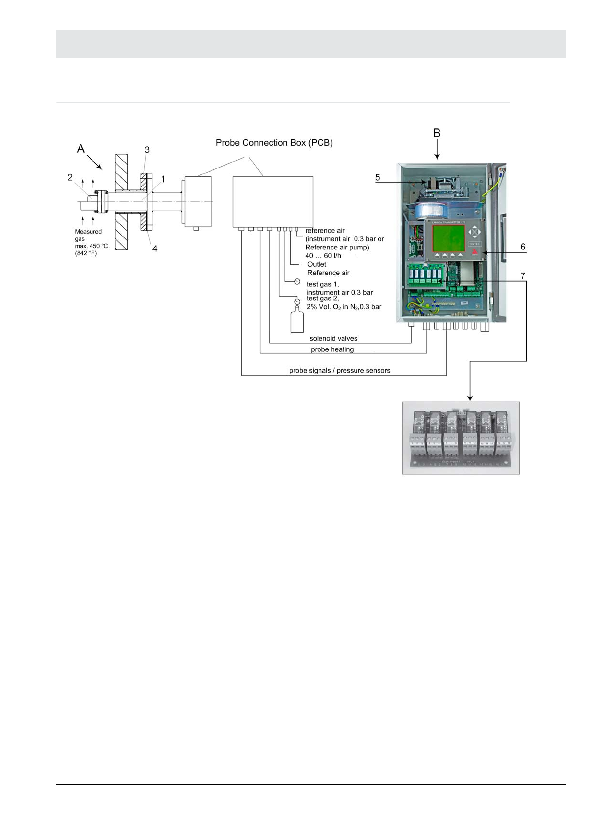
3.1 LT2-K LS2-K Structure in Principle
Fig. 3-1 LT2 LS2-K system components.
1 Pre-filter type 650R2055
2 Counter flange DN65PN6 type 655R0179/0180
3 Lambda Probe LS2-K with semi-automatic calibration unit type 656R1030/1031/1032
4 Probe connection box (PCB)
5 Connection for offset/test gas calibration – 0.3 bar instrument air, test gas for example:
3 vol. % O2 200 ppm CO 100 ppm H2 in N
6 Outlet port reference air
7 Reference air inlet, pressure reducer (on site) instrument air 0.3 bar or reference air pump 40 ... 60 l/h
8 Probe heater
9 Probe signal and pressure sensor
10 Flange seal Klinger Sil C-4400 type 655P4209
11 Measuring gas max. 400 °C/752 °F
Lambda Transmitter LT2-K type 657R102/103/104 in version 3K semi-automatic calibration
• A = in Wall mounting housing
In the case of the design with semi-automatic calibration device, the instrument air for offset
adjustment and the test gas must be connected to the probe by hand, one after the other, and
the necessary quantity must be set as well.
Pressure sensors are installed in the probe connection box and included in delivery.
A pump unit for reference air is available on request as an option if instrument air is not available.
2
NOTICE
A pump unit for reference air is necessary only if instrument air is not available!
11
Page 13
3 Technical Description
3.2 LT2-K LS2-KV Structure in Principle
Fig. 3-2 System overview LT2-K LS2-KV
A Complete probe with counter flange and PCB
B LT2-KV Lambda Transmitter in wall mounting housing IP65 with integrated reference air pump (option),
type 657R102, steel sheet
1 LS2-KV Lambda Probe with fully automatic calibration unit type 650R2050/2051/650R2052
2 Sintered metal pre-filter type 650R2055
3 Counter flange DN65PN6 type 655R0179/0180
4 Flange seal Klinger Sil C-4400 type 655P4209
5 Reference air pump (option) type 657R1060, only necessary if there is no instrument air available.
6 Display and Operating Unit
7 Relay module, option for fully automatic calibration
With the fully automatic calibrating unit, the instrument air (test gas 1) and the test gas (test
gas 2) can be permanently connected to the probe at 0.3 bar upstream pressure.
12
Page 14

3 Technical Description
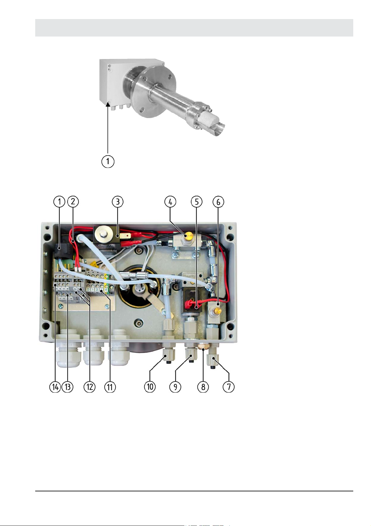
3.3 LS2-K / LS2-KV Lambda Probe
The wiring between the LS2-K / KV Lambda Probe and the LT2-K Lambda Transmitter is done
with conventional, screened cables over terminal blocks; see the wiring diagram in chapter
10.2 Connection Diagram for LT2-K/LS2-K (semi automatic calibration)10.3 Connection Diagram for LT2-KV/LS2-KV (fully automatic calibration)
1 Probe connection box (PCB)
Fig. 3-3 Lambda Probe LS2-K with semi-automatic
calibration
1 Absolute pressure sensor
2 Differential pressure sensor
3 Throttle for calibration gas
4 Throttle for reference air
5 Stop cock for calibration gas
6 Hose connection for test gas
(instrument air 0.3 bar)
7 Air outlet
8 Hose connection for reference air
(instrument air 0.3 bar)
9 Electrical connection probe to LT2
probe connection
10 Electrical connection
absolute pressure sensor to LT2,
analogue input 2
11 Electrical connection
differential pressure sensor to LT2
analogue input 1
Fig. 3-4 Interior view of probe connection box LS2-K with semi-automatic calibration
13
Page 15
3 Technical Description
Fig. 3-5 Lambda Probe LS2-KV with connection
for fully-automatic calibration
1 Probe connection box (PCB)
1 Absolute pressure sensor
2 Differential pressure sensor
3 Solenoid valve 2 (shut-off valve)
4 Throttle for calibration gas
5 Solenoid valve 1 (shuttle valve)
6 Throttle for reference air
7 Hose connection for reference air
(instrument air 0.3 bar)
8 Outlet for reference air
9 Hose connection for test gas 1
(instrument air 0.3 bar)
10 Hose connection for test gas 2
(test gas 0.3 bar)
11 Electrical connection of probe
12 Electrical connection of
solenoid valves
13 Electrical connection of
differential pressure sensor
14 Electrical connection of absolute
sensor
Fig. 3-6 Interior view of probe connection box Lambda Probe LS2-KV with fully-automatic calibration
14
Page 16
3 Technical Description
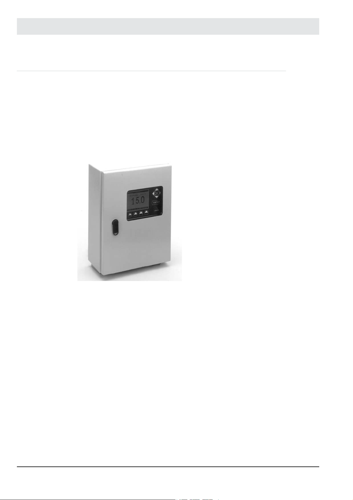
3.4 LT2-K Lambda Transmitter
The LT2 Lambda Transmitter is the analysing unit for the LS2-K Lambda Probe. It contains all
the components required in order to operate the LS2-K Lambda Probe and to evaluate the
measurement signal. It also has additional analogue and digital inputs and outputs for sending
out measurement signals and for operating, status and limit value messages as well as serial
interfaces for connecting to a PC and for connecting to other LAMTEC devices. A universal
BUS interface for connecting to customers control systems is available as an option.
The following basic design is available:
• Wall-mounted housing made of sheet steel, lockable door at the front with impact-resistant
inspection window, IP65
Fig. 3-7 LT2 Lambda Transmitter in wall-mounted housing
in the following variant:
-Semi-automatic calibration and Display and operating
unit type 657R102
15
Page 17
3 Technical Description
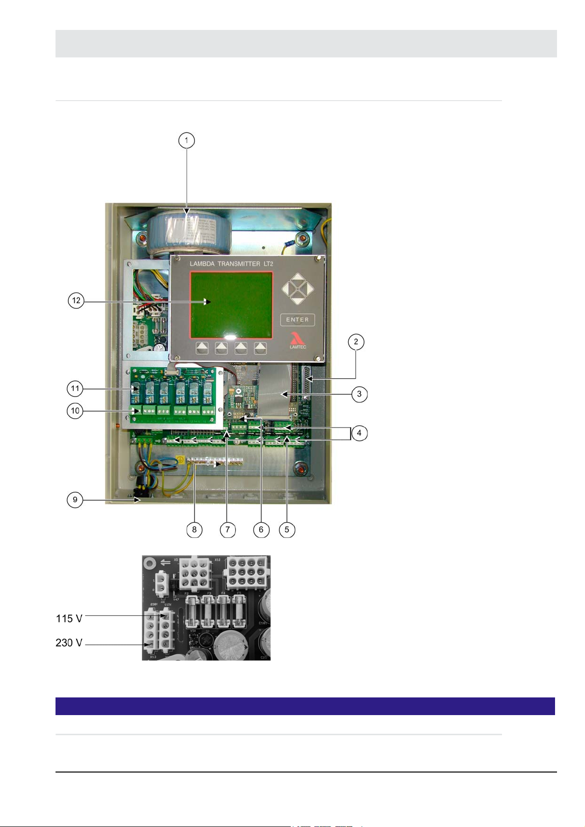
3.5 LT2-K Lambda Transmitter Type 657R102 with Display and Operating Unit
1 Transformer probe and elec-
tronic
2 Connection for Remote-Dis-
play-Software (Option)
3 Connecting cable with plug for
display and operating unit
4 Electrical connections
5 BUS-interface alternative
LAMTEC SYSTEM BUS
(CAN-BUS)
6 Operating mode display
multifunction push button
maintenance switch
7 Monitor output
8 Protective earth terminal for
cable screening
9 Mains connection (plug)
10 Terminal bar x2
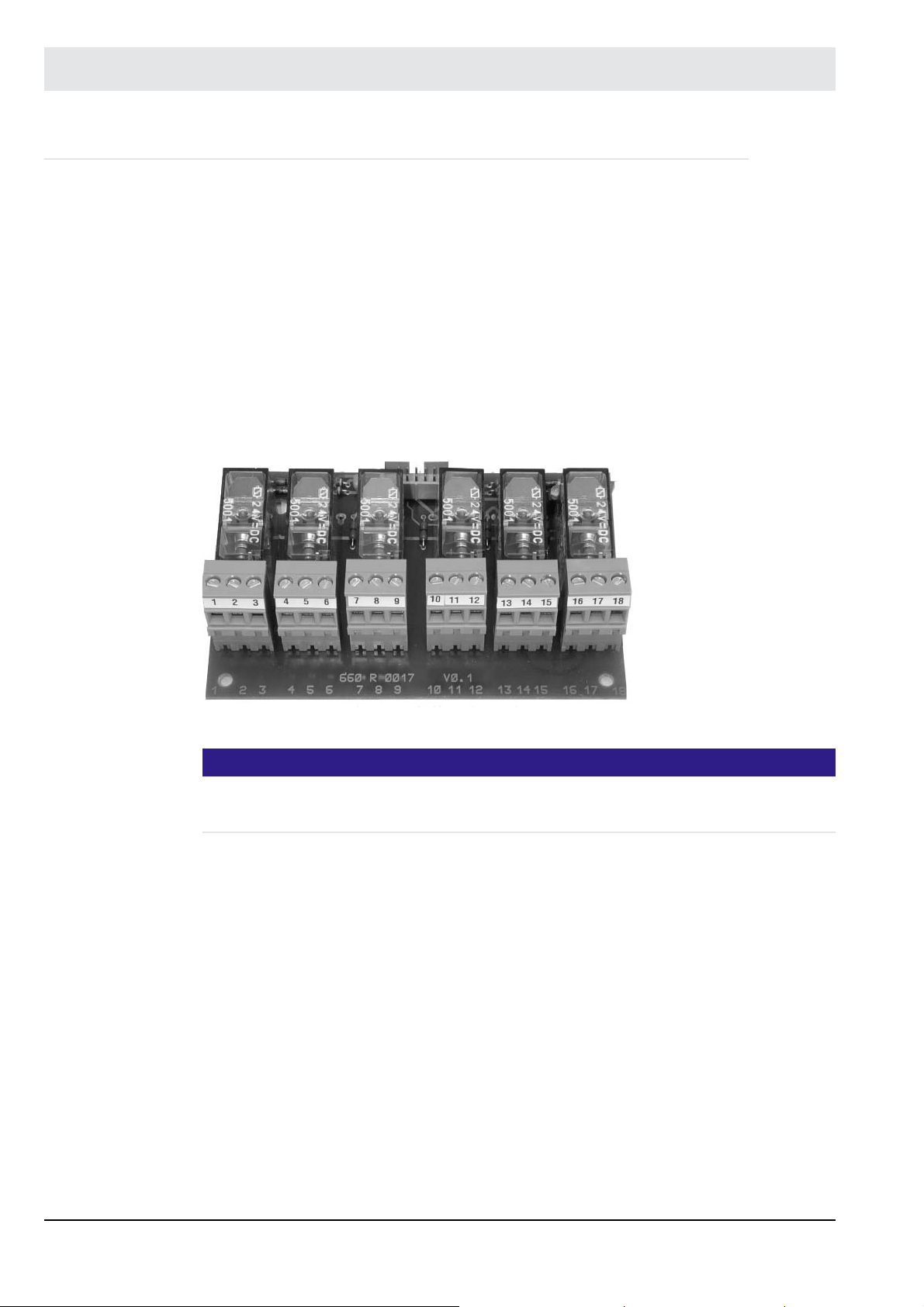
11 Relay module type 660R0017
12 Display and operating unit
Fig. 3-8 Lambda Transmitter LT2-K Type 657R102
Accessible after removing the front
panes with the main switch
POWER.
Fig. 3-9 Selection of the power supply
NOTICE
Fuse replacement F1/F3 when changeover 230/115 VAC necessary !
16
Page 18
3 Technical Description
Fig. 3-10 Connector for power supply
NOTICE
The dimensions of the wall mounting housing changes with the selection of the option ’with
reference air pump’.
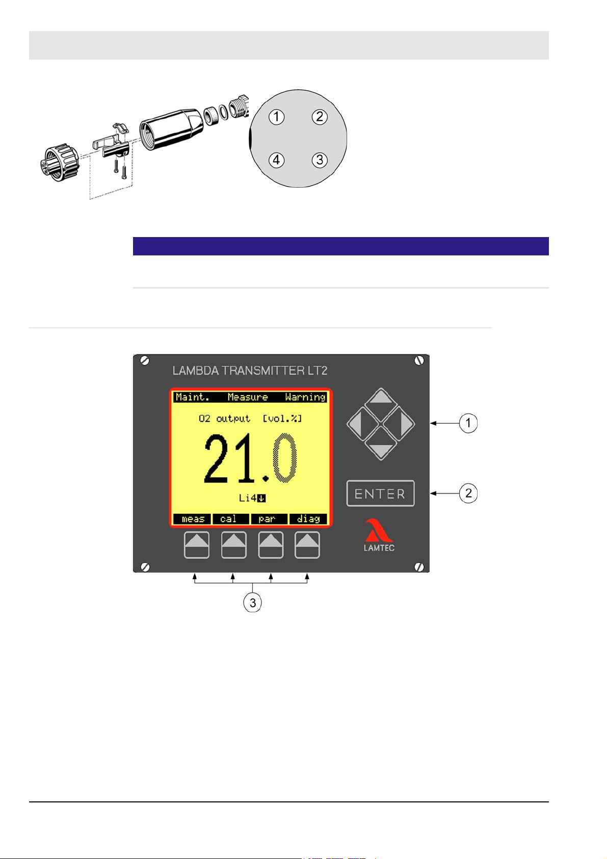
3.6 Display and Operating Unit
1 - L
2 - N
3 -
4 - PE
Fig. 3-11 Connector
1 = Cursor keys
2 = ENTER key
3 = Menu keys
Standard for LT2-K in wall mounting housing type 657R102
17
Page 19

3 Technical Description
3.7 Cold-start Delay
Coldstart delay is used for suppressing incorrect measured values while the probe is heating
up. A cold start delay is activated always after ’Power off’ or the replacement of a probe.
The cold start delay can be aborted at any time:
• by using the multi-function pushbutton
• by the display and operating unit (optional), see separate publication
• by using the remote display software, see separate publication
During the cold start delay or in fault condition the following values are output:
• a default value (factory setting of O
• the ’current measurement value’ (factory setting parameter 362)
The internal resistance of the zirconium dioxide measuring cell is monitored during the cold
start delay. It is only allowed to measure at the end of a specified time if the value is below a
threshold value of 200 Ω.
3.8 Analogue Outputs 0/4 … 20 mA, 0/2 … 10 V
2
0 Vol. %, parameter 361)
by plug-in cards on processor card of LT2-K (max. 4) – can be plugged in at any time
• Type 657R0050 non-floating (1 channel)
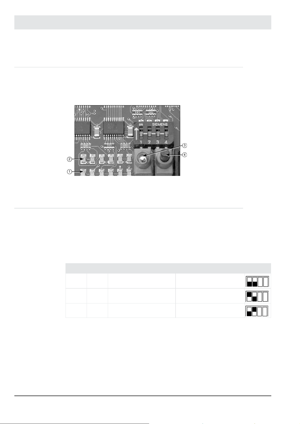
Fig. 3-12 Analogue output card Fig. 3-13 X-Jumpers for voltage output 0/2 ... 10 V
Y- Jumpers for current output 0/4 ... 20 mA
The jumpers switch only the hardware between current output and voltage output
The selection of 0 ... 20 mA or 4 ... 20 mA and 0 ... 10 V or 2 ... 10 V is set in parameter 531.
Type 657R0051 is floating with a maximum potential difference of 20 V (only possible with
output 1 and output 2).
Fig. 3-14 plug in card for floating
output type 657R0051
18
Page 20
3 Technical Description
3.9 Digital Outputs
Parameter group 1030 to 1099
Digital output 1: Via internal relay (1 switch over) to LT2supply section
Digital output 2 to 7:
type 660R0857
(optional)
The outputs can be configured arbitrarily via the (optional) display and operating unit and the
Remote Display Software. (parameter 1030 ... 1099)
electronics
1 ... 48 VDC/AC, 3 A
as standard
0 ... 230 VAC, 2 A
Via internal relay module
6 relays (1 switch over), switching capability
max. 230 VAC, 4 A
alternative (on request)
Fig. 3-15 Relay module type 657R0857
NOTICE
To avoid EMC faults shield the branch lines of the relay modules.
When using unshielded cables loop them twice trough the provided ferrite ring.
Options for LAMTEC Combination Probes
– Semi-automatic calibration (available for probes with attribute ’K’ )
– Pump for reference air (available for probes with attribute ’K’ and ’Ex’)
– Purging unit in combination with bypass tube (available for probes with attribute ’HT’)
– Purging of the preliminary filter (available for KS1D-KA and KS1D-KAF)
– Automatic regeneration of the ZrO2 measuring cell by short feeding with air for biomass
19
Page 21

3 Technical Description
3.10 Analogue Inputs (Optional)
Parameter groups 570 ... 609
By plug-in card on the electronic unit of the LT2-K power supply (max. 2)
• Analogue input card 0/4 ... 20 mA type 663P6001
• Analogue input card 0/4 ... 20 mA with 24 VDC supply for transmitter for LT1/LT2
type 663P6002
• Analogue input card for potentiometer 1 ... 5 ktype 657P6000
• Temperature input for Pt100
measurement range alternatively 0 ... 320 °C or 0 ... 850 °C (must be specified by order)
type 657R0890
• Additional pressure sensors for:
– absolute pressure
– differential pressure on request
– other modules on request
3.11 Digital Inputs
Parameter group 1170 to 1249
8 digital inputs to LT2 supply section electronics, 24 VDC, 6 mA either referenced to instrument potential or floating (see chapters 10.1 Electrical Connection to 10.4 Electrical Connec-
tion), arbitrarily configured via (optional) display and operating unit and service and diagnostic
software.
20
Page 22
4 Commissioning/Decommissioning
4 Commissioning/Decommissioning
4.1 Display and Operating Unit of the LT2-K Lambda Transmitter
The LT2's operation and the display of measured values, operational and error messages take
place by the (optional) display and operating unit, or by a PC in combination with the Remote
Display Software. The LT2 itself has only limited operating capabilities, which do not allow LT2
to display or process all the functions necessary for operation, maintenance and servicing.
1 Display of operating
mode
2 Warning /
Fault display
3 Maintenance switch
4 Multifunction key
Fig. 4-1 Internal display and operating elements on the processor
board
4.2 Monitor Output
The monitor output (terminals 31 (-) and 32 (+)) makes it possible to connect a multimeter for
example. The device indicates the following values by the monitor output:
–O2 measured value
– Probe voltage [U]
– The measuring cell's AC internal resistor [Ri]
DIP switch processor card
SW 1 SW 2 Monitor output function
OFF OFF O2 measured value 0 ... 2.5 V = 0 ... 25 % vol O
ON OFF O2 probe voltage (U-O2) 0 ... 2.5 V = 0 ... 250 mV
OFF ON O2 cell’s internal resistance 0 ... 2.5 V = 0 ... 250
Input resistance of the connected measuring device greater than 10 k.
2
21
Page 23
4 Commissioning/Decommissioning
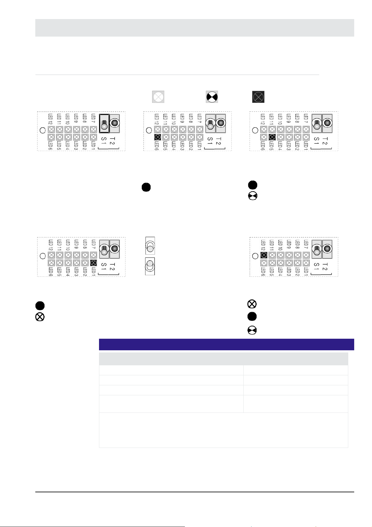
4.3 Internal Display and Operating Elements
Multifunction key T 2
Maintenance switch S 1
Legend: LED
is off
Operation (green) LED 6 Operating mode (green) LED 5
Operation Measurement
Maintenance mode off
Maintenance mode on
flashes
lights up
Calibration
Offset compensation (flashes slowly)
With test gas/comparative measurement (flashes quickly)
Maintenance (orange) LED 1 Warning/fault (red) LED 12
Maintenance mode active
Normal operation
NOTICE
Function Key operation
Toggle the displayed warning/ fault Press briefly
Reset the displayed warning/fault Press for longer than 3 sec*
Abort cold-start Press for longer than 3 sec**
Trigger an offset calibration to ambient air Press key for longer than 3 sec
* Some warnings and faults cannot be reset if the error is still present or the routine is
still running.
** If at least one warning or fault is still present, the key must be pressed for longer than
6 seconds.
No warning / fault
At least one warning present
At least one fault present
during measurement**
22
Page 24
4 Commissioning/Decommissioning
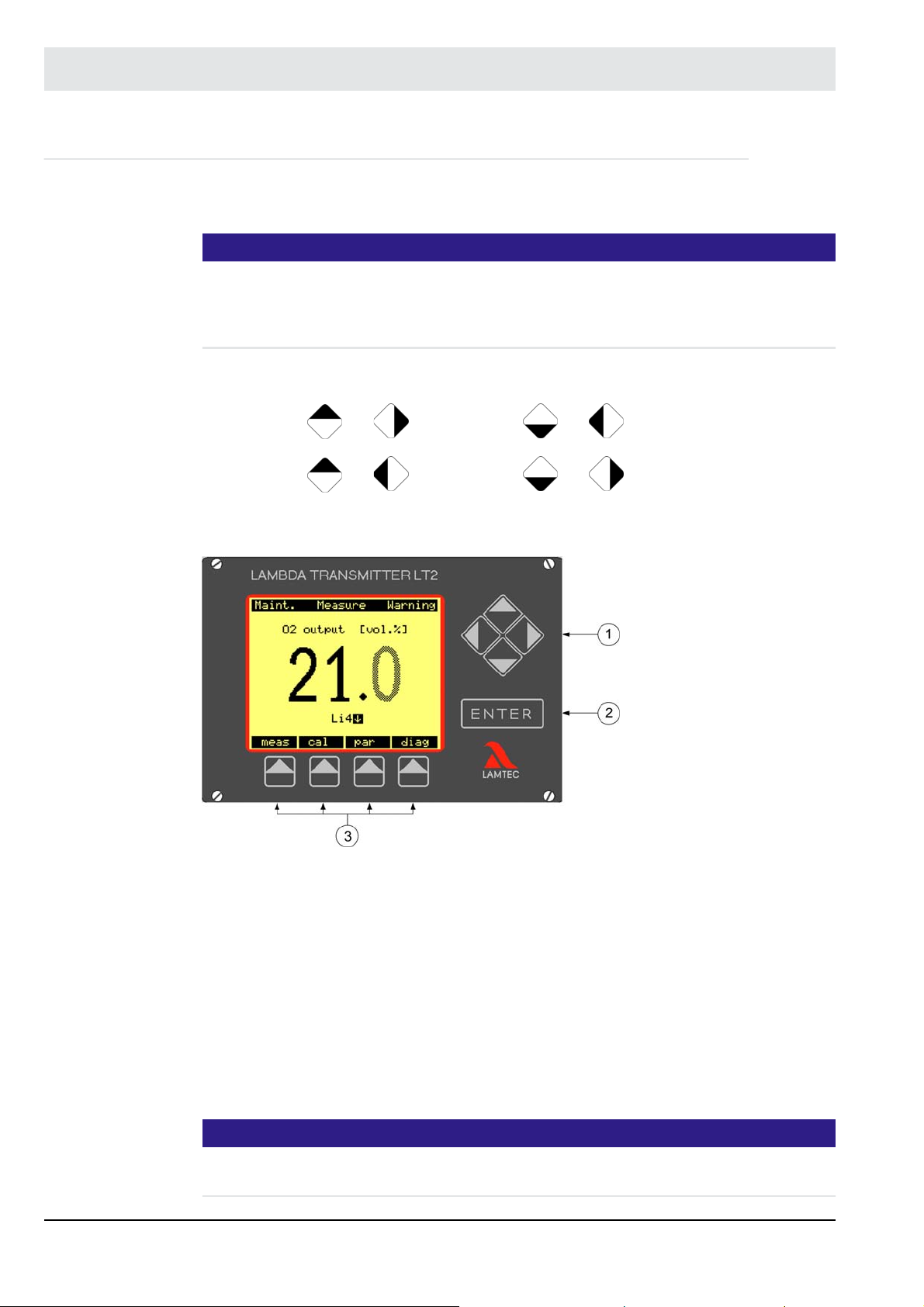
4.4 Display and Operating Unit Type 657R0831 (Option)
Fig. 4-2 Display of LT2-K with key assignment shows the display of the LT2 Lambda Transmitter. It consists of a LCD display, the cursor keys, the ENTER key, and the menu keys.
NOTICE
- The cursor keys are used to select measurement values, parameters or functions in the
visual area of the display. The keys are also positioning the cursor for entering and editing.
- The ENTER key activates, confirms and ends the editing mode.
- The menu keys are assigned to the menu which is shown in the display
For adjusting brightness and contrast use the cursor keys:
contrast +: + contrast -: +
brightness+: + brightness -: +
The menu keys have the following functions (from left):
measurement [meas] calibration [cal] set parameter [par] diagnoses [diag].
Fig. 4-2 Display of LT2-K with key assignment
1 = Cursor keys
2 = ENTER keys
3 = Menu keys
The menu keys are given in the terms which describe the functions of the LT2 Lambda Transmitter written in an abbreviated form.
Menu keys meas: measurement (measure)
cal: calibration (calibration)
par: parameter setup (parameterise)
diag: diagnosis (Diagnostics)
NOTICE
Only limit values which are activated in parameter 930/940/950/960 are displayed (release
level ’Service’).
23
Page 25
4 Commissioning/Decommissioning
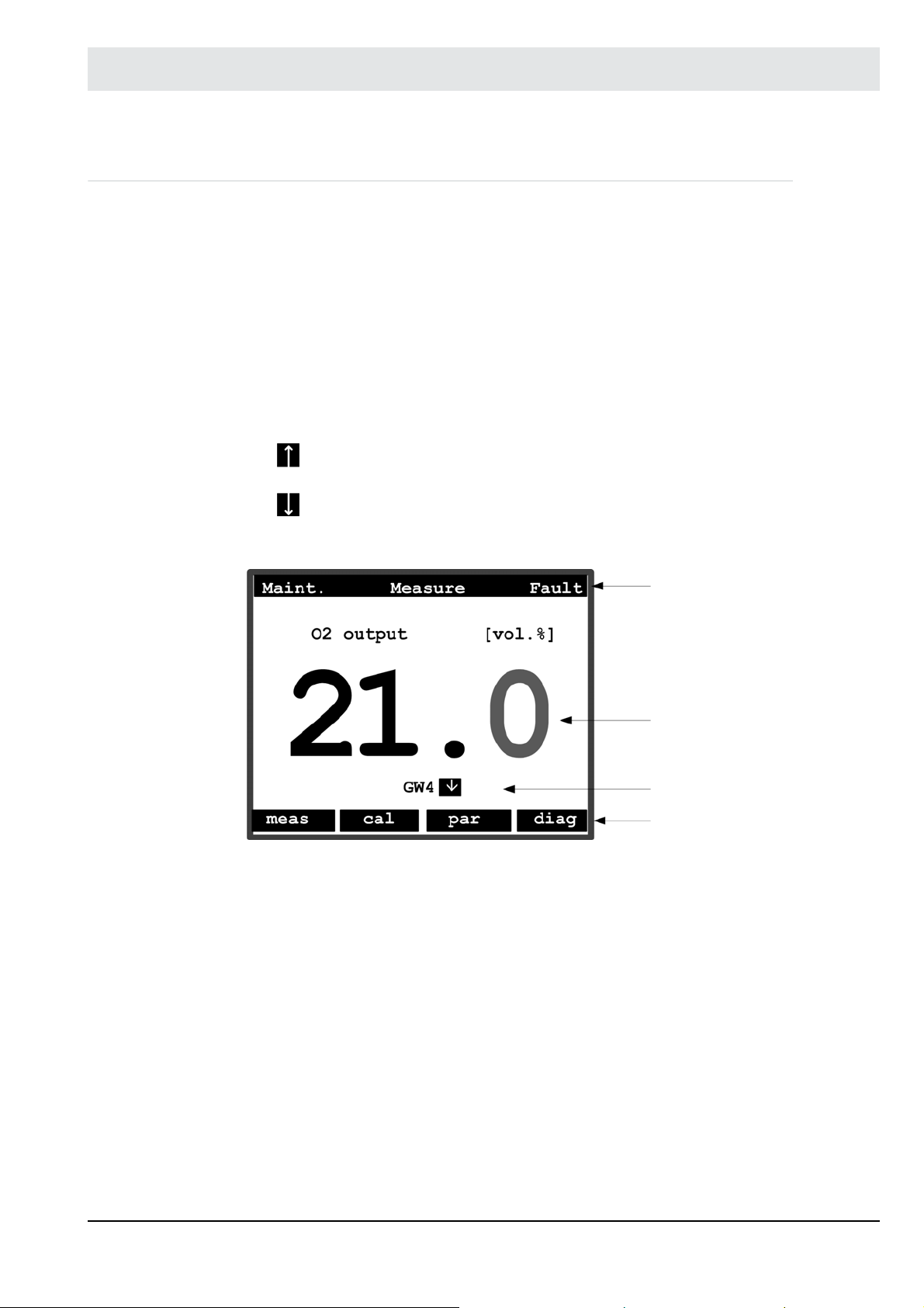
4.4.1 Display
The display is devided into four areas: (see Fig. 4-3 Arrangement of the display):
1. The status line at the top of the display shows the following:
• On the left side, whether the maintenance mode is activated or not
• In the centre, the current operating status
• On the right, if warnings or faults are present in the system
• Faults are also indicated with the flashing of the status light.
2. The measurement value, shown in the centre of the display area
3. The limited value display shows the following
GW = limit value activated
limit value exceeded
value below the limit value
4. The menu items to which the menu key below is allocated.
Fig. 4-3 Arrangement of the display
1 Status row
2 Measurement value
3 Limit value
4 Menu row
24
Page 26
4 Commissioning/Decommissioning
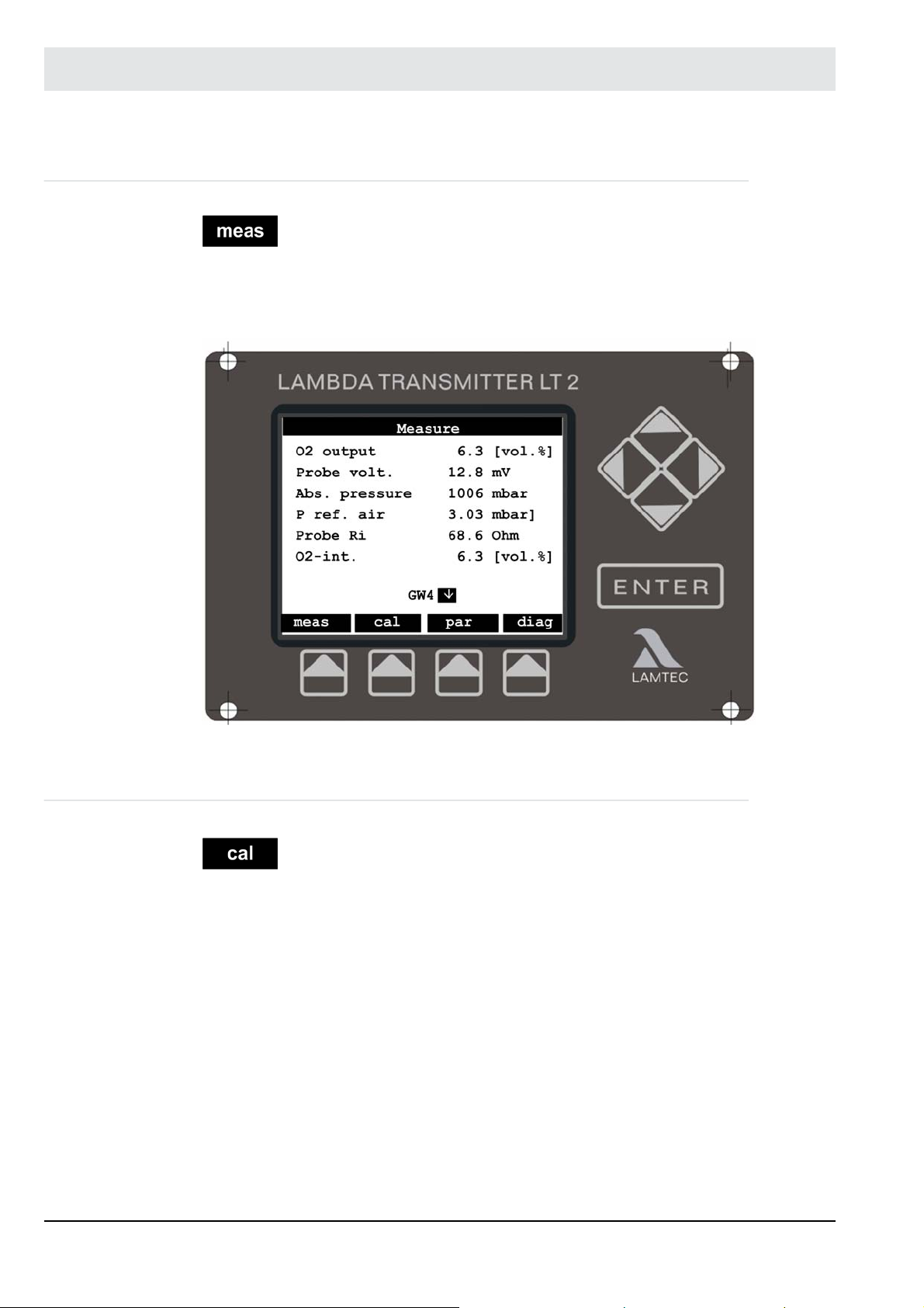
4.4.2 Menu Function 'meas'
When pressing the [ meas ] the display switches to a large representation of the measure-
ment value that has been selected with the cursor keys (up, down) (see 4.4 Display and Op-
erating Unit Type 657R0831 (Option)). Pressing the [ meas ] key repeatedly switches the
display back to a listing of all the measured values.
Fig. 4-4 LT2 display meas
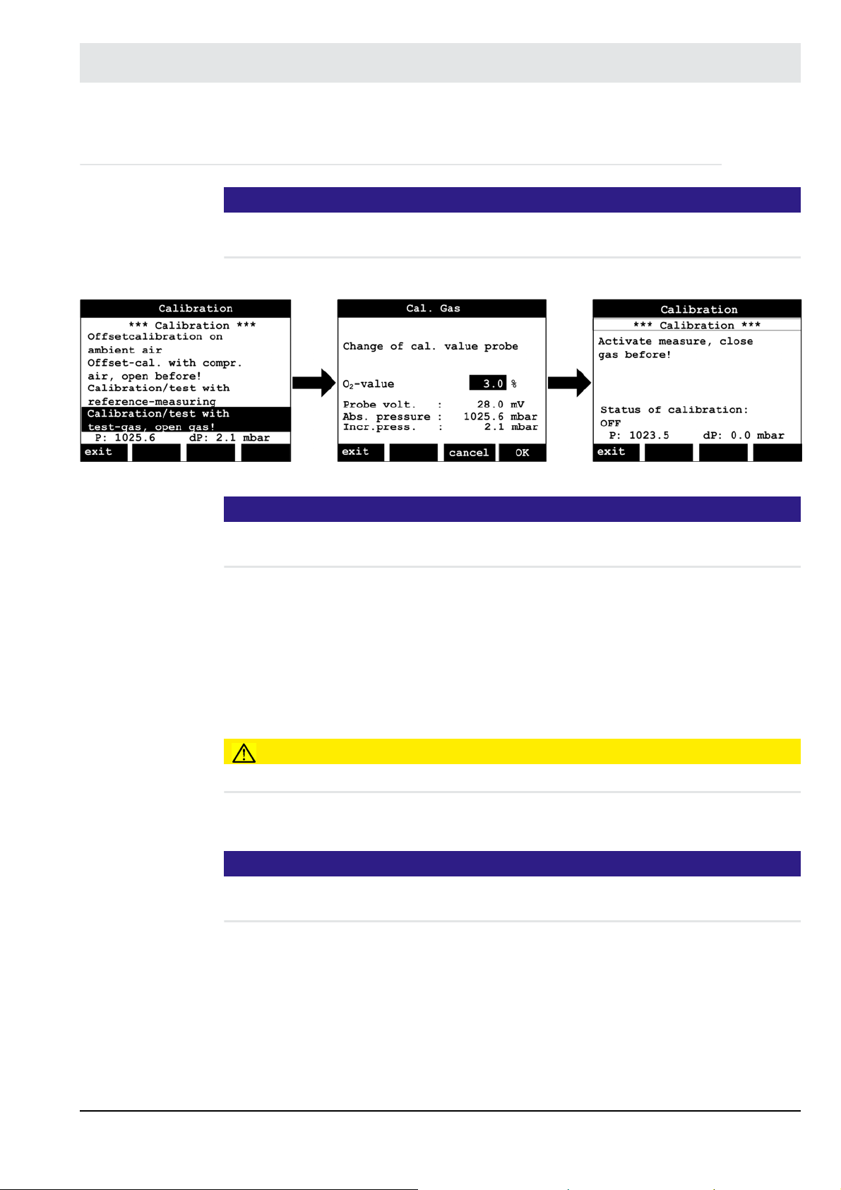
4.4.3 Menu Function 'cal'
Pressing the [cal] menu key, “start calibration” appears on the display. When the calibration
is activated 4 calibration functions are available Fig. 4-5 Calibration functions:
• Start offset calibration in ambient air (see chapter 4.7.1.2 Performing an offset calibration
to ambient air)
• Start offset calibration with compressed air (for semi-automatic calibration open the shutoff valve in the probe connection box, see chapter 4.7.1.3 Performing an Offset Calibration
with Compressed Air).
• Start calibration with a comparative measurement (manual calibration function)
• Start calibration with test gas (for semi-automatic calibration open shut-off valve in the
probe connection box)
Select the required calibration function by the up/down cursor keys. Confirm the selected function with the ENTER key. This triggers the calibration procedure. The automatic calibration
mode can be interrupted by the menu function ’Break’ calibration before end; back to measure’.
25
Page 27

4 Commissioning/Decommissioning
During manual calibration the calibrated value can be change by the menu function ’Change
of calibration value probe LS2-K/LS2-KV’.
Fig. 4-5 Calibration functions Fig. 4-6 Menu functions
After calling up this menu function, the amendment procedure in the displayed sub-menu can
be terminated with the [ cancel ] menu key. Alternatively confirm the O
menu key.
Quit manual calibration with ’Break calibration before end’ (the O2 value is retained).
value with the [ OK ]
2
NOTICE
The manual calibration mode remain active for a maximum of 15 minutes This is followed by
switching automatically back to the measurement mode.
If the [ cal ] is called up during cold start, the cold start can be aborted.
A substitute O2 value is displayed during calibration procedure. Measurement or display of a
meaningful O2 value is only possible in the operational mode, i.e. after completing the calibration.
NOTICE
Check parameter 151 after the offset calibration.
The value must be 40 1 respectively 15 1.
Recommended test gas: 3 % oxygen 97 % nitrogen
26
Page 28

4 Commissioning/Decommissioning
4.4.4 Menu Function 'par'
After calling up the [ par ] menu the menu to set parameters opens.
Fig. 4-7 Parameter menu
Access to the parameter menu is divided into the following authorization levels:
• Operation level
• Customer level requires a password
• Service level requires a password
• Factory level requires a password
NOTICE
The password for the customer level can be individually set by the customer, (see chapter
4.4.12 Customer Password Input).
The display shows the current access level. The following functions can be chosen from the
menu row:
• [ exit ] returns to the start menu
• [ psw ] provides the change of the release level by password
• [ view ] shoes the parameter settings. All parameter are shown regardless of the release
level.
• [ change ] provides the changing of the parameter settings. Only parameters which are
accessible with the actual access level are displayed.
NOTICE
More than 3000 parameters can be changed by the different access levels.Recommendation:
Use the function [ change ] to avoid confusion.
Fig. 4-8 Password entry
27
Page 29

4 Commissioning/Decommissioning
4.4.5 Menu Function 'psw'
[ psw ] calls up the password input menu. The authorization level* is displayed. The functions
which a in the menu are described below:
• [exit] returns to the [ par ] menu.
• [ clear ] resets the access level to ’Operation’ *.
• [ ---- ] shifts to the previous letter in the alphabet.
• [ ++++ ] shifts to the following letter in the alphabet.
The up/down cursor keys act similarly to [ ++++ ] and [ ---- ]. Left/right move the input mark
along the password. Once the correct password is entered, the corresponding authorization
level is displayed and is retained on leaving the menu with [ exit ]. If no key is pressed for
some time, the access level is reset to operation level.*
4.4.6 Menu Function 'view'
[view] opens the parameter menu.
The following functions are available in the menu bar:
• [exit] returns to the menu function [par].
• [s/l] toggles between display formats:
• [group-] scrolls back one parameter group.
• [group+] scrolls forward one parameter group.
Short:
– Only the parameter number and the cur-
rent value are displayed.
Medium:
– The parameter number and the current
value are accompanied by a short
description.
28
Page 30

4 Commissioning/Decommissioning
[ group- ] changes one parameter group back.
[ group+ ] changes one parameter group forward.
All available parameter groups are listed in the appendix. The left/right cursor keys correspond
to the key-function of [ group - ] and [ group + ].
Flashing arrows in the right-hand margin show that not all parameters in a group are visible in
the display. The up/down cursor keys can be used to scroll through the parameters.
As an example, we explain below the status row shown in the Long format:
• If not all the parameters in a group are visible in the readout, this is indicated by flashing
arrows in the right-hand margin. The up/down cursor keys can be used to shift the parameters and make them visible.
• *kw*_30_____[ 12 ; 42 ]_____
The asterisks and underline characters (* and _) are fillers.
• K indicates the customer access level
(b = operation, k = customer, s = service, f = manufacturing)
• W indicates the parameter type
(write = change, read = read only).
• 30 = default value (base value in EPROM)
• [ 12 ; 42 ] is the possible range within which the parameter can be changed
For some parameters no default value and interval is available!
Display long:
– The same as Medium, but with an addi-
tional parameter status line.
29
Page 31

4 Commissioning/Decommissioning
4.4.7 Menu Function 'change'
[ change ] allows parameter values to be amended. The menu bar for the sub-menu is the
same as the [ view ] menu (see chapter 4.4.6 Menu Function 'view').
Unlike this the parameter which should be changed is displayed inversely (bright letters on
dark ground). Select the parameter with the cursor keys (up, down). Confirming with the
ENTER key activates the edit mode. The value flashes during edit mode.
A selected parameter is displayed in three different ways:
The parameter can be changed
The parameter cannot be changed
Edit mode is active
The parameter value can be changed with the cursor keys up/down (left/right for multi-digit
values). Menu row functions:
• [ esc ] returns to the [ change ] menu without saving the changed value in the parameter.
• [ dflt ] sets the default value (factory settings).
• [ OK ] accepts the changes value and returns back to the [ change ] menu or to the
[ ENTER ] menu.
This leads back to the [ change ] menu. Other parameters can be changed.
30
Page 32

4 Commissioning/Decommissioning
4.4.8 Menu Function 'diag'
On pressing the [diag] key, the display switches to warnings and faults. Use the up/down cursor keys to select individual warnings or faults, or limit values.
NOTICE
Limit values are displayed only if they are also activated by parameters 930/940/950/960 (service level).
The selected and inversely displayed warning or fault can only be acknowledged or reset by
the ENTER key.
Fig. 4-9 Displaying faults and warnings
NOTICE
Some faults or warnings cannot be reset by acknowledgement. The cause of the fault or warning must be removed.
If a limit value is selected and confirmed with the ENTER key, the display switches to the limit
value menu.
Fig. 4-10 Limit value menu
31
Page 33

4 Commissioning/Decommissioning
Description:
Limit value 1 is set by parameter to O
Switching point: exceeding 10.0% per volume O
short fall 3.0 % per volume O
Recent O2 measurement value 6.7 % per volume O2
The limit value is not set.
measurement value.
2
2
2
GW2
GW3
Limit value2 has responded. The value is higher than the limit.
Limit value3 has responded. The value is lower than the limit.
Select one limit value after another with the cursor keys. As soon as ’Manual’ or ’Acknowledge’
is selected, the limit value can be reset. Press ’exit’ to leave the limit value menu.
4.4.9 Limit values display and resetting
The current state of the limit values and the reset of the limit values are processed in three
display of the limit values group.
Parameters: 910 ... 9144
The parameters Limit Value 1, Limit Value 2, Limit Value 3 and Limit Value 4 indicate the current settings and state of the limit values.
Parameters: 914 ... 917
The Parameter Reset Li 1, Reset Li 2, Reset Li 3 and Reset Li 4 trigger the reset of the limit
values outputs if the operating modes MANUAL RESET or ACKNOWLEDGE are selected.
To reset a limit value enter ’Reset’ in the respective parameter. In MANUAL RESET mode a
reset is only possible if the monitored reference value is within the limits of Li min. and Li max
Content of Parameters 910 ... 917
0 = Off
1 = enable
2 = acknowledged
3 = disabled.
Off: This indicates either that the limit value in question is not in use or the monitored reference value is within the limits of Li min. and Li max.
Enable: If the display shows ’enabled’ for a limit value the monitored reference value is outside range between Li min. and Li max.
Acknowledged: If the display shows ’acknowledged’ for a limit value the monitored reference
value is outside of the good condition range and the exceeding of the limit value has been acknowledged already.
Disable: The limit value is not parameter set or the limit value is disable via digital inputs or
operating mode (par. 967)
With software version 1V33 and higher the limit values can be deactivated by the digital outputs or by the operating mode (parameter 967).
• Limit value conditions parameter 910…913: 0 = off, 1 = set, 2 = acknowledged,
3 = inactive.
32
Page 34

4 Commissioning/Decommissioning
The condition ’inactive’ is displayed, if the limit value is not set in the parameter or if the
limit value is deactivated by the digital inputs or the operating mode (parameter 967).
• All limit values can be deactivated together depending on the operating mode.
The behaviour can be set in parameter 967 in service level.
Parameter values: 0 = never, 1 = cold start (default), 2 = cold start + maintenance, 3 = no
measurement.
Faults and warnings have no influence of the limit values!
• Each limit value can be deactivated by the function ’Deakt. GWx by the digital inputs
(x={1,2,3,4}).
4.4.10 Display of the Limit Value Crossing
Fig. 4-11 Display LT2 limit values
The limit values are displayed by means of the soft-keys.
When limit value parameters 930/940/950/960 are activated in the access level ’Service’, the
display shows Li1, Li2, Li3 and Li4 depending on the currently activated limit value.
Exceeding the limit values:
Li 1
Li 2
= Li1 has been exceeded (higher than limit value)
= Li2 has been exceeded (lower than limit value)
33
Page 35

4 Commissioning/Decommissioning
4.4.11 Brightness, Contrast and Language
The parameter group ***Display*** controls the LT2 Lambda Transmitter's display and operating unit with the following parameters:
• P 970 Contrast
Adjust the display and operating unit’s contrast.
• P 971 Brightness
Adjust the display and operating unit’s background brightness
• P 972 Language
Select the display language.
NOTICE
Only 2 different languages are available simultaneously. If a language is missing in the language list, a software update may be necessary (Flash).
34
Page 36

4 Commissioning/Decommissioning
4.4.12 Customer Password Input
The password for the customer level can be set individually.
To enter a new password, at least customer access level must be set.
Enter the new password in parameter 1472 (see Fig. 4-12 Password input).
NOTICE
The system accepts the password a few seconds after the input.
The display shows the new password as ’####’. Reading this password is not possible.
Fig. 4-12 Password input
NOTICE
The factory setting of the password is ’0000’.
This corresponds to the default settings of password input.
The customer access level can be activated by switching briefly to password input and leaving
it again without making any changes.
NOTICE
The customer gets the password for service access level by a letter. Only trained personnel
may get this password. OEM customers have their own company-specific password. This is
the same in all LAMTEC devices.
35
Page 37

4 Commissioning/Decommissioning
4.5 Menu Overview
4.5.1 LT2-K Calibration Menu
Fig. 4-13 Overview of the calibration menu cal
36
Page 38

4 Commissioning/Decommissioning
4.5.2 LT2-K Diagnosis Menu
Fig. 4-14 Overview diagnosis (diag)
37
Page 39

4 Commissioning/Decommissioning
4.5.3 LT2-K Measurement Menu
Fig. 4-15 Overview measurement menu (meas)
38
Page 40

4 Commissioning/Decommissioning
4.5.4 LT2-K Parameter Menu
Fig. 4-16 Overview parameter menu (par)
39
Page 41

4 Commissioning/Decommissioning
4.6 Factory Settings
4.6.1 Device Configuration
(unless otherwise specified in the order)
Measurement range: 0. .. 30 % volume of O
2
Resolution: 0.1 % volume of O2 in the range of 0 ... 18 % volume of O2
1.0 % volume of O2 in the range higher than 18 % volume of O
Probe temperature: 1000 K (parameter 141)
Analogue output 1: 4 ... 20 mA = 0...10 % volume of O2 by parameter 531
0 ... 20 mA adjustable
Load: 0 ... 600
– Measurement range by parameters 532 and 533 freely configurable
– Relay outputs closed circuit principle
Relay output 1: Group fault message
Relay output 2: Warning and maintenance
Relay output 3: Measurement
Relay output 4: Limit value 1
Relay output 5: Limit value 2
Relay output 6: LS2-KV calibration
Relay output 7: LS2-KV calibration
– Limit values
Limit value 1: Switched OFF
Limit value 2: Switched OFF
Limit value 3: Switched OFF
Limit value 4: Value falling below < -5 mV,
Trigger delay of 3 s
Reset mode ’automatic’ (for monitoring the probe; air value)
– Digital Inputs
Input 1: Reset fault/warning
Input 2: Reset limit value indications
Input 3: Maintenance ON/OFF
Input 4: PID controller OFF
Input 5: Fully-automatic, combined calibration
Input 6: Fuel 2 (gas)
Input 7: Fuel 3
Input 8: Fuel 4
(1)
(1)
(1)
– RS 232 interface: Device 1
9600 Baud
Parity none
(1)
Parameter 836 - service level - must be set to ’digital inputs’.
without signal specification - domestic fuel EL.
2
4.6.2 Jumpers
see chapter 10.5 Jumpers
40
Page 42

4 Commissioning/Decommissioning
4.7 Measurement Start-up
NOTICE
When installing the probe and during subsequent operation, it is necessary to make sure that
the probe does not get into contact with oil, grease or with agents used to clean the tank.
This belongs to the cell and the connection area!
Poisoning or contamination of the probes is indicated by a potential difference across the air
gap of < -20 mV or > -30 mV. Furthermore, once installed the probe must always be in operation. This will prevent moisture from collecting on the measurement cell which can lead to
measurement errors and to the destruction of the probe!
CAUTION!
The temperature of the aluminium connection housing, should not be higher than +60 °C/
140 °F, because of internal built-in pressure sensors. If necessary use a longer probe with an
intermediate flange.
Do not insulate the counter flange and the housing.
• Install and setup probe
– Mounting flange in design without purge unit DN65 PN6 (through hole 80 mm/
3.15" in)
– Mounting flange in design with purge unit DN80 PN6
(through hole 125 mm/4.921" in)
CAUTION!
Do not forget the gasket between counter and probe flange.
Mounting position probe horizontal Mounting position probe vertical
Fig. 4-17 Mounting position of probe
1 Connection housing (temperature max. 60 °C/140 °F)
2 Baffle plate
3 Flow direction of the flue gas (temperature max. 450 °C/842 °F)
41
Page 43

4 Commissioning/Decommissioning
4.7.1 Measurement with LS2-K
1. Connect the probe electrically and pneumatically, see connecting diagram chapter 10.1
Electrical Connectionand 10.4 Electrical Connection.
2. Supply reference air connection and calibration gas connection with instrument air of
0.3 bar.
NOTICE
If instrument air is not available use regular compressed air for air calibration. If neither instrument air nor compressed air is available proceed one of the following options:
• Switch OFF the plant and ensure that the measuring point is in ambient air.
• Remove the probe.
3. Switch on LT2.
4. Switch to MAINTENANCE alternatively by display and operating unit in the [diag] menu or
by maintenance switch S1.
Using the maintenance switch S1
MAINTENANCE mode OFF MAINTENANCE mode ON
NOTICE
The maintenance key has always priority over the software key in the [diag] menu.
• MAINTENANCE is displayed
– LED1 (orange) is ON
• Probe heats up (10 min.)
• COLDSTART is displayed
– LED5 MEASUREMENT is OFF
– LED6 OPERATION is ON
5. The probe heats up (COLD START)
NOTICE
During the COLD START the cell’s internal resistance Ri is indicated on the display and operating unit or on the monitor output.
NOTICE
The cold start delay can be interrupted from the display and operating unit or by using the multifunction keys:
• Press [cal] key an follow the menu
• Alternatively press multifunction key T2 for longer than 3 s or in warning or fault condition
press T" for longer than 6 s.
42
Page 44

4 Commissioning/Decommissioning
NOTICE
Function Key operation
Toggle the displayed warning/ fault Press briefly
Reset the displayed warning/fault Press for longer than 3 s*
Abort cold-start Press for longer than 3 s**
Trigger an offset calibration to ambient air Press key for longer than 3 during
* Some warnings and faults cannot be reset if the error is still present or the routine is
still running.
** If at least one warning or fault is still present, the key must be pressed for longer than
6 seconds.
• Watch the cell’s inner resistance and read the probe voltage alternatively by:
– Display and operating unit
– Remote Display Software
– Monitor output
measurement**
NOTICE
To read the probe voltage click [meas] key and select the Usprobe voltage on the display.
After a heating up time of 3-5 Min. the probe voltage gets stabilised to values between -5 and
-15 mV and the cell’s inner resistance (Ri probe) gets stabilised to values below 100 . If positive values are indicated in ambient air the probe has been connected reversely. Swap the
probe connections on terminal 33/34.
• After COLD START has finished the device switches to MEASUREMENT mode automatically.
43
Page 45

4 Commissioning/Decommissioning
4.7.1.1 Adjust the Amount of the Reference Air
NOTICE
Only oil-free and water-free compressed air can be used as reference air.
Recommendation: Use instrument air if available.
If neither instrument air nor compressed air is available a LT2 with integrated reference air
pump is necessary. The optional internal reference air pump type 657R060 cannot be retrofit
in a wall mounting housing for LT2 type 657R102.
Retrofitting a reference air pump is only possible with an external housing type 657R1061.
NOTICE
Reference air is monitored permanently by a differential pressure sensor which is installed in
the connection box of the LS2-K.
NOTICE
Reference air is monitored by the fault ’No reference air’. Release time: 1 h
• Calibrate the differential pressure sensor to 0.
– Therefore close thee reference air completely. Refer to the display and control unit
menu function [par], [psw], [change] (see chapter 4.4.2 Menu Function 'meas' ff.)
– Open the throttle until a differential pressure of 2 to 3 mbar has been reached (see Fig.
4-18 Display LT2).
Fig. 4-18 Display LT2
44
Page 46

4 Commissioning/Decommissioning
1 Differential pressure sensor
2 Absolute pressure sensor
3 Throttle for calibration gas
4 Throttle for reference air
5 Stopcock for calibration gas
6 Hose connection for test gas (instrument air or
test gas ca. 0.3 bar)
7 Outlet for air
8 Hose connection for reference air (instrument
air ca. 0.3 bar)
9 Electrical connection probe to LT2-K
10 Electrical connection absolute pressure sen-
sor to LT2 analogue input 2
11 Electrical connection differential pressure sen-
sor to LT2 analogue input 1
Fig. 4-19 Internal view of probe connection box LS2-K
4.7.1.2 Performing an offset calibration to ambient air
NOTICE
The probe must be removed or ambient air must be ensured at the measuring point.
• Trigger offset calibration alternatively by:
– Display and operating unit by the [cal] menu
– Remote Display Software by the [cal] menu
– Multifunction key (only with ambient air) see chapter 4.7.1 Measurement with LS2-K If
the system works properly for 20 Min. after finishing the offset calibration repeat the
calibration
Menu function
Pressing the [cal] menu key shows ’Start calibration’ in the display. After the activation of the
calibration 4 functions are available (see chapter 4.7.1.3 Performing an Offset Calibration with
Compressed Air), Use the two upper functions for offset calibration:
• Start offset calibration in ambient air
• Start offset calibration with compressed air (open stopcock in PCB)
• Start calibration with reference measurement
• Start calibration with test gas (open stopcock in PCB)
Press cursor keys up/down to select the required offset calibration.
Press ENTER key to start the selected offset calibration.
Use the menu function ’ Break calibration before end!’ to abort the calibration.
After finishing the automatic calibration procedure in ambient air the LT2 changes to MEASUREMENT mode.
Press the [exit] key to change to the indication of the measurement values.
By multi function key T2 as an alternative (with ambient air only):
45
Page 47

4 Commissioning/Decommissioning
NOTICE
Function Key operation
Toggle the displayed warning/ fault Press briefly
Reset the displayed warning/fault Press for longer than 3 sec*
Abort cold-start Press for longer than 3 sec**
Trigger an offset calibration to ambient air Press key for longer than 3 sec
* Some warnings and faults cannot be reset if the error is still present or the routine is
still running.
** If at least one warning or fault is still present, the key must be pressed for longer than
6 seconds.
• Wait until the offset calibration has finished. The flashing stops. The status line shows
’Measurement’.
Repeat the offset calibration after 20 Min. of failure free operation.
4.7.1.3 Performing an Offset Calibration with Compressed Air
during measurement**
NOTICE
If compressed air (instrument air) is available the offset calibration can be proceeded without
removing the probe. Compressed air (instrument air) of 0,3 bar must be connected to the calibration gas inlet.
CAUTION!
Open the stopcock in the PCB before clicking the ENTER key. Adjust the required rise in pressure of dP = 2 mbar by the calibration gas throttle (see Fig. 4-20 Display of offset calibration).
Fig. 4-20 Display of offset calibration
CAUTION!
Close the stopcock in the PCB after finishing the offset calibration. Measurement mode may
not be activated before closing the stopcock.
46
Page 48

4 Commissioning/Decommissioning
4.7.1.4 Perform a Calibration with Reference Measurement
Select ’Calibration/test with reference-measuring’ in the [cal] menu and confirm with ENTER.
Use the up/down cursor keys to adjust the O2 value of the reference measurement.
Confirm with [OK] key (see Fig. 4-21 Input of the calibration values).
This is valid only for O2 values smaller than 18 %.
Use the [canel] key to quit the calibration process.
Fig. 4-21 Input of the calibration values
47
Page 49
4 Commissioning/Decommissioning
4.7.1.5 Perform a Calibration with Test Gas
NOTICE
The calibration can be proceeded with test gas as an alternative to the reference measurement.
The procedure corresponds to the offset calibration with compressed air.
Fig. 4-22 Display of calibration with test gas
NOTICE
The test gas used must be free of oxidizing components such as CO, NO, etc.Oxidising components are burned at the 700 °C hot Pt electrode catalytically and distort the calibration.
Calibration with test gas
1. Disconnect instrument air of the offset calibration
2. Connect test gas with 2 … 5 Vol. % O2 in N2 and with a primary pressure of 0.3 bar at the
PCB of the LT2
3. Wait for 1 to 2 minutes after supplying test gas until the measuring value has stabilised.
4. Proceed with adjusting the O2 value to the value of the test like the calibration with reference air.
CAUTION!
Close the stopcock before activating the MEASUREMENT mode.
5. Press [exit] key to change to the display of the measurement value.
During the calibration procedure an O2 substitute value can be chosen in parameter 275.
NOTICE
The CALIBRATION mode remains active for a maximum of 15 Min. Afterwards the system
switches to MEASUREMENT mode automatically.
48
Page 50

4 Commissioning/Decommissioning
4.7.2 LS2-KV Measurement (Fully-automatic Calibration)
• Apply instrument air of 0,3 bar at the probe’s reference air connection and test gas 1 connection. Apply test gas of 2 … 5 % volume of O2 in N2 of 0,3 bar on test gas 2 connection.
CAUTION!
The test gas used must be free of oxidizing components such as CO, NO, etc. Oxidising components are burned at the 700 °C hot Pt electrode catalytically and distort the calibration.
• Switch on power
• Probe heats up (COLD START see chapter 4.7.1 Measurement with LS2-K)
• Enter the O
operating unit).
NOTICE
The O2 concentration which is entered in parameter 301 must be the same as the O2 concentration of the connected test gas. Differences caus measuring failures. because the probe is
calibrated to the specified value.
concentration of the connected test gas 2 in parameter 301 (see display and
2
• If the cold start is not aborted the LT2 proceeds a combined offset and test calibration afterwards. The probe is now in measurement condition. A manually triggered calibration
can be abandoned.
49
Page 51

4 Commissioning/Decommissioning
4.7.2.1 Adjust the Amount of the Reference Air
1 Differential pressure sensor
2 Absolute pressure sensor
3 Solenoid valve 2 (shut off valve)
4 Throttle for calibration gas
5 Solenoid valve 1 (shutter valve)
6 Throttle for reference air
7 Hose connection for reference air
(instrument air 0.3 bar)
8 Outlet reference air
9 Hose connection test gas 1
(instrument air 0.3 bar)
10 Hose connection test gas 2
(test gas 0.3 bar)
11 Electrical connection
absolute pressure sensor
12 Electrical connection probe
13 Electrical connection
differential pressure sensor
14 Electrical connection solenoid valve
Fig. 4-23 LS2-KV internal view of PCB
• In combination with calibration unit type 657R2811 as an option.
Proceed as described for LS2-K in chapter Fig. 4-18 Display LT2
50
Page 52

4 Commissioning/Decommissioning
4.7.2.2 Performing an offset calibration to ambient air
Press the [ cal ] menu key to display a choice two calibration variants
Fig. 4-24 Selection menu of offset calibration
NOTICE
To adjust the required rise of the pressure during calibration manual calibration must be selected.
For the further procedure of the manual offset calibration see chapter 4.7.1.2 Performing an
offset calibration to ambient air and 4.7.1.3 Performing an Offset Calibration with Compressed
Air.
The only difference is: A solenoid valve opens and closes the air supply.
For automatic calibration a choice of 3 calibration variants are available.
Fig. 4-25 Quitting the automatic offset calibration
NOTICE
When automatic offset calibration is activated, the required 2 mbar pressure rise must have
already been set. Once the fully automatic sequence has ended, the LT2 automatically switches to measuring mode.
51
Page 53

4 Commissioning/Decommissioning
4.7.2.3 Reference measurement - Performing a Test Calibration
Perform the calibration by:
• Display and operating unit
• Remote Display Software
Press the [cal] menu key to display a choice two calibration variants (see chapter 4.7.2.2 Per-
forming an offset calibration to ambient air).
NOTICE
Selecting the manual calibration in CALIBRATION mode runs a calibration with reference
measurement and test gas as described in chapter 4.7.1.4 Perform a Calibration with Refer-
ence Measurement and 4.7.1.5 Perform a Calibration with Test Gas.
The only difference is: Test gas is connected to the hose connection Test gas 2 and is triggered automatically by solenoid valves.
Selecting the automatic test gas calibration the calibration is performed fully automatically to
the O
value in parameter 301.
2
Fig. 4-26 Test gas calibration menu
After finishing the fully automatic calibration the LT2 switches to MEAUREMENT MODE automatically.
NOTICE
The O2 concentration in parameter 301 must match the test gas witch is connected to Test
gas 2. The probe is calibrated to this value in the automatic test gas calibration process. A
difference between If the value in the parameter and the value of the connected test gas causes incorrect measurement.
52
Page 54

4 Commissioning/Decommissioning
4.7.2.4 Performing a Combined Offset and Test Gas Calibration
Start calibration alternatively by:
• Display and operating unit
• Remote Display Software
• Digital input 5
• Cyclic (parameter 300)
Pressing the [cal] menu key shows a choice of 2 calibration variants. (see figure in chapter
4.7.1.2 Performing an offset calibration to ambient air). The Automatic calibration provides a
choice of 3 variants.
Fig. 4-27 Combined offset and test gas calibration menu
After triggering the combined calibration the automatic offset calibration and the test gas calibration are performed subsequently automatically. After finishing the calibration the LT2
switches to automatically to MEASUREMENT mode.
NOTICE
For performing the combined calibration the notices and instructions in chapters 4.7.1.2 Performing an offset calibration to ambient air and 4.7.1.4 Perform a Calibration with Reference
Measurement.
Parameter 300 activates the cyclic, time controlled trigger, see chapter 4.4 Display and Operating Unit Type 657R0831 (Option), menu functions [par], [psw], [change].
53
Page 55

4 Commissioning/Decommissioning
4.8 Probe Certificate
There is a probe certificate included in every probe. This should be completed as part of the
commissioning work. The probe certificate must always be included in the event of any complaints or repairs.
NOTICE
The settlement of problems on the basis of goodwill requires the submission of the passport.
Fig. 4-28 Probe certificate (example)
54
Page 56

4 Commissioning/Decommissioning
4.9 Setting up Service Warnings
The service warnings are designed to draw attention to regular servicing. The service warnings can be freely defined by the operator, e.g.
Service warning 1 check probe
Service warning 2 replace probe
The appropriate cycle times can be freely configured by the parameters 1260 and 1261.
4.10 Decommissioning
In order to be sure to avoid damaging the probe’s ZrO2 measuring element, the probe must
be dismantled before the system is shut down or immediately after the supply voltage is
switched off.
NOTICE
Dismantle the probe before shutting down the measurement system.
CAUTION!
Hot probe!
The probe may be hot during mounting/demounting! Risk of burns!
Wear appropriate protective clothing.
Be careful.
Do not place the hot probe on flammable material.
NOTICE
Once dismantled, the probe can be stored indefinitely. The zirconium element is only consumed during operation (measuring cell at operating temperature). This also applies where a
probe has already been used previously.
55
Page 57

5 Test Certificate
5 Test Certificate
Each probe has an accompanying production test record.
This means current measurement values can be compared with the bench performance at any
time.
Fig. 5-1 Example test protocol
56
Page 58

6 Operation
6 Operation
6.1 Measurement During Distinct Pressure Surges at the Measuring Site
If the display jumps badly, damping can be increased via the (optional) display and operating
unit and the service and diagnostic software (i.e. by increasing the integration's time-constant); this steadies the display: parameter 360 - Operational release level. However, this
slows down the display in terms of reaching an end state.
NOTICE
Large damping simultaneously leads to an artificial slowing down of the measurement signal.
6.2 Operational Failure, Switching On and Off
In the event of long interruptions during operation, which are lasting for longer than approx. 3
months, it is recommended to switch off the measuring system. The probe should be dismantled to avoid damage (see chapters 8.6.11 Service Warning 1/Service Warning 2, 4.10 Decom-
missioning4 Commissioning/Decommissioning).
NOTICE
Recommendation: Continue with the measurement in case of short service interruptions.
6.3 Liquid Purification
To perform a liquid purification of the boiler is possible, if the probe is dismantled before. Performing a liquid purification to an installed probe, can damage the probe. An error free operation is no longer possible.
NOTICE
For the liquid purification, the probe must be dismantled by all means. A liquid purification of
an installed probe will damage the probe.
57
Page 59

7 Service and Maintenance
7 Service and Maintenance
7.1 Checking the O2 Probe
7.1.1 Calibrating the Air Voltage (Offset)
Requirements: Measuring cell in air or applied with air.
• Connect compressed air/instrument air to the PCB of the LS2-K
• The procedure for LS2-K see chapter 4.7.1.2 Performing an offset calibration to ambient
air / Fig. 4-20 Display of offset calibration
• The procedure for LS2-KV see chapter 4.7.2.2 Performing an offset calibration to ambient
air.
NOTICE
If the probe voltage is outside the permissible range, the warning ’Offset calibration to air invalid’ is indicated.
• Determine probe voltage at LT2 alternatively by:
– Display and operating unit (Option)
– Remote Display Software (Option)
– Measure probe voltage with a multi meter;
– Connect a digital voltmeter in parallel to the probe at terminals 33 (-) and 34 (+) .
– Compare measured voltage with the indicated probe voltage (U
• Valid range : 0 mV … –30 mV
• Replace the probe if it is out of range
CAUTION!
Do not forget!
After replacing the probe, carry out new offset compensation to air and enter the new probe
temperature value.
The limit value 4 is set at the factory that an automatic check of the probe is possible during
standstill and during the plant’s pre-purge.No limit value addressed.!
Limit value 4 → exceeding –5 mV causes an automatic reset. Trigger delay = 3 s
exceeding –30 mV is monitored by failure 1
Fault 1 may never be addressed in an intact probe.If fault 1 “Probe voltage” < -30 mV is addressed, it must be reset manually.
probe
).
NOTICE
After the power supply drops off (and thus also the probe heating) the probe voltage may fall
below - 30 mV for a short time during reheating.
Recommendation; Retain the factory settings of limit value 4 for safety reasons.
7.1.2 Checking (Calibration) with Reference Measurement /Test Gas
• The procedure for LS2-K see chapter 4.7.1.4 Perform a Calibration with Reference Measurement / 4.7.1.5 Perform a Calibration with Test Gas.
• The procedure for LS2-KV see chapter Fig. 4-26 Test gas calibration menu.
58
Page 60

7 Service and Maintenance
7.1.3 Fully-automatic Combined Calibration
• The procedure for LS2-KV see chapter 4.7.2.4 Performing a Combined Offset and Test
Gas Calibration.
7.2 Checking the Measurement Input of LT2-K
Connect a digital voltmeter between terminals 33 (-) and 34 (+), in parallel to the probe. Compare the measured voltage with the probe voltage displayed (US).
Range: -30 mV … +300 mV.
If the difference is less than 1 mV, the LT2 is operating correctly.
If the difference exceeds 1 mV, repeat the above step with another digital voltmeter.
NOTICE
Check the accuracy of the digital voltmeter used.
If the difference persists → exchange the instrument.
7.3 Checking the Probe's Internal Resistance Measurement
Checking the probe’s inner resistance
Available only with a probe simulator, type 655R1030.
1. Connect the probe simulator to terminals 33 (-) and 34 (+)
2. Set an internal resistance < 200 W with a potentiometer
3. Check with volt meter:
a) AC voltage between terminals 33 (-) and 34 (+).
b) Indication in mV = corresponds to one half of the probe's internal resistance.
c) Ri > 200 – after 10 s Warning ’Inner resistance [Probe Name] too high’
Ri > 300 – after 10 s Failure ’Probe broken wire/Probe defective’
Example: 75 mV 150
NOTICE
During COLD START the monitoring of the probe’s internal resistance is disabled.
7.4 Maintenance
7.4.1 Checking the Measurement
Check the measurement system on a monthly, quarterly or semi-annual basis, depending on
the application.
7.4.2 Consumables
Lambda Probe Average lifetime
– natural gas and light fuel oil: 3 ... 5 years
– with heavy fuel oil, coal and biogas: 1 ... 3 years
59
Page 61

7 Service and Maintenance
7.4.3 Cleaning/Replacing the Sintered Metal Pre-filter
Cleaning the filter is only necessary if its permeability has been impaired due to deposits. In
this case the following warnings appear:
– ’Delta-P offset calibration too high, filter clogged’
– ’Delta-P offset calibration too low, too little gas’
Impaired permeability is indicated by a slower probe response to measurement value changes, and by a higher pressure increase (absolute pressure) during a calibration. If the error
messages are indicated after cleaning the filter the filter must be replaced. Therefore the repairing kit for O2 measurement cell type 650R2060 ... 2062 is necessary.
Remove the sintered metal pre-filter as follows:
1 Loosen the 2 allen screws
Fig. 7-1 Remove baffle plate using an allen key size 4 and an open end wrench
size 8
Fig. 7-2 Remove the baffle plate
Remove baffle plate carefully forward because the pre-filter is inserted in the plate. If the allen
screws cannot be loosen cut off the heads and hammer out the bolts. The repair kit contains
new screws and the anti-burn-in paste.
NOTICE
The baffle plate must face against the input flow of the flue gas.
1 Baffle plate
2 Pre-filter
3 Probe
60
Page 62

7 Service and Maintenance
7.4.4 Replacing the O2 Measuring Cell
To replace the O2 measurement cell the repair kit
for measurement cells is necessary:
• disconnect LS2-K/LS2-KV Lambda probe from electrical and gas supplies and remove the
probe
• Replace O2 measurement cell and remove the probe as follows:
– Disconnect the probe (terminals 33/34/35/36)
– Remove baffle plate see chapter 7.4.3 Cleaning/
Replacing the Sintered Metal Pre-filter
– Loosen all 4 Allen screws to remove the probe head.
If the Allen screws cannot be loosen cut off the heads
and hammer out the bolts. The repair kit contains new
screws and the anti-burn-in paste.
1 = Open end wrench size 8
Allen key size 4
500 mm 650R2060
1000 mm 650R2061
1500 mm 650R2062
– Remove baffle plate carefully forward
– Unscrew the probe from the probe head
– Remove metal O-ring and do not use it again.The
repair kit contains new O-rings.
– Reassemble in the opposite sequence
2 = Baffle plate
3 = Pre-filter
4 = Probe head
5 = Wrench size 22
NOTICE
Do not forget anti burn-in paste!
Regard the input flow direction of the baffle plate!
61
Page 63

7 Service and Maintenance
Fig. 7-3 Drawing probe
No. Quantity Description Material
1 6 Allen key 1.4571
2 1 Filter SIKA H 20
3 1 Metal O-ring 31,8 mm (1.252" in) Inconell 600
4 1 Metal O-ring 46,2 mm (1.819" in) Inconell 600
5 1 sensor incl. mount and rod ZrO2 ceramics
6 6 Hex nut 1.4571
1. Reassemble probe
2. Reconnect electric and gas connections.
NOTICE
Do not forget the seal!
3. Execute commissioning as described in chapter 4.7 Measurement Start-up.
62
Page 64
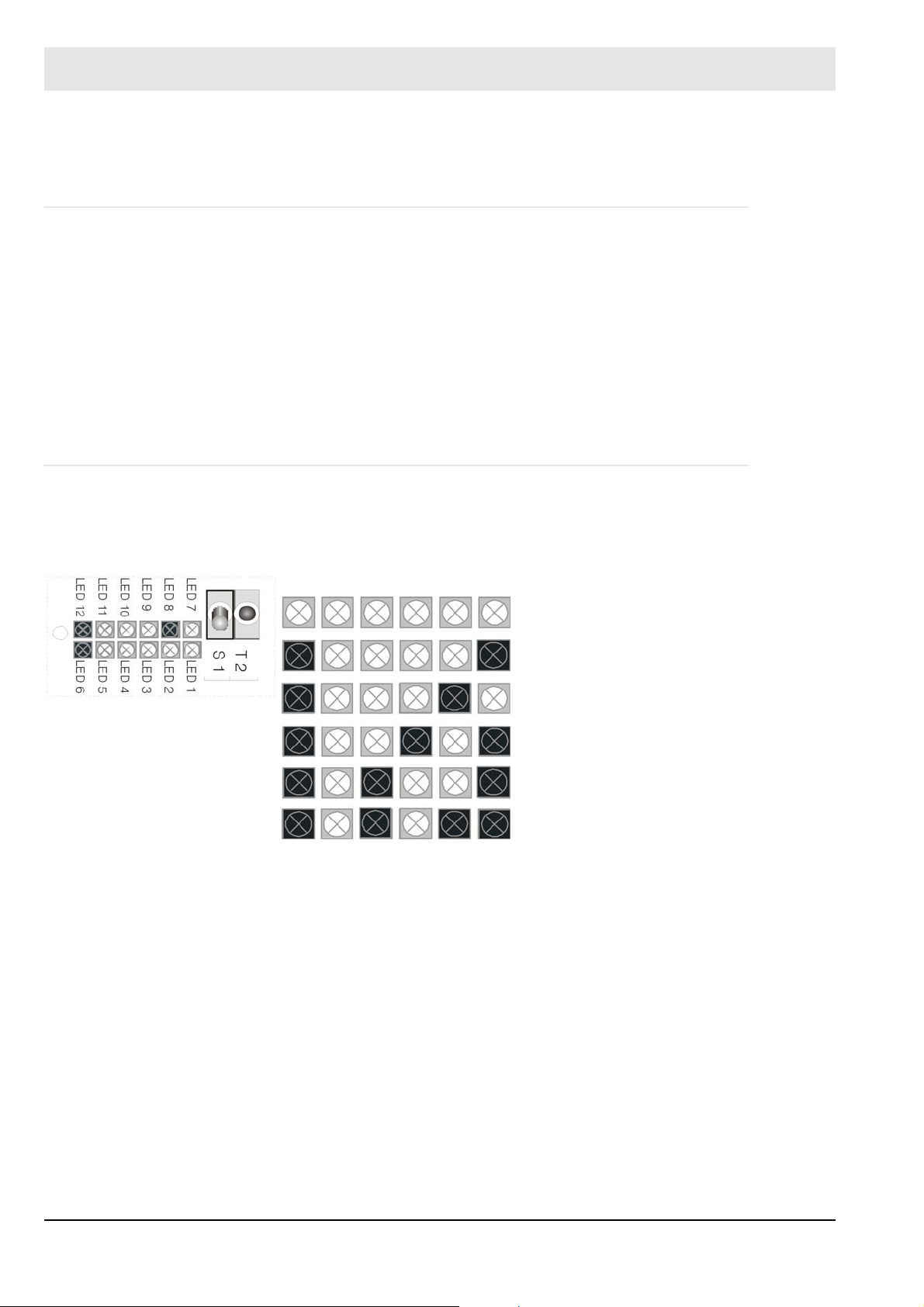
8 Fault Analysis/Trouble-shooting
8 Fault Analysis/Trouble-shooting
8.1 Faults/Warnings
Messages in plain text
See also the [diag] menu overview in chapter 4.4.8 Menu Function 'diag'
Faults/warnings are indicated by:
display and operating unit (Option) in the [diag] menu
Remote Display Software
LAMTEC SYSTEM BUS on external operating unit.
LED row, LED 7 to12on the processor board in the LT2.
If several faults, warnings are present, they can be called in sequence by activating the T2
multifunction key.
8.2 Internal Fault Indication
Indication by LED- row, LED 7 to 12, LED 12 are flashing
Faults are flashing
Fig. 8-1 Display of the active faults
(flashing in red)
12 11 10 9 8 7 Fault
no.
No warning or fault active
1 Probe voltage < -30mV
2 Probe heating is defect
5 Broken wire failure or probe is defect
9 probe dynamic is missing
11 Failure analogue outputs
63
Page 65

8 Fault Analysis/Trouble-shooting
8.3 Warning Indication by LED Line
Indication by LED rows, LED 7 to 12, LED 12 ON = warning
LED 12 11 10 9 8 7 Warning No.:
no warning
1 Internal resistor probe 1 too high
Fig. 8-2 Indication of the
active warnings (red) LED
is ON permanently
2 Offset outside the limits
3 Reference air is missing
4 -P Offset calibration too low, not enough gas
-P Offset calibration too high, filter clogged
5
6 -P Test calibration too low, not enough gas
7 -P Test calibration too, filter clogged
8 Not enough calibration gas
9 Probe’s absolute pressure too high/low
10 Probe temperature too high/low
12 Probe’s temperature sensor defect
64
13 Invalid test gas calibration
14 Test gas calibration not plausible, repeat calibration
19 Analogue input 1: Input value too high/low
20 Analogue input 2: Input value too high/low
21 Analogue input 3: Input value too high/low
22 Analogue input 4: Input value too high/low
23 Error in configuration Analogue outputs
24 Service warning 1
Page 66

8 Fault Analysis/Trouble-shooting
LED 12 11 10 9 8 7 Warning No.:
1
1
1
Only relevant in combination with integrated O2 control.
Without integrated O
8.4 Resetting Faults/Warnings
• by (optional) display and operating unit, in [diag], menu-driven
• by service and diagnostic software in [status], menu-driven
• by digital inputs – input 1
• by pressing the T2 multifunction key (for longer than 3 seconds per fault).
If several faults are present simultaneously, press the multifunction key several times.
Press the key [diag] to switch to warnings and faults. Select the single warnings, faults or limit
values with the cursor keys (up/down).
control the dynamic test has to be switched off parameter 1330 0)
2
25 Service warning 2
26 Probe dynamic is missing
27 Dynamic test is triggered
NOTICE
Limit values are displayed only if they are activated in parameters 930/940/950/960 (access
level ’Service’).
NOTICE
Reset all warnings or faults by quitting them. If necessary eliminate the cause of the warning/
fault.
65
Page 67

8 Fault Analysis/Trouble-shooting
8.5 Faults - Causes and Solutions
8.5.1 Probe voltage too low
• Probe + / - reversed probe connection terminal 33-34 change
• Probe poisoned replace
NOTICE
Probe voltage to air +5 to –30 mV
8.5.2 Probe Heating Defective
NOTICE
In 99 % of all cases, the LS2-K Lambda Probe was disconnected during operation. Reset fault
either by the multifunction key or by the display and operating unit etc.
1. Reset fault either by the multifunction key or by the display and operating unit etc.
2. A defect only exists if the fault cannot be reset.
Possible causes:
• Check fuse F 5 (see chapter 10.7 LT2 Power Electronic Type 657E1882
• Check the probe heater. In an intact heater, ca.10 (9 ... 11 ) can be measured
between terminal 35 and 36. If not (R ) heater faulty. Replace probe.
• If intact, check the supply voltage: The probe heater must be supplied with about 13 VDC,
cyclically reversed. If not, check the wiring and the terminals and tighten if necessary.
NOTICE
The probe is heated with direct current at approx. 13 V, cyclically reversed. Therefore the use
of a multimeter to measure it is somewhat difficult.
NOTICE
The current heating data can be read out from LT2 operating parameters 41/42/43.
8.5.3 Broken Wire Probe/Defective Probe
This message is indicated if the AC internal resistance (Ri) or the ZrO2 cell exceeds the permissible limit of 300 . Before or after this message you normally will get the warning ’Inner
resistance [probe] too high’.
Possible reasons:
• The probe is disconnected (measuring signal on terminals 33 to 34)
• Loose connection check the terminals, re-tighten
• Probe too cold, possibly enhance the heating power gradually (0.5 W)
• Check wiring, if OK replace probe
66
Page 68

8 Fault Analysis/Trouble-shooting
8.5.4 No Probe Dynamics
No probe dynamic detected. Check the probe.
NOTICE
Testing is shut off on delivery.
Activate testing in parameter group 1330 to 1334.
The testing checks, if the measuring value changes more than the parameter set threshold
value during a specified time.
Only valid in combination with an integrated O2 control.
8.5.5 Fault Analogue Output
Check the settings in the parameters of the analogue outputs 1 to 4.
• Parameter 530 … 569 analogue outputs
Check the analogue outputs on the computer electronic and replace if necessary.
Check if an analogue output is activated but is not plugged in (check assembly).
see chapter 10.1 Electrical Connection.
67
Page 69

8 Fault Analysis/Trouble-shooting
8.5.6 O2 Value Is Incorrect
If a control measurement results in a different O2 value than the one displayed:
• Has the relationship between wet/dry measurement been taken into account?
see chapter 10.8 Wet/Dry Measurement Deviations, Conversion Table
• Check LT2 and probe, see chapter 7.2 Checking the Measurement Input of LT2-K
• Commission the new probe as described in chapter 4 Commissioning/Decommissioning
• Measuring value too high? Secondary air, check sealing and hose connections if they are
tight.
NOTICE
During counter measurement, check whether the instrument being used measures wet or dry.
Those with an advance gas cooler are always used for dry measurement. This also applies to
instruments that extract moisture via a chemical compound. The LS2-K Lambda Probe measures wet. The difference between wet and dry measurements can be obtained from the diagram in the Appendix, see chapter 10.8 Wet/Dry Measurement Deviations, Conversion Table
8.5.7 Reference Air Is Missing
Predefine this indication as a fault in parameter P395. If necessary this indication can be defined as a warning in P395 (trigger delay = 1 h).
The amount of reference air which is needed to flow around the reference electrode cannot
be reached. This leads falsifies the measurement value.
Possible causes:
• The reference air connection of the probe is not fed with instrument air (compressed air,
reference air pump).
• The throttle of the reference air is opened insufficiently.
• The difference pressure sensor’s signal has drifted.
Action:
• Check electric and pneumatic connections.
• Readjust the amount of reference air, see chapter 4.7.1.1 Adjust the Amount of the Refer-
ence Air
• Check difference pressure sensor and replace if necessary
• Check pressure input plug-in cards and replace if necessary
68
Page 70

8 Fault Analysis/Trouble-shooting
8.6 Warnings - Causes and Solutions
In general: Warnings do not affect the measurement functions.
8.6.1 LT2-K Calibration Menu
This message is output if the AC internal resistance (RI) of the ZrO2 cell exceeds the permissible limit of 200 during operation.
Possible cause:
Probe aged (worn out) Obtain a spare probe and replace.
Measurement can continue, using caution. Check accuracy by counter-measurement,
see chapter 6 Operation
– Check fuses F2, see chapter10.6 Fuses
– Fault in supply section electronics replace
Check the Lambda Transmitter’s electronic:
Measure the AC voltage across LT2 terminals 33 and 34, using a multimeter.
The result in mV corresponds approx. to half the AC internal resistance.
8.6.2 Offset Voltage out of range
During offset calibration an invalid voltage is detected.
Check if the measuring cell has been supplied with air.
• Check if the flow of compressed air/instrument air is sufficient.
If the rise of pressure is higher than 1 ... 2 mbar, see chapter 7.1.1 Calibrating the Air Volt-
age (Offset)
• Check if pre-filter is torn?
If OK check probe voltage in air.
Permissible range: +5 … -30 mV.
Reversed polarity of the probe terminals 33/34
8.6.3 Reference Air Is Missing (Indication as a Warning in Parameter 395)
Select in parameter 395 sets if the indication should be a fault or a warning (default = failure).
69
Page 71

8 Fault Analysis/Trouble-shooting
8.6.4 Delta-P Offset/Test Gas Calibration is Insufficient - Too less Gas
Insufficient rising of the pressure during offset calibration or test gas calibration at LS2-KV.
Possible causes:
• Instrument air or test gas (1 bar) is missing at the probe.
• The solenoid valve have not been switched.
• The calibration throttle has not opened sufficiently.
Action:
• Check pneumatic connections and throttle settings, see chapter 4.7.1 Measurement with
LS2-K.
• Pre-filter is torn an must be replaced, see chapter 7.4.3 Cleaning/Replacing the Sintered
Metal Pre-filter.
8.6.5 Delta-P Offset or Test Gas Calibration too High - Filter Clogged
The rise of the pressure is too high at LS2-KV during offset calibration or test gas calibration.
Possible causes:
• The pre-pressure of the instrument air or the test gas has been increased (p.ex. from
0.3 bar to 6 bar).
• The throttle is opened too much.
• The pre-filter is clogged
Action:
• Check pre-pressure and throttle adjustment, see chapter 4.7.1 Measurement with LS2-K
• Clean or replace pre-filter, see chapter 7.4.3 Cleaning/Replacing the Sintered Metal Pre-
filter.
8.6.6 Amount of Calibration Gas Insufficient
Insufficient rise of the pressure during offset calibration or test gas calibration of Lambda
Probe
Possible causes:
• The stopcock of probe connection box (PCB) was not opened, see chapter 4.7.1.3 Per-
forming an Offset Calibration with Compressed Air.
• The test gas throttle in the PCB is not open sufficiently.
• The signal from the differential pressure sensor has drifted (recalibrate to ’0’).
• Probe pre-filter cracked or broken (replace)
• see chapter 8.5.4 No Probe Dynamics
70
Page 72

8 Fault Analysis/Trouble-shooting
8.6.7 Test Gas Calibration Is Invalid
The probe temperature which is calculated from the probe voltage and the concentration of
gas is outside a range of 800° - 1200° Kelvin.
Possible causes:
• The connected test gas has not the same O2 concentration as set in parameter 301.
• Sensor aged/contaminated and must be replaced.
• Infiltrated air: Check seals and hose connection if they are tight.
8.6.8 Test Gas Calibration Is Invalid
The O2 value differs more than 0,5 % O2 compared with previous calibration.
Possible causes:
• see chapter 8.6.7 Test Gas Calibration Is Invalid
8.6.9 Analogue Inputs 1/2/3/4 Input Value too Large/too Small
The input value at the relevant analogue input is outside the permissible range.
• Check parameters 574/584/594/604 (minimum) and parameters 578/585/595/605 (maximum). Parameters 570/580/590/600 indicate the current value.
• Check wiring poles reversed?
• Check source (connected instrument).
• Analogue input card defective? Replace it.
8.6.10 Configuration Error at Analogue Outputs
Parameters have been set for analogue outputs not physically found. Check parameters 539,
549, 559, 569 and 530, 540, 550, 560 and compare with the fitted cards.
If necessary, replace the analogue output cards and/or processor card.
8.6.11 Service Warning 1/Service Warning 2
The service warnings are designed to draw attention to regular servicing. The service warnings can be freely defined by the operator, e.g.
Service warning 1 check probe
Service warning 2 replace probe
The appropriate cycle times can be freely configured by the parameters 1260 and 1261.
71
Page 73

9 Spare Parts
9 Spare Parts
All relevant spare parts are listed below.
Recommendation:
(1)
Keep the parts marked with
Keeping parts marked with
Keeping parts marked with
sponding option.
Wear Parts
Description Type no.
1 Repair kit for ZrO2 measurement cell for LS2-K/LS2-KV average
see chapter 7.4.2 Consumables
1 Repair kit for sintered metal pre-filter 650R2065
Spare parts
Description Type no.
1 Installation paste (anti-bonding paste), 5-piece package 650R1090
1 Flange gasket DN65 3 mm Klinger Sil C-4400 657P4209
1 Box containing a range of small accessories for LS2-K/LS2-KV 650R2070
1 Shut-OFF valve 657P0556
1 Absolute pressure sensor with hose 3 mm 650R2066
1 Absolute pressure sensor with hose 4 mm 650R2068
1 Differential pressure sensor with hose 3 mm 650R2067
1 Differential pressure sensor with hose 4 mm 650R2069
1 Solenoid valve (Festo)
1 Solenoid valve incl. solenoid coil 24 V (probes from year of construction 2018)
1 Solenoid coil 24 V (Festo) 657R0401
1 Hose PUN 6x1 black 657P0547
1 Throttle for calibration 657P0525
1 Throttle for reference air 657P0436
1 spare – power electronic 657R1882
1 spare – computer electronic 657R1874
1 spare - display and operating unit 657R0833
1 Reference air pump 657R1062
1 Pump protection filter for reference pump 652R0210
1 LT2 - power supply unit (transformer) 657P0342
1 Analogue output card 0/4 ... 20 mA; 0 ... 10 V (1 channel) 657R0050
1 Analogue output card 0/4 ... 20 mA; 0 ... 10 V floating, maximum potential difference +/- 20 V 657R0051
1 Analogue output card pressure sensor (absolute pressure and differential pressure) 657P0650
1 Analogue output card LT1/LT2 potentiometer 1 ... 5 kΩ 657P6000
1 Analogue output card 0/4 ... 20 mA 663P6001
1 Analogue output card 0/4 ... 20 mA with 24 VDC supply for transmitter 663P6002
1 Analogue output card 0/2 ... 10 V 657P6005
1 Temperature input for Pt100 657R0890
1 Temperature sensor Pt100, 250 mm long 657R0891
1 Relay card for digital outputs with 6 Relay - 1 change over contact each 660R0017
1 Spare fuse box LT2 657R1310
in stock.
(2)
in stock is discretionary.
(3)
in stock only makes sense if system is equipped with the corre-
650R2060...2062
(1)
(1)
(1)
(2)
(2)
(2)
(2)
(2)
(2)
(3)
(3)
(2)
(2)
(3)
(3)
(3)
(3)
(3)
(2)
(2)
(3)
old
old
(2)
(2)
(2)
(2)
(2)
(2)
(2)
(3)
(3)
(2)
(3)
657R0402
657P0862
(1)
72
Page 74

10 Appendix
10 Appendix
10.1 Electrical Connection
Fig. 10-1 Connection diagram LT2
1 Only in type 657R103 via terminals in type 657R102 and 657R104 via plug.
2 The max. current burden for all 4 measurement cards is together: 80 mA
73
Page 75

10 Appendix
10.2 Connection Diagram for LT2-K/LS2-K (semi automatic calibration)
Fig. 10-2 Connection diagram for Gerät/Variable1 semi automatic calibration
74
Page 76

10 Appendix
10.3 Connection Diagram for LT2-KV/LS2-KV (fully automatic calibration)
Fig. 10-3 Fully automatic calibration LT2/LS2-KV
75
Page 77

10 Appendix
10.4 Electrical Connection
Fig. 10-4 Connecting variants LT2
Cable cross section:
Measuring cell heating
terminals 35/36
up to 20 m (65.61 ft)= 1.5 mm2 (AWG 15) 0.75 mm2 (AWG 19)
up to 50 m (164.04 ft)= 2.5 mm2 (AWG 13)
76
other connecting cables
Page 78

10 Appendix
10.5 Jumpers
Fig. 10-5 Schema jumpers
No. Description
1 Modules 1 ... 4 analogue outputs
2 BR10 (N = normal operation) (P = programming mode)
3 Plug for Remote Display Software in combination with RS232 interface module
4 DIP switch
5 Multifunction key
6 BR101 termination resistor for LAMTEC SYSTEM BUS
7 BR 106 and 107 potential allocation for digital outputs
8 Terminal for LAMTEC SYSTEM BUS
9 Terminal for digital inputs
10 Terminal for analogue inputs
11 Maintenance switch
12 Terminal for probes
13 LED line for process and status indications (failure/warning)
14 Terminal for monitor output
15 Modules 1 ... 4, analogue inputs (current, voltage, potentiometer)
77
Page 79

10 Appendix
No. Description
16 Terminal for analogue input
17 Terminal for relay output 1, e.g. for collective fault indicator
18 Terminal for power supply 230/115 V, 50/60 Hz,
19 Transformer connection, 230/115 V switching
(ATTENTION: Exchanging F1 is mandatory)
LAMTEC SYSTEM BUS
BR101:
BR105:
The new processor card must also be set up for the LAMTEC SYSTEM BUS (BR12 and
BR13 in position “C“).
Digital inputs
BR106, 107: Position 1-2:
see chapter 4.2 Monitor Output
Selection of connection resistance: 1-2 off, 2-3 on.
Position 2-3
Digital inputs referenced to instrument potential.
Position 2-3:
Digital inputs, galvanic isolation.
78
Page 80

10 Appendix
10.6 Fuses
Fig. 10-6 Schema of fuses
Designation Value Function
F1 1A inertial for 230 V (IEC60127-2/5)
2A inertial for 115 V (IEC60127-2/5)
F2 0.4 A inertial (IEC60127-2/3 or /5) Probe measuring electronics
F3 1 A inertial (IEC60127-2/3 or /5) 12 V for display background illumination
F4 1.25 A inertial (IEC60127-2/3 or /5) 5 V supply for processor card
F5 4 A inertial
from 11/2016 3,15A ultra slow fuse
F6 0.315 A inertial (IEC60127-2/3 or /5) LAMTEC SYSTEM BUS
NOTICE
Fuse replacement F1/F3 when changeover 230/115 VAC necessary !
Primary fuse
Probe heating and 24 V supply
79
Page 81

10 Appendix
10.7 LT2 Power Electronic Type 657E1882
Fig. 10-7 LT2 Power electronic type 657E1882
1 Transformer LT2 230/115 V change over 10 BR 106, BR 107
2 Module 1-4 Analogue outputs 11 Analogue outputs
3 Plug connector for interface modules, 12 Probe connection
e.g. RS232 in combination with interface module 13 Monitor output
4 DIP-switch 14 Analogue inputs
5 Maintenance switch 15 Relay output 1 e.g. for combined fault indication.
6 Multifunction push button switch 16 Power supply connection 230/115 V, 50/60 Hz
7 Row of LED’s for operating and status messages
(fault/warning)
8 LAMTEC SYSTEM BUS 18 Power supply switch
9 Digital inputs (open collector) 19 Electrical connection X211 for relay module
CAUTION!
Different fuse figures F1 for 230 V and 115 V supply voltage.
Guard against supply voltage toggling!
17 Module 1-4
Analogue inputs (voltage, current, potentiometer)
80
Page 82

10 Appendix
10.8 Wet/Dry Measurement Deviations, Conversion Table
NOTICE
The LT2 carries out measurements directly in the humid flue gases (wet measurement). When
extractive devices are used, flue gases are removed and prepared. "Dry Measurements" are
normally used here, since the humidity has been extracted from the flue gas. As a result, O
measurement values vary (see diagrams below).
2
Theoretical maximum deviations between wet and
dry measurement of the O2 concentration with
natural gas (CH4) or oil (CH2)X as fuel
O2 concentration range Constant K Gas/CH
0 - 6% O
6 - 12% O
0 - 12% O
2
2
2
Alternatively, the H2O share can be automatically calculated via a fixed factor.
81
Calibration diagram and conversion table of the concentration values of wet (O
) and dry (O
2(n)
) measured oxygen
2(tr)
Constant K oil/(CH2)
4
1.18 1.115
1.12 1.08
1.15 1.10
X
Page 83

11 EU Declaration of Conformity
11 EU Declaration of Conformity
82
Page 84

11 EU Declaration of Conformity
83
Page 85

11 EU Declaration of Conformity
84
Page 86

The information in this publication is subject to technical changes.
LAMTEC Meß- und Regeltechnik
für Feuerungen GmbH & Co. KG
Wiesenstraße 6
D-69190 Walldorf
Telefon: +49 (0) 6227 6052-0
Telefax: +49 (0) 6227 6052-57
info@lamtec.de
www.lamtec.de
Printed in Germany | Copyright 2019
Publication no. DLT3023-19-aEN-003
 Loading...