

Page 1

Quick Reference for Endusers
Lambda Transmitter LT3-F
Combination Probe KS1D
Application only in Connection with
BT300/ETAMATIC/FMS/VMS to CO/O
-Control
2
Sensors and Systems for Combustion Technology
www.lamtec.de
Page 2

Page 3

Table of Contents
Table of Contents
1 Important Information about the Manual . . . . . . . . . . . . . . . . . . . . . . . . . . . . . . . . . . . . . . . . 7
1.1 Validity of these Instructions. . . . . . . . . . . . . . . . . . . . . . . . . . . . . . . . . . . . . . . . . . . . . . . 7
1.2 Information on Using this Operating Manual . . . . . . . . . . . . . . . . . . . . . . . . . . . . . . . . . . 8
2 General Safety Instructions . . . . . . . . . . . . . . . . . . . . . . . . . . . . . . . . . . . . . . . . . . . . . . . . . . 9
2.1 Classification of the Safety Instructions and Warnings . . . . . . . . . . . . . . . . . . . . . . . . . . 9
2.2 Proper Use - Conditions of Use . . . . . . . . . . . . . . . . . . . . . . . . . . . . . . . . . . . . . . . . . . . 10
2.3 Permissible Users . . . . . . . . . . . . . . . . . . . . . . . . . . . . . . . . . . . . . . . . . . . . . . . . . . . . . 11
2.4 Safety Equipment/Safety Measures. . . . . . . . . . . . . . . . . . . . . . . . . . . . . . . . . . . . . . . . 12
3 Product Description. . . . . . . . . . . . . . . . . . . . . . . . . . . . . . . . . . . . . . . . . . . . . . . . . . . . . . . . 14
3.1 Applications . . . . . . . . . . . . . . . . . . . . . . . . . . . . . . . . . . . . . . . . . . . . . . . . . . . . . . . . . . 14
3.2 Declaration of Conformity . . . . . . . . . . . . . . . . . . . . . . . . . . . . . . . . . . . . . . . . . . . . . . . 15
4 Mounting and Functions . . . . . . . . . . . . . . . . . . . . . . . . . . . . . . . . . . . . . . . . . . . . . . . . . . . . 17
4.1 Designs and Accessories of the KS1D Combination Probe. . . . . . . . . . . . . . . . . . . . . . 17
4.2 Connection Extension . . . . . . . . . . . . . . . . . . . . . . . . . . . . . . . . . . . . . . . . . . . . . . . . . . 18
5 Display and Operational Controls . . . . . . . . . . . . . . . . . . . . . . . . . . . . . . . . . . . . . . . . . . . . 19
5.1 Operation . . . . . . . . . . . . . . . . . . . . . . . . . . . . . . . . . . . . . . . . . . . . . . . . . . . . . . . . . . . . 20
5.2 Menu Structure . . . . . . . . . . . . . . . . . . . . . . . . . . . . . . . . . . . . . . . . . . . . . . . . . . . . . . . 20
5.2.1 Password Entry Menu Structure . . . . . . . . . . . . . . . . . . . . . . . . . . . . . . . . . . . . 20
5.2.2 Information Menu Structure . . . . . . . . . . . . . . . . . . . . . . . . . . . . . . . . . . . . . . . . 21
5.2.3 Calibration Menu Structure . . . . . . . . . . . . . . . . . . . . . . . . . . . . . . . . . . . . . . . . 21
5.2.4 Settings Menu Structure . . . . . . . . . . . . . . . . . . . . . . . . . . . . . . . . . . . . . . . . . . 22
5.3 Status Line . . . . . . . . . . . . . . . . . . . . . . . . . . . . . . . . . . . . . . . . . . . . . . . . . . . . . . . . . . . 23
5.4 Main Menu . . . . . . . . . . . . . . . . . . . . . . . . . . . . . . . . . . . . . . . . . . . . . . . . . . . . . . . . . . . 24
5.4.1 Main Menu - Password Entry. . . . . . . . . . . . . . . . . . . . . . . . . . . . . . . . . . . . . . . 25
5.4.2 Main Menu - Information . . . . . . . . . . . . . . . . . . . . . . . . . . . . . . . . . . . . . . . . . . 26
5.4.3 Main Menu - Calibration. . . . . . . . . . . . . . . . . . . . . . . . . . . . . . . . . . . . . . . . . . . 27
5.4.4 Main Menu - Settings. . . . . . . . . . . . . . . . . . . . . . . . . . . . . . . . . . . . . . . . . . . . . 28
6 Commissioning . . . . . . . . . . . . . . . . . . . . . . . . . . . . . . . . . . . . . . . . . . . . . . . . . . . . . . . . . . . 30
6.1 Operating Conditions . . . . . . . . . . . . . . . . . . . . . . . . . . . . . . . . . . . . . . . . . . . . . . . . . . . 30
6.2 Installation . . . . . . . . . . . . . . . . . . . . . . . . . . . . . . . . . . . . . . . . . . . . . . . . . . . . . . . . . . . 32
6.3 Measurement Start-up . . . . . . . . . . . . . . . . . . . . . . . . . . . . . . . . . . . . . . . . . . . . . . . . . . 32
6.3.1 Enter the Password for the Access Level . . . . . . . . . . . . . . . . . . . . . . . . . . . . . 33
6.3.2 Activate/deactivate Maintenance Mode . . . . . . . . . . . . . . . . . . . . . . . . . . . . . . . 34
6.3.3 Response of the Internal Resistance Regulation. . . . . . . . . . . . . . . . . . . . . . . . 36
6.3.4 Premature Cold Start Termination . . . . . . . . . . . . . . . . . . . . . . . . . . . . . . . . . . . 37
6.3.5 Reading the Measured Values. . . . . . . . . . . . . . . . . . . . . . . . . . . . . . . . . . . . . . 38
6.4 Calibrating the Probe . . . . . . . . . . . . . . . . . . . . . . . . . . . . . . . . . . . . . . . . . . . . . . . . . . . 39
6.4.1 Offset Calibration . . . . . . . . . . . . . . . . . . . . . . . . . . . . . . . . . . . . . . . . . . . . . . . . 41
6.4.2 Calibrating the O
Electrode . . . . . . . . . . . . . . . . . . . . . . . . . . . . . . . . . . . . . . . 43
2
6.4.3 Perform a Calibration of the CO/H2 Electrode . . . . . . . . . . . . . . . . . . . . . . . . . . 44
6.5 Settings . . . . . . . . . . . . . . . . . . . . . . . . . . . . . . . . . . . . . . . . . . . . . . . . . . . . . . . . . . . . . 46
6.5.1 Maintenance Mode . . . . . . . . . . . . . . . . . . . . . . . . . . . . . . . . . . . . . . . . . . . . . . 46
6.5.2 Filter Time . . . . . . . . . . . . . . . . . . . . . . . . . . . . . . . . . . . . . . . . . . . . . . . . . . . . . 46
6.5.3 Analogue Outputs . . . . . . . . . . . . . . . . . . . . . . . . . . . . . . . . . . . . . . . . . . . . . . . 47
6.5.4 Replacing a Probe . . . . . . . . . . . . . . . . . . . . . . . . . . . . . . . . . . . . . . . . . . . . . . . 47
2
Page 4

Table of Contents
6.5.5 Display . . . . . . . . . . . . . . . . . . . . . . . . . . . . . . . . . . . . . . . . . . . . . . . . . . . . . . . . 47
6.5.6 Limit Values . . . . . . . . . . . . . . . . . . . . . . . . . . . . . . . . . . . . . . . . . . . . . . . . . . . . 47
6.6 Test Certificate . . . . . . . . . . . . . . . . . . . . . . . . . . . . . . . . . . . . . . . . . . . . . . . . . . . . . . . . 49
6.7 Probe Certificate . . . . . . . . . . . . . . . . . . . . . . . . . . . . . . . . . . . . . . . . . . . . . . . . . . . . . . 50
7 Maintenance . . . . . . . . . . . . . . . . . . . . . . . . . . . . . . . . . . . . . . . . . . . . . . . . . . . . . . . . . . . . . . 51
7.1 Checking/Calibrating the KS1D Combination Probe . . . . . . . . . . . . . . . . . . . . . . . . . . . 51
7.1.1 Checking/Calibrating the Air Voltage (Offset) . . . . . . . . . . . . . . . . . . . . . . . . . . 51
7.1.2 Checking/Calibrating the O2 Electrode . . . . . . . . . . . . . . . . . . . . . . . . . . . . . . . 51
7.1.3 Checking/Calibrating the CO/H2 Electrode . . . . . . . . . . . . . . . . . . . . . . . . . . . . 51
7.1.4 Checking/Calibrating with Test Gas. . . . . . . . . . . . . . . . . . . . . . . . . . . . . . . . . . 52
7.1.5 Checking/Calibrating with Reference Measurement . . . . . . . . . . . . . . . . . . . . . 56
7.1.6 Simple Function Test of the CO/H2 Electrode . . . . . . . . . . . . . . . . . . . . . . . . . . 56
7.1.7 Wear-and-Tear Parts of the KS1D Combination Probe . . . . . . . . . . . . . . . . . . . 56
7.2 Replacing a Probe . . . . . . . . . . . . . . . . . . . . . . . . . . . . . . . . . . . . . . . . . . . . . . . . . . . . . 57
7.3 Sensor Replacement KS1D-HT . . . . . . . . . . . . . . . . . . . . . . . . . . . . . . . . . . . . . . . . . . . 59
8 Correcting Faults . . . . . . . . . . . . . . . . . . . . . . . . . . . . . . . . . . . . . . . . . . . . . . . . . . . . . . . . . . 62
8.1 Faults and Warnings . . . . . . . . . . . . . . . . . . . . . . . . . . . . . . . . . . . . . . . . . . . . . . . . . . . 62
8.1.1 Faults . . . . . . . . . . . . . . . . . . . . . . . . . . . . . . . . . . . . . . . . . . . . . . . . . . . . . . . . . 63
8.1.2 Warnings . . . . . . . . . . . . . . . . . . . . . . . . . . . . . . . . . . . . . . . . . . . . . . . . . . . . . . 68
8.1.3 Call of the Fault History . . . . . . . . . . . . . . . . . . . . . . . . . . . . . . . . . . . . . . . . . . . 70
9 Decommissioning . . . . . . . . . . . . . . . . . . . . . . . . . . . . . . . . . . . . . . . . . . . . . . . . . . . . . . . . . 71
9.1 Decommissioning. . . . . . . . . . . . . . . . . . . . . . . . . . . . . . . . . . . . . . . . . . . . . . . . . . . . . . 71
9.1.1 Protection Against Emissions from Gas Carrying Channels . . . . . . . . . . . . . . . 71
10 Options . . . . . . . . . . . . . . . . . . . . . . . . . . . . . . . . . . . . . . . . . . . . . . . . . . . . . . . . . . . . . . . . . . 72
10.1 Analogue Outputs via LSB Module Current, alternative Voltage, LSB address 19 . . . . 72
10.1.1 Functional Description . . . . . . . . . . . . . . . . . . . . . . . . . . . . . . . . . . . . . . . . . . . . 72
10.1.2 Factory Setting of Analogue Outputs via LSB Module. . . . . . . . . . . . . . . . . . . . 73
10.1.3 Conversion of the Output Range via the User Interface . . . . . . . . . . . . . . . . . . 74
10.2 Digital Outputs via LSB Module, LSB Address 03 and 51 . . . . . . . . . . . . . . . . . . . . . . . 75
10.2.1 Functional Description . . . . . . . . . . . . . . . . . . . . . . . . . . . . . . . . . . . . . . . . . . . . 75
10.2.2 Factory Setting of the Digital Outputs . . . . . . . . . . . . . . . . . . . . . . . . . . . . . . . . 76
10.2.3 Diagnosis of the Digital Outputs . . . . . . . . . . . . . . . . . . . . . . . . . . . . . . . . . . . . 77
10.3 Digital Inputs via the LSB Module, LSB Address 11 and 55. . . . . . . . . . . . . . . . . . . . . . 78
10.3.1 Functional Description . . . . . . . . . . . . . . . . . . . . . . . . . . . . . . . . . . . . . . . . . . . . 78
10.3.2 Factory Settings of the Digital Inputs . . . . . . . . . . . . . . . . . . . . . . . . . . . . . . . . . 79
10.3.3 Diagnosis of the Digital Inputs . . . . . . . . . . . . . . . . . . . . . . . . . . . . . . . . . . . . . . 79
10.4 LSB Module for Calculating Combustion Efficiency. . . . . . . . . . . . . . . . . . . . . . . . . . . . 80
10.4.1 Functional Description . . . . . . . . . . . . . . . . . . . . . . . . . . . . . . . . . . . . . . . . . . . . 80
10.5 External Connection. . . . . . . . . . . . . . . . . . . . . . . . . . . . . . . . . . . . . . . . . . . . . . . . . . . . 82
10.5.1 Commissioning of the Additional Modules . . . . . . . . . . . . . . . . . . . . . . . . . . . . . 84
11 Storage . . . . . . . . . . . . . . . . . . . . . . . . . . . . . . . . . . . . . . . . . . . . . . . . . . . . . . . . . . . . . . . . . . 85
11.1 Storage Conditions . . . . . . . . . . . . . . . . . . . . . . . . . . . . . . . . . . . . . . . . . . . . . . . . . . . . 85
12 Disposal Notes . . . . . . . . . . . . . . . . . . . . . . . . . . . . . . . . . . . . . . . . . . . . . . . . . . . . . . . . . . . . 86
12.1 Environmental Protection, Waste Disposal . . . . . . . . . . . . . . . . . . . . . . . . . . . . . . . . . . 86
13 Appendix. . . . . . . . . . . . . . . . . . . . . . . . . . . . . . . . . . . . . . . . . . . . . . . . . . . . . . . . . . . . . . . . . 87
3
Page 5

Table of Contents
13.1 LT3-F spare parts. . . . . . . . . . . . . . . . . . . . . . . . . . . . . . . . . . . . . . . . . . . . . . . . . . . . . . 87
13.2 Spare Parts Combination Probe KS1D in Housing . . . . . . . . . . . . . . . . . . . . . . . . . . . . 87
13.3 Spare Parts Combination Probe KS1D without Housing . . . . . . . . . . . . . . . . . . . . . . . . 87
13.4 Spare Parts KS1D-HT Combination Probe . . . . . . . . . . . . . . . . . . . . . . . . . . . . . . . . . . 88
13.5 Wet/Dry Measurement Deviations, Conversion Table . . . . . . . . . . . . . . . . . . . . . . . . . . 89
4
Page 6

1 Important Information about the Manual
1 Important Information about the Manual
1.1 Validity of these Instructions
This manual describe the Lambda Transmitter LT3-F with all required components. The information in this document applies to the software version 1.0.0.0. If you utilise a different version, this can lead to other effects to your device than those described in this manual.
The CO/O2 control described in this document must be activated in the burner control units
stated above and the required measurement equipment must be connected.
The basic documentation to this commissioning supplement is:
• Manual of BurnerTronic BT300, BT320 ... BT340 (publication no. DLT1201)
• Manual of Lambda Transmitter LT3-F KS1D (publication no. DLT3140)
The lambda transmitter LT3-F must be operated with the CO/O2 control option.
For this purpose, the following LAMTEC burner control systems can be used:
• BT300
• ETAMATIC/ETAMATIC S
• ETAMATIC OEM/ETAMATIC S OEM
• ETAMATIC V/ETAMATIC VS
• FMS
• VMS
The description of the CO/O2 control can be found in the following documents:
• Commissioning supplement for the CO/O2 control in connection with BT300 (publication
no. DLT1209)
• Commissioning supplement for the CO/O2 control in connection with FMS/VMS/ETAMATIC (publication no. DLT5015)
NOTICE
The current publications are available for download from the LAMTEC Website,
www.lamtec.de.
5
Page 7

1 Important Information about the Manual
1.2 Information on Using this Operating Manual
NOTICE
Before starting work, you absolutely must read these instructions!
Carefully observe all warning notes!
They contain important data and information, the compliance with which will ensure the function of the device and, in turn, reliable measurement results.
The device described here corresponds with the standard configuration.
Particular attention must be paid to information and warnings. These are indicated by re-
spective pictograms. They serve to safeguard your personal safety and help you to avoid operating errors.
This operating manual contains the information required for the product to be used in a manner that is compliant with its intended use. It is intended for technically qualified personnel who
are appropriately trained and who possess the relevant knowledge in the area of measurement, control and steering technology.
This operating manual is an inherent part of the delivery. For reasons of clarity, it is not possible to cover all possible designs of the described system. Please contact us if you wish to set
up, operate, or maintain the device differently from the instructions given here.
6
Page 8

2 General Safety Instructions
2 General Safety Instructions
2.1 Classification of the Safety Instructions and Warnings
The following symbols are used in this document to draw the user's attention to important safety information. They are located at points where the information is required. It is essential that
the safety information is observed and followed, and that applies, in particular, to the warnings.
DANGER!
This draws the user's attention to imminent danger. If it is not avoided, it will result in death or
very serious injury. The plant or something in its surroundings could be damaged.
WARNING!
This draws the user's attention to the possibility of imminent danger. If it is not avoided, it may
result in death or very serious injury. The plant or something in its surroundings could be damaged.
CAUTION!
This draws the user's attention to the possibility of imminent danger. If it is not avoided, it may
result in minor injuries. The plant or something in its surroundings could be damaged.
NOTICE
This draws the user's attention to important additional information about the system or system
components and offers further tips.
The safety information described above is incorporated into the instructions.
In this connection, the operator is requested to:
1 Comply with the accident prevention regulations whenever work is being carried out.
2 Do everything possible in the circumstances to prevent personal injury and damage to
property.
7
Page 9

2 General Safety Instructions
2.2 Proper Use - Conditions of Use
Operation
The LT3-F lambda transmitter is an electronic data interpreting device which is used in conjunction with the KS1D combination probe for the continuous measurement of the O2 concentration and the oxidising components (CO/H2) in non-combustible gases in the
superstoichiometric area.
Prerequisites
It is assumed that plant planning, mounting, installation, commissioning, maintenance, and
service work will be carried out by sufficiently trained personnel and that this work will be
checked by responsible skilled personnel. It must be particularly noted that
• the operation complies with the technical data and specifications regarding permissible
use, mounting, connection, and environment and operating conditions (refer to the contract documents, the device user information, rating plates, etc.).
• work will be carried out in accordance with the local, plant-specific circumstances and with
regard to the operational risks and directives.
• all the measures required to preserve the value, e.g. for transportation and storage as well
as maintenance and service, are maintained.
Intended use
The product described here has left the factory in a flawless, safe and checked condition and
it must be maintained exclusively in the manner that is described by the manufacturer. Equally,
the proper transportation, correct storage and setup as well as the careful operation and maintenance, are critical for the flawless and safe operation of the device. Sufficiently qualified personnel must be used to install and operate this product. They must be familiar with the security
advice and warnings specified here and ensure they can be implemented flawlessly. Unqualified persons working on the device or the warning information provided here or on the device
not being observed could result in serious personal injury and / or damage to property. The
device is being used as intended if the device is being used solely for the application specified
in the technical description. Auxiliary devices or those from other manufacturers must be recommended or authorised by LAMTEC. Provided the safety information and operating directives specified in this manual are observed, this device should not present any risks in terms
of damage to property or the health of personnel.
8
Page 10

2 General Safety Instructions
2.3 Permissible Users
Qualified personnel
The person responsible for safety absolutely must guarantee that
• only qualified personnel perform work on the system parts.
Due to their training, education, experience, or instruction and due to their knowledge of
pertinent standards, provisions, accident prevention regulations, and system conditions,
qualified personnel are authorized to perform these tasks by the person responsible for
the safety of people and the system. It is decisive that this personnel must be able to recognise and prevent risks on time.
Experts are considered to be people according to DIN VDE 0105 or IEC 364 or directly
comparable standards like DIN 0832.
• These persons must have access to the provided operating manual and any pertinent order-related documentation during all work and observe these documents within the scope
of preventing risks and damage.
User groups
For the handling of the lambda transmitter LT3-F, three user groups are required:
• Service technicians of LAMTEC or its OEM customers and/or trained customer personnel:
– Qualified technicians/engineers have very good knowledge of the device.
– SERVICE access level - password-protected
• Operators, customer fitters, technicians for instrumentation and control technology, electricians, and electronic engineers have introductory knowledge of the device.
– CUSTOMER access level - password-protected
• Operating personnel with basic knowledge
– OPERATION access level - no password
9
Page 11

2 General Safety Instructions
2.4 Safety Equipment/Safety Measures
Hazards from electrical equipment
The Lambda Transmitter LT3-F combination probe is equipment for use in industrial electrical
power installations. Always switch off the power when working on mains connections or mains
voltage. If contact protection has been removed, reattach it before switching on the power supply again. Damage to health or equipment may result from improper use or improper handling.
NOTICE
To avoid damage, always observe the respective security notices.
Preventive measures for improving operating safety
If the LT3-F is used in conjunction with control and steering technology, the operator must ensure that any breakdown or failure of the LT3-F device does not cause inadmissible damage
or dangerous operating states. To avoid faults which could cause direct or indirect personal
or material damage, the operator must ensure that:
• the responsible maintenance personnel can be reached at any time and as quickly as possible
• the maintenance personnel are trained to correctly respond to faults with the Lambda
Transmitter LT3-F and the associated malfunctions
• in the case of doubt, the faulty equipment can be switched off immediately
• A switch-off does not lead to direct follow-up problems.
Avoiding consequential damages
To avoid consequential damages in the event of failure, which could cause direct or indirect
personal or material damage, the owner must ensure that qualified personnel can assess the
faults and initiate appropriate measures to tackle them.
Protect against gas leakage from the gas-bearing channel
The combination probe KS1D is fitted directly to the gas-bearing channel via the probe installation fitting (PIF). If the combination probe KS1D or the probe installation fitting (PIF) are dismantled, depending on the plant but particularly in the case of excess pressure, aggressive
and / or hot gas can seep out of the channel and this could pose a serious health hazard to
an unprotected operator if suitable safety measures have not be taken previously. For prevention, suitable protective measures must be taken in advance.
WARNING!
In the case of excess pressure and temperatures in excess of 200 °C in the gas channel, gases could escape when dismantling the combination probeKS1D or the probe installation fitting
(PIF).
Always switch off the plant prior to opening. If this is not possible, wear protective clothing
and a mask.
Fix respective warning information in close proximity to the mounting site.
Immediately seal the opening again.
WARNING!
Danger from electrical shock
The device contains live parts and touching these parts could cause electric shock.
Before opening the housing, disconnect the mains plug!
10
Page 12

2 General Safety Instructions
Decommissioning/recommissioning
The LT3-F Lambda Transmitter and the KS1D combination probe are a high-quality,
electronic measuring system. It therefore requires careful handling in all situations - decommissioning, transport, and storage.
NOTICE
Do not switch off the LT3-F Lambda Transmitter as long as the KS1D combination probe is
mounted. Not even if the associated plant has been brought to a standstill. Residual gases will
cause corrosion and could damage the probe.
Do not store the device outside without any protection!
Always store in a dry location and, if possible, keep in the original packaging.
When uninstalling, protect the ends of cables and the connectors from corrosion and soil-
ing. Corroded connectors can cause malfunctions.
If possible, always transport in the original packaging.
11
Page 13

3 Product Description
3 Product Description
3.1 Applications
The LT3-F lambda transmitter has been developed to use in conjunction with the KS1D combination probe for the simultaneous measurement of the O2 concentration and oxidising components (CO/H2), displayed as CO equivalents (COe), usually in the flue gases from
combustion systems in the superstoichiometric area (>1).
Application only in connection with CO/O2 control. The fail-safe function is only valid for the
hole system, not for single components.
12
Page 14

3 Product Description
3.2 Declaration of Conformity
13
Page 15

3 Product Description
14
Page 16

4 Mounting and Functions
4 Mounting and Functions
4.1 Designs and Accessories of the KS1D Combination Probe
The KS1D combination probe permits a simultaneous measurement
of the O2 concentration and combustible, oxidising gas components (CO/H2) displayed as
CO equivalent (COe), in the flue gases from combustion systems in the superstoichiometric area
(>1) in situ (directly in the flue gas).
Fig. 4-1 Standard design of the KS1D combination probe
1 KS1D combination probe in standard housing
Standard cable length 2 m, PTFE, with connecting plug
2 Probe installation fitting (PIF)
3 Measuring gas extraction device (GED)
Fig. 4-2 KS1D combination probe without housing
Alternatively:
Fig. 4-3 KS1D combination probe in HT design
1 KS1D combination probe in high-temperature housing
Standard cable length 2 m, PTFE, with connecting plug
2 Flue gas bypass tube
15
Page 17

4 Mounting and Functions
4.2 Connection Extension
Extension via probe terminal box
In preparation.
Extension via extension cable
For distances > 2 m, extension cables in lengths of 2 m and 5 m are available.
NOTICE
The maximum distance between LT3-F and combination probe KS1D may not exceed 10 m.
With longer distances the approval of the system for continuous operation expires.
For distances longer than 10 m the risk of EMC increases.
LAMTEC assumes no responsibility for correct, error-free functions.
16
Page 18

5 Display and Operational Controls
5 Display and Operational Controls
To display and operate LT3-F, the user interface is integrated into the front door of LT3-F (included in the standard scope of supply).
Functions:
• Reading of the O
• Password entry
• Information regarding the probe, fuel, warnings, faults, software version,
CRC, and serial number
• Calibration of measurement
• Settings maintenance, filter time, analogue output, probe replacement, display,
limit values, and digital outputs
and COe measured values
2
Fig. 5-1 LT3-F user interface
Fig. 5-2 Housing with user interface
17
Page 19

5 Display and Operational Controls
5.1 Operation
Using the arrow keys you can navigate within the menus.
In the process, move the keys and to the right or left by one to make a selection.
ENTER ENTER takes you to menu entries or to the edit mode in the case of selected pa-
rameters or values.
With the keys and the currently selected value can be changed accordingly Hold
down the respective key and the value will count automatically up or down.
BACK BACK leaves the window, menu, or edit mode.
5.2 Menu Structure
5.2.1 Password Entry Menu Structure
Without access level
Customer access level
Service access level
18
Page 20

5 Display and Operational Controls
5.2.2 Information Menu Structure
5.2.3 Calibration Menu Structure
19
Page 21

5 Display and Operational Controls
5.2.4 Settings Menu Structure
20
Page 22

5 Display and Operational Controls
5.3 Status Line
The status line contains information about LT3-F, including the device family.
Description status line:
Active fault/warning
Operating mode OK
Heat-up (cold start)
Status of limit values 1-4
Active limit value not triggered
Non-active limit value (off)
Active limit value undershot/exceeded
Active maintenance mode
Without access level
Access level 1 - Customer
Access level 2 - Service
Window number
21
Page 23

5 Display and Operational Controls
5.4 Main Menu
Main display Main menu
The following values are displayed:
•O
value, resolution 0.1%
2
•COe value (recommended 1,000 ppm), resolution 1 ppm
•COe: Probe signal dynamics
• CO edge signal reached/exceeded
The factory-set reaction threshold lies at 40%. The display shows whether the reaction thresh-
old is reached. When the reaction threshold is reached, the CO edge signal is present and the
CO control becomes active. This is shown through a symbol in the display or can be read
via the LSB remote software in Parameter 444. The desired response threshold be set on the
display or using Parameter 453 of the LSB remote software. Access level 2 is required for service!
Press ENTER to access the main menu.
Meaning of the symbols:
Password entry
Information regarding the probe and fuel, warnings and faults,
software version, CRC, and serial number
Calibration of measurement
Settings (maintenance, filter time, analogue output, probe replacement, display,
limit values and digital outputs)
22
Page 24
5 Display and Operational Controls
5.4.1 Main Menu - Password Entry
23
Page 25

5 Display and Operational Controls
5.4.2 Main Menu - Information
Meaning of the symbols:
Measured values and probe data
Fault/warning history
Software version of LT3-F and display
CRC checksums
Serial number
Manual reset of the limit values if they are set to manual reset
24
Page 26

5 Display and Operational Controls
5.4.3 Main Menu - Calibration
Meaning of the symbols: Required access level
Offset of calibration to 21% O2 (air calibra-
tion)
COe calibration At least 1 (Customer) or higher
O2 calibration At least 1 (Customer) or higher
Fuel changeover At least 1 (Customer) or higher
Without
25
Page 27

5 Display and Operational Controls
5.4.4 Main Menu - Settings
Meaning of the symbols: Required access level
Maintenance mode Without
Filter time of the measured values Without
Analogue outputs At least 1 (Customer) or higher
Triggering of probe replacement At least 1 (Customer) or higher
COe trigger threshold At least 2 (Service)
Display parameters Without
Digital outputs At least 2 (Service)
Limit values At least 1 (Customer) or higher
26
Page 28

6 Commissioning
6 Commissioning
WARNING!
Prior to commissioning, carefully read the manual and heed the instructions.
The measuring system may be operated only by trained and instructed personnel!
Improper working/operation can cause death, serious bodily injury and/or considerable mate-
rial damage.
NOTICE
Before commissioning, the KS1D combination probe and all alarm/signal outputs are connected, as described in Chapter 6.2 Installation in these operating instructions, to the LT3-F Lambda Transmitter.
WARNING!
Before actuating the main switch for the voltage supply, ensure all housings (evaluation electronics and terminal boxes, electrical connection of the probe) are sealed in
accordance with the instructions!
27
Page 29

6 Commissioning
6.1 Operating Conditions
NOTICE
If the LT3 is being used for O2 control or the LT3-F for CO/O2 control, it may happen, that the
connected LSB-modules are not be controlled correctly. The LSB modules start to flash red
and the output values are disturbed.
To avoid this, the ETAMATIC or when FMS/VMS then the connected communications processor board/fieldbus module requires a software update to the latest version.
Please check the version before commissioning.
Shown on the ETAMATIC: Using PC software for remote control view version
„Software Version Communication Processor’“
Software-EPROM on processor board in ETAMATIC
Shown on the FMS/VMS:
or
Using PC software for remote control view version
Function up from software version for communication processor for LSB:
When ETAMATIC / ETAMATIC OEM: B9w001, up from April 2015
When communication processor / PROFIBUS connection
for FMS/VMS
When MODBUS connection RTU for FMS/VMS: M9xxx, up from April 2015
When MODBUS connection TCP for FMS/VMS: E9xxx, up from June 2011
If you have any questions, please contact support@lamtec.de or phone +49 6227 605233.
Check on the label ‘Software’ printed on the outside of the
housing of communications processor board / fieldbus module
"Software Version Secondary Communication Processor“
Software-EPROM in communications processor board/fieldbus
A9xxx, up from November
2011
28
Page 30

6 Commissioning
6.2 Installation
Danger of falling!
The mounted probe may not be used as a step. The maximum permissible bending moment
lies at 100 kg. In case of non-observance, the probe can be destroyed.
A fall can result in severe injury or death.
Do not step on the probe! Use appropriate work equipment.
NOTICE
Do not pull on cables or pneumatic connections. The maximum permissible tensile force lies
at 10 kg.
NOTICE
The maximum distance between LT3-F and combination probe KS1D may not exceed 10 m.
With longer distances the approval of the system for continuous operation expires.
For distances longer than 10 m the risk of EMC increases.
LAMTEC assumes no responsibility for correct, error-free functions.
WARNING!
6.3 Measurement Start-up
NOTICE
If it is not possible to switch off the system, the probe can be installed only after a successful
offset calibration and the GED has been aligned.
Commissioning the probe
1. Connect the probe electrically.
2. Switch on the voltage.
3. Enter the password for access level 2 (Service); see Chapter 6.3.1 Enter the Password for
the Access Level.
4. Activate maintenance mode; see Chapter 6.3.2 Activate/deactivate Maintenance Mode.
5. Heat up the probe (10 min. cold start and 30 min. faultless measurement operation)
6. Cold start is displayed.
7. The device automatically changes over to measurement operation.
8. The probe voltages stabilised to (-20 ... + 10mV).
9. The internal resistance stabilised to 15 ... 25 W
10. Calibrate the probe; see Chapter 6.4 Calibrating the Probe.
29
Page 31

6 Commissioning
6.3.1 Enter the Password for the Access Level
In the main menu PASSWORD ENTRY
select
Enter password via and
ENTER .
Access level 1:
Factory setting:
Access level 2: Service level
Customer Level
0000 – access to customer functions only
Customers can change the password for access level 1. For details ask
the burner manufacturer/supplier
Password: customer specific
Access to customer and service functions
30
Page 32

6 Commissioning
6.3.2 Activate/deactivate Maintenance Mode
In maintenance mode, the majority of test routines are disabled. It is advantageous to activate
the maintenance mode during probe calibration. Substitute values can be given as an output
during active maintenance mode.
In the main SETTINGS menu, select
In the MAINTENANCE MODE settings,
select
Menu 460 ACTIVATE/DEACTIVATE MAINTENANCE MODE is opened.
Select with the key and ENTER to
activate/deactivate the maintenance mode.
Activate maintenance mode
Deactivate maintenance mode
If both parameters (LT3 and UI300) are equal
confirm the procedure with ENTER
31
Page 33

6 Commissioning
• The symbol appears in the status line.
• The probe heats up (approx.10 min.).
• LD 603 green OPERATION lights up.
• COLD START is displayed.
The cold start serves to suppress incorrect measured values while the probe is heating
up. A cold start delay is always activated after MAINS ON and a fault reset. Premature
termination via the CALIBRATION menu possible (see Chapter 6.3.4 Premature Cold
Start Termination).
• After a concluded COLD START (approx. 10 minutes), the device switches to measuring
mode.
• The probe voltages U-O2 and U-COe stabilise to values between +10 ... -20 mV.
• The internal resistances of the sensor Rki O2 and Rki CO stabilise to values between
15 ... 25 .
For the analogue outputs, a replacement value can be set via the LSB remote software while
the maintenance mode is active.
Parameter 2035 and Parameter 2042 for analogue output 1
Parameter 2075 and Parameter 2082 for analogue output 2
Wait for transmission end indication.
Return to the SETTINGS menu with the
BACK and repeat the procedure.
In case of cancelling or timeout, this display
appears. Return to the SETTINGS menu
with the BACK .
WARNING!
Danger of burns!
Probe becomes hot during operation.
If the probe is operated when removed, there is a danger of burns on the probe housing.
Never lay the probe on flammable material and heat it up.
Wear protective gloves
32
Page 34

6 Commissioning
6.3.3 Response of the Internal Resistance Regulation
The internal ceramic resistance between the reference and O2 electrodes (Rki O2) is a function of the sensor temperature, which is constantly regulated for a perfect function
of the probe.
NOTICE
The optimum operating point of the KS1D probe lies at a Rki O2 of about 20
This value must be reached before the first offset calibration or after a probe replacement is
triggered.
If the measured R
(see Menu 213), the installation situation of the probe must be changed for optimum operation:
Rki O2 > 25
• The probe does not become hot enough:
– The probe was installed in a cold spot and is thus cooled.
Determine a new installation site.
– If necessary, check whether aRki O2 of 20 is reached when it is disassembled.
If a too high Rki O2 is assumed by the internal resistance regulation, the probe functions outside of its optimum operating point.
Rki O2 < 20
• The internal resistance regulation automatically sets the Rki setpoint value to 20:
- After 30 minutes in fault-free measurement operation and subsequent offset
calibration
- After 120 minutes in fault-free measurement operation without an offset calibration
deviates too strongly from the optimum setpoint value Rki S = 20
ki O2
33
Page 35

6 Commissioning
6.3.4 Premature Cold Start Termination
Occasionally, it might be necessary to terminate the COLD START prematurely, e.g., after a
short-term power failure, but not before a minimum waiting period of 120 seconds has expired.
NOTICE
A premature cold start termination leads directly into measurement operation without
an additional prompt. If the probe does not reach its optimum operating point, falsified
measured values and, possibly, faults and warnings are the result.
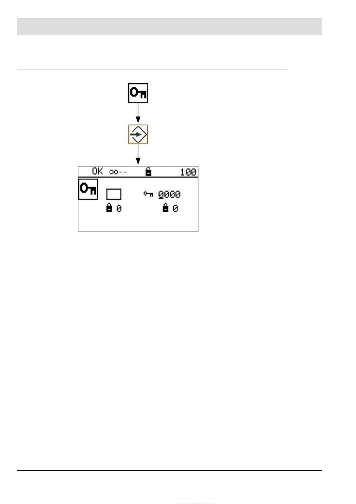
In the main menu, select for the calibration of the probe.
Terminating the cold start prematurely.
By selecting with the cursor key and
ENTER the cold start is terminated prematurely.
The system returns to the main menu automatically.
34
Page 36

6 Commissioning
6.3.5 Reading the Measured Values
In the main menu, select the INFORMATION
menu with .
In the INFORMATION menu, select measured values and probe data with .
In measured values and probe data, select:
Display of the O2 measured values
Display of the COe measured values
Display of the R
resistances
Display of the current fuel
selection
The O2 probe voltage U-O2 stabilises to values between +10 ...-20 mV.
The CO probe voltage U-CO stabilises to
values between +10 ...-20 mV.
internal probe
ki
35
Page 37

6 Commissioning
The Rki internal probe resistance values
lie between 15 ... 25 .
Display of whether the internal probe
resistance regulation is active!
Display of the current heating capacity
P
h
R
S Display of the setpoint value for the
ki
internal resistance regulation.
O2-CO: Evaluates the cross-talk response
between the O2 and CO electrodes.
If the influence is too large (>15 %), the sensor signals overwrite each other. This leads
to measurement faults and triggers Fault
FH007/10 after 30 seconds. A basic influence always exists due to the common GND
of the electrodes.
Currently selected fuel.
36
Page 38

6 Commissioning
6.4 Calibrating the Probe
A correct and regular probe calibration increases measuring precision.
The probes can be calibrated by
• reference measurement or
• test gas
For calibration using a reference measurement, an flue gas analyser is required. The probes
can then be calibrated when installed / whilst combustion is taking place.
For the test gas calibration, the KS1D-HT is be provided with a test gas connection. It can then
be calibrated when installed / whilst combustion is taking place. A testing device is available
for the test gas calibration of the KS1D standard (type 656R2000)(see Chapter 7.1 Checking/
Calibrating the KS1D Combination Probe). Calibration must take place when the probe is disassembled.
The following calibrations must be performed with the probe after commissioning and/or probe
replacement:
1 Offset calibration (required; see Chapter 6.4.1 Offset Calibration)
– Adapts the O2 measured value to the ambient conditions. In the process, a known environment with 21 vol.% O2 must be present.
2O2 calibration (recommended; see Chapter 6.4.2 Calibrating the O2 Electrode)
– Adapts the O2 measured value to the operating conditions around a typical operating
point.
3COe calibration (recommended; see Chapter 6.4.3 Perform a Calibration of the CO/H2
Electrode)
– Adapts the COe measured value to the operating conditions of the combustion system.
NOTICE
For good measuring precision, it must be guaranteed that the correct fuel curve is set for the
system (e.g., BS1 = light fuel oil EL or BS2 = natural gas) during operation and for calibration
with a reference measurement. The factory set fuel curve is natural gas.
NOTICE
For the greatest possible measuring precision, an own burner and fuel specific characteristic
curve can be determined and stored. In order for the generally valid fuel curves BS1 and BS2
not to have to be changed, BS3 is unassigned for this purpose.
Before start the calibration you have to activate maintenance mode. This prevents mishandling faults and deactivate probe faults. The maintenance mode have to be disabled after successful calibration.
37
Page 39

6 Commissioning
6.4.1 Offset Calibration
Before offset calibration, check whether Rki O2 value is equivalent to 20 (see chapter 6.3.5
Reading the Measured Values).
Otherwise, proceed as described in chapter 6.3.3 Response of the Internal Resistance Regulation
Also check the probe voltage U-O2. It must be in the range of +10 ... -20 mV.
To perform an offset calibration, the probe must be located in the ambient air and should run
for at least 30 minutes in a fault-free measuring mode.
No access level is required!
NOTICE
In case of the KS1D-HT (type 656R2015), the offset calibration can also be performed in an
installed state whilst combustion is running. For this purpose, air (dry and oil-free air, instrument air or ambient air) must be fed at connection 10 with a volume of 40 ... 60 l/h for the duration of the calibration.
Activate maintenance!
In the MAIN MENU, select for the calibration of the probe.
In PROBE CALIBRATION, select for the
offset calibration.
38
Page 40

6 Commissioning
Selecting with the cursor key and
ENTER triggers an offset calibration.
Within 10 s, confirm the setting with ENTER
otherwise the value is not assumed.
The U-O2 value stabilises to values between
+10 ... -20 mV.
The Rki internal probe resistance values
lie between 15 ... 25 .
Display of whether the internal probe
resistance regulation is active!
Ph Display of the current heating capacity
R
S Display of the setpoint value for the
ki
internal resistance regulation.
O2-CO: Evaluates the cross-talk response
between the O2 and CO electrodes.
If the influence is too large (>15 %), the sensor signals overwrite each other. This leads
to measurement faults and triggers Fault
FH007/10 after 30 seconds. A basic influence always exists due to the common GND
of the electrodes.
• The offset calibration takes place automatically once triggered
• After a successful calibration, the O2 value is at 21 vol.% O2,
whilst the COe value is at 0 ppm.
• Deactivate maintenance mode; see Chapter 6.3.2 Activate/deactivate Maintenance
Mode.
39
Page 41

6 Commissioning
6.4.2 Calibrating the O2 Electrode
• Activate Maintenance mode.
NOTICE
Access level 1 or 2 required!
NOTICE
When calibrating the O2 electrode in CO containing flue gas the O2 sensors’ Kelvin value
moves outside the permissible range (< 800 ... >1200 K). The warning WH004 or WH104 is
indicated CO temperature is too high/too low.
The calibration have to be repeated on another point of O2 without CO in the flue gas.
The calibration can be performed by reference measurement using an external measuring device or by using test gas at a known O
gas adapter is required.
For the KS1D-HT (Type 656R2015), a hose connection for calibration gas through which the
test gas (40 ... 60 l/h) can be input is available.
A special test gas adapter is not required for this type.
Recommended test gas: 3 vol.% O
concentration. For KS1D type 656R2000 a special test
2
in N2.
2
NOTICE
When performing a reference measurement using an external measuring device, check if the
measuring device is measuring wet or dry. In the case of devices with an upstream measuring
gas cooler, it always concerns a dry measurement. This also applies to devices which remove
the moisture by means of a chemical substance. The KS1D probe measures wet. The difference between a wet to dry measurement is evident from the graphic in the appendix under
13.5 Wet/Dry Measurement Deviations, Conversion Table.
NOTICE
Calibration / checking with a reference measurement functions only
with O2 values < 15 vol. % and > 1 vol. %.
In the Main Menu, select for probe calibration.
40
Page 42

6 Commissioning
• Deactivate MAINTENANCE mode.
6.4.3 Perform a Calibration of the CO/H2 Electrode
• Activate maintenance mode.
NOTICE
Access level 1 or 2 required!
In Probe Calibration, select for O
cali-
2
bration.
With , , , change the O
val-
2
ues of the probe.
Within 5 s, confirm the calibration with
otherwise the calibration is not assumed.
The calibration can be performed by reference measurement using an external measuring device or using test gas in combination with a testing device (type 650R1015) of test gas at a
known COe concentration.
For KS1D type 656R2000, a special adapter for test gas is necessary. (For the required test
gas adapter for the KS1D (Type 656R2000), see Chapter 7.1.4 Checking/Calibrating with Test
Gas).
Recommended test gas: 3 vol.% O2, 200 ppm CO, 100 ppm H2, in N
2
COe value to be set: 300 ppm
A test gas without O2 cannot be used for the calibration. The test gas must always contain O2
in the % area.
For the KS1D-HT (Type 656R2015), a hose connection for calibration gas through which the
test gas (40 ... 60 l/h) can be input is available.
NOTICE
Calibration / checking with a reference measurement functions only with COe values
>100 ppm.
41
Page 43

6 Commissioning
In the MAIN MENU, select for the calibration of the probe.
In PROBE CALIBRATION select for
COe calibration.
With the keys , , , change the
COe values.
Within 5 s, confirm the calibration with
otherwise the calibration is not assumed.
The probe is now ready for operation.
Deactivate maintenance mode; see Chapter 6.3.2 Activate/deactivate Maintenance Mode.
42
Page 44

6 Commissioning
6.5 Settings
According to which access level you are located, you can make various settings. In access
level 2 (Service), all settings can be made.
In the MAIN MENU, select to make settings.
SETTINGS, offers the following setting possibilities:
Maintenance mode (Level 0); see Chap-
ter
6.5.1 Maintenance Mode
Filter time of the measured values
(Level 0).
Analogue outputs (Level 1); see
Chapter 5 Display and Operational Con-
trols
Probe replacement (level 1).
COe response threshold (Level 2).
Display (Level 0).
Limit values (Level 1).
Digital outputs (Level 2).
6.5.1 Maintenance Mode
In SETTINGS select (see Chapter 6.3.2 Activate/deactivate Maintenance Mode.)
6.5.2 Filter Time
Filter time of the measured values:
No access level is required to make this set-
ting.
Time over which the measured values are
determined
(in an integrated manner).
Factory setting:
O2 measured value 2 seconds
COe measured value 10 seconds
43
Page 45

6 Commissioning
6.5.3 Analogue Outputs
In SETTINGS select for analogue outputs (see Chapter 10.1.3 Conversion of the Output
Range via the User Interface).
6.5.4 Replacing a Probe
Probe replacement:
A minimum of access level 1 is required for
triggering.
(See Chapter 7.2 Replacing a Probe.)
6.5.5 Display
Display:
No access level is required to make this set-
ting.
Brightness
Contrast
Time in seconds until the
background lighting extinguishes
Switchover °C/°F
44
Page 46

6 Commissioning
6.5.6 Limit Values
NOTICE
Access level 1 or 2 required!
Limit values
Proceed with the key.
Control of the entry with the following key
sequence:
, , , .
Limit value off
Monitoring of exceeding
Monitoring of undershooting
Setting of limit value
Setting of trigger time of limit value
NO - limit value resets automatically
YES - manual acknowledgement of limit value required (see Chapter 5.4
Main Menu
45
Page 47

6 Commissioning
If a limit value is undershot/exceeded, this is indicated in the status line by a down/up arrow
(see Chapter 5.3 Status Line).
In addition, the following message appears on the display:
Limit value 1:
• Factory setting: Exceeding of 400 ppm CO
Limit value 2:
• Factory setting: Undershooting of 0.5% O2, 30 s
Key returns to the main display
, 60 s
e
46
Page 48

6 Commissioning
6.6 Test Certificate
Each probe is accompanied with a test certificate. This means that you can compare the current measured values against test bench values at any time.
47
Page 49

6 Commissioning
6.7 Probe Certificate
A probe certificate is included with each probe. This should be completed during commissioning. The probe certificate must always be enclosed in the event of complaints and for repairs.
NOTICE
No probe certificate included with the probe, no goodwill!
Fig. 6-1 Probe certificate for the KS1D probe
48
Page 50

7 Maintenance
7 Maintenance
As a result of extensive self-diagnosis, the measuring system is essentially maintenance-free.
Maintenance is restricted to the calibration and the cleaning of dust or other deposits; as well
as the cyclic replacement of the ZrO2 measuring element.
7.1 Checking/Calibrating the KS1D Combination Probe
The checking / calibration should (advantageously installed) be built in at normal operating
temperature and carried out under operating conditions.
Recommended time spans (cycles):
• 6 hours after commissioning
• 12 months for natural gas combustion systems
7.1.1 Checking/Calibrating the Air Voltage (Offset)
1. Switch off the plant.
If you cannot switch off the plant, the probe must be dismantled. Observe the safety no-
tices!
2. Pre-ventilate, until there is no longer any flue gas at the measuring point (about 1 minute).
3. End the pre-purge.
4. Perform the offset calibration of the O2 (U-O2) and CO/H2 (U-CO) electrodes.
See Chapter 6.4.1 Offset Calibration.
7.1.2 Checking/Calibrating the O2 Electrode
See Chapter 6.4.2 Calibrating the O2 Electrode.
7.1.3 Checking/Calibrating the CO/H2 Electrode
See Chapter 6.4.3 Perform a Calibration of the CO/H2 Electrode.
49
Page 51

7 Maintenance
7.1.4 Checking/Calibrating with Test Gas
WARNING!
Danger of burns!
Probe becomes hot during operation.
If the probe is operated when removed, there is a danger of burns on the probe housing.
Never lay the probe on flammable material and heat it up.
Wear protective gloves
Description of the Testing Device
General Information:
The probe signals are pressure-dependent so they must be tested in a pressure-free environment. The testing device takes this into consideration and guarantees the best results in specific ranges. In exceptional cases, the pressure of the testing device must be adjusted to the
pressure of the measuring point through an additional device.
Choose a test gas combination so that O2 or COe content lies in the usual plant specific range
and within the specified measuring range of the probe. In standard applications in the combustion technology, O2 concentration lies at 2-5 vol.% and COe concentration lies between
100 ... 500 ppm. The following indicated test gas composition guarantees best results.
Description:
The testing device is a device for the task of testing gases on the probes LS1/KS1/KS1D in
standard housing. The probe can be tested or calibrated by means of test gas function.
The testing device can used lying on the table or plugged into the flue gas channel (Fig. 7-1
Testing device laying on the table and Fig. 7-2 Testing device plugged into flue gas channel.
For gas-tight fixing at the flue gas channel, the probe screw joints (clamping ring/screw cap)
can be attached to the plug in nozzle for flue gas channel.
50
Page 52

7 Maintenance
Fig. 7-1 Testing device laying on the table
1 Probe LS2, KS1, KS1D
2 Test gas connection
3 Plug in nozzle for flue gas channel
4 Test gas outlet
Fig. 7-2 Testing device plugged into flue gas channel
51
Page 53

7 Maintenance
Test probe
1. Install probe:
2. Heat up probe:
The testing device with plugged in heated probe would get hot.
Risk of burning!
3. Test gas function:
NOTICE
For test gas usage of 2 bar, test gas pressure lies at 1.6 l/min and increases at 0.6 l/min per
bar increase in pressure.
Push probe into the testing device until stop.
A cold probe should be heated up for at least 45 minutes in the installed condition. Should
an already heated up probe be installed in the testing device, then wait for 15 minutes.
CAUTION!
The test gas connection would be connected to the pressure reducer or the compressed
air supply of the test gas bottle using hose or hose clamp (D
sponding test gas is to be given up with 2 1 bar (pressure behind the bottle pressure
reducer). After 2 minutes, the probe calibration and testing can take place.
=4; Da=6mm). The corre-
i
CAUTION!
With the usage of CO containing test gases C, these must be removed from the test gas outlet
e.g. by the exhaust hose.
4. Calibration/probe testing:
According to table 4, LS2 is to be tested within 2 steps while KS1/KS1D in 3 steps.
a) Offset testing/calibration
Compare oxygen values of probe and test gas A.
Should the deviation of oxygen value be less than or equal to 0.2 vol.% of 21 vol.%,
the probe is fine.
Should the deviation of oxygen value be more than 0.2 vol.%, the probe must be calibrated according to the manual.
b) O2 testing/calibration
Compare oxygen values of probe and test gas B.
Should the deviation of oxygen value be less than or equal to 0.1 vol.% of 3 vol.%, the
probe is fine.
Should the deviation of oxygen value be more than 0.1 vol.%, the probe must be calibrated according to the manual.
c) CO/H2 testing/calibration
If the probe reacts to an increase in probe voltage on test gas C, then the probe is fine.
If the probe does not react, it has to be changed.
Compare CO value of the probe and COe-value of test gas C.
If COe value of the probe lies between 275 … 375 ppm, the estimation of COe value
is fine. Otherwise, calibrate a more precise estimation of the probe according to the
manual. calibrate on 300ppm.
NOTICE
CO/H2 calibration with test gas C has the advantage of determining and compensating the
long term drift of sensitivity. The sensitivity of the CO/H2 electrode usually increases over time
safe direction!
52
Page 54

7 Maintenance
NOTICE
With KS1D HT (item no. 656R2015), the test gas to be tested/calibrated can be connected
directly at the hose connection for calibration gas. A special testing device is not necessary.
The required test gas quantity lies between 40 ... 60 l/h.
Probe calibrated
Test gas matrix for testing or calibrating the respective probe
Functional
Probe
chrck/calibration with test
gas
Probe voltage U-O
Probe voltage U-CO probe voltage U-
2
CO
e
1 Offset A A A
2 OBBB
3 CO/H
2
CCC
Test gas composition
Composition
Test gas
**
A
O2 [Vol.%] COe [ppm]
21 0 Rest
*
N2 [Vol.%]
B 3 0 Rest
C 3 300 Rest
* CO Equivalent COe is the sum of all components in the exhaust gas. In test gases, it is represented
by CO and H2 in proportion of 2:1, e.g. 300ppm COe = 200 ppm CO +100 ppm H2.
** In the test gas device, the probe can be calibrated/tested with oil-free pressure air or synthethic air
from test gas bottle. In a COe-free and defined surrounding, the probe can also be tested/calibrated outside of the test gas device.
Recommendation:
To check the O2 electrode, use a test gas with 3 vol. % O2 in N2.
NOTICE
It is not possible to calibrate the CO/H2 electrode using hydrogen free test gas containing CO.
Recommendation:
To check the CO/H2, use a test gas with 100 ppm H2, 200 ppm CO, and 3 % O2 in N2.
Calibrate to 300 ppm.
For the standard design of the KS1D combination probe, a special testing device is required
(type 650R1015). For calibration adjust the pressure on the pressure gauge between
40 ... 60 mbar.
NOTICE
The pressure gauge is a very sensitive measuring device.
Protect it against overload. Pay attention to the pressure range!
53
Page 55

7 Maintenance
Risk of poisoning by carbon monoxide!
Carbon monoxide is a poisonous gas. Inhalation can cause severe poisoning symptoms an
can be fatal.
Perform the calibration quickly and only in open, well-ventilated rooms, ideally underneath
Do not open the valve on the test gas cylinder until shortly before calibration and close it
Danger of burns!
Probe becomes hot during operation.
If the probe is operated when removed, there is a danger of burns on the probe housing.
Never lay the probe on flammable material and heat it up.
Wear protective gloves
WARNING!
an exhaust hood.
immediately after calibration!
WARNING!
7.1.5 Checking/Calibrating with Reference Measurement
• The system must be in operation (ideally at the desired operating point).
• Perform the calibration as described in Chapters 6.4.2 Calibrating the O2 Electrode and
6.4.3 Perform a Calibration of the CO/H2 Electrode .
7.1.6 Simple Function Test of the CO/H2 Electrode
WARNING!
Danger of burns!
If a dismantled probe is operated, there is a danger of burns if touching the probe’ s housing.
Never lay the probe on flammable material and heat it up.
Wear protective gloves
1. Dismantle the probe
2. Fill isopropyl alcohol in a glass (approx. 1 cm)
Alternatively, use brandy/perfume / etc.
3. Hold the probe without the GED upside down into the glass.
Do not immerse!
NOTICE
An additional possibility is to purge the probe with test gas containing CO, NO, H2, etc.
Some ppm are enough.
If the probe is OK, this immediately reacts with a considerable increase in the probe voltage
(COe value) respective to the probe dynamic response.
54
Page 56

7 Maintenance
7.1.7 Wear-and-Tear Parts of the KS1D Combination Probe
Average life cycle = 2 - 3 years (depending on fuel).
Recommendation:
Exchange the ZrO
A worn measuring gauge could cause errors while calibrating and therefore impede the precision of measurement.
The combination probe KS1D type 656R2000 with housing and type 656R2010 without housing can only be replaced completely
.For combination probe KS1D HT (high temperature) type 656R2015, a replacement kit is
available. Order no. 656R2065.
measuring cell after 5 years at the latest.
2
Probe dynamic response
55
Page 57

7 Maintenance
7.2 Replacing a Probe
A probe must be replaced if:
• The internal resistances Rki-O2 and Rki-CO can no longer be set to values
of 20 Ω (+/- 5 Ω).
To be read at the probe data (Menu 213).
• The probe offset voltages U-O2 and U-CO in the air assume values above +20 mV or
below -30 mV.
To be read at the probe data (Menus 211 and 212).
• The CO/H2 electrode does not response
In the MAIN MENU, select for information.
In INFORMATION select for measured
values and probe data.
In MEASURED VALUES and Probe Data the
following is available for selection:
Display of the O2 measured values
(menu 211)
Display of the CO measured values
(menu 212)
Display of the Rki internal probe
resistances (menu 213)
Display of the current fuel selection
Reading of O2 measured values.
56
Page 58

7 Maintenance
Reading of CO
Reading of the R
ances.
NOTICE
After the exchange of the probe, a probe replacement must be triggered immediately after
reactivation!
• A minimum of access level 1 is required
measured values.
e
internal probe resist-
ki
In the MAIN MENU, select to make settings.
In SETTINGS, select for probe replacement.
57
Page 59

7 Maintenance
After the successful triggering of a probe exchange, the heating capacity and Rki are reset to
the standard values and can be learnt by the system again.
After that, start up the probe as in the initial start-up, as described in Chapter 6 Commission-
ing.
7.3 Sensor Replacement KS1D-HT
To replace the sensor in the KS1D-HT probe a replacement kit type 656R2065 is available.
The replacement kit includes:
• KS1D-HT probe
• Seal for probe
• Filter disc
• Seal Novaphit
By selecting with the cursor key
and ENTER a probe replacement is trig-
gered.
Sensor replacement KS1D-HT (replacement kit 656R2065)
Disconnect the probe and check the connection
Check temperature of probe/sensor and if necessary cool down
Insulation slot screwdriver size 0,4 x 8 x 100 mm
Torque wrench 3,5 Nm with attachment for Allan key
Open-end wrench 24 mm
Allan key 3 mm
1. Loose the connection cable in the probe head Fig. 7-3 Probe head.
2. Loose Allan key and remove them remove probe head Fig. 7-4 Sensor without probe
head
3. Remove sensor and seal Fig. 7-5 Sensor Ein-/Ausbau installation/dismounting and Fig. 7-
6 Ausgebauter Sensor mit Dichtring Dismounted sensor with seal.
4. Unscrew filter cap and remove filter Fig. 7-7 Sensorhalter mit Filterkappe und Filter sensor
holder with filter cap and filter.
5. Replace filter, screw on filter cap.
6. Insert sensor with seal.
7. Put on the probe head and fasten with screws (tightening torque 3.5 Nm
NOTICE
Please note the tightening torque 3.5 Nm!
8. Reconnect connecting cable, see Fig. 7-8 Klemmsockel bei KS1D-HT terminal socket
KS1D-HT
58
Page 60

7 Maintenance
NOTICE
Note the connection diagram and markings on terminal socket!
9. Close probe head.
The probe with a new sensor is ready to use.
Fig. 7-3 Probe head
Fig. 7-5 Mounting/dismounting the sensor
Fig. 7-4 Sensor without probe head
Fig. 7-6 Dismounted sensor with seal
59
Page 61

7 Maintenance
Fig. 7-7 Sensor holder with filter cap and filter
Fig. 7-8 Terminal socket KS1D-HT
1 (-) probe signal O2 (red)
3 (-) probe signal CO (grey)
4 (+) probe signal CO/O2 (black)
5 probe heater (white)
6 probe heater (white)
60
Page 62

8 Correcting Faults
8 Correcting Faults
8.1 Faults and Warnings
Faults are indicated by the red flashing of the ENTER key and shown in the display. After the
ENTER key is pressed, faults can be reset.
NOTICE
In the case of faults that cannot be allocated, data records can be read with LSB remote software and sent to LAMTEC for analysis!
F
Fault
W
Warning
H
Main processor
U
Monitoring processor
001
Fault number
Probe/probe voltage fault
/1
Trigger 1
NOTICE
Each fault can occur as a temporary or permanent fault. Temporary faults reset themselves
automatically when the corresponding values lie within the permissible range again.
If temporary faults are present for longer than 30 minutes or repeat several times within an
hour, they become permanent faults. A permanent fault remains even after switching voltage
off and on again. Permanent faults must be reset manually. After a fault reset, the device resets and starts again in COLD START mode.
Fault 001 Fault 002 - 008 Fault 015 - 016
Number of triggers,
temporary
Time window 60 min 60 min 60 min
Permanent time 30 min 30 min 30 min
10 x for at least 10 s 3 x for at least 10 s Immediately
61
Page 63

8 Correcting Faults
8.1.1 Faults
Deactivation during maintenance: Safety transfer O2, limit values, fault 001, 002, 004,
005, 007, 008.
Fault no. Fault text
001 (HP)
101 (ÜP)
/1 Voltage range of O2 electrode outside of the permissible range.
/2 Voltage range of CO electrode outside of the permissible range.
/3 O2 offset voltage outside of the permissible range during pre-purge
/4 CO offset voltage outside of the permissible range during pre-purge. The
/5 Both offset voltages outside of the permissible range during pre-purge; see
Probe/probe voltage fault
U-O2 must always lie within a range of -25 mV ... +300 mV during measurement operation; tolerance time of 30 seconds.
Help:
- The cold start might have been interrupted therefore the probe is not yet
ready for operation.
- Remove the probe and check with ambient air and test gas.
Compare the values with the test report. Exchange the probe if required.
- If the O2 electrode reacts to CO, the sensor is defective; exchange the
probe.
U-CO must always lie within a range of -25 mV ... +800 mV during measurement operation; tolerance time of 30 seconds.
Help:
- The cold start might have been interrupted therefore the probe is not yet
ready for operation.
- Remove the probe and check with ambient air and test gas.
Compare the values with the test report. Exchange the probe as required.
The offset voltage of the O2 electrode must always lie within a range of
-25 mV ... +5 mV during pre-purge.
Help:
- The cold start might have been interrupted therefore the probe is not yet
ready for operation.
- Remove the probe and check with ambient air and test gas.
Compare the values with the test report. Exchange the probe if required.
- The probe is blown "cold": unfavourable installation site.
offset voltage of the CO electrode must always lie within a range of
-25 mV ... +10 mV during pre-purge.
Help:
- The cold start might have been interrupted therefore the probe is not yet
ready for operation.
- Remove the probe and check with ambient air and test gas.
Compare the values with the test report. Exchange the probe if required.
- The probe is blown "cold": unfavourable installation site.
triggers /3 and /4.
62
Page 64

8 Correcting Faults
/6 CO voltage smaller than O
/7 O2 value over 25%
/8 Dynamism only at O
Help:
- The cold start might have been interrupted therefore the probe is not yet
ready for operation.
- Remove the probe and check with ambient air and test gas.
Compare the values with the test report. Exchange the probe if required.
- The probe is blown "cold": unfavourable installation site.
voltage
2
Offset-adjusted CO probe voltage more than 10 mV smaller than offsetadjusted O2 probe voltage; tolerance time of 28 seconds.
Help:
- Exchange the probe.
- Check the wiring of the sensors, maybe O2 and CO are inverted
The O
value rises to over 25% after the deactivation of the burner;
2
tolerance time of 15 seconds.
Help:
- Wait to see whether the value stabilises at 21%.
- If not, remove the probe and perform an offset calibration in the air.
- Installation site possibly unfavourable; the probe is possibly blown "cold."
electrode
2
The O2 electrode demonstrate dynamism without the CO electrode show-
ing dynamism; tolerance time of 30 seconds.
Help:
- Monitoring active only in case of values < 16 vol. % O2
- The probe no longer reacts to changes.
- Remove the probe and check for soiling of the grille.
- Check the O2 value in the ambient air and/or with test gas.
- If the O2 value is <16% in the ambient air, perform an
offset calibration.
- In case of no changes, exchange the probe.
/9 Missing CO dynamism or U-COe
U-O2 over 200 mV longer than 15 seconds without CO dynamism or UCOe
20 mV
Help:
- Monitoring active only in case of values < 16 vol. % O2
- The probe no longer reacts to changes.
- Remove the probe and check for soiling of the grille.
- Check with ambient air and test gas if pertinent.
- In case of no changes, exchange the probe.
/10 O2 voltage limit value
O2voltage U- O2 > 100 mV for more than 60 seconds.
/11 CO voltage limit value
CO voltage U- CO > 200 mV for more than 120 seconds.
/14 UCOe monitoring
COe voltage U-COe > 300 mV, tolerance time of 27 seconds, up to 117
seconds in case of dropping voltage.
Help:
- Activate maintenance mode in case of a test gas connection.
/15 The O2 voltage does not demonstrate the required dynamism.
Change in the O2 voltage U-O2 less than 2.5% within 24 hours whilst the
O2 or CO controller is running.
63
Page 65

8 Correcting Faults
/16 The CO voltage does not demonstrate the required dynamism.
Change in the CO voltage U-CO less than 2.5% or 8 mV within 24 hours
whilst the O2 or CO controller is running.
002 (HP)
102 (ÜP)
/1 The heater is short-circuited or has a high resistance; tolerance time of 10
/2 Heating power more than 15 s outside of the permitted range
/3 Heater Ri outside of 5 ... 15
/4 OFF current too high
Probe heating fault
seconds
Help:
- Check the wiring.
LT3-F Term. 13 and 14 disconnect the probe - probe heating at LT3-Ex
or in SAK
and measure the heater resistance between wire nos. 13 and 14
on the probe side.
Resistance approx. 9 ... 10 in heated state.
- If not OK, exchange the probe and restart.
- If OK, the fault presumably lies on the motherboard of LT3-F.
If the lines of the probe heating and probe signal are mixed up
during connection (possible in the case of the SAK wiring), the mother
board is destroyed. Disconnect the probe and measure the heating
voltage: approx. 11V
(8W … 25 W)
Help:
Installation site too hot: the heating capacity cannot be further reduced
(current actual value of R
internal resistance Rki of 20 or
Installation site too cold: the heating capacity cannot be further increased
(current actual value of Ri > 20) to reached the setpoint value of the
internal resistance Rki of 20 . Check the value of the internal resistance
Rki in the display.
- Trigger the probe exchange and restart the probe so that the Rki of
20 can be learnt again.
- Check the system temperature at the installation site.
- Check the probe when removed if pertinent.
- Exchange the worn probe if pertinent.
- As a follow-up fault, 002/3 Heater Ri outside of 5 ... 15 might be
displayed.
Internal resistance of heater outside of the interval 5 ... 15
Help:
Installation site too hot: the heating capacity cannot be further reduced
(current actual value of Ri < 20 ) to reached the setpoint value of the
internal resistance Rki of 20 . Check the value of the internal resistance
Rki in the display.
- Trigger the probe exchange and restart the probe so that the Rki of
20 can be learnt again.
- Check the system temperature at the installation site.
- Check the probe when removed if pertinent.
- Exchange the worn probe if pertinent.
As a follow-up fault, 002/2 Heating capacity outside of permissible interval
(8 W ... 25 W) for longer than 15 s might be displayed.
< 20 ) to reached the setpoint value of the
i
64
Page 66

8 Correcting Faults
/5 Heating control circuit open
/6 Temperature of the O
/7 Temperature of the CO sensor too high (Rki-CO too low)
003 (HP)
103 (ÜP)
004 (HP)
104 (ÜP)
/1 R
/2 Rki O2 too low. Internal resistance of ceramics of O2 under 10 , tolerance
005 (HP)
105 (ÜP)
/1 Rki-CO too high. Internal resistance of ceramics of CO for LT3-F over 50 ,
/2 Rki-CO too low. Internal resistance of ceramics of O2 under 10 , toler-
Heater controller at limit stop for longer than 30 seconds.
Help:
Check wiring between probe and LT3-F (check probe signals terminals 10/
11/12)
sensor too high (Rki-O2 too low)
2
For longer than 10 seconds, Rki-O2 is under 10
Heater Ri outside of 5 ... 15
Internal resistance of heater outside of the interval 5 ... 15
For longer than 10 seconds, Rki-CO is under 10
Internal fault of analogue signal processing
Device defective
- Contact the manufacturer. Specify the trigger for diagnostic purposes.
Internal resistance of ceramics of the O
too high. Internal resistance of ceramics of O2 for LT3-F over 50 ,
ki O2
electrode
2
and/or for LT3 over 100 , tolerance time of 30 seconds.
time of 30 seconds.
Help:
If Rki-O2 for LT3-F over 50 , and/or for LT3 over 100 , then
- Probe too cold.
- Internal resistance regulation not active or incorrect setpoint value.
- The probe is stuck in a cold spot and the heating capacity does not suf-
fice.
Look for a new installation position.
- Flow speed too high.
- Heating defective and probe cold.
- Sensor breakage.
- Check wiring between probe and LT3-F
(signal terminals 10/11/12)
If Rki-O2 under 10 , probe is too hot, internal resistance regulation is not
active, or incorrect setpoint value.
The optimum operating point (setpoint value) lies at 20 .
Internal resistance of ceramics of the CO/H2 electrode
and/or for LT3 over 100 , tolerance time of 30 seconds.
ance time of 30 seconds.
65
Page 67

8 Correcting Faults
Help:
If Rki-CO for LT3-F over 50 , and/or for LT3 over 100 , then
- Probe too cold.
- Internal resistance regulation not active or incorrect setpoint value.
- The probe is stuck in a cold spot and the heating capacity does not
suffice.
Look for a new installation position.
- Heating defective and probe cold.
- Sensor breakage.
-CO under 10 , then probe too hot.
If R
ki
- Internal resistance regulation not active or incorrect setpoint value.
The optimum operating point (setpoint value) lies at 20
007 (HP)
107 (ÜP)
008 (HP)
108 (ÜP)
014 (HP)
114 (ÜP)
015 (HP)
115 (ÜP)
016 (HP)
116 (HP)
Probe insulation
Device or probe defective.
Contact the manufacturer and specify the trigger for diagnostic purposes.
Help:
- Remove the probe and check it in ambient air.
- Check the wiring between LT3-F and probe (sensor signal
and terminals 10/11/12)
- Probe and LT3-F at the same potential?
- Exchange the probe.
Intern fault: measured value comparison HP/UP
Device defective; contact the manufacturer and specify the trigger for diagnostic purposes.
Write the data record
Parameter/EEPROM fault
Device defective. Contact the manufacturer and specify the trigger for
diagnostic purposes.
Internal fault/self tests
Device defective. Contact the manufacturer and specify the trigger for
diagnostic purposes.
66
Page 68

8 Correcting Faults
8.1.2 Warnings
Warning no. Warning text
001 (HP)
101 (ÜP)
/1 - 29999 Trigger value of the O2 offset voltage in the air (x0.1 mV)
002 (HP)
102 (ÜP)
/1 - 29999 Trigger value of the CO offset voltage in the air (x0.1mV)
003 (HP)
103 (ÜP)
/1 - 29999 Trigger value of the O2 temperature (x0.1 K)
004 (HP)
104 ÜP
/1 - 29999 Trigger value of the CO temperature (x0.1 K)
005 (HP)
105 (ÜP)
/1 CO value not assumed, CO setpoint value too small
/2 CO value not assumed, division by zero
/3 CO value not assumed, calibration scaling factor outside of the valid
/4 CO value not assumed, value is zero
010 (HP)
110 (ÜP)
/0 - 65535 Trigger value of current internal resistance (x0.1 ),
011 (HP)
111(ÜP)
/0 - 65535 Trigger value of current internal resistance (x0.1 ,
016 (HP)
116 (ÜP)
O2 offset voltage in the air too large or too small
CO offset voltage in the air too large or too small
O2 temperature too large or too small, was not assumed
CO temperature too large or too small, was not assumed
Help:
When calibrating the O2 electrode in CO containing flue gas the O2 sensors’ Kelvin value moves outside the permissible range
(< 800 ... >1200 K). The warning WH004 or WH104 is indicated CO
temperature is too high/too low.
The calibration have to be repeated on another point of O2 without CO in
the flue gas.
CO scaling
range
Help:
CO sensor worn/poisoned. Exchange the probe.
For LT3-F: Internal resistance of ceramics of the O2 electrode
over 45 Ω
For LT3: Internal resistance of ceramics of the O2 electrode
over 80 Ω
tolerance time of 3 seconds.
For LT3-F: Internal resistance of ceramics of the CO electrode
over 45 Ω
For LT3: Internal resistance of ceramics of the CO electrode
over 80 Ω
tolerance time of 3 seconds.
Internal warning
67
Page 69

8 Correcting Faults
Warning no. Warning text
/1 Serial number, customer ID or service password reset.
Contact the manufacturer.
Display if customer ID in LT3 and UI do not correspond.
68
Page 70

8 Correcting Faults
8.1.3 Call of the Fault History
In the MAIN MENU select for information.
In INFORMATION select for the fault
history.
Fault history
01 Number of the entry
001 Fault number of the main processor
If the fault number is displayed as "101"
(+100), there is a fault in the monitoring
processor.
1 Trigger 1
0h Occurs in case of ... Operating hours
For fault numbers, see Chapter 8.1.1 Faults.
69
Page 71

9 Decommissioning
9 Decommissioning
9.1 Decommissioning
9.1.1 Protection Against Emissions from Gas Carrying Channels
Recommendation in case of breaks in operation:
• With longer breaks in operation, in excess of 3 months, switch off the measuring system.
• Removal prevents damage to the probe.
• In the case of briefer breaks in operation, it is recommended that you continue to allow the
measuring system to run.
The KS1D combination probe is fitted directly to the gas-carrying channel via the probe installation fitting (PIF). If the KS1D combination probe or the probe installation fitting (PIF) are dismantled, depending on the plant but particularly in the case of excess pressure, aggressive
and / or hot gas can seep out of the channel and pose a serious health hazard to an unprotected operator if suitable safety measures have not be taken previously.
WARNING!
Risk of burning due to hot gases!
In the case of excess pressure and temperatures in excess of 200 °C in the gas channel, gases could escape when dismantling the KS1D combination probe or the probe installation fitting
(PIF).
Before opening, shut down the system.
Wear suitable protective clothing and a protective mask.
Fix respective warning information in close proximity to the mounting site.
Immediately seal the opening again.
The LT3-F lambda transmitter and the KS1D combination probe are a high-quality, electronic
measuring system. It therefore requires careful handling in all situations - decommissioning,
transport and storage.
NOTICE
Do not switch off the LT3-F lambda transmitter as long as the KS1D combination probe is
mounted. Not even if the associated plant has been brought to a standstill. Residual gases will
cause corrosion and could damage system components.
Do not store the device outside without any protection!
When uninstalling, protect the ends of cables and the connectors from corrosion and soil-
ing. Corroded connectors can cause malfunctions.
Always store in a dry location and, if possible, keep in the original packaging.
If possible, always transport in the original packaging.
NOTICE
The KS1D combination probe is capable of being stored in a dismantled state.
This also applies if a KS1D combination probe has already been in operation once.
70
Page 72

10 Options
10 Options
10.1 Analogue Outputs via LSB Module Current, alternative Voltage, LSB address 19
10.1.1 Functional Description
• Current module: 4 analogue outputs 0/4 ... 20 mA
• Voltage module: 4 analogue outputs 0/2 ... 10 VDC
• Possible to quickly wire several modules by means of strapping plugs
The LSB modules are universally applicable output modules, which are controlled via the LSB
SYSTEM BUS. In the process, the module is triggered by an adjustable address
(1 - 99). The statuses of the outputs are transferred in the data bytes. If an analogue output
module with the same address exists in the system, the voltage / current measured there is
shown on the respective output.
NOTICE
All outgoing lines from the LSB module must be screened. The screens must be applied to the
PE rail as short as possible.
NOTICE
The termination resistor (120 ) must be installed and activated on the first and the last BUS
device.
Avoid transmission line!
71
Page 73

10 Options
1 Analogue output module Terminal assignment:
2 LSB terminal resistance, 120 1+ / 1- Analogue output 1
3 Rotary switch for setting the tens
LSB address
4 Rotary switch for setting the ones
LSB address
5 Jumper plug 4+ / 4- Analogue output 4
2+ / 2- Analogue output 2
3+ / 3- Analogue output 3
24 VDC Voltage supply for LT3-F Termi-
nals 77-/78+
CAN H/L LAMTEC SYSTEM BUS for LT3-F
Terminals 74 H/75 L
10.1.2 Factory Setting of Analogue Outputs via LSB Module
The module is activated at the factory.
In case of a later installation or exchange, the LSB address 19 must be set on the module using only 2 rotary switches.
Analogue output 1 (O2 measured value)
• Setting range adjustable between 0 ... 25% O
• Factory setting: 0 ... 10 vol.% O2 4 ... 20 mA
Analogue output 2 (COe measured value)
• Setting range adjustable between 0 ... 30,000 ppm
• Factory setting: 0 ... 1,000 ppm 4 ... 20 mA
Analogue outputs 3 and 4 are currently deactivated at the factory and/or reserved for other
values, such as flue gas temperature and efficiency.
2
72
Page 74

10 Options
10.1.3 Conversion of the Output Range via the User Interface
Access level 1 required.
In the MAIN MENU, select to make settings.
In SETTINGS, select for analogue outputs.
Analogue outputs offer setting possibilities
for
current range or voltage range.
Output range.
Selection of the current or voltage range
according to module.
Output ranges for:
O2 = O2 measured value
COe= COe measured value
η = efficiency
T-ex = flue gas temperature
73
Page 75

10 Options
10.2 Digital Outputs via LSB Module, LSB Address 03 and 51
10.2.1 Functional Description
• 4 relay outputs 250 VAC, 6 A.
• Possible to quickly wire several modules by means of jumper plugs.
• The relay outputs are activated manually using switches.
LSB modules are universally applicable output modules for DIN rail mounting. They are actuated via the LSB. The module is addressed via a settable address (1 ... 99). The data bytes
convey whether data is required or commands are to be executed.
NOTICE
All outgoing lines from the LSB module must be screened. The screens must be applied to the
PE rail as short as possible.
NOTICE
The termination resistor (120 ) must be installed and activated on the first and the last BUS
device.
Avoid transmission line!
74
Page 76

10 Options
1 Digital output module
2 LSB terminal resistance 120
3 Rotary switch for setting the
tens LSB address
4 Rotary switch for setting the ones
LSB address
5 Jumper plug
6 Manual activation
Terminal assignment:
13/14
23/24
33/34
43/44
24 VDC
CAN H/L
Relay output 1
Relay output 2
Relay output 3
Relay output 4
Voltage supply for LT3-F Termi-
nals 77-/78+
LAMTEC SYSTEM BUS for LT3-
F Terminals 74 H/75 L
75
Page 77

10 Options
10.2.2 Factory Setting of the Digital Outputs
The LSB module for digital outputs 1 ... 4 is activated at the factory. In case of a later installation or exchange, the LSB address 03 must be set on the module using only 2 rotary switches.
Digital output 1
Term. 13/14
Digital output 2
Term. 23/24
Digital output 3
Term. 33/34
Digital output 4
Term. 43/44
The LSB module for digital outputs 5 ... 8 is activated at the factory. In case of a later installation or exchange, the LSB address 51 must be set on the module using only 2 rotary switches.
Digital output 5
Term. 13/14
Digital output 6
Term. 23/24
Digital output 7
Term. 33/34
Digital output 8
Term. 43/44
10.2.3 Diagnosis of the Digital Outputs
Locked faults
Warning
Limit value 1 (exceeding of 400 ppm COe, 60 s)
Limit value 2 (undershooting of 0.5 vol. % O2, 30 s)
Calibration
Cold start
Measure
Warning
4 LED above the switches indicate the switching state of the digital outputs.
NOTICE
Manual activation of the relay outputs:
Position 1output contact always closed
Position Aoutput contact switches via LSB
Position 0 output contact always open
76
Page 78

10 Options
10.3 Digital Inputs via the LSB Module, LSB Address 11 and 55
10.3.1 Functional Description
• 4 floating digital inputs per module
• 8 digital inputs possible (2 modules)
• The digital inputs are activated manually using switches.
LSB modules are universally applicable output modules for DIN rail mounting. They are actu-
ated via the LSB. The module is addressed via a settable address (1 ... 99). The data bytes
convey whether data is required or commands are to be executed.
NOTICE
All outgoing lines from the LSB module must be screened. The screens must be applied to the
PE rail as short as possible.
NOTICE
The termination resistor (120 ) must be installed and activated on the first and the last BUS
device.
Avoid transmission line!
1 Digital input module
Input 1 ... 4, address 11
Input 5 ... 8, address 55
2 LSB terminal resistance, 120
3 Rotary switch for setting the tens
LSB address
4 Rotary switch for setting the ones
LSB address
5 Jumper plug
6 Manual activation
77
Terminal assignment:
1+/1-
2+/2-
3+/3-
4+/4-
24 VDC
CAN H/L
Digital input 1
Digital input 2
Digital input 3
Digital input 4
Power supply
for LT3-F Terminals 77-/78+
LAMTEC SYSTEM BUS
for LT3-F Terminals 74 H/75 L
Page 79

10 Options
10.3.2 Factory Settings of the Digital Inputs
Digital input 1 Trigger OFFSET CALIBRATION
Digital input 2 RESET FAULT
Digital input 3 SWITCHOVER to COe curve FUEL 1
Digital input 4 DEACTIVATION LIMIT VALUE 1 ... 4
Digital input 5 RESET LIMIT VALUE 1 ... 4
Digital input 6 SWITCHOVER to COe curve FUEL 3
Digital input 7 SWITCHOVER to COe curve FUEL 4
Digital input 8 DEACTIVATION CALIBRATION
NOTICE
Manual activation of the relay outputs:
Position 1 input always activated
Position A input switches via external contact with 24 VDC
Position 0 input always deactivated
10.3.3 Diagnosis of the Digital Inputs
4 LEDs above the switches indicate the switching state of the digital outputs.
78
Page 80

10 Options
10.4 LSB Module for Calculating Combustion Efficiency
10.4.1 Functional Description
Properties:
• Two Pt100 temperature inputs to record the flue gas temperature and inlet temperature
• Two analogue outputs 0/4 ... 20 mA to emit the flue gas temperature and its efficiency
• Power supply 24 VDC / 50 mA (PELV)
NOTICE
All outgoing lines from the LSB module must be screened. The screens must be applied to the
PE rail as short as possible.
Description of function
The calculation takes place according to the following formula:
nF = 100 (q
qAf = flue gas loss due to free heat
qAg = flue gas loss due to bound heat
qAf = ( tA - tL ) * [A2 / 21 – O2 + B]
The calculation of the flue gas losses is based on the following mean fuel values:
Oil A2 = 0.68; B = 0.007
Gas A2 = 0.66; B = 0.009
It is assumed that the combustion takes place free of CO and soot. The flue gas losses due
to bound heat qAg are not taken into consideration.
Function not effective until < 14.9 vol. % O2.
Display:
+ qAg) %
Af
ETA efficiency 0 ... 100%
T-ex flue gas temperature 0 ... 400 °C
T air inlet air temperature 0 ... 400 °C
NOTICE
The termination resistor (120 ) must be installed and activated on the first and the last BUS
device.
Avoid transmission line!
The terminal resistance can be set via DIP switch 1.
79
Page 81

10 Options
Terminal assignment:
10 / 11 / 12 Pt100 temperature input for recording the flue gas temperature 0 ... 400 °C
7 / 8 / 9 Pt100 temperature input for recording the inlet temperature 0 ... 400 °C
3+ / 3- Analogue output 3 efficiency
Factory setting: 80 ... 100% 4 ... 20 mA
4+ / 4- Analogue output 4 (flue gas temperature)
Factory setting: 0 ... 400°C 4 ... 20 mA
DIP switch settings
DIP switch 1
LSB terminal resistance 120 ohm
ON active (terminal device)
DIP switch 1
LSB terminal resistance 120 ohm
OFF not active
DIP switches 2 and 3
LSB device family 2 (Standard)
2 OFF 3 OFF
DIP switches 2 and 3
LSB device family 2
2 ON 3 OFF
80
Page 82

10 Options
DIP switches 2 and 3
LSB device family 3
2 OFF 3 ON
DIP switches 2 and 3
LSB device family 4
2 ON 3 ON
DIP switch 4
Operating mode
OFF normal mode ON
Do not use the programming mode
DIP switch 5 - 8
Not assigned
LED status
LED 1 redERROR
OFF Normal mode
ON Initialisation not yet performed or not successfully ended (e.g., because
LED 2 greenPOWER
ON Module completely initialised and without error.
LED 3 greenCAN
OFF CAN controller in bus OFF. No communication possible.
FLASHING The CAN controller has discovered temporary faults.
ON CAN is ready for operation.
10.5 External Connection
NOTICE
With an external connection of the LSB modules, this must also be supplied with external voltage. The module can be stacked without clearance between each module. After stacking 15
modules, start again with the external supply voltage.
the module could not be initialised).
No message has been received for at least 3 seconds.
After the problem is remedied, the LED continues too flash for a while.
1. Fit the LSB module at the desired position.
In the case of several modules, connect these with the help of the enclosed jumper plugs.
2. On the last module, connect the LSB connection resistance of 120 ..
81
Page 83

10 Options
3. Connect the LSB module to the external voltage supply (24 VDC) and to LSB.
Term. 72/74 CAN-H
Term. 73/75 CAN-L
4. Set address at the module
LSB-Module with 4 analogue outputs, order no. 663R4025 or
663R4029 LSB-Module address 19
LSB-Module with 4 digital outputs, order no. 663R4027
LSB-Module address 03 for output 1 ... 4
LSB-Module address 51 for output 5 ... 8
LSB-Module with 4 digital inputs, order no. 663R4028
LSB-Module address 11 for input 1 … 4
LSB-Module address 55 for input 5 ... 8
HART-Module with 2 analogue outputs, order no. 657R5930 (not LT3-F)
Setting of the LSB-Module address not necessary
Efficiency-Module with 2 analogue in- and outputs, order no. 657R5940
Setting of the LSB-Module address not necessary
PROFIBUS DP-Module, order no. 657R5950 (not LT3-F)
Setting of the LSB-Module address not necessary
1 Jumper plug
2 LSB terminal resistance 120
3 Connecting terminals for
- Power supply
- LAMTEC SYSTEM BUS
NOTICE
Max. line length between the lambda transmitter LT3-F and LSB modules = 500 m.
Recommendation for line lengths and line cross-sections of the LAMTEC SYSTEM
BUS:
•0 ... 40 m 2 x 2 x 0.34 mm2, cabled in pairs with screening, impedance 120
•40 ... 300 m 2 x 2 x 0.5 mm2, cabled in pairs with screening, impedance 120
• 300 ... 500 m 2 x 2 x 0.75 mm2, cabled in pairs with screening, impedance 120
Example cable type for fixed installation:
• LAPP cable 2170267 (LAMTEC article no.: 05L05 2 x 2 x 0.5)
• HELUKABEL 800685
82
Page 84

10 Options
10.5.1 Commissioning of the Additional Modules
Checking the module
• Ensure that the CAN LOW and CAN HIGH, as well as the 24V voltage supply, are connected correctly.
• Make sure that a terminal resistance of 120
is set at the free connecting point between CAN LOW and CAN HIGH.
• Setting the address on the module (tens at the top, ones at the bottom)
– LSB module with 4 analogue outputs: LSB address 19
– LSB module with 4 digital outputs: LSB address 03
– LSB module with 4 digital inputs: LSB address 11 – Modules for calculating the efficiency
or field bus connection do not require
an own LSB address
• With digital modules, the switches of the manual operating levels must be set to "A."
After switching on, you should see the following status
• Red LED off on the LSB module
• Green LED flashes on the LSB module
If not, consider the following problem solutions
• No LED on the LSB module lit
– No 24V supply
• Green LED on the LSB module constantly lit, red LED flashes
– LSB module without address
– No or incorrect parameters activated
• Green and red LED on the LSB module constantly lit
– Incorrect address set on the LSB module
83
Page 85

11 Storage
11 Storage
11.1 Storage Conditions
NOTICE
Do not store the device outside without any protection!
When uninstalling, protect the ends of cables and the connectors from corrosion and soil-
ing. Corroded connectors can cause malfunctions.
Always store in a dry location and, if possible, keep in the original packaging.
If possible, always transport in the original packaging.
Transport and storage: - 20°C up to + 70°C.
84
Page 86

12 Disposal Notes
12 Disposal Notes
12.1 Environmental Protection, Waste Disposal
The LT3-F Lambda Transmitter was designed according to ecological viewpoints. The structural components can be separated easily from each other, sorted accordingly and then recycled.
The device contains electrical and electronic components and must not be disposed of as domestic waste. The local and currently valid legislation absolutely must be observed.
85
Page 87

13 Appendix
13 Appendix
13.1 LT3-F spare parts
Description Type
LT3-F motherboard 657E5000
LT3-F processor board main processor (specify the serial number of the LT3-F) 657R5010
LT3-F processor board monitoring processor (specify the serial number of the LT3-F) 657R5011
LSB module with 4 analogue outputs, current 663R4029
LSB module with 4 analogue outputs, voltage 663R4025
LSB module with 4 digital outputs 663R4027
LSB module with 4 digital inputs, 24 VDC 663R4028
HART module 657R5930
Module for efficiency calculation 657R5940
Module for field bus connection, PROFIBUS DP 657R5950
UI300 User Interface 657R5051
13.2 Spare Parts Combination Probe KS1D in Housing
Description Type
* 1 Replacement probe average lifetime ca. 2 ... 5 years (depending on fuel) with PTFE-connecting cable, in
housing, for measuring gas temperature up to 300 °C, without Gas extraction device (GED),
Spare parts Type
Description/Type
1Gas extraction device (GED),
length 150 mm
length 300 mm
length 450 mm
length 1000 mm (incl. safety washer)
1 Mounting compound - Anti-seize-paste (5 pcs. per pack) 650R1090
1 Probe installation fitting (PIF), steel 655R1010
Clamp ring for PIF (5 pcs. per pack), steel 650R1013
(1)
Recommendation: Add these spare parts into stock
656R2000
655R1001
655R1002
655R1003
655R1004
13.3 Spare Parts Combination Probe KS1D without Housing
Description Type
* 1 Replacement probe average lifetime ca. 2 ... 5 years (depending on fuel) with PTFE-connecting cable, without housing, for measuring gas temperature up to 300 °C
656R2010
(1)
(1)
Spare parts Type
Description/Type
1 Mounting compound - Anti-seize-paste (5 pcs. per pack) 650R1090
(1)
Recommendation: Add these spare parts into stock
86
Page 88

13 Appendix
(1)
13.4 Spare Parts KS1D-HT Combination Probe
Description Order no.
1 1 Replacement probe average lifetime ca. 2 ... 5 years (depending on fuel) with PTFE-connecting cable, in
housing, in connection with flue gas bypass tube for measuring temperature up to 1200 °C,
Replacement sensor, consists of sensor, seal for connecting head, filter discs and metal c-ring 656R2065
Spare parts Type
Description/Type
1 Mounting compound - Anti-seize-paste (5 pcs. per pack) 650R1090
1 Flange seal between counter flange/ flue gas bypass tube 655P4211
1 Flange seal between KS1D-HT high temperature/ flue gas bypass tube 656P0263
(1)
Recommendation: Add these spare parts into stock
656R2015
87
Page 89

13 Appendix
13.5 Wet/Dry Measurement Deviations, Conversion Table
NOTICE
The LT3-F carries out measurements directly in the humid flue gases (wet measurement).
When extractive devices are used, flue gases are removed and prepared. "Dry measurements" are normally used here, since the humidity has been extracted from the flue gas. As a
result, O2 measurement values vary (see diagrams below).
Fig. 13-1 Theoretical max. deviations of the O2 concentration in wet and dry measurement.
Fuel: natural gas or oil
Fig. 13-2 Calibration plot for the concentration values of O2 (dry) and O2 (wet)
O2 concentration range Constant C gas/Ch
0-6 % O
6-12 % O
0-12 % O
2
2
2
1,18 1,115
1,08 1,08
1,15 1,10
4
Constant C oil/(CH2)
x
88
Page 90

The information in this publication is subject to technical changes.
LAMTEC Meß- und Regeltechnik
für Feuerungen GmbH & Co. KG
Wiesenstraße 6
D-69190 Walldorf
Telefon: +49 (0) 6227 6052-0
Telefax: +49 (0) 6227 6052-57
info@lamtec.de
www.lamtec.de
Printed in Germany | Copyright 2016
Print no. DLT3143-16-aEN-001
 Loading...