

Page 1
Manual
F300K Compact Flame Scanner
Sensors and Systems for Combustion Engineering
www.lamtec.de
Page 2

Page 3

Table of Contents
Table of Contents
1 Important Information about the Manual . . . . . . . . . . . . . . . . . . . . . . . . . . . . . . . . . . . . . . . . 5
1.1 Purpose/Applicability of the Document . . . . . . . . . . . . . . . . . . . . . . . . . . . . . . . . . . . . . . 5
1.2 Purpose . . . . . . . . . . . . . . . . . . . . . . . . . . . . . . . . . . . . . . . . . . . . . . . . . . . . . . . . . . . . . . 5
1.3 Target Group . . . . . . . . . . . . . . . . . . . . . . . . . . . . . . . . . . . . . . . . . . . . . . . . . . . . . . . . . . 6
1.4 Safekeeping of the Manual . . . . . . . . . . . . . . . . . . . . . . . . . . . . . . . . . . . . . . . . . . . . . . . 6
2 General Safety Instructions . . . . . . . . . . . . . . . . . . . . . . . . . . . . . . . . . . . . . . . . . . . . . . . . . . 7
2.1 Classification of the Safety Instructions and Warnings . . . . . . . . . . . . . . . . . . . . . . . . . . 7
2.2 Product Safety . . . . . . . . . . . . . . . . . . . . . . . . . . . . . . . . . . . . . . . . . . . . . . . . . . . . . . . . . 8
2.3 Product-specific Dangers. . . . . . . . . . . . . . . . . . . . . . . . . . . . . . . . . . . . . . . . . . . . . . . . . 8
3 Product Description. . . . . . . . . . . . . . . . . . . . . . . . . . . . . . . . . . . . . . . . . . . . . . . . . . . . . . . . . 9
3.1 Structure of the F300K. . . . . . . . . . . . . . . . . . . . . . . . . . . . . . . . . . . . . . . . . . . . . . . . . . . 9
3.2 Basic variants. . . . . . . . . . . . . . . . . . . . . . . . . . . . . . . . . . . . . . . . . . . . . . . . . . . . . . . . . 10
3.3 Life Cycle. . . . . . . . . . . . . . . . . . . . . . . . . . . . . . . . . . . . . . . . . . . . . . . . . . . . . . . . . . . . 11
3.4 Proper Use - Conditions of Use. . . . . . . . . . . . . . . . . . . . . . . . . . . . . . . . . . . . . . . . . . . 11
3.4.1 UL Listed . . . . . . . . . . . . . . . . . . . . . . . . . . . . . . . . . . . . . . . . . . . . . . . . . . . . . . 11
3.5 Rating Plate . . . . . . . . . . . . . . . . . . . . . . . . . . . . . . . . . . . . . . . . . . . . . . . . . . . . . . . . . . 12
3.6 Selection Criteria . . . . . . . . . . . . . . . . . . . . . . . . . . . . . . . . . . . . . . . . . . . . . . . . . . . . . . 13
3.7 Accessories . . . . . . . . . . . . . . . . . . . . . . . . . . . . . . . . . . . . . . . . . . . . . . . . . . . . . . . . . . 14
3.7.1 FB30 External User Interface . . . . . . . . . . . . . . . . . . . . . . . . . . . . . . . . . . . . . . 14
3.7.2 F300K Remote Software . . . . . . . . . . . . . . . . . . . . . . . . . . . . . . . . . . . . . . . . . . 14
3.7.3 Power Supply. . . . . . . . . . . . . . . . . . . . . . . . . . . . . . . . . . . . . . . . . . . . . . . . . . . 15
3.7.3.1 Power Supplies . . . . . . . . . . . . . . . . . . . . . . . . . . . . . . . . . . . . . . . . . . . . . . . . . 15
3.7.3.2 FN20, FN30-20 Power Supply. . . . . . . . . . . . . . . . . . . . . . . . . . . . . . . . . . . . . . 15
3.7.3.3 FN30 power supply . . . . . . . . . . . . . . . . . . . . . . . . . . . . . . . . . . . . . . . . . . . . . . 16
3.7.4 Coupling relays . . . . . . . . . . . . . . . . . . . . . . . . . . . . . . . . . . . . . . . . . . . . . . . . . 16
3.7.5 Adjustable Holder, Cooling-air Housings. . . . . . . . . . . . . . . . . . . . . . . . . . . . . . 16
3.7.6 FG30 connection housing . . . . . . . . . . . . . . . . . . . . . . . . . . . . . . . . . . . . . . . . . 17
3.7.7 Flame Scanner Testing Device . . . . . . . . . . . . . . . . . . . . . . . . . . . . . . . . . . . . . 18
3.7.8 Connection Cable AK05. . . . . . . . . . . . . . . . . . . . . . . . . . . . . . . . . . . . . . . . . . . 19
3.7.9 Fiber Optic. . . . . . . . . . . . . . . . . . . . . . . . . . . . . . . . . . . . . . . . . . . . . . . . . . . . . 19
4 Design and Functions . . . . . . . . . . . . . . . . . . . . . . . . . . . . . . . . . . . . . . . . . . . . . . . . . . . . . . 22
4.1 Design . . . . . . . . . . . . . . . . . . . . . . . . . . . . . . . . . . . . . . . . . . . . . . . . . . . . . . . . . . . . . . 22
4.2 Functional Description . . . . . . . . . . . . . . . . . . . . . . . . . . . . . . . . . . . . . . . . . . . . . . . . . . 22
5 User Interface . . . . . . . . . . . . . . . . . . . . . . . . . . . . . . . . . . . . . . . . . . . . . . . . . . . . . . . . . . . . . 24
5.1 Operating and display elements . . . . . . . . . . . . . . . . . . . . . . . . . . . . . . . . . . . . . . . . . . 24
5.2 Menu tree. . . . . . . . . . . . . . . . . . . . . . . . . . . . . . . . . . . . . . . . . . . . . . . . . . . . . . . . . . . . 25
6 Commissioning . . . . . . . . . . . . . . . . . . . . . . . . . . . . . . . . . . . . . . . . . . . . . . . . . . . . . . . . . . . 26
6.1 Safety. . . . . . . . . . . . . . . . . . . . . . . . . . . . . . . . . . . . . . . . . . . . . . . . . . . . . . . . . . . . . . . 26
6.1.1 Safety When Putting the Device Into Operation . . . . . . . . . . . . . . . . . . . . . . . . 26
6.1.2 Electrical Safety – Requirements to Be Met by Third-party Manufacturers. . . . 27
6.1.3 Special Points to Note When Using the Device in Explosion-proof Areas. . . . . 28
6.2 Installation . . . . . . . . . . . . . . . . . . . . . . . . . . . . . . . . . . . . . . . . . . . . . . . . . . . . . . . . . . . 30
6.2.1 Prerequisite for Mounting the Device Properly . . . . . . . . . . . . . . . . . . . . . . . . . 30
6.2.2 Positioning. . . . . . . . . . . . . . . . . . . . . . . . . . . . . . . . . . . . . . . . . . . . . . . . . . . . . 31
6.2.3 Alignment. . . . . . . . . . . . . . . . . . . . . . . . . . . . . . . . . . . . . . . . . . . . . . . . . . . . . . 31
2
Page 4

Table of Contents
6.3 Electrical Connection. . . . . . . . . . . . . . . . . . . . . . . . . . . . . . . . . . . . . . . . . . . . . . . . . . . 32
6.4 Putting the Device into Operation for the First Time . . . . . . . . . . . . . . . . . . . . . . . . . . . 32
6.4.1 Requirements . . . . . . . . . . . . . . . . . . . . . . . . . . . . . . . . . . . . . . . . . . . . . . . . . . 32
6.4.2 Parameter . . . . . . . . . . . . . . . . . . . . . . . . . . . . . . . . . . . . . . . . . . . . . . . . . . . . . 33
6.4.3 Adjusting F300K . . . . . . . . . . . . . . . . . . . . . . . . . . . . . . . . . . . . . . . . . . . . . . . . 33
6.4.4 Setting Monitoring Parameters . . . . . . . . . . . . . . . . . . . . . . . . . . . . . . . . . . . . . 38
6.4.4.1 Automatic setting . . . . . . . . . . . . . . . . . . . . . . . . . . . . . . . . . . . . . . . . . . . . . . . . 38
6.4.4.2 Hand optimization of the automatically determined trigger thresholds (levels) . 43
6.4.4.3 Manual setting . . . . . . . . . . . . . . . . . . . . . . . . . . . . . . . . . . . . . . . . . . . . . . . . . . 44
6.4.5 Switch-off Test . . . . . . . . . . . . . . . . . . . . . . . . . . . . . . . . . . . . . . . . . . . . . . . . . . 44
6.5 Acceptance . . . . . . . . . . . . . . . . . . . . . . . . . . . . . . . . . . . . . . . . . . . . . . . . . . . . . . . . . . 45
7 Operation . . . . . . . . . . . . . . . . . . . . . . . . . . . . . . . . . . . . . . . . . . . . . . . . . . . . . . . . . . . . . . . . 46
7.1 Main Menu. . . . . . . . . . . . . . . . . . . . . . . . . . . . . . . . . . . . . . . . . . . . . . . . . . . . . . . . . . . 46
7.2 Enter Password . . . . . . . . . . . . . . . . . . . . . . . . . . . . . . . . . . . . . . . . . . . . . . . . . . . . . . . 48
7.3 Reading information. . . . . . . . . . . . . . . . . . . . . . . . . . . . . . . . . . . . . . . . . . . . . . . . . . . . 49
7.3.1 Read mode 1-3 . . . . . . . . . . . . . . . . . . . . . . . . . . . . . . . . . . . . . . . . . . . . . . . . . 50
7.3.2 Reading the device setting . . . . . . . . . . . . . . . . . . . . . . . . . . . . . . . . . . . . . . . . 51
7.3.3 Reading the signal of the flame. . . . . . . . . . . . . . . . . . . . . . . . . . . . . . . . . . . . . 52
7.3.3.1 Reading the signal values . . . . . . . . . . . . . . . . . . . . . . . . . . . . . . . . . . . . . . . . . 52
7.3.3.2 Signal simulator . . . . . . . . . . . . . . . . . . . . . . . . . . . . . . . . . . . . . . . . . . . . . . . . . 53
7.3.4 Displaying faults. . . . . . . . . . . . . . . . . . . . . . . . . . . . . . . . . . . . . . . . . . . . . . . . . 54
7.3.4.1 Reading the cause of a problem . . . . . . . . . . . . . . . . . . . . . . . . . . . . . . . . . . . . 54
7.3.4.2 Reading the fault history . . . . . . . . . . . . . . . . . . . . . . . . . . . . . . . . . . . . . . . . . . 55
7.4 Automatic setting . . . . . . . . . . . . . . . . . . . . . . . . . . . . . . . . . . . . . . . . . . . . . . . . . . . . . . 55
7.5 Manual setting . . . . . . . . . . . . . . . . . . . . . . . . . . . . . . . . . . . . . . . . . . . . . . . . . . . . . . . . 56
7.5.1 Changing the switch-on/startup parameters . . . . . . . . . . . . . . . . . . . . . . . . . . . 57
7.5.2 Changing switch-off parameters . . . . . . . . . . . . . . . . . . . . . . . . . . . . . . . . . . . . 59
7.5.3 Resetting the factory settings (up load). . . . . . . . . . . . . . . . . . . . . . . . . . . . . . . 62
7.5.4 Save parameters (down load) . . . . . . . . . . . . . . . . . . . . . . . . . . . . . . . . . . . . . . 64
7.5.5 Load parameters (up load) . . . . . . . . . . . . . . . . . . . . . . . . . . . . . . . . . . . . . . . . 64
7.5.5.1 Load operating mode parameters (up load) . . . . . . . . . . . . . . . . . . . . . . . . . . . 64
7.5.5.2 Device parameters load (up load) . . . . . . . . . . . . . . . . . . . . . . . . . . . . . . . . . . . 66
7.5.5.3 Transfer parameters to an other F300K. . . . . . . . . . . . . . . . . . . . . . . . . . . . . . . 67
7.6 Changing the device settings. . . . . . . . . . . . . . . . . . . . . . . . . . . . . . . . . . . . . . . . . . . . . 68
7.6.1 Parameterising the flame scanner. . . . . . . . . . . . . . . . . . . . . . . . . . . . . . . . . . . 69
7.6.2 Parameterising the User Interface. . . . . . . . . . . . . . . . . . . . . . . . . . . . . . . . . . . 71
7.6.3 Resetting the device parameter factory settings . . . . . . . . . . . . . . . . . . . . . . . . 73
7.6.3.1 Resetting the flame scanner factory settings. . . . . . . . . . . . . . . . . . . . . . . . . . . 73
7.6.3.2 Resetting the factory settings of the User Interface. . . . . . . . . . . . . . . . . . . . . . 74
7.6.4 Changing Password. . . . . . . . . . . . . . . . . . . . . . . . . . . . . . . . . . . . . . . . . . . . . . 75
7.6.4.1 Changing the level 1 password . . . . . . . . . . . . . . . . . . . . . . . . . . . . . . . . . . . . . 75
7.6.4.2 Changing the level 2 password . . . . . . . . . . . . . . . . . . . . . . . . . . . . . . . . . . . . . 77
7.7 Firmware Update . . . . . . . . . . . . . . . . . . . . . . . . . . . . . . . . . . . . . . . . . . . . . . . . . . . . . . 78
8 Maintenance . . . . . . . . . . . . . . . . . . . . . . . . . . . . . . . . . . . . . . . . . . . . . . . . . . . . . . . . . . . . . . 79
8.1 Maintenance Tasks . . . . . . . . . . . . . . . . . . . . . . . . . . . . . . . . . . . . . . . . . . . . . . . . . . . . 79
8.1.1 Flame Scanner Testing Device replace Battery. . . . . . . . . . . . . . . . . . . . . . . . . 79
8.2 Customer Service Information . . . . . . . . . . . . . . . . . . . . . . . . . . . . . . . . . . . . . . . . . . . . 80
8.3 Warranty and Delivery Terms. . . . . . . . . . . . . . . . . . . . . . . . . . . . . . . . . . . . . . . . . . . . . 80
3
Page 5

Table of Contents
9 Repairs . . . . . . . . . . . . . . . . . . . . . . . . . . . . . . . . . . . . . . . . . . . . . . . . . . . . . . . . . . . . . . . . . . 81
10 Correcting Faults . . . . . . . . . . . . . . . . . . . . . . . . . . . . . . . . . . . . . . . . . . . . . . . . . . . . . . . . . . 82
10.1 Fault Finding and Troubleshooting. . . . . . . . . . . . . . . . . . . . . . . . . . . . . . . . . . . . . . . . . 82
10.1.1 Commissioning . . . . . . . . . . . . . . . . . . . . . . . . . . . . . . . . . . . . . . . . . . . . . . . . . 82
10.1.2 F300K Error Codes . . . . . . . . . . . . . . . . . . . . . . . . . . . . . . . . . . . . . . . . . . . . . . 82
10.1.3 Error codes at the level of the operating unit. . . . . . . . . . . . . . . . . . . . . . . . . . . 84
10.2 Information About the Repair Service . . . . . . . . . . . . . . . . . . . . . . . . . . . . . . . . . . . . . . 86
11 Network. . . . . . . . . . . . . . . . . . . . . . . . . . . . . . . . . . . . . . . . . . . . . . . . . . . . . . . . . . . . . . . . . . 87
12 Decommissioning . . . . . . . . . . . . . . . . . . . . . . . . . . . . . . . . . . . . . . . . . . . . . . . . . . . . . . . . . 89
13 Disposal Notes. . . . . . . . . . . . . . . . . . . . . . . . . . . . . . . . . . . . . . . . . . . . . . . . . . . . . . . . . . . . 90
14 Appendix. . . . . . . . . . . . . . . . . . . . . . . . . . . . . . . . . . . . . . . . . . . . . . . . . . . . . . . . . . . . . . . . . 91
14.1 Technical Data . . . . . . . . . . . . . . . . . . . . . . . . . . . . . . . . . . . . . . . . . . . . . . . . . . . . . . . . 91
14.1.1 F300K . . . . . . . . . . . . . . . . . . . . . . . . . . . . . . . . . . . . . . . . . . . . . . . . . . . . . . . . 91
14.1.2 FB30 External User Interface . . . . . . . . . . . . . . . . . . . . . . . . . . . . . . . . . . . . . . 94
14.1.3 Power Pack . . . . . . . . . . . . . . . . . . . . . . . . . . . . . . . . . . . . . . . . . . . . . . . . . . . . 96
14.1.3.1 FN20, FN30-20 Power Supply. . . . . . . . . . . . . . . . . . . . . . . . . . . . . . . . . . . . . 96
14.1.3.2 FN30 power supply . . . . . . . . . . . . . . . . . . . . . . . . . . . . . . . . . . . . . . . . . . . . . 99
14.1.4 FG30 connection housing and FG30-21 stainless steel . . . . . . . . . . . . . . . . . 102
14.1.5 M12 - Mounting box for front / screw mounting with M16 thread. . . . . . . . . . . 105
14.1.6 Flame Scanner Testing Device . . . . . . . . . . . . . . . . . . . . . . . . . . . . . . . . . . . . 106
14.1.7 Connection Cable AK05. . . . . . . . . . . . . . . . . . . . . . . . . . . . . . . . . . . . . . . . . . 108
14.2 Connection Diagram . . . . . . . . . . . . . . . . . . . . . . . . . . . . . . . . . . . . . . . . . . . . . . . . . . 109
14.2.1 F300K With Power Pack FN20, FN30 . . . . . . . . . . . . . . . . . . . . . . . . . . . . . . . 109
14.2.2 F300K With ETAMATIC, FMS . . . . . . . . . . . . . . . . . . . . . . . . . . . . . . . . . . . . . 111
14.3 EU Declaration of Conformity . . . . . . . . . . . . . . . . . . . . . . . . . . . . . . . . . . . . . . . . . . . 113
14.4 Order Information. . . . . . . . . . . . . . . . . . . . . . . . . . . . . . . . . . . . . . . . . . . . . . . . . . . . . 115
4
Page 6

1 Important Information about the Manual
1 Important Information about the Manual
1.1 Purpose/Applicability of the Document
This manual enables users to handle the F300K compact flame scanner system safely and
efficiently.
The manual is valid for all F300K systems in any configuration.
The information in this document applies to software version F300K V1.3.0.0 and User Inter-
face V1.4.0.0. If you have a different version of the software, you may find that some of the
functions described are not available or that not all of the available functions are described.
The F300K system complies with the following standards and directives:
• DIN EN 298:2012
• DIN EN 60730-2-5:2015
• DIN EN 50156:2016, Section 10.5
• DIN EN 746-2:201 1 (Industrial thermoprocessing equipment – Part 2: Safety requirements
for combustion and fuel handling systems)
• 2014/68/EU (Pressure Equipment Directive)
• 2009/142/EC (Gas Appliances Directive)
• EU/2016/426 Gas Appliance Regulation (GAR)
• 2014/35/EU (Low Voltage Directive)
• 2014/30/EU (EMC Directive)
• DIN EN 61508:2011, parts 1-7 (SIL 3 requirements)
• ISO/IEC 80079-34:201 1 Potentially explosive areas - Quality Management System (QAR)
• 2011/65/EU (RoHS2 Directive)
• UL372
1.2 Purpose
In single-burner and multiple-burner furnaces, the flame scanner performs a high-safety monitoring of the burner flame. When the flame goes out, the safe control state’ Flame ’ is reached.
The flame scanner is mainly used in large-scale power plants, thermal power stations and
chemical plants as well as for monitoring furnaces which are operated from.
– oil
– gas
– bio-mass
– dust coal
– chemicals and other waste products
5
Page 7

1 Important Information about the Manual
1.3 Target Group
These instructions must have been read carefully and completely before commencing with
any work. The basic prerequisite for working safely is compliance with all the specified safety
instructions.
NOTICE
All assembly , commissioning, troubleshooting and maintenance work may only be carried
out by authorised and trained personnel.
The device may be operated and maintained only by those who are capable of doing so
in terms of their level of knowledge and training.
For F200K, the covers must be removed for commissioning, but then only by authorised
personnel. Any further opening or disassembly is not permitted.
The open flame scanner must be protected from ingress of dust and moisture.
Contact with the electronics is only permitted if ESD measures are observed.
Opening the devices is not permitted under any circumstances except for commissioning
(F200K).
For safety reasons, access to parameterisation must be restricted to authorised
personnel.
1.4 Safekeeping of the Manual
Look after the manual and all the associated documents carefully.
The manual is part of the product and must be kept safe and be accessible to personnel at all
times.
Moreover, it is important that the manual:
• Is available when required.
• Is kept for the entire service life of the device.
• Is available to its next operator.
6
Page 8

2 General Safety Instructions
2 General Safety Instructions
2.1 Classification of the Safety Instructions and Warnings
The following symbols are used in this document to draw the user's attention to important safety information. They are located at points where the information is required. It is essential that
the safety information is observed and followed, and that applies particularly to the warnings.
DANGER!
This draws the user's attention to imminent danger. If it is not avoided, it will result in death or
very serious injury. The plant including its surroundings could be damaged.
WARNING!
This draws the user's attention to the possibility of imminent danger. If it is not avoided, it may
result in death or very serious injury. The plant including its surroundings could be damaged.
CAUTION!
This draws the user's attention to the possibility of imminent danger. If it is not avoided, it may
result in minor injuries. The plant including its surroundings could be damaged.
NOTICE
This draws the user's attention to important additional information about the system or system
components and offers further tips.
The safety information described above is incorporated into the instructions.
Thus, the operator is requested to:
1 Comply with the accident prevention regulations whenever work is being carried out.
2 Do everything possible within his control to prevent personal injury and damage to prop-
erty.
7
Page 9
2 General Safety Instructions
2.2 Product Safety
WARNING!
This product is state-of-the-art technology and complies with the generally accepted
safety-related rules and regulations.
Every device is tested before delivery to ensure that it is working properly and safely.
Only use this product when it is perfect condition and in accordance with the manual, the
prevailing regulations and guidelines and the applicable safety and accident prevention
regulations.
WARNING!
The risk of danger in the event of external fire, traffic and wind, flood waves and earthquakes
depend on the installation situation and the installation site to be assessed separately where
appropriate.
2.3 Product-specific Dangers
DANGER!
The F300K is not designed to switch off the fuel valves.
The subsequent signal processing must be carried out in the control system, which is
adapted to suit the combustion plant.
WARNING!
The F300K is a safety device. Only specialist staff of the manufacturer or people approved by
the manufacturer may intervene. No interventions by anyone else are permissible. This applies, in particular, in the event of a defective fuse.
WARNING!
Radio interference suppression of the output contacts
In the interests of safety, ensure when installing the output contacts that:
The user suppresses radio interference in such a way that the contacts of the safety relay
contact output cannot be shorted by defective components of the suppressor circuitry.
WARNING!
The power supply of the flame scanner and the user interface with 24 VDC must be ensured
by an external power supply unit, which supplies SELV or PELV.
8
Page 10
3 Product Description
3 Product Description
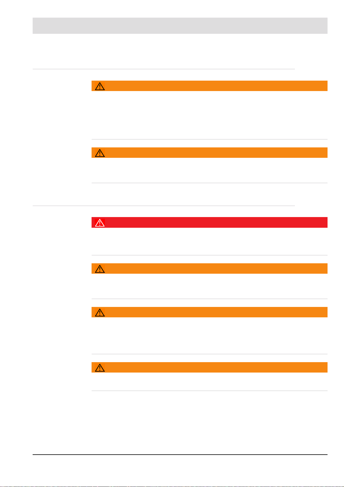
3.1 Structure of the F300K
1 Lens holder
2 F300K housing
3 Cover with operating unit
UI (user interface) or
LED display
4 Device connector
5 Connecting cable
Fig. 3-1 The components of the F300K
9
Page 11
3 Product Description
3.2 Basic variants
There are two basic variants of the F300K
NOTICE
The basic functions of the variants are identical. The differences lie merely in how they are
operated and their displays.
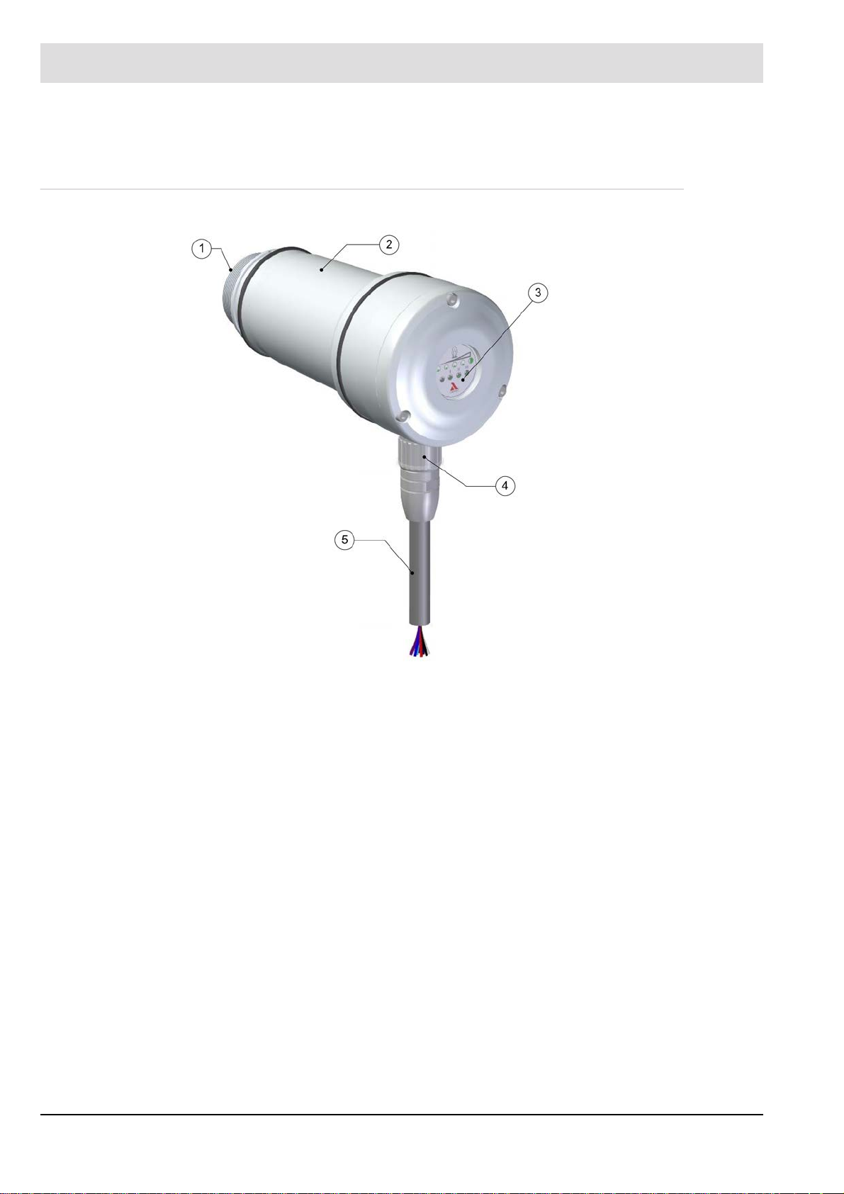
F300K with LED display
Fig. 3-2 F300K display unit with LED display
1 LEDs in the display strip show the intensity of the flame: a series of two yellow and three
green LEDs; point display for intensity, flashing for a warning
2 Green LED: mode 3
3 Green LED: mode 2
4 Green LED: mode 1
5 Red LED: Flame OFF/stand-by – flashes in the event of a fault
NOTICE
For operation of F300K (with LED display) you need an external User Interface UI or the
F300K Remote Software.
10
Page 12
3 Product Description
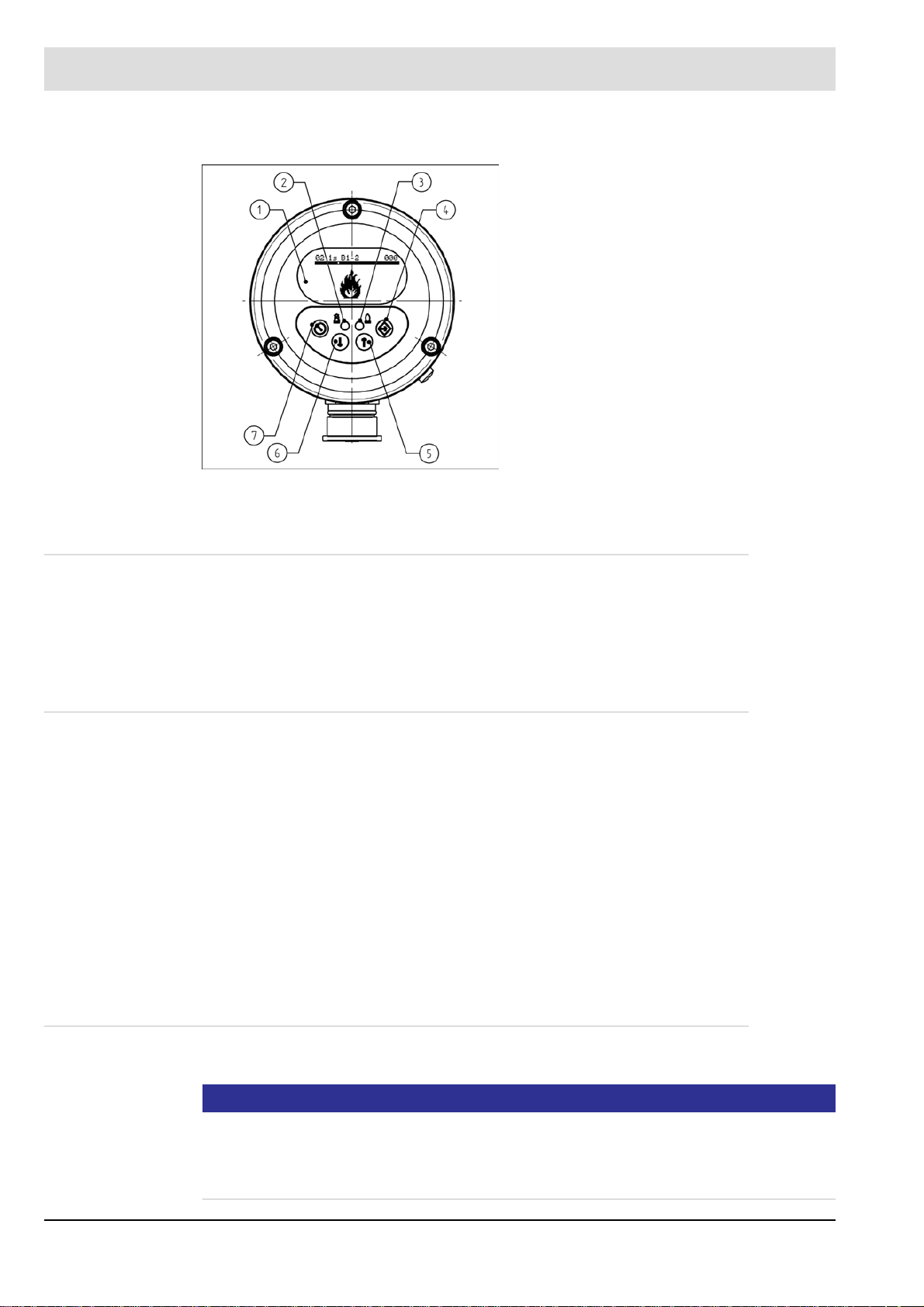
F300K with user interface
Fig. 3-3 F300K operating and display unit with UI
1 Display
2 LED shines red: Flame OFF/ready for
operation
LED flashes red: fault
3 LED shines green: flame ON
LED flashes green: warning
4 ENTER key
5 UP key
6 DOWN key
7 ESC/BACK key
3.3 Life Cycle
The device is designed to have a service life of 10 years or 250,000 cycles. The functional
safety calculations are based on these values.
The actual service life of the F300K depends on the ambient temperature among other factors.
In particular, operation at high temperatures reduces the actual service life.
3.4 Proper Use - Conditions of Use
The F300K is designed to monitor the safety of burner flames in single- and multi-burner combustion plants and in combustion chambers for dust- and grate-fired systems.
As an explosion-proof device, the flame scanner can be used in potentially explosive atmospheres (up to Zone 2).
Any other usage going beyond this is considered to be improper use. The plant operating company is liable for any damages that resulting from this.
The table in Section 3.6 Selection Criteriashows the applications to which the various device
types are suited.
Please heed the following information when operating the F300K:
• The safety information in this manual
• Section 14.1 Technical Data in this manual
3.4.1 UL Listed
In preparation
NOTICE
For applications within the scope of the UL Listed certification procedure, it must be ensured
that the components used are "Listed" certified. That is, in addition to the flame detector used
must also be the connection cable and if used the power supply "Listed" certified.
The applicable installation rules according to NFPA70 (NEC) must be observed.
11
Page 13
3 Product Description
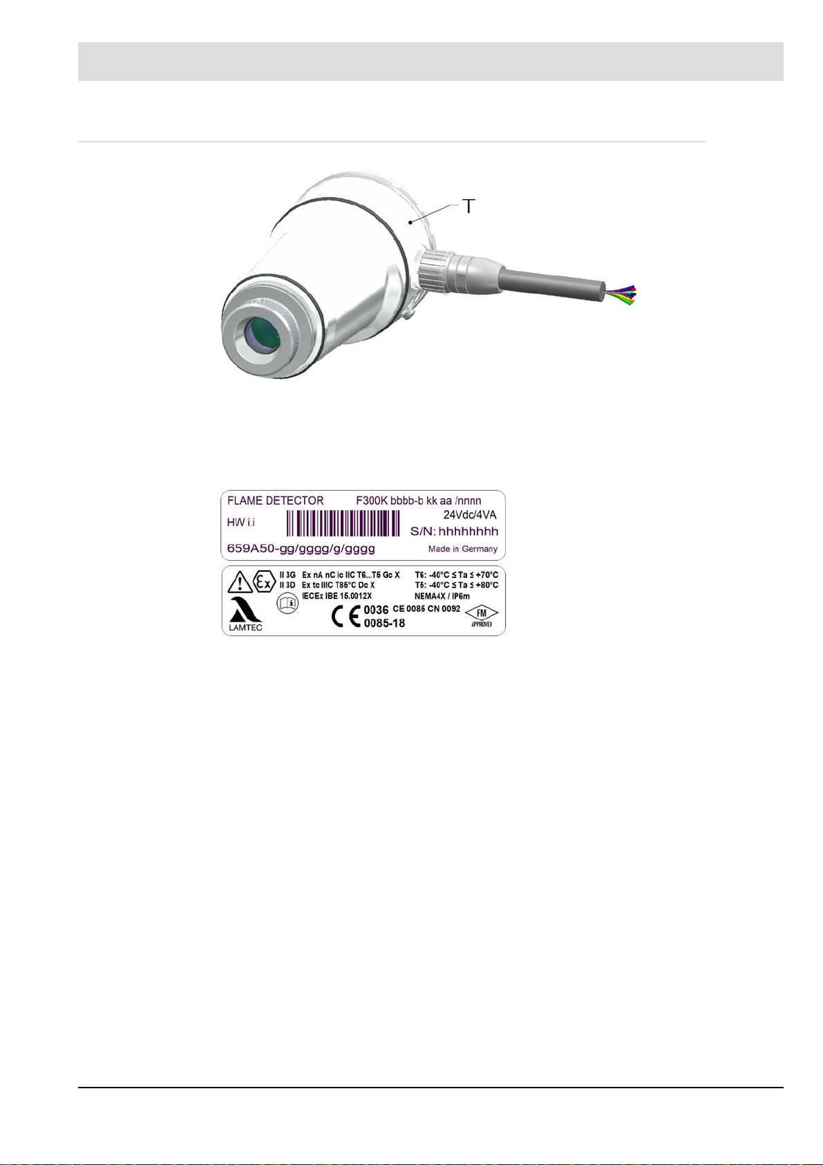
3.5 Rating Plate
Fig. 3-4 Position of the rating plate
T = position of the type plate
On the rating plate you will find information on the configuration of your flame sensor:
Rating plate example:
12
Page 14

3 Product Description
3.6 Selection Criteria
The spectral sensitivity of the flame scanners determines their suitability for specific fuels.
NOTICE
LAMTEC guarantees that the flame sensor is in perfect working order but cannot offer any
guarantees if it is used improperly.
Note the specific requirements of your plant when selecting the flame sensors. We will be
pleased to answer any questions you may have in relation to LAMTEC products.
The following table provides an overview:
Type Fiber
Optic
F300K UV-4 X ++ 215 ... 360 8° • Oil
F300K UV-4.6
F300K IR-2 * ++ 850 … 1200 • Combustion chamber monitoring
F300K IR-3 * ++ 1000 … 1700 60° • Oil-, gas-, wood-, coal- and dust-fired
F300K IR-4
F300K UVIR-1
X
*
X
*in preparation, use may only be made with LAMTEC IR fiber optic system
The suitability of the device types may differ from that indicated in the table depending on particular circumstances.
Sensi
tivity
+++
+++
++ 215 ... 360
Spectral
range
in nm
215 ... 360
1000 ... 2200
Sight
angle
approx
10°
60°
8°
Preferred area of application/fuels
• Gas
• Special gases such as refi nery gases,
blast furnace gases and hydrogen
furnaces with a high level of flue-gas
recirculation
• Yellowish waste gases without UV radiation or with shielding of the UV spectrum by water vapour and dust
• as F300K UV-4
• as F300K IR-3(double sensor) ++ 1000 ... 1700
Fig. 3-5 Spectrum of the flame
13
Page 15
3 Product Description
3.7 Accessories
NOTICE
When installing electrical accessories you must ensure that the necessary protection class is
reached.
3.7.1 FB30 External User Interface
The FB30 external operating unit offers the same range of functionality as the internal UI built
into the F300K. It can be used with an F300K (without an integrated operating unit) or a F300K
UI (with an integrated operating unit).
Y ou can connect the FB30 directly to the FG30 connection housing using its plug-in connector .
The FB30 is then supplied with 24 VDC from the power supply of the F300K.
You will find the technical specifications for this device in section 14.1.2 FB30 External User
Interface.
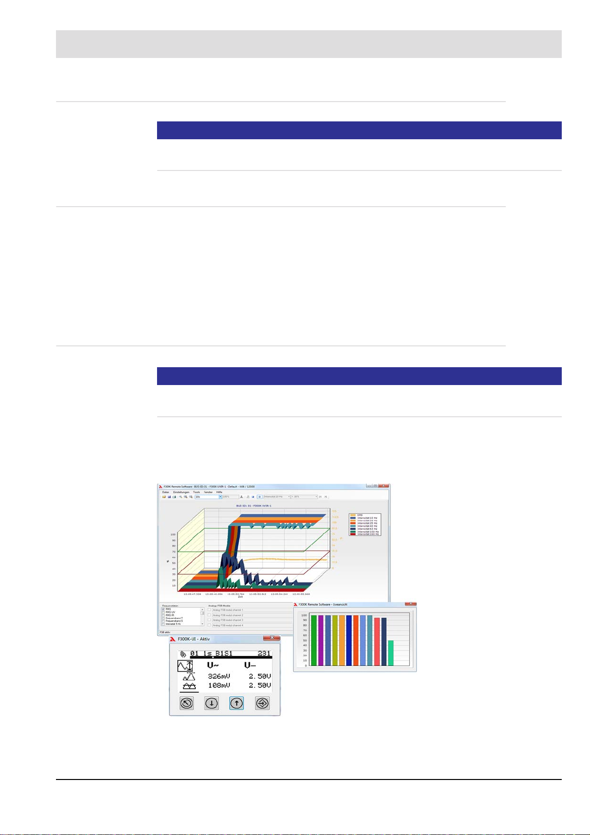
3.7.2 F300K Remote Software
NOTICE
LAMTEC provides a CAN/USB adapter with the F300K Remote Software. You can use this
with a specific adapter cable to connect your PC to the CAN bus of the F300K.
The F300K Remote Software allows you to do all the parameterisation of an F300K. In addition, it also offers analysis, data backup and recording functions.
In addition to the data of the F300K, you can also record external, analogue and/or digital data
by means of CAN modules. All of the data is synchronised.
Fig. 3-6 Remote PC software
You will find further information in a separate description F300K-Remote-Software
(DLT-No. 7652).
14
Page 16
3 Product Description
3.7.3 Power Supply
3.7.3.1 Power Supplies
Y ou can use a commercially available power supply with an output voltage of 24 V that meets
the protective separation requirements. See section 6.1.2 Electrical Safety – Requirements to
Be Met by Third-party Manufacturers.
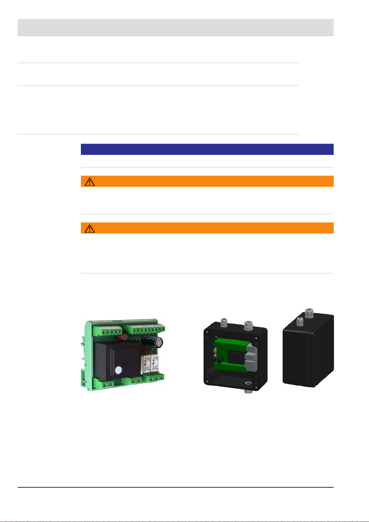
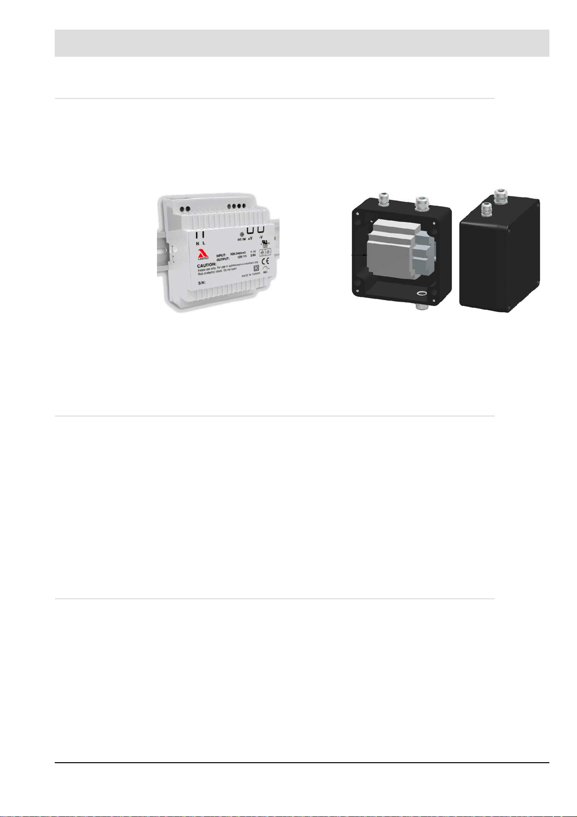
3.7.3.2 FN20, FN30-20 Power Supply
NOTICE
The FN20 (115 V) is UL Listed approofed.
WARNING!
Instalation
The wires must be installed/attached in such a way that, if a wire is unintentionally loosened,
a sufficient distance is still maintained between SELV/PELV and the other voltages.
WARNING!
Secure output contact and secure indicator contact
Danger due to electric shock! This may result in personnel injury.
Basic insulation is used for protective separation, i.e. you may not use SEL V (safety extra
low voltage) and mains voltage at both of the contacts at the same time.
You can use the FN20 power supply to operate the F300K at mains AC voltage. The power
supply is designed for top-hat rail mounting (for F300K can be supplied as an option with built
in an IP65 housing).
Fig. 3-7 FN20 for top-hat rail mounting
Fig. 3-8 FN20 as a built-in unit
The power supply is equipped with safety output relays (to EN 298) for mains AC voltage. The
power supply complies with SIL 2 (Safety Integrity Level) to EN 61508.
When you connect the F300K to the FN20 power supply, you do not connect all of the wires
of the connecting cable to the terminals. You have to connect the surplus wires to separate
terminals. These terminals are part of the F300K's IP65 housing.
Y ou will find the technical specifications for this power supply in section 14.1.3.1 FN20, FN30-
20 Power Supply.
15
Page 17
3 Product Description
3.7.3.3 FN30 power supply
The power supply unit FN30 can only be used to operate the F300K on an AC mains voltage
within the scope of EN 60950 or UL 60950.
The power supply is available in two versions:
• For top-hat rail mounting
• As a built-in unit in a housing
Fig. 3-9 FN30-00 top-hat rail mounting
When connecting the F300K to the FN30-00 power supply , not all wires of the connection cable are connected to the power supply connections. Surplus wires must be connected to separate terminals. These terminals are part of the housing.
Technical data for this power supply unit can be found in section 14.1 Technical Data.
3.7.4 Coupling relays
To connect the contact outputs of the F300K to voltages higher than 42 V or voltages without
protective separation, you have to use coupling relays. These must met the protective separation requirements. See section 6.1.2 Electrical Safety – Requirements to Be Met by Third-
party Manufacturers.
In addition, you also require appropriate certification for the coupling relay with a safety contact output (flame signal) for the purpose for which it is to be used (e.g. to EN 298 and/or to
EN 61508 with SIL III or SIL II).
The LAMTEC FN20 and FN30-20 power supply has coupling relays for the flame signal.
These meet EN 298 und EN 61508-2 SIL 2 requirements.
If you want suitable coupling relays or have any questions, please contact our support staff at
vertrieb@lamtec.de or on +49 (0) 6227 6052-33.
3.7.5 Adjustable Holder, Cooling-air Housings
Fig. 3-10 FN30-10 as a built-in unit
You will find a complete overview of the holders and cooling-air housings for LAMTEC flame
scanners in the document "Flame Monitoring Systems and Accessories" (DLT7673).
16
Page 18

3 Product Description
3.7.6 FG30 connection housing
Regard the applicable rules and regulations for mounting and installation, note also the additional requirements described in section 6.1.1 Safety When Putting the Device Into Operation
Fig. 3-11 FG30-00 connection housing
LAMTEC offers two versions of the FG30 connection housing:
• FG30-00 with cable glands and an M12 circular connector for FSB
• FG30-20 Ex-II for use in potentially explosive atmospheres with cable glands and an M12
circular connector for FSB
Y ou will find technical specifications for the housings in section 14.1.4 FG30 connection hous-
ing and FG30-21 stainless steel.
Fig. 3-12 FG30-20 Ex-II connection housing
17
Page 19

3 Product Description
3.7.7 Flame Scanner Testing Device
Fig. 3-13 Toggle switch UV/IR
Fig. 3-15 Positions of the internal jumper UV + IR
You can use the FFP30 to test that your flame scanner is working properly.
The testing device simulates a variable flame frequency.
If the internal jumper(1) is plugged on IR, UV or IR can be chosen via the toggle switch.
If the internal jumper is plugged on IR+UV, the switch position IR as well as UV rays can be
detected simultaneously. The latter can be interesting for flame scanner with dual sensor.
Flame scanner testing device is off in the average position of the toggle switch. The flame
scanner testing device switches off automatically after a preset time of approximately 4 min to
reserve the battery resource.
The testing device is screwed onto the flame scanner.
For the recognition of the flame simulation, the F300K must be set to sufficiently sensitive (increase, trigger threshold and frequency).
To change the battery, see chapter 8.1.1 Flame Scanner Testing Device replace Battery
Fig. 3-14 FFP30 flame-scanner testing device
WARNING!
After a possibly necessary modification of the F300K setting for the test, the original
settings must be set back and controlled through the CRC manual of the operating
mode parameter.
DANGER!
Explosion hazard!
Flame sensors must not be tested in a potentially explosive atmosphere.
You will find the technical specifications for this device in section Fig. 14-27 Dimensioned
drawing of the FB30.
18
Page 20
3 Product Description
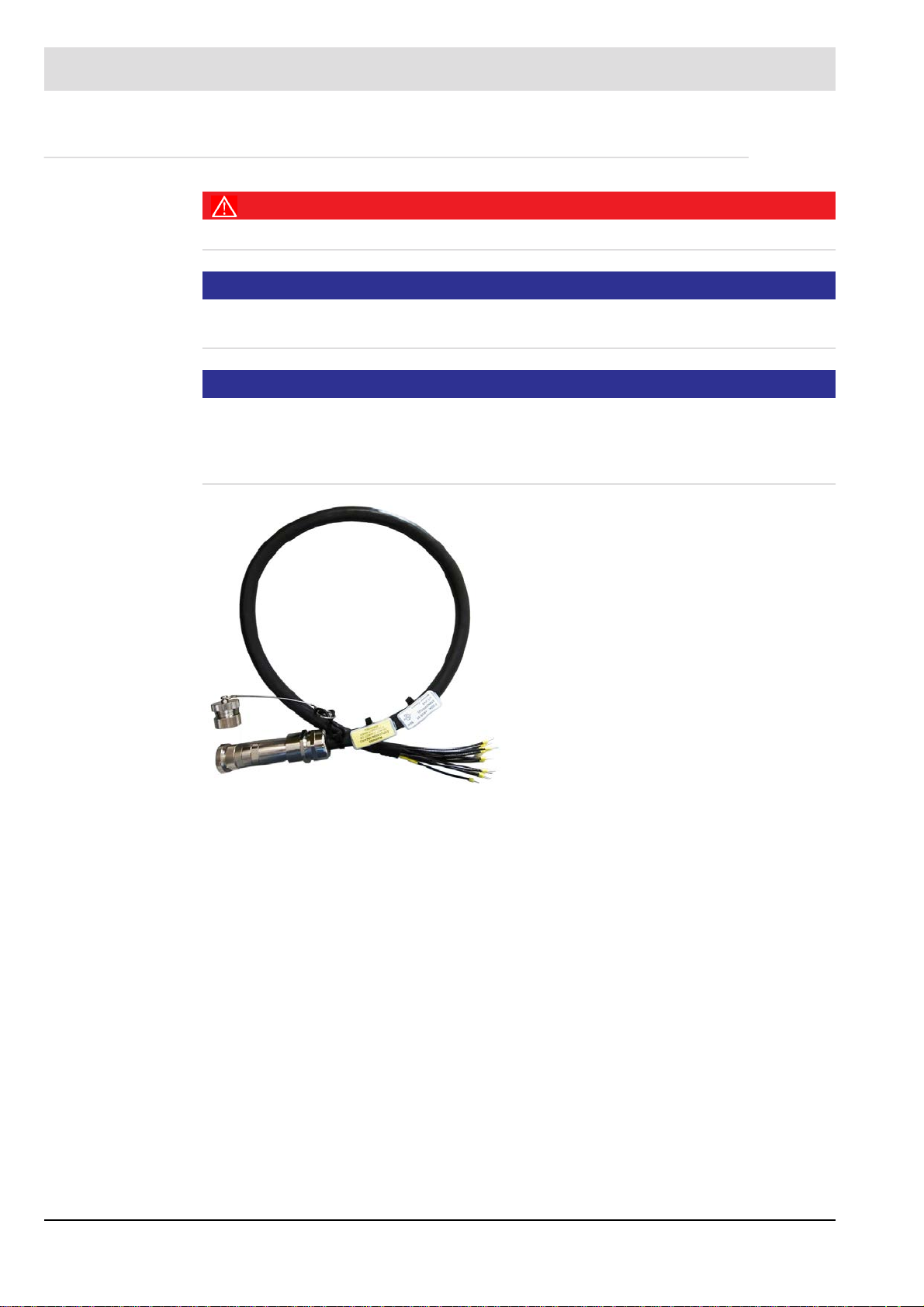
3.7.8 Connection Cable AK05
DANGER!
The Connection Cable are approved for use with SELV or PELV only.
NOTICE
For special requirements it may be necessary to protect cable additionally.
The specific installation rules are to be observed.
NOTICE
Only the Connection Cable AK05-51 is UL Listed approofed. For the use of the Flame scanner as UL Recognized approofed, the other Connection Cable can be used.
Devices shall be wired in accordance with NEC field wiring requirements for the
location.
Fig. 3-16 Connection Cable AK05-51
19
Page 21

3 Product Description
3.7.9 Fiber Optic
The LAMTEC Fiber Optic System is available with 2 spectral sensitivities and 2 basic
mechanical constructions.The spectral sensitivity is matched to the LAMTEC flame detector.
WARNING!
F300K IR-x FO
The flame detector F300K FO in the IR version (IR-2..4) may only be used with the
LAMTEC Fiber Optic in the IR version. The Fiber Optic IR version includes the required
spectral sensitivity limitation.
Visible is the Fiber Optic IR version on the process optics (see Fig. below).
The viewing port to the flame is not a lens, but covered with a black filter.
Fig. 3-17 Fiber optic with Flame scanner
1 Component Group Process Optics 3 Component Group rigid housing
1.1 Optic UV 4 Component Group burner mounting assembly
1.2 Optic IR 5 Component Group Flamescanner holder
assembly FV30-FO
2 Fiber bundle (customer-specific length)
Fiber Optic with enclosure - Type key: FOabb-cc-dd
a - enclosure type: R - starr, F - flexibel
b - enclosure series: e.g. 10
c - lenght: e.g. 25 - (2,5 m)
d - optic: UV - uv/vis/nir, IR - nir
20
Page 22
3 Product Description
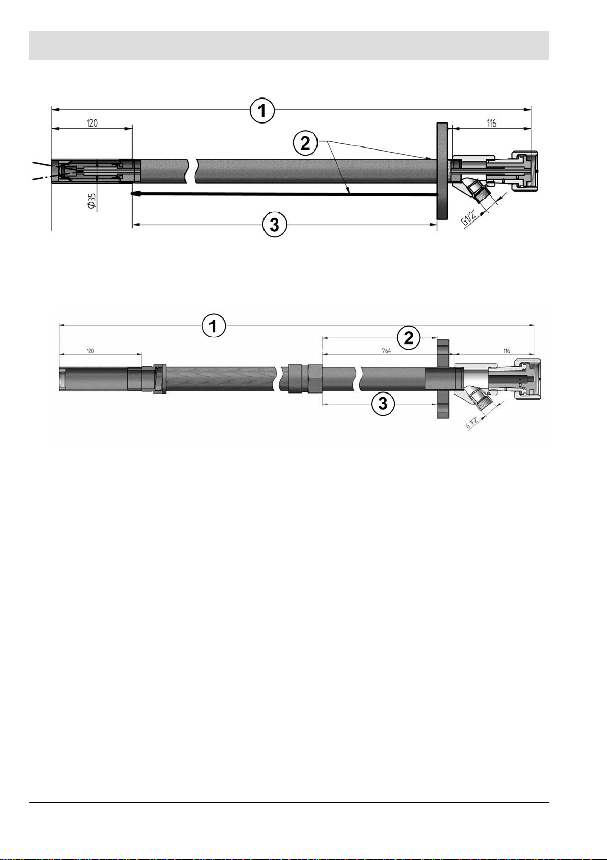
Fig. 3-18 Fiber optic rigid, FOR10-XX-XX
1 Minimum total length 1000 mm / 3,28 ft 3 Adjustment length 740 mm / 2,43 ft
2 Mounting flange positionable
Fig. 3-19 Fiber optic flexible, FOF10-XX-XX, in preparation
1 Minimum total length 1500 mm / 4,92 ft
21
Page 23

4 Design and Functions
4 Design and Functions
4.1 Design
Structure:
The compact flame scanner consists of a cylindrical housing with an axial aperture and an
LED status display at the back or an integrated operating unit with an UI (user interface).
Connection:
The connection is made via the serial connector on the F300K and the required connecting
cable (14-pin with static shielding) with coupling.
The cable offers the following connections:
• Supply of auxiliary power
• Flame contact
• Ready contact
• Measuring output for intensity
• FSB (Bus)
• Shield
22
Page 24
4 Design and Functions
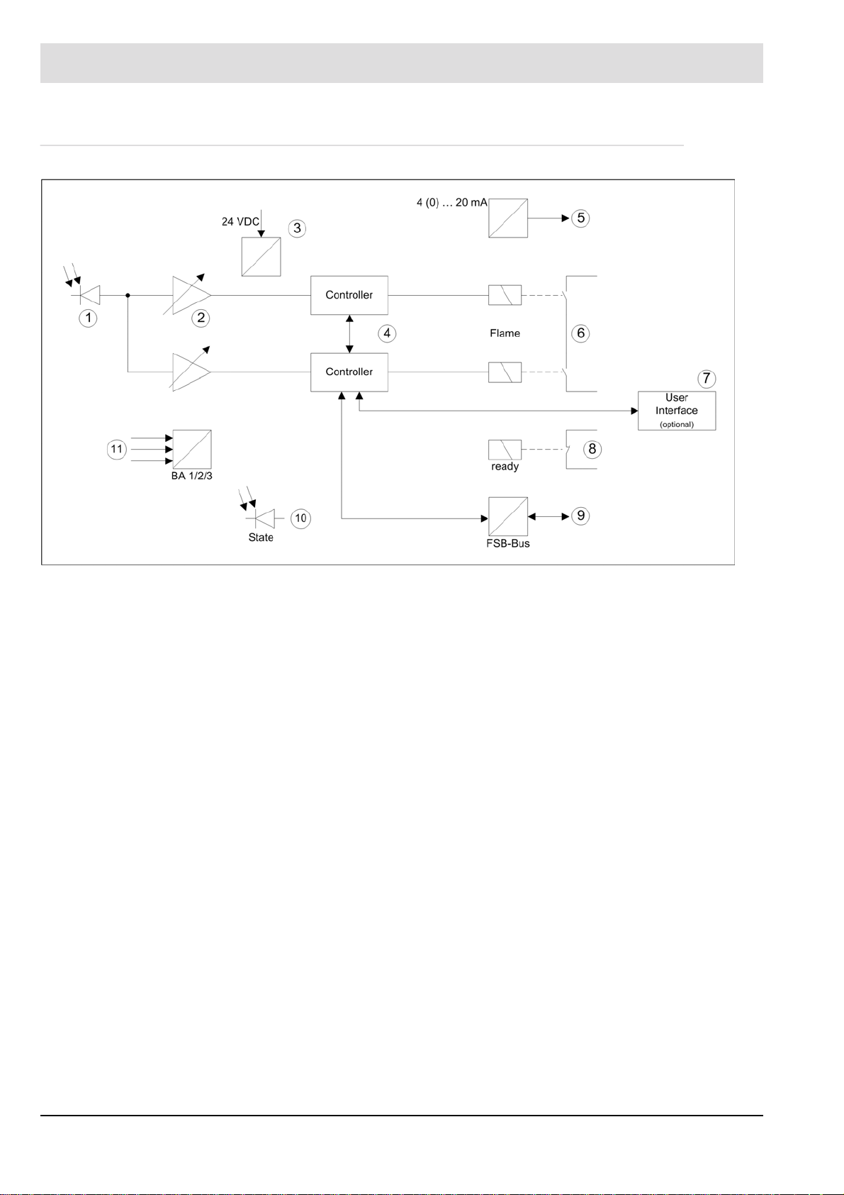
4.2 Functional Description
1 Semiconductor sensor 5 Measuring output for intensity 9 FSB bus for parameterisation and mes-
sages
2 Amplifiers 6 Flame relay 10 LED status display
3 Power supply 7 Integrated operating unit (UI) 11 Mode selector
4 Microcontrollers 8 Ready
The F300K analyses the flickering of the flame in the UV or IR range. For preparation for signal
processing there is a semiconductor sensor (1) on a button strip. For each sensor signal,
the level is adjusted by means of two adjustable amplifiers (2). These two amplifiers are located on the main board, as are the two microcontrollers (4). Due to the amplitude and the
course taken by the signal to be evaluated over time, both microcontrollers detect the existence of the flame.
The safety of the device is monitored by means of both software and hardware diagnostics.
The ready contact (8) indicates that the flame scanner is ready for operation.
The mode selector (11) allows you to choose between three different sets of parameters.
These parameters are stored in the EEPROM and influence the analysis of the current sensor
signal of the flame to be monitored.
There is a FSB interface (9) available for operation. The F300K is operated by means of an
external or internal user interface (7) or the PC with F300K-Remote-Software. An LED dis-
play (10) makes the status of the flame scanner visible. The flame intensity is provided as
non-failsafe information with a 4 (0) ... 20 mA current loop (5).
The circuit is supplied with 24 VDC (3) by an external power supply unit with safe separation
(e.g. FN20 or FN30).
An internal temperature sensor monitors the temperature in the device.
23
Page 25
5 User Interface
5 User Interface
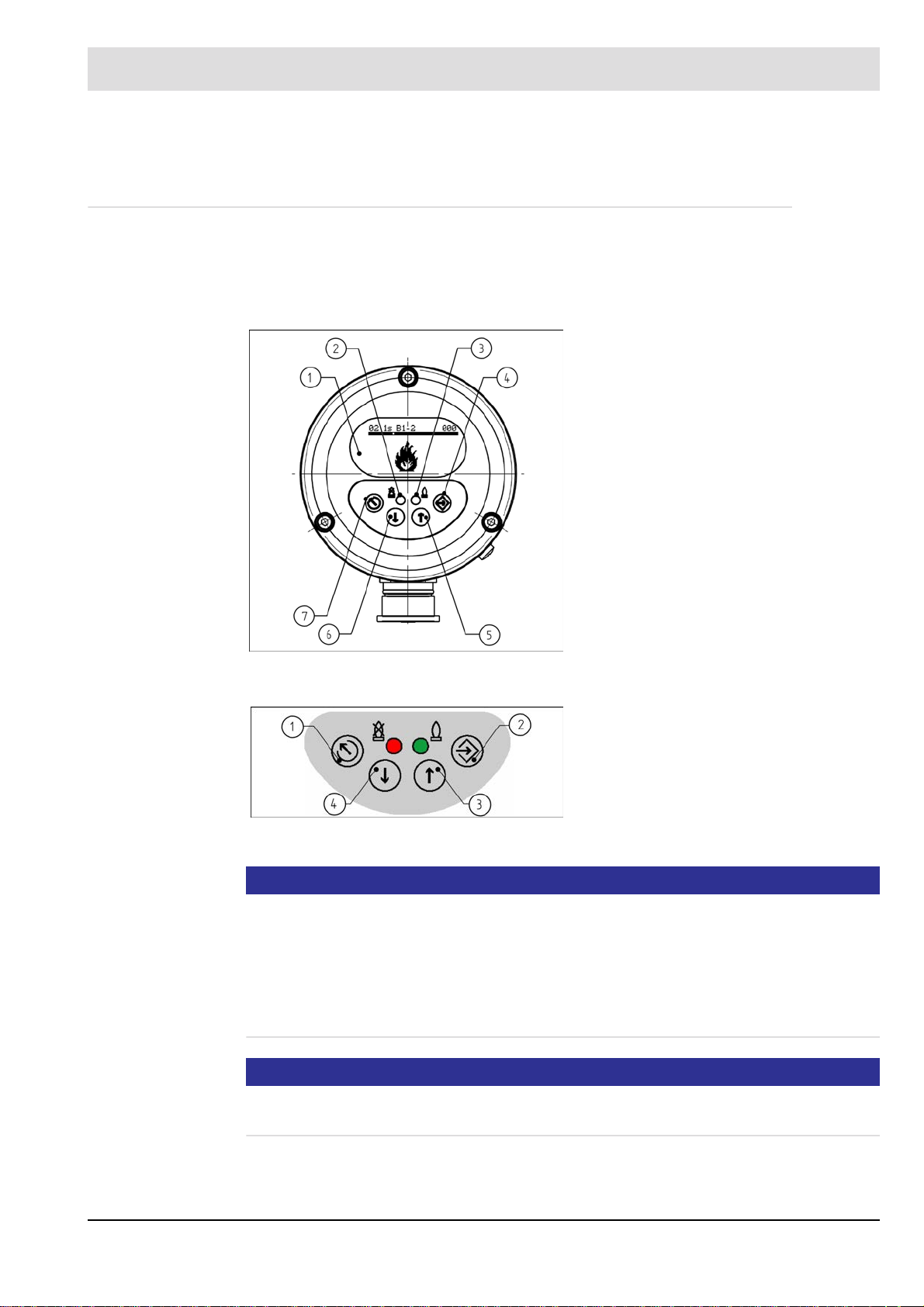
5.1 Operating and display elements
You can adjust and operate the F300K compact flame scanner by using either the user interface (integrated in the F300K or as an external device) or the F300K Remote Software.
You will find a description of the F300K Remote Software in a separate manual (publication
no. DLT7652).
1 Display
2 LED shines red: Flame OFF/ready for
operation
LED flashes red: fault
3 LED shines green: flame ON
LED flashes green: warning
4 ENTER key
5 UP key
6 DOWN key
7 ESC/BACK key
Fig. 5-1 F300K operating and display unit with UI
1 ESC/BACK key
2 ENTER key
3 UP key
4 DOWN key
Fig. 5-2 Keypad
NOTICE
To extend the service life of the display, it only remains switched on within a limited temperature range. If the temperature of the display rises to over 70 °C, it is deactivated. In this phase
it is not possible to carry out parameterisation or read out information using the display . In order to get information about the reason (C0013) of the deactivated display , it is activated briefly after pressing a key.. If the temperature of the display drops below 70 °C, it is activated
again. Alternatively, the F300K Remote Software or an external user interface FB30 can be
used to communicate with the F300K from a cooler place.
NOTICE
The accessibility and operation of the different displays depend on the current access level.
See section 7.2 Enter Password.
24
Page 26

5 User Interface
5.2 Menu tree
25
Page 27

6 Commissioning
6 Commissioning
6.1 Safety
6.1.1 Safety When Putting the Device Into Operation
DANGER!
Danger if shock protection is not provided
There is a risk of death or very serious injury from electric shock.
When installing the electrical accessories, do everything necessary to provide shock pro-
tection.
Y ou must comply with the requirements of protection class IP40 or IP54 (for use outdoors)
to EN 60529.
WARNING!
The fiber optic flame detector versions F300K.. IR-.. FO with IR sensors may only be used with
the LAMTEC IR Fiber optic FOR...-IR or FOF...-IR.
NOTICE
Exceeding the maximum permissible operating temperature
Ensure that the maximum permissible operating temperature (see the table in Section 14.1
Technical Data) is not exceeded at the installation location, in particular as a result of radiant
heat.
Take action to ensure sufficient cooling.
LAMTEC offers the FK30 cooling air housing.
NOTICE
Laying of cables
Warning to avoid damage to property
The cables are designed for a special temperature range see chapter 14.1 Technical Data
Lay the connecting cable including its extension apart from the mains and control cables
(don't lay them parallel to each other).
Avoid laying cables near the following components:
- Ignition cables
- Ignition transformers and electric motors
- Contactors or switches and frequency converters that switch high inductive or capacitive
loads
Although the device exceeds the requirements of the applicable EMC standards, in some
cases by a considerable amount, proper wiring is the prerequisite for ensuring that the device and thus the entire plant operates without problems in all cases.
26
Page 28

6 Commissioning
NOTICE
Shielding/extension of connecting cables
Warning to avoid damage to property
Apply shielded cables directly (without any intermediate terminals if at all possible).
If intermediate terminals are necessary, take the shortest route to applying the shielding
to the terminal.
Avoid long connecting wires without shielding.
Use a separate, shielded extension cable to implement an extension on site.
NOTICE
High electromagnetic interference
Excessive electromagnetic interference can lead to sporadic problems with flame detection
and even prevent it.
Connect chassis earth (earthing bolt at the device) to functional earth (FPE).
It is a connection between the mass of the supply voltage and FPE prepared.
NOTICE
EMC emission testing
It was ascertained during the type test that the device meets the EMC emissions requirements. A separate EMC emissions test is not necessary after installation.
27
Page 29

6 Commissioning
6.1.2 Electrical Safety – Requirements to Be Met by Third-party Manufacturers
DANGER!
Supply voltage
The device's supply voltage may only be generated by means of a safety power supply unit of
a different make from the one described in the accessories if safety extra-low voltage is used
(e.g. to EN 61558-2-6 "Safety of transformers" or EN 60950-1 "Information technology equipment – Safety".
DANGER!
"Flame signal" and "ready" relay contact outputs
The potential-free contact connections of the device's relays may only be wired with safety extra-low voltage in accordance with the requirements for supply voltage.
DANGER!
"Mode selector" digital inputs
The digital inputs are controlled only via potential-free contacts.
DANGER!
Communication interfaces
The equipment of other manufacturers connected to the communication interfaces must meet
the requirements of DIN EN 60950-1 "Information technology equipment – Safety".
DANGER!
Analogue output current loop - Protection against electric shock
Measuring circuits must be separated safely to dangerous active parts according to EN 61 140
„Protection against electric shock …“.
You achieve this by double or reinforced isolation according to EN 61010-1 „Safety re-
quirements for electrical equipment for measurement, control and laboratory use“.
WARNING!
Radio interference suppression of the output contacts
In the interests of safety, ensure when installing the output contacts that:
The user suppresses radio interference in such a way that the contacts of the safety relay
contact output cannot be shorted by defective components of the suppressor circuitry.
28
Page 30

6 Commissioning
6.1.3 Special Points to Note When Using the Device in Explosion-proof Areas
The following applies when using the F300K in explosion-proof areas:
• For use only in approved explosion protection zones.
• T o protect its aperture, only mount the F300K on a burner or boiler using one of its holders:
the FV30, FV40, FK41 or FK46.
• Use only the types of cable specified by the manufacturer when extending cables.
• When extending cables in the potentially explosive area, use only terminal housings that
are approved for this area. LAMTEC recommends the connection housing FG30-20 Ex II
for this purpose.
• Check if cable connections fit tightly. Should there be a need to loosen the cable connection, it is to be ensured that the cables do not turn while loosening and tightening the cable
connection.
• Note, in particular, the information on setup in EN 60079-14, section 12.2 (cables and
earthing).
• Only remove the connector of the F300K or FB30 Ex or any other cable connections when
it is deenergised.
See the warning on the device: WARNING – DO NOT DISCONNECT WHEN ENERGISED.
• In particular, seperation has to be in accordance with EN 60079-14 'Appendix: Instructions
for procedures to work safely in an explosive gas atmosphere', only permitted after the release by personnel in charge of the explosion protection of the operating company.
• The F300K and FB30 may only be opened by the manufacturer or authorized personnel.
It is not necessary to open the device when putting it into operation.
• A transformer for generating the supply voltage must be carried out according to
IEC 61558-2-6.
• You must use a current limiter with a limit on the rated voltage.
• When using the device in the ambient temperature range, you must keep the temperature
in accordance with the temperature class: See Ex marking on the device
• If devices are so damaged that they no longer meet the requirements of the IP64 protection class, you must replace them.
Special instructions for use in Hazardous Area Class I Division 2 (valid for F300K)
• Devices shall be wired in accordance with NEC (National Electrical Code) field wiring
requirements for the location.
UL Listed Version:
• The plug of the connecting cable must be secured against self-loosening after mounting
on the flame detector. There are screws on the union nut of the connector.
29
Page 31

6 Commissioning
Marking information on the device: Example
F300K/F300K UI FB30
Warning: e.g.
30
Page 32

6 Commissioning
6.2 Installation
The following sections provide information on:
• What prerequisites have to be met to install the product properly
• How you have to position the product
• How you have to secure the product
6.2.1 Prerequisite for Mounting the Device Properly
NOTICE
Mounting the device using a holder
If at all possible, mount the flame scanner to the burner/boiler using a holder optimised by
LAMTEC for use with flame scanners. Characteristics see chapter 6.1.3 Special Points to
Note When Using the Device in Explosion-proof Areas
If you do not do this, ensure that the device is insulated in order to prevent any interference
from equalising currents (via the cable shield).
NOTICE
Mounting location
Ensure that the mounting location is easily accessible. During operation of the combustion
plant, you should be able to see the optical monitoring elements well.
WARNING!
The fiber optic flame detector versions F300K.. IR-.. FO with IR sensors may only be used with
the LAMTEC IR Fiber optic FOR...-IR or FOF...-IR.
31
Page 33

6 Commissioning
6.2.2 Positioning
The processes that take place in combustion result in pulsing radiation (flickering of the flame).
The series of oscillations (flame frequency) involved are used for monitoring purposes.
Position the aperture used for selective monitoring in such a way that the compact flame
scanner/flame sensor picks up the root of the burner flame to be monitored (near the
mouth of the burner).
NOTICE
The burner flame must be well visible throughout the combustion plant's operating range.
Ensure that the compact flame scanner/flame sensor does not point directly at flame that
is opposite or adjacent.
This is also very important when it comes to background flames (e.g. coal, wood, waste).
1. Mount the compact flame scanner/flame sensor on the burner's viewing opening. Use the
corresponding adjustable holder for this.
The compact flame scanner/flame sensor is now mounted. Pay attention to the following
instructions for alignment.
WARNING!
Overheating of the flame sensor / flame scanner
Ensure that the max. permissible ambient temperature is not exceeded at the installation site.
Due to the location where the flame scanner is installed, increased temperature can occur on
the scanner, especially with the FFS08.
The operating mode of the burner or appropriate cooling measures must prevent the per-
mitted operating temperature from being exceeded.
If the permissible operating temperature has been exceeded, the flame scanner or flame
sensor must be replaced.
Measures must be taken to prevent such a situation.
An overheated flame sensor or flame scanner is operated outside its specification.
As a result, it is possible that the safety function is no longer active.
32
Page 34

6 Commissioning
6.2.3 Alignment
NOTICE
Recommendation
If there is no ball joint available already , we therefore recommend using a LAMTEC adjustable
holder with the FV40-10 ball joint. The viewing direction of the flame detector must cut the
flame (see figure 6-1).
Particularly when there is an additional sight tube in the burner or the view of the flame is
considerably restricted, it is very important to align the flame scanner to optimum effect.
The longer the sight tube, the more advantageous it is that it has a larger cross-section.
NOTICE
Alignment parallel to the axis
In the axially parallel arrangement, it can be difficult to detect that the flame has gone out.
Avoid aligning the F300K in an axially parallel arrangement with the flame.
The correct positioning (alignment) of the F300K is a decisive prerequisite for high availability
or for the achievable selection quality. In any case, you should always take into account that
the aperture in the UV and UVIR (double sensor) versions is very restricted due to the lens.
Align the compact flame scanner as follows:
• Align the F300K preferably in such a way that it picks up the first third of the flame to be
monitored (high flame frequencies).
• Also align the F300K in such a way that it picks up only a small part or, even better, none
of the radiation from other burners or the re-radiation from the combustion chamber (low
flame frequencies).
Fig. 6-1 Pulsing of the flame radiation – frequency
33
Page 35

6 Commissioning
6.3 Electrical Connection
NOTICE
It is not required to change to the respective mains frequency.
Periodic signals> 47 Hz are recognised for safety reasons as disorder. This covers the requirements of standards for insensibility in the range of mains frequency (50/60 Hz) and their
multiples. Therefore it is not necessary to change the mains frequency on site.
You will find connection diagrams in the Appendix, Section 14.2 Connection Diagram
6.4 Putting the Device into Operation for the First Time
6.4.1 Requirements
Prerequisites for putting the device into operation for the first time:
• The F300K must be mounted as specified in Section 6.2 Installation.
• The F300K must be aligned as specified in Section 6.2.3 Alignment.
• All electrical installations must have been tested.
• All terminal and plug-in connections must have been tested.
6.4.2 Parameter
NOTICE
Putting the device into operation
To operate the F300K safely, you have to adhere to the following sequence when putting
it into operation for the first time:
1 Release access level 1 or 2 by means of a password: Section 7.2 Enter Password.
2 Set the flame parameters of the F300K: Section 6.4.4 Setting Monitoring Parameters.
3 Set the monitoring parameters of the F300K: Section 6.4.4 Setting Monitoring Parame-
ters.
4 Check the setting of the parameters by means of the switch-off test: Section 6.4.5 Switch-
off Test.
During operation it is possible to change parameters. Parameters have a well-defined 2-digit
numbering and in most cases they are characterised by a symbol.
There are different sorts of parameters:
• Operating mode parameters for the behaviour of flame detections
• Device parameters of the flame scanner (p.ex. BUS-ID or current loop)
• Device parameters of the User Interface (p.ex. light ON time)
34
Page 36

6 Commissioning
6.4.3 Adjusting F300K
Checking the switch-off parameters
There is a risk of death and serious injury.
The switch-off parameters are to be verified through switch-off tests, see chapter 6.4.5
Switch-off Test. Changes made to settings (increase or weighting of doublesensor) do af-
fect the switcht-off parameters and therefore new switch-off tests are to be carried out.
NOTICE
Reliable detection of the flame
Warning to avoid damage to property
Set the parameters in such a way that, across the entire performance range and in all of
the combustion's modes, safe detection of "flame OFF" and stable detection of "flame ON"
are ensured.
WARNING!
NOTICE
Aligning and setting the parameters of the flame scanner
Warning to avoid damage to property
Right from the outset, you must align the flame scanner to optimum effect and optimise its
settings. Any changes alter aspects of how the flame scanner works. Following any
change, it is necessary to check the correct switch-off parameters again by means of corresponding switch-off tests.
You generally start making settings with the flame burning at the burner's base firing-
rate and can then continue for the background signal when the burner to be monitored is
off. It is also possible to do this the other way around.
NOTICE
Note about some basic prerequisites
Y ou must have selected a mode (see the connection diagrams for hardware control). You
generally start with mode 1.
In the delivery state, mode of operation 2 and 3 are occupied with parameters, and in com-
parison to mode of operation 1, they are more insensitive with regards to flame recognition. Should you wish to use mode of operation 2 or 3, you should proceed like mode of
operation 1.
Should you wish to reset the manufacturer's factory settings, you can load that in the cur-
rent mode of operation (see section 7.6.3 Resetting the device parameter factory settings)
NOTICE
You will find a description of the error messages in section 10 Correcting Faults.
35
Page 37

6 Commissioning
Aligning the F300K
Y ou generally start making settings with the flame burning at the burner's base firing-
rate and can then continue for the background signal when the burner to be monitored is
off. It is also possible to do this the other way around.
Aligning the F300K
1. Open the automatically > Align menu.
Fig. 6-2 Open the Parameterize automatically
If there is no sufficient UV signal available in the usage of F300K UVIR-1 (double sensor)
despite the signal reinforcement to level 13, select 'Adjust the Reinforcement Menu
of the IR sensor.
2. Align the F300K mechanically in such a way that the flame to be monitored reaches the
maximum signal strength.
3. During alignment you can read/check the value from the display of the dynamic range.
Fig. 6-3 "Alignment" menu
for the single sensor version
Fig. 6-4 "Aligning UV" menu for the dual sensor
version
1 Current peak value of the signal
2 Minimum and maximum of the optimum
dynamic range
3 Amplification level of the signal
36
Page 38

6 Commissioning
Amplification setting of the F300K
1. In the Align menu you need to adjust the amplification in such a way that the signal is within the optimum amplitude modulation of the amplitude bar (min - max).
a) Press the key to open the "Amplification setting- Ascending steps" menu.
b) Press the key to open the "Amplification setting - Descending steps" menu.
NOTICE
The amplification setting is only possible step by step (1 level). Then you must confirm by
pressing ENTER.
Fig. 6-5 "Amplification setting" menu
2. Press the key to apply the amplification. A countdown of 8 seconds begins. This is
accompanied by flashing. During this countdown, you have to confirm the setting by pressing ENTER. If you do not, an error message appears and the setting is rejected.
Alternatively, use the key to reject the setting.
Fig. 6-6 "Amplification setting" menu after pressing the ENTER key
The F300K is now ideally aligned.
Amplification optimization of the IR sensor in F300K UVIR-1 (double sensor)
Change to the menu and perform the same steps as in the menu .
Fig. 6-7 Menu "Amplification - IR" for the double sensor version
37
Page 39

6 Commissioning
NOTICE
Dual-fuel operation
T wo ranges are marked for dual-fuel operation without mode selection. The fuel with the lower
amplitude remains within the lower range, and the fuel with the higher amplitude uses the entire range.
Monitoring is generally also possible outside the marked ranges, although not ideal.
Icon Name Wert Erklärung
Peak value 0 ... 2500 mV Current peak value of the signal
01
Trigger threshold adaptation
Amplification 1 ... 13 Amplification level of the signal.
Min mark Optimum dynamic range min.
Max1 mark Recommended maximum of the
Marke Max Optimum dynamic range max.
Overload mark Indicates a signal outside the
0 ... 100 mV Information that the trigger
threshold is too low for the
selected Amplification and is
adjusted automatically to the
displayed value (smallest valid).
optimum dynamic range when
monitoring two fuels in the same
mode for the weaker signal (e.g.
for gas).
normal working range.
current trigger
threshold
38
Displays the current trigger
threshold of the flame scanner.
Above in the OFF and down in
the ON state
Page 40

6 Commissioning
Set the Weightings Between UV and IR Signals (Dual Sensor)
Switch to the menu .
Fig. 6-8 Call up the weighting menu
The amplitude bars would be displayed; UV from the menu IR from the menu and the
weighted signals . The percentage value of the amplitude bars gives a relative amount of the
individual signals to the weighted signals.
Fig. 6-9 Weightings Menu
Settings of F300K Weightings
1. In the weightings menu, you can adjust the settings so that the individual signals UV and
IR can be added with the required percentage and be processed further.
a) Control with , to increase the percentage of UV signal to the weighted signal.
b) Control with , to decrease the percentage of UV signal to the weighted signal.
2. Control with to confirm the weightings. A countdown of 8 s starts now. This would be
shown with blinking. During the countdown, you must confirm the settings through ,
otherwise you will get an error message and the settings will not be saved
Alternatively you can discard the process with
WARNING!
The shut-off parameters which are determined by the settings procedure are only valid when
these are verified through corresponding shut-off tests, see chapter6.4.5 Switch-off Test
39
Page 41

6 Commissioning
6.4.4 Setting Monitoring Parameters
6.4.4.1 Automatic setting
This section describes the learning processes for setting the monitoring parameters.
WARNING!
Checking the switch-off parameters
There is a risk of death and serious injury.
The preset switch-off parameters are to be verified through switch-off tests see
Section 6.4.5 Switch-off Test
Recording the signal with the flame ON
Y ou must have aligned the device and set the amplification to optimum effect beforehand.
Select the firing-rate state with the lowest signal amplitude. This is normally the base fir-
ing-rate.
NOTICE
Y ou can open the menus Record flame ON, Record flame OFF and Analyse individually
or process them as a series.
Y ou can also have the monitoring parameters set automatically and/or set them manually.
You can switch to the next menu in the sequence or select the next step "freehand".
1. Open the Automatic flame ON/OFF parameter setting > Record flame ON
menu.
Fig. 6-10 "Record flame ON" display
2. Start the automatic recording of the "Flame ON" parameters by pressing .
Fig. 6-11 The "flame ON" flame data is recorded
40
Page 42

6 Commissioning
3. Once the bar display is fully loaded:
a) Press to open the next menu: Record flame OFF.
b) Alternatively , exit the menu by pressing , and then select the menu Record flame
Fig. 6-12 "Record flame ON" display once the parameters have been learned
The F300K has now automatically learned the parameters for the "flame ON" state.
Icon Name Value Explanation
OFF.
Peak value 0 ... 2,500 mV Current peak value of the signal
Start recording (learn)
Overload Reduces the amplification
Recording the signal of the flame in the OFF state
The F300K has previously learned the flame on/off status automatically in the "Flame ON"
menu.
NOTICE
Optimum recording in the flame OFF state
You will get the best results when analysing the learned/recorded signal if you carry out the
recording in the flame OFF state in the most unfavourable situation for distinguishing between
flame ON and flame OFF.
This is when there is strong interfering radiation coming from the combustion chamber.
With IR flame scanners, it is often the case immediately after the burner is switched off.
1. Open the Automatic parameter setting > Record flame OFF menu.
Duration approx. 30 seconds. A progress bar
indicates the progress
Switches to the next step
Fig. 6-13 "Record flame OFF" view
2. To start automatic parameter setting for "flame OFF", press .
41
Page 43

6 Commissioning
Fig. 6-14 The "flame OFF" flame data is recorded
3. Once the bar display is fully loaded:
a) Press to open the next menu: Analyse.
b) Alternatively, exit the menu by pressing , and then select the menu Analyse.
Fig. 6-15 "Record flame OFF" display once the parameters have been learned
The F300K has now automatically learned the parameters for the "flame OFF" state.
42
Page 44

6 Commissioning
Analysis of the optimum switching thresholds (levels)
The analysis is carried out on the basis of the learned data in the user interface or the
F300K remote software.
NOTICE
With effect from V ersion 1.1 of the F300K software, the set frequency band S or T is included
in the analysis. If the frequency band is changed after the learning data is entered, analysis is
no longer possible. The F300K outputs the error message L1007 in this case.
When the analysis starts, the optimum switching threshold is determined for the change from
flame OFF to flame ON (switch-on level) and from flame ON to flame OFF (switch-off level).
In addition to these two levels, the so-called process reliability (distance between OFF and
ON) is displayed in the result.
NOTICE
To save the parameters of the analyzing result, you need to send it to the flame scanner
When you confirm the parameters transferred, the CRC in the flame scanner changes. Parameter changes after the switch-off test and the associated change to the CRC necessitate
a new switch-off test (see Section 6.4.5 Switch-off Test
WARNING!
1. Open the Automatic parameter setting > Analyse menu.
1 "Flame ON" data recorded by operating
hours
2 "Flame OFF" data recorded by operat-
ing hours
3 "Flame OFF" data factory setting (no rel-
evant background radiation exists)
Fig. 6-16 "Analyse" display
2. Press to display the learned parameters and the process reliability.
Icon Name Value Explanation
Switch-off level 0 ... 2,500 mV Trigger threshold "flame OFF"
1 Parameter trigger threshold for flame off
2 Process reliability,
max. fault- useful signal distance
between flame OFF and ON
Fig. 6-17 "Switch-off parameters" display
43
Switch-off parameters:
Trigger threshold switch-off process
Page 45

6 Commissioning
3. Press to display the switch-on parameters and the process reliability.
Icon Name Value Explanation
Fig. 6-18 "Switch-on parameters" display
4. To send the data from the level of the operating unit to the flame scanner, press .
Alternatively, press to reject it.
Switch-on level 0 ... 2,500 mV Trigger threshold "flame ON"
1 Parameter trigger threshold for flame on
2 Process reliability,
max. fault- useful signal distance
between flame OFF and ON
Switch-on parameters:
Trigger threshold switch-on process
B1 Mode 1
CRC CRC checksum of the data set
Fig. 6-19 Data sent to the flame scanner
5. Compare the data sent to the flame scanner with the data at the level of the operating unit.
Then:
a) Press within 8 seconds to save the data. A countdown of 8 seconds begins. This
is accompanied by flashing. During this countdown, you have to confirm the setting by
pressing ENTER. If you do not, an error message appears and the setting is rejected.
b) Alternatively, press to reject the data.
Line 1 Data to be sent from the level of the
operating unit
Line 2 Data received by the flame scanner
(flashing)
Fig. 6-20 Data received from the flame scanner
44
Page 46

6 Commissioning
The data has now been determined and sent to the flame scanner.
Fig. 6-21 Successful transfer
45
Page 47

6 Commissioning
6.4.4.2 Hand optimization of the automatically determined trigger thresholds (levels)
WARNING!
Checking the switch-off parameters
There is a risk of death and serious injury.
The preset switch-off parameters are to be verified through switch-off tests, (see Section
6.4.5 Switch-off Test).
The change of the trigger threshold, the gain of the weighting (UV/IR) and/or the frequency
setting affects the switch-off parameters and therefore requires renewed switch-off test.
The manual optimisation of the trigger threshold is based on the last point of the data transmitted by "Automatic Optimisation" through the User Interface or F300K-Remote-Software.
If the automatic optimisation is finished, a symbol of manual optimisation would appear in the
higher level menu screen 300 .
In manual optimisation menu, a manual optimisation can be performed before or after saving
the evaluation results from the "Automatic Optimisation".
Screens for the display of evaluation results from the "Automatic Optimisation" pop up, and
they can be edited through DOWN or UP buttons.
Other procedures such as "Browse" and "Save"comply with automatic optimisation
NOTICE
The positions of the displayed trigger threshold corresponds to activation of menus which are
currently active in F300K available and could deviate from evaluation results. The displayed
limits corresponds to the evaluation results.
1 Parameter trigger threshold for flame
OFF
2 Process reliability, is the max. fault or
useful signal distance between flames
OFF and ON.
Shut-down parameter:- trigger threshold
power down
Fig. 6-22 Display "switch-off parameters "
With DOWN, the trigger threshold would be
reduced and process reliability would be
reduced.
The deviation from automatic determined
process reliability would be displayed in %.
In case of failure to achieve pre-determined
limits of the process reliability, an error mes-
Fig. 6-23 With DOWN the trigger threshold would
be reduced
sage would be displayed.
46
Page 48

6 Commissioning
Fig. 6-24 With UP the trigger threshold would be increased.
6.4.4.3 Manual setting
You can further optimise the parameterisation by making settings manually.
You will find information on manual parameterisation in section 7.5 Manual setting.
With UP the trigger threshold would be
increased and process reliability would be
reduced.
47
Page 49

6 Commissioning
6.4.5 Switch-off Test
Checking the safety-related parameters by means of a switch-off test
Y ou must check the safety-related parameters of the F300K to ascertain whether they are set
in accordance with the requirements for the furnace to be monitored and to ensure compliance
with the relevant standards.
Check the parameters for adherence to the flame failure detection time
(FFDT) by means of switch-off tests in the relevant performance range and the relevant
modes of the furnace.
Make the flame go out. To do this, you have to shut off the fuel supply of the burner mon-
itored by the F300K (preferably using the quick-action valve).
Check after the flame goes out that the signal for closing the
safety shut-off device within the necessary timescale is triggered.
NOTICE
Check beforehand that the parameter for the flame failure detection time (FFDT) is set cor-
rectly on the display of the F300K (siehe Fig. 6-25 Main menu).
You have to carry out this switch-off test for every single operating mode.
WARNING!
Fig. 6-25 Main menu
1 Safety time
48
Page 50

6 Commissioning
6.5 Acceptance
NOTICE
Obligation to provide evidence
Due to the obligation to provide documentary evidence to testing authorities, for quality management systems or to clarify liability issues and so on, we urgently recommend that you document your checks of the parameter settings. This documentary evidence can be included in
the burner's settings log.
This can be done by reading out the parameters and/or the CRC of the safety-related parameter sets of modes 1, 2 and 3 for the "flame ON" state by means of the user interface.
We recommend that you use the F300K Remote Software to save or make a note of the software version number at the time of the check and the individual parameters as a data set.
49
Page 51

7 Operation
7 Operation
7.1 Main Menu
This section gives you an overview of the displays and menus of the F300K.
Initial images
Fig. 7-1 Initial image 1
NOTICE
Has the user interface complete the high start-up phase and is in the home screen, the contrast of the display can be changed using the key combination ESC / UP or ESC / DOWN.
• Software version of the User Interface
• Manufacturer
Selection of the device at FSB (Bus)
NOTICE
The following view is only displayed with the external user interface if more than one device
is connected to the BUS
Selection symbol
01 Bus ID (Device number)
F300K Model
UV-4 Spektrum
03 Selection of other LAMTEC
device
Fig. 7-2 Initial image 2
Start window flame ON / OFF
Fig. 7-3 View with flame ON Fig. 7-4 View with flame OFF
50
Page 52

7 Operation
Main menu
1 Password entry
2 Information menu
3 Device setting
Fig. 7-5 Main menu without access via password (access level 0)
Fig. 7-6 Main menu with access via password (access level 1)
No.Name Value Explanation
1 Flame detection Current state: flame OFF or ON
2 BUS ID 01 ... 32 F300K subscriber number on the bus
3 Safety time 1 ... 5 sec-
onds
4 Operating mode 1, 2, 3 Active mode
5 Frequency band S, T Active frequency band
6 Frequency range 1 ... 7 Active frequency range
7 Fault/cause of
problem
8 Image number 000 ... 999 Current image number
9 Bar display Flame intensity – evaluated signal with indication
10 Set monitoring parameters
11 Set and align parameters automatically
12 Information menu
13 Password entry
14 Device settings
Hxxx, Uxxx Fault that led to the problem (cause of switch-off)
FFDT , maximum time before the flame relays are
switched off after the non-appearance of the
flame OFF signal in the current operating mode.
of the current switching threshold for flame ON/
OFF
• Approx. 70 % switching threshold: flame ON
• Approx. 30 % switching threshold: flame
OFF
51
Page 53

7 Operation
7.2 Enter Password
The operating menu is protected by passwords. If you do not enter a password:
• You can only display information.
• You cannot change safety-related parameters.
When you enter a password, this gives you time-limited access to the associated password
level. When you enter a valid password, you get access to additional information and parameters that you can change.
Entering a password and accessing the standard level (level 1)
Access is available to password level 0.
Access is now available to password level 1.
NOTICE
The following password levels are available:
• Password level 1: standard level – entry of 0000 (state on delivery - should changed after
commissioning
– limited manual parameterisation possible
• Password level 2: expert level – entry of XXXX (state on delivery - you should change it
to customer password after commissioning )
– extensive manual parameterisation possible
• Password level 4: entry via the LAMTEC hotline only (factory level)
– full manual parameterisation possible
52
Page 54

7 Operation
7.3 Reading information
The following sections describe how to get to the various information menus.
Fig. 7-7 Overview of the information menu
7.3.1 Read mode 1-3
1 Devices
2 Signal of the flame
3 Fault
4 Mode 1-3 monitoring parameters
Calling the information on the mode
1 Information on mode 1
2 Information on mode 2
3 Information on mode 3
Use the arrow keys to scroll up and down.
You will find more information on the values in the following table:
53
Page 55

7 Operation
Icon Name Value Explanation
70:
20:
05:
07:
08:
12:
06:
11:
10:
09:
24:
25:
AC signal 0 ... 2,500 mV Current effective value of amplified signal
Switch-on
level
Switch-off
level
Amplification
Sensor 1
Amplification
Sensor 2
Weighting 0 … 100% Signal part of sensor 1 (UV)
Frequency 10 ... 110 Hz
Safety time 1 ... 5 sec FFDT, maximum time before the flame
Switch-off
time
Recovery
time (integration time)
Switch-on
time
Level of suppression
0 ... 2,500 mV Switching threshold for "flame ON"
0 ... 2,500 mV Switching threshold for "flame OFF"
1 ... 13 Amplification level of the signal
-Single sensor UV or IR
-Double UV sensor
1 ... 13 Amplification level of the signal IR- Double
sensor only
- Double sensor only
Lower limit frequency as of which the signal
5 ... 160 Hz
0,3 ... 5 s Time before the flame relays are switched
0,2 ... 5 sec Time for the development of the full switch-
0.2 ... 5.0 sec Switch-on time of the flame relays after the
0.3 ... 5.0 sec Level of suppression of portions of the sig-
is analysed.
relays are switched off after the nonappearance of the flame signal
off after the non-appearance of the flame
signal
off time of the flame relays if the flame signal is not emitted for a short period
appearance of a very high-quality flame signal – effective only in switch-on/startup
nal that do not belong to the signal of the
intended flame – effective only in switch-on/
startup
54
Page 56

7 Operation
7.3.2 Reading the device setting
Displaying the information on the device setting
Use the arrow keys to scroll up and down.
You will find more information on the values in the following table:
Icon Name Value Explanation
40: Device type - Example: F300K UV-1
46: Serial number - Consecutive number
71: T Current device tempera-
ture
74: Operating hours
without minutes
75: Switching cycles SC Number of switching cycles
76: SW-V Software version of
flame scanner
77: CRC CRC programme of
flame scanner
15:
15:
15:
CRC switch-off parame-
B1
ters, mode 1
CRC switch-off parame-
B2
ters, mode 2
CRC switch-off parame-
B3
ters, mode 3
°C Temperature in flame sensor
h 6 digits (e.g. 120003 h)
(e.g. 100234)
- Example: SW-00-01-03-000
- Safety-related CRC
- Safety-related CRC
- Safety-related CRC
- Safety-related CRC
55
Page 57

7 Operation
7.3.3 Reading the signal of the flame
7.3.3.1 Reading the signal values
Displaying the signal values
You will find more information on the values in the following table:
Icon Name Value Explanation
Peak value of
the signal
Effective value
of the signal
VDC
VAC
VDC
VAC
56
Current peak value of the amplified signal and
maximum value of the DC voltage signal that
occurred
Current effective value of the amplified signal
and current value of the DC voltage signal
Page 58

7 Operation
7.3.3.2 Signal simulator
NOTICE
Simulation of the signal
How the flame scanner would behave with the current parameters in the various frequency
ranges that can be set is simulated (what would happen if?).
The flame intensity and flame ON/OFF state are displayed for each frequency range:
Approx. 70 % switching threshold: flame ON
Approx. 30 % switching threshold: flame OFF
Calling the signal simulator
57
1 B1-1 or B1S1 or B1T1 indicate which
frequency band is active
2 Switch-on limit in range 1 ... 7
3 Switch-off limit in range 1 ... 7
Page 59

7 Operation
Range of frequencies for the various bands:
F300K software version 1.1
Mode x and frequency band S/T BxSy BxTy
Frequency range y Lower limit frequency [Hz]
1105
2168
32513
44020
56332
6 100 50
7 160 80
B: Operating mode
x: Operating mode Nr. 1...3
S: Standard frequency band
T: Low frequency band
y: Frequency range Nr. 1...7
58
Page 60

7 Operation
7.3.4 Displaying faults
7.3.4.1 Reading the cause of a problem
Displaying the cause of a problem
1 Position in the fault list
2 Fault number
3 Fault time (operating hours, minutes)
4 Difference between the fault time and
the current
operating hours
5 Additional information on the fault
NOTICE
No fault displayed
If the user interface displays only the icon , the current cause of the switch-off is not a
fault.
59
Page 61

7 Operation
7.3.4.2 Reading the fault history
Displaying the fault history
1 Position in the fault list
2 Fault number
3 Fault time (operating hours, minutes)
4 Difference between the fault time and
operating hours
5 Additional information on the fault
In addition to the switch-off causes (see section 7.3.4.1 Reading the cause of a problem), the
display also shows any fault that has occurred.
60
Page 62

7 Operation
7.4 Automatic setting
The following sections inform you how automatic parameter setting works with the operating
unit.
1 Align
2 Record flame ON
3 Record flame OFF
4 Analyse
5 Hand optimization
6 Amplification IR
(only double sensor)
7 Weighting
(only double sensor)
Fig. 7-8 Overview of automatic parameter setting
You will find information on automatic parameter setting in Section 6.4.4.1 Automatic setting.
61
Page 63

7 Operation
7.5 Manual setting
NOTICE
Before you start setting the parameters manually , you must have aligned the F300K (see section 7.4 Automatic setting).
NOTICE
If you change the alignment of the F300K, you must carry out the switch-off test again.
The following sections describe how to set the parameters manually using the operating unit.
To help you with setting the frequencies, there is a simulator available see chapter7.3.3.2 Sig-
nal simulator that displays the result of the change to the limit frequency as an online preview
(what would happen if?) for all of the possible frequency settings.
1 Change switch-on/startup parameters
2 Change switch-off parameters
3 Reset factory settings and safety time
4 Save parameters
5 Reset parameters
Fig. 7-9 Overview of the "Manual parameterisation" menu
62
Page 64

7 Operation
7.5.1 Changing the switch-on/startup parameters
NOTICE
How the parameters work
These parameters only work in the switch-on/startup state.
Changing the switch-on/startup parameters manually
Apply or reject the setting.
You will find more information on the values in the following table:
Icon Name Value Explanation
20:
Switch-on level 0 ... 2,500 mV To switching threshold "flame ON" signal
63
Page 65

7 Operation
Icon Name Value Explanation
24:
25:
Switch-on time
By means of the switch-on time, short-term flame pulse rates that would result at startup of
the burner in a report of extraneous light in connection with the pre-ventilation of the burner
and/or background fire can be suppressed for the set time.
The maximum switch-on time that can be set depends on the first safety time of the burner
(e.g. 2 seconds for gas burners and 3 seconds for oil burners). If the pilot burner is being monitored at the same time, its operating hours are applicable. Note that the F300K also requires
1 second for switch-on. When everything is taken into account, you have to deduct this from
the first safety time.
Ultimately , the actual signal of the flame to be monitored must remain stable for as long as the
set switch-on time to allow a "flame ON" through connection.
Level of suppression
The level of suppression is effective in connection with the switch-on time. In the burner's startup phase, in the event of recurring pulse rates of extraneous light signals, these are more or
less additionally suppressed. After each interruption of the pulse rates, the elapsed switch-on
time is reset within a time span of 0.3 to 5 seconds.
The level of suppression applies inversely . The shorter the time, the longer it has an ef fect on
the switch-on time behaviour.
If a setting is necessary here, you should only make adjustments by small increments. If the
time is too short, it could prevent the burner from starting at all.
Switch-on time 0.2 ... 5.0 sec. Switch-on time of the flame relays after
the appearance of the "flame ON" signal
Level of
suppression
0.3 ... 5.0 sec. Level of suppression of parts of the signal
that do not belong to the signal of the
intended flame (suppression of extraneous light)
NOTICE
Use of automatic optimisation again
Once you have further optimised the startup suppression P 24 and P 25 and transferred it to
the flame scanner,you can take the "Analyse" step in image 340 (see the menu tree in section
5.2 Menu tree) to carry out further automatic optimisation of the trigger threshold for this setting. The already learned "flame ON" and "flame OFF" data is used for this.
64
Page 66

7 Operation
Sending changed values to the flame scanner
In the next step you send the changed parameters to the flame scanner.
Data that should be loaded from the UI must be the
same than the receiving data from the flame scanner.
A countdown of 8 seconds begins. This is accompanied by flashing. During this countdown, you have to
confirm the setting by pressing . If you do not, an
error message appears and the setting is rejected.
65
Page 67

7 Operation
7.5.2 Changing switch-off parameters
WARNING!
Checking switch-off parameters
There is a risk of death and serious injury.
The preset switch-off parameters are to be verified through switch-off tests, (see Section
6.4.5 Switch-off Test).The change of the trigger threshold, the gain of the weighting (UV/
IR) and/or the frequency setting affects the switch-off parameters and therefore requires
renewed switch-off test.
Changing switch-off parameters manually
switch to transfer the settings
66
Apply with or reject with .
Page 68

7 Operation
Frequency Range
With selection problems in particular, you could also adjust the frequency settings. Normally,
a high frequency reduces the sensitivity against the background radiation. As displayed on the
bar, you can see which one of the frequency ranges has sufficient flame radiation available
with the selected settings and can choose one of these.
You will find more information on the values in the following table:
Icon Name Value Explanation
05:
06:
04:
* See the frequency ranges in section 7.3.3.2 Signal simulator
Switch-off
level
Frequency
range
Frequency
band
0 ... 2500 mV Switching threshold "flame OFF"
*
10 ... 160 Hz
5 ... 80 Hz
S, T Frequency band
67
Lower limit frequency as of which the signal
is analysed.
S = standard
T = low frequency
Page 69

7 Operation
Sending changed parameters to the flame scanner
Data (line 1) that should be loaded from the User
Interface (UI).
Data (line 1) – loaded from the User Interface (UI).
Data (line 2) – received by the flame scanner
The data in row 1 must be the same as the data in
row 2.
A countdown of 8 seconds begins. This is accompanied by flashing. During this countdown, you have to
confirm the setting by pressing ENTER. If you do
not, an error message appears and the setting is
rejected.
The transfer was successful.
NOTICE
Use of automatic optimisation again
Once you have further optimised the startup suppression P 24 and P 25 and transferred it to
the flame scanner,you can take the "Analyse" step in image 340 (see the menu tree in Section
5.2 Menu tree) to carry out further automatic optimisation of the trigger threshold for this setting. The already learned "flame ON" and "flame OFF" data is used for this.
This is only possible if the frequency band (S, T) doesn't would changed.
68
Page 70

7 Operation
7.5.3 Resetting the factory settings (up load)
WARNING!
Checking the switch-off parameters
There is a risk of death and serious injury.
The preset switch-off parameters are to be verified through switch-off tests, (see Section
6.4.5 Switch-off Test). The change of the trigger threshold, the gain of the weighting (UV/
IR) and/or the frequency setting affects the switch-off parameters and therefore requires
renewed switch-off test.
Data (UI) to be loaded from the user interface (in this
case factory parameters for the active mode and the
safety time of FFDT 1 second)
Data (line 1) – loaded from user interface
Data (line 2) – received from the F300K
The data in line 1 must match the data in line 2.
A countdown of 8 seconds begins. This is accompanied by flashing. During this countdown, you have to
confirm the setting by pressing . If you do not, an
error message appears and the setting is rejected
The transfer was successful.
69
Page 71

7 Operation
NOTICE
The active operating mode parameters* for the switch-on and switch-off operation are reset to
the LAMTEC factory settings in the flame scanner for the current safety time.
This involves a precision setting for the detection of the flame and is a good way to start when
putting the flame scanner into operation.
* Operating mode parameters = learned or manually set parameters for the operation of the
F300K
7.5.4 Save parameters (down load)
NOTICE
The device parameters that currently exist in the flame scanner and all of the operating mode
parameters are copied to the level of the operating unit.
Flame scanner parameters at the level of the operating unit are overwritten without a re-
quest for confirmation.
Saving device and operating parameters at the level of the operating unit
70
The data has been successfully saved.
Page 72

7 Operation
7.5.5 Load parameters (up load)
7.5.5.1 Load operating mode parameters (up load)
The operating mode parameters saved in the user interface for the active operating mode in
the flame scanner are reset. If you want to reset the parameters of another operating mode,
you have to activate this mode first.
NOTICE
The current settings of the flame scanner are lost.
Mode 1 selected parameters
Data that will be loaded by the user interface (UI)
Data line 1 loaded from user interface (UI)
Data line 2 received by flame scanner
The data in line 1 must match the data in line 2.
71
A countdown of 8 seconds begins. This is accompanied by flashing. During this countdown, you have to
confirm the setting by pressing . If you do not, an
error message appears and the setting is rejected.
The transfer was successful.
Page 73

7 Operation
7.5.5.2 Device parameters load (up load)
The device parameters saved to the operating unit are loaded in the flame scanner.
NOTICE
The current settings of the flame scanner are lost when the device parameters are reset.
Resetting device parameters
Selected device parameters
Data Line 1 - loaded from user interface (UI)
Data Line 2 - received from the flame scan-
ner
The data in line 1 must match the data in
line 2.
The transfer was successful.
72
Page 74

7 Operation
7.5.5.3 Transfer parameters to an other F300K
The transmission of the parameters can be done with an external user interface FB30 or the
F300K remote software.
Proceeding
With the functionality 7.5.4 Save parameters (down load),7.5.5.1 Load operating mode parameters (up load) the parameters can also be transferred from one flame scanner to another.
This can, for example, be desirable when:
• a defective flame detector needs to be replaced
• well-functioning parameters should be used during commissioning for a another flame detector in a comparable situation as a base.
After the "down Ioad" of the data disconnect the connection and connect it with the target device.
Then start "up Ioad".
Disconnect the connection by returning to the start screen "Device selection" (see chapter7.1
Main Menu) with several "BACK" or " disconnect the bus connection.
The connection to the target device is made by the start screen "Device selection"(see chap-
ter7.1 Main Menu)
WARNING!
After the transfer of the parameters, the correct parameterization of the target device must be
checked.
The correct parameterization after data transfer and parameter adjustment must be proven by
switch off tests, see Chapter 6.4.5 Switch-off Test
NOTICE
External User Interface FB30:
When new data are stored in a F300K, the old data will overwritten.
F300K-Remote-Software:
An unlimited number of datasets can be stored.
The user interface which was simulated by the F300K-Remore-Software can be used in the
same way like the external User Interface FB30 and can only save one dataset.
Warning, Error
Fig. 7-10 Flame scanner types are not identical Fig. 7-11 Data not transmitted
73
Page 75

7 Operation
7.6 Changing the device settings
The following sections explain the parameterisation of the device properties.
Fig. 7-12 Overview of the "Device settings" menu
1 Parameterise flame scanner
2 Parameterise operating unit
3 Device parameter factory settings
4 Change level 1 password
5 Change level 2 password
74
Page 76

7 Operation
7.6.1 Parameterising the flame scanner
Parameterising the device parameters of the flame scanner
75
Apply with or reject with .
Page 77

7 Operation
Sending changed parameter data to the flame scanner
You will find more information on the values in the following table:
Icon Name ValueExplanation
55: Intensity 1 –
display
56: Intensity 2 –
LED resolution
57:mA
54: mA 0/4 Current loop 2,
59:
2
64:
2 ID
Consec. no. on
Current loop 1,
signal type
range
Bus
termination
bus
Press within 8 seconds.
0/1 Category of the flame register’s output when the flame is
OFF for current output and LED chain.
0 = current output and LED chain, always 0 % (default)
1 = current output and LED chain indicate the current
status of the flame signal
0/1 Intensity signal of the LED chain for the flame signal
(only for the F300K without an integrated UI)
0 = low resolution 100 % of LED = default
1 = high resolution 100 % of LED
0/1 0 = display of the flame intensity = default
1 = display of effective value
0/4 0 = 0 ... 20 mA (default)
4 = 4 ... 20 mA
0/1 OFF, ON (bus terminating resistor)
1 = default
1 32
Differentiation of different flame scanners on the same
bus
1 = default
NOTICE
Should there be more than 2 devices connected to the BUS (e.g. F300K, FB30), only the last
two devices which are connected to the BUS are allowed to have a BUS terminating resistor.
76
Page 78

7 Operation
7.6.2 Parameterising the User Interface
Setting the device parameters of the operating unit
You will find more information on the values in the following table:
Icon Name Value Explanation
80: Display 1,
background lighting
81: Display 2,
graphical display
82:
1
86:
87:
CAN1 termination
Level meter 1
Level meter 2
Seconds Lighting duration, 180 seconds = default
% Contrast, 50 % = default
0/1
1 ... 4
1 ... 4
77
Apply with or reject with .
OFF, ON (bus terminating resistor)
0 = default
Decay time constant for peak values
small ... large
Response time constant for peak values
small ... large
Page 79

7 Operation
Icon Name Value Explanation
89: Gateway message
transmission
NOTICE
If the user interface is in the start screen, the contrast of the display can be changed using the
key combination ESC / UP or ESC / DOWN
NOTICE
Should there be more than 2 devices connected to the BUS (e.g. F300K, FB30), only the last
two devices which are connected to the BUS are allowed to have a BUS terminating resistor..
DCS /
ON
Sends the data cyclic, if you were queried by DCS
Sends the data always cyclic
78
Page 80

7 Operation
7.6.3 Resetting the device parameter factory settings
7.6.3.1 Resetting the flame scanner factory settings
NOTICE
The current settings of the device properties of the flame scanner are lost.
However, the safety-related parameters in the flame scanner are not change.
79
Page 81

7 Operation
7.6.3.2 Resetting the factory settings of the User Interface
NOTICE
The current settings of the device properties of the operating unit are lost.
80
Page 82

7 Operation
7.6.4 Changing Password
7.6.4.1 Changing the level 1 password
Enter the old password for level 1.
on delivery = 0000
The old password for level 1 has been successfully entered.
Enter the new password for level 1.
The new password for level 1 has been
accepted.
NOTICE
Protection against unauthorised access
Protect the password level against unauthorised changes by setting a new password. Also
protect information about the currently set password against unauthorised access.
81
Page 83

7 Operation
The operating menu is protected by passwords.
Without entering a password:
• You can only display information.
• You cannot change safety-related parameters.
When you enter a password, this gives you time-limited access to the associated password
level. When you enter a valid password, you get access to additional information and parameters that you can change.
NOTICE
You can change the password for level 1. You need to know one of the currently valid passwords to do this.
82
Page 84

7 Operation
7.6.4.2 Changing the level 2 password
Enter the old password for level 2.
on delivery = XXXX
The old password for level 2 has been successfully entered.
Enter the new password for level 2.
The new password for level 2 has been
accepted.
NOTICE
Protection against unauthorised access
Protect the password level against unauthorised changes by setting a new password. Also
protect information about the currently set password against unauthorised access.
83
Page 85

7 Operation
The operating menu is protected by passwords.
Without entering a password:
• You can only display information.
• You cannot change safety-related parameters.
When you enter a password, this gives you time-limited access to the associated password
level. When you enter a valid password, you get access to additional information and parameters that you can change.
NOTICE
The new password is only accepted if it features in the password list. In addition, the corresponding customer ID for the password is set.
7.7 Firmware Update
Firmware update
By means of the F300K remote software a firmware update for the following devices, starting
from the specified software version is possible.
F300K Compact Flame scanner from SW V1.3.0.0
F300K UI Compact Flame scanner with integrated user interface from SW V1.3.0.0
Integrated user interface from SW V 1.1.0.0
FB30 External User Interface from SW V 1.1.0.0
84
Page 86

8 Maintenance
8 Maintenance
8.1 Maintenance Tasks
NOTICE
The flame scanner requires no maintenance
However, you should at intervals – that depend on the operating conditions of the plant – clean
the aperture of the compact flame scanner and the associated viewing opening on the furnace.
NOTICE
If it is necessary to clean the optics of fiber optic flame detectors, special care should be taken
to clean the fiber optic surface. Damage to the surface can result in significant signal loss.
During periodic maintenance of the plant, you should do the following things:
• Check all the electrical plug-in connections.
• Put the burner into operation.
• Check that the flame scanner is in working order.
• Check the response time when the flame goes out.
► Does it switch off correctly?
• Create a log of the measurements and checks carried out. If necessary , have this signed.
8.1.1 Flame Scanner Testing Device replace Battery
Fig. 8-1 Flame Scanner Testing Device FFP30 replace battery
Battery type: 9-Volt-Block 6LR61
The assembly is carried out in the reverse order
85
Page 87

8 Maintenance
8.2 Customer Service Information
Please contact LAMTEC Service/Support if you have any questions.
LAMTEC GmbH & Co.KG
Sensors and Systems for Combustion
Technology
Wiesenstraße 6
D-69190 Walldorf
Hotline: +49 (0) 6227 / 6052-33
email: support@lamtec.de
8.3 Warranty and Delivery Terms
The manufacturer's warranty conditions apply. Warranty claims are refused if changes have
been made to the flame scanner or it has been interfered with in any way during the warranty
period.
The device is shipped as specified in the purchase order information. LAMTEC's terms and
conditions of delivery and service and the general terms and conditions of delivery and service
of the electrical and electronic engineering industry apply.
86
Page 88

9 Repairs
9 Repairs
When the F300K is replaced, it is necessary to replace it with a device with the same identification information.
If possible, the parameterisation can be taken from the defective device, a backup file see
chapter 7.5.4 Save parameters (down load) (down load) or the commissioning log. Any customisation of safety-related parameters that is necessary will be focused on the switching
threshold. See chapter7.4 Automatic setting and 7.5 Manual setting
NOTICE
The correct parameterisation after data transfer and parameter adjustment have to be verified
through switch-off tests see section 6.4.5 Switch-off Test
87
Page 89

10 Correcting Faults
10 Correcting Faults
10.1 Fault Finding and Troubleshooting
10.1.1 Commissioning
Problem Possible cause Remedy
No Bus communication via the main connecting cable
Fig. 10-1 CAN bus termination
The error LED
flashes constantly
although the error
has been eliminated
and/or an error cannot be read out.
Bus is not correctly terminated.
A serious error has occurred
resulting in the prevention of
an automatic RESET.
F300K with user interface
• Use the User Interface to switch the terminating
resistor on.
F300K
• Use a connecting cable that is as short as possible.
• Termination: Connect a 120 terminating resistor to
the last device connected to the bus.
• Switch the terminating resistor on again in the
F300K.
External User Interface
• Switch on the terminating resistor with the external
User Interface (7.6.2 Parameterising the User Inter-
face
USB/FSB module
• Add the terminating resistor.
Installation, commissioning, maintenance
• Note the document "supply and engineering guide".
• Reset the hardware by interrupting the supply voltage for approximately 10 seconds.
• Read the error out after switching the device on
again.
• If the error occurs again, contact the manufacturer.
Cable types and cross sections to be used
Shielded cables e.g. LiYCY
Cross-section:> = 0.5 mm2, 20 AWG
NOTICE
The maximum length of the FSB is 80 m (both directions); for length> 80 m, intermediate amplifiers (repeaters) must be used.
88
Page 90

10 Correcting Faults
10.1.2 F300K Error Codes
NOTICE
H and U processor
The F300K reports errors of the H and U processors. The same error code contents are displayed with the same number. They are differentiated by means of a preceding H or U. The
operating hours when the error occurred and additional information are displayed in the error
menu.
No. Description
017 Mode selection
018 Periodic signal
027 Excess temperature
035...
039
035 Input buffer overflow internal bus
036 Communication with internal UI
037 Acknowledge error internal bus
038 BusOff Bus-A
039 Error-warning-level reaches internal bus
070 Power supply
071 Password generation
075...
079
075 Input buffer overflow
076 Output buffer overflow
077 Acknowledge error
078 BusOff
079 Error-warning-level reached
093 EEPROM writing error
External error or internal hardware error
– no or more than one BA activated
Signal frequency [Hz]
– Sensor detects lamplight
– strong resonance in burner chamber
Warning temperature’s limit value exceeded
– Ambient temperature is too high
Communication with internal UI
– Activate terminating resistor in UI or when accumulating change F300K or UI
Voltage breakdown or voltage interuption
– 24V DC disturbed from outside
No PW of level 4 produced
– Repeat input
Communication via external BUS
– Disorder in the wiring
– Termination resistor incorrect
– when accumulating change F300K or UI on the bus
89
Page 91

10 Correcting Faults
No. Description
Warning EEPROM writing error
– Exchange device
100 Periodic signal <47 Hz- Warning strong resonance in burner chamber
other internal error
10.1.3 Error codes at the level of the operating unit
Communication error
No. Description Graphic W *
C0001 Timeout - X
At secure parameter transfer, the F300K did not respond within the safety time; in other
words, the parameters were not accepted by the F300K.
C0002 Communication X
The F300K is no longer responding.
F300K is no longer reachable Bus improperly terminated, line lengthtoo long, interfer-
ence, defect or missing power supply
C0003 Memory --
Error reading from/writing to flash memory
Repeat the operation or device defective
C0004 Communication --
BUS error
If this error occurs repeatedly, change the user interface or have a repair carried out.
C0005 Communication --
BUS error
If this error occurs repeatedly, change the user interface or have a repair carried out.
C0006 No access level - X
The access level has been reset.
The time has expired.
Enter the password again.
C0007 Communication --
If this error occurs repeatedly, change the user interface or have a repair carried out.
C0008 Multiple devices are connected. - -
An external user interface has been detected.
It is no longer possible to operate the device using the internal user interface.
The external user interface has a connection to the F300K. Dual operation is prevented.
C0009 Multiple devices are connected. - -
It is not possible to operate the device with either the internal or the external user interface.
The F300K Remote Software has a connection to the F300K. Dual operation is prevented.
C0010 Multiple devices are connected. - -
Two external user interfaces have been detected on the bus.
Remove one of the external user interfaces from the bus.
C0011 Multiple devices are connected. - -
90
Page 92

10 Correcting Faults
Communication error
Two F300K Remote Software programmes have been detected on the bus.
Remove one of the F300K Remote Software programmes from the bus or close it.
C0012 Unknown device --
Data is received from a device with an unknown device ID.
UI or F300K Remote Software is too old. Update the software.
C0013 Excess temperature display - -
Display switched off because of excess temperature. Communication is not affected. - -
Learning function errors
No. Description Graphic W *
L1000 Analysis -
Desired functionality is not yet supported.
L1002 Analysis
No valid learning data:
Error during recording:
- Not ready for operation
- Periodicity
- Overload
L1003 Analysis --
No "flame ON" data.
No "flame ON" data learned/recorded.
L1005 Analysis - X
Data obtained cannot be used,
Amplitude at "flame on" < amplitude at "flame OFF" (process reliability < 1).
"Flame ON" and "flame OFF" mixed up during learning.
Selected frequency is too high, it can not find a suitable trigger threshold
Note:
Flame scanner testing Device FFP30 does not contain sufficient frequency
components above 100Hz.
Plant requires this state.
L1006 Analysis - X
Distance of threshold/level from the limit level too short (process reliability < 1)
Flame with small differences from the background radiation
Unfavourable frequency and/or other parameters selected.
L1007 Analysis - X
From F300K SW-Version 1.1 onwards, the evaluation is based on the current present frequency band "S" or "T".
If this is modified after the compilation of the learning data, an evaluation would not be
possible. Reset the frequency band or re-evaluate.
L1008 Analysis - X
No evaluable data
Data is not compatible with the SW F300K, learn flames data again.
L1009 Analysis - X
Serial number different
Data is not compatible with the SW F300K, learn flames data again.
L1010 Analysis - X
C0012
X
91
Page 93

10 Correcting Faults
Learning function errors
Different amplification double sensor,
Flame ON and flame OFF with different distances of amplificationsrecorded. Learn
flames data again
L1011 Analysis - X
Different weighting double sensor,
Flame ON and flame OFF with different weighting of signal recording. Learn flames
data again
Parameter transfer errors
No. Description Graphic W *
E200X Communication -
Repeat the operation. If this does not eliminate the error, the device is defective.
E2012 Communication -
PW error, PW Level 1 and 2 have been entered equal
E300X Communication -
Repeat the operation. If this does not eliminate the error, the device is defective.
E400X Communication --
Repeat the operation. If this does not eliminate the error, the device is defective.
E5001 Communication --
Parameters from other F300K.
E5002 Communication --
No data transmission possible, since the stored data does not belong to the current
F300K.
W
* W = warning is generated
10.2 Information About the Repair Service
Please contact LAMTEC Service/Support if you have any questions.
LAMTEC GmbH & Co.KG
Sensors and Systems for Combustion
Technology
Wiesenstraße 6
D-69190 Walldorf
Hotline: +49 (0) 6227 / 6052-33
email: support@lamtec.de
92
Page 94

11 Network
11 Network
NOTICE
The networking of multiple devices is provided for F300K from software version 1.3.0.0 and
user interface from software version 1.7.0.0.
Fig. 11-1 F300K network
The data bus in the connecting cable of the F300K allows you to link different devices:
• Multiple F300Ks
• One FB30 external user interface
• One USB/FSB adapter for F300K Remote Software
• One FSB gateway for communication with other BUS systems
• Two FSB modules for collecting external analogue and digital signals
Use the FG30 connection housing as a network node, for example.
Connecting multiple F300Ks
Multiple F300Ks can:
• Make data available for recording and analysis.
• be parameterised from an external terminal.
FB30 external user interface
You can use the external interface to:
• Parameterise the F300K.
• Save and rewrite a data set.
• Display information and use the "what would happen if?" function.
93
Page 95

11 Network
As soon as you connect an FB30 user interface to the F300K, the integrated user interface is
deactivated. When you disconnect the FB30 from the F300K, the internal user interface is reactivated.
USB-Modul-Adapter – F300K Remote Software
You can use the F300K Remote Software to:
• Parameterise the F300K.
• Save and re-write a data set.
• Display information and use the "what would happen if?" function (= analysis by simulating
different parameter settings).
• Record flame data and data of FSB modules and display it for analysis.
• Save and print the parameterisation as a commissioning log.
When you connect the F300K Remote Software to the F300K, this deactivates both the UI integrated user interface and the FB30 external user interface. When you disconnect the F300K
Remote Software from the F300K, either the integrated user interface or the external user interface is reactivated.
Fieldbus Gateway
The Fieldbus Gateway can make the data of the F300K available to other bus systems.
The following external bus systems are possible:
• MODBUS RTU slave, MODBUS TCP slave
• Other bus systems depending on the available hardware
FSB modules
FSB modules can:
• Provide four analogue and digital modules.
• Send data to the F300K Remote Software for recording and analysis.
Further information
You will find further information on networking in a separate description.
(Project Planning). Document DLT7670
94
Page 96

12 Decommissioning
12 Decommissioning
Put the plant in the safe state in order to decommission it.
De-energise the device and its components.
Heed the information provided by the burner/boiler manufacturer during disassembly.
LAMTEC Leipzig GmbH & Co KG is to be informed of the decommissioning. The type and se-
rial number of the decommissioned device must be provided.
95
Page 97

13 Disposal Notes
13 Disposal Notes
NOTICE
Improper or inadequate recycling harms the environment. Please observe the regional disposal regulations.
The device itself is to be recycled as electronic waste to returned to the burner or boiler
manufacturer.
96
Page 98

14 Appendix
14 Appendix
14.1 Technical Data
14.1.1 F300K
NOTICE
Note that the F300K connection plug in stainless steel design has a different plug code.
You will need the connection cable for F300K in stainless steel design.
Fig. 14-1 Dimensioned drawing of the F300K
Housing
Material Corrosion-resistant aluminium EN AW 6082 (seawater 2*;
atmospheric condition 1*), anodised or stainless steel
Dimensions 195,5 x 99 mm/3.9"x7.7" in
Weight 1.05 kg/2.3 lb in Al,
3,6 kg/7.9 lb in stainless steel V4A
* Comparative evaluation from 1 (very good) to 6 (unsuitable)
Input parameters
Auxiliary power
Supply voltage
1
24 VDC ± 20%
Power consumption ≤ 3.7 W
Digital inputs – mode switching
Control voltage
1
24 VDC ± 20%
Control current Approx. 6 mA
Signal input
Responsiveness ≥ 18 mVAC
1
The product must not be transported, stored or operated outside the specified range. If it is, any guarantees with regard to safety-
related functions lose their validity.
97
Page 99

14 Appendix
Input parameters
Spectral ranges UV-4 - 215 ... 360 nm
UV-4.6 - 215 ... 360 nm
IR-2 - 850 … 1200 nm
IR-3 - 1000 … 1700 nm
IR-4 - 1000 … 2200 nm
UVIR-1 - 215 ... 360 nm
- 1000 … 1700 nm
Output parameters
Flame signal output contact Normally open contact (potential-free)
Permissible switching voltage
Permissible switching current Max. 0.5 A cosφ 0.4 at ≤ 60 °C/+140 °F
Fuse protection Internal self-resetting circuit breaker 900 mA plus fuse 2,5 A
Safety time (FFDT)
Response time in the event of the flame going
out
Startup delay: t
Output contact stand-by Normally closed contact (potential-free)
Permissible switching voltage
Permissible switching current Max. 0.5 A.
Fuse protection Required externally
1
Max. 42 VAC/DC
Min. 13 VAC/DC
Max. 0.4 A cosφ 0.4 at ≤ 80 °C/+176 °F
Min. 10 mA (for a critical load of 50 mA) 2
Provide spark suppression externally for inductive loads,
do not switch capacitive loads.
t
adjustable via factory password to 1, 2, 3, 4, 5 seconds
VAus
(default: 1 second)
adjustable up to 5 seconds
VEin
1
Max. 42 VAC/DC
Min. 13 VAC/DC
Min. 10 mA (for a critical load of 50 mA)
2
Output parameters
Measuring output for intensity No galvanic isolation
Output current Setting range: 4 … 20 mA, 0 … 20 mA
Maximum load 240 Ω
No-load voltage Approx. 6.5 V
Intrinsic error ± 2 %
1
The product must not be transported, stored or operated outside the specified range. If it is, any guarantees with regard to safety-
related functions lose their validity.
2
If the critical load is exceeded (e.g. as a result of a contactor load), the specified minimum value is no longer guaranteed. The min-
imum value is important for PLC-type applications.
Communication
Bus No galvanic isolation
Driver High-speed
Speed 500 kbps
Cable length TP (twisted pair) 80 m/262,46 ft, recommended
98
Page 100

14 Appendix
Connecting/extension cable
Type 14-wire, shielded (e.g. LiYCY)
Cable length Maximum extension after 3 m (9.84 ft.) of connecting cable at
a supply voltage of 20.4 V:
2
Cross-section 0,5 mm
Cross-section 1,0 mm
Deviating cable lengths such as:
Cross-section: 0.5 mm2 /20 AWG length 150 m/492.12 ft
150 : 0.5 x 0.0059 +19.2 = 21.0 V
The supply voltage must be > 21.0 V.
Wear parts
None
Technical capacity
Operating mode Continuous operation
72 hours of operation in accordance with TRD 604
Safety integrity level DIN EN 61508:2011, SIL 3 part 1 to 7
Overvoltage category IEC 60730-1:2010, ÜKIII
Susceptibility to interference IEC 60730-1:2010
Emitted interference DIN EN 55022:2006, Class B
/20 AWG length 100 m/328.08 ft
2
/17 AWG length 200 m/656.17 ft
Climatic range
Protection class: DIN EN 60529:2000, IP67, NEMA 4X
Operating temperature range
Operating temperature (F300K)
1
- 40 … + 85 °C/-40 °F ... 185 °F (device-internal display)
Relative humidity 0 % ... 95% non-condensing
Storage/transport conditions
Storage location Enclosed spaces
Air temperature (F300K)
1
1
The product must not be transported, stored or operated outside the specified range. If it is, any guarantees with regard to safety-
related functions lose their validity.
- 40 … + 85 °C/-40 °F ... 185 °F
Use in potentially explosive atmospheres
Device group/category, potentially explosive
area, standard
1
II 3G, Zone 2, 22 IEC60097-0, DIN EN 60079-0
Class I Division 2 ANSI/ISA-12.12.01, CAN/CSA C22.2
No. 213
Identification marking Ex nA nC ic IIC T6...T5 Gc X, Ex tb IIIC 85°C Dc X, Cl I Div2
GrA T5
Relative humidity 0 % ... 95% non-condensing
Operating temperature range
Ambient temperature
1
T5 -40 °C … + 80 °C/-40 °F ... 176 °F
T6 -40 °C … + 70 °C/-40 °F ... 158 °F
Additional specifications
1
Read the section entitled "Important information on protection
in potentially explosive atmospheres".
1
The product must not be transported, stored or operated outside the specified range. If it is, any guarantees with regard to safety-
related functions lose their validity.
99
 Loading...