

Page 1
Safety Manual
F200K
Sensors and Systems for Combustion Engineering
www.lamtec.de
Page 2

Page 3

Table of Contents
Table of Contents
1 General Information . . . . . . . . . . . . . . . . . . . . . . . . . . . . . . . . . . . . . . . . . . . . . . . . . . . . . . . . . 3
1.1 Purpose . . . . . . . . . . . . . . . . . . . . . . . . . . . . . . . . . . . . . . . . . . . . . . . . . . . . . . . . . . . . . . 3
1.2 Standards and Directives. . . . . . . . . . . . . . . . . . . . . . . . . . . . . . . . . . . . . . . . . . . . . . . . . 4
1.3 Classification of the Safety Instructions and Warnings . . . . . . . . . . . . . . . . . . . . . . . . . . 5
1.4 Terms and Definitions . . . . . . . . . . . . . . . . . . . . . . . . . . . . . . . . . . . . . . . . . . . . . . . . . . . 5
2 General Safety Instructions . . . . . . . . . . . . . . . . . . . . . . . . . . . . . . . . . . . . . . . . . . . . . . . . . . 7
2.1 Intended Use . . . . . . . . . . . . . . . . . . . . . . . . . . . . . . . . . . . . . . . . . . . . . . . . . . . . . . . . . . 7
2.2 Safety Functions . . . . . . . . . . . . . . . . . . . . . . . . . . . . . . . . . . . . . . . . . . . . . . . . . . . . . . . 7
2.3 Safe State . . . . . . . . . . . . . . . . . . . . . . . . . . . . . . . . . . . . . . . . . . . . . . . . . . . . . . . . . . . . 7
2.4 Scope of Application . . . . . . . . . . . . . . . . . . . . . . . . . . . . . . . . . . . . . . . . . . . . . . . . . . . . 7
2.5 Additional Components . . . . . . . . . . . . . . . . . . . . . . . . . . . . . . . . . . . . . . . . . . . . . . . . . . 7
2.6 Safety Values . . . . . . . . . . . . . . . . . . . . . . . . . . . . . . . . . . . . . . . . . . . . . . . . . . . . . . . . . . 8
2.7 Life time . . . . . . . . . . . . . . . . . . . . . . . . . . . . . . . . . . . . . . . . . . . . . . . . . . . . . . . . . . . . . . 9
3 Installation and Commissioning. . . . . . . . . . . . . . . . . . . . . . . . . . . . . . . . . . . . . . . . . . . . . . 10
3.1 Verification . . . . . . . . . . . . . . . . . . . . . . . . . . . . . . . . . . . . . . . . . . . . . . . . . . . . . . . . . . . 10
4 Operation . . . . . . . . . . . . . . . . . . . . . . . . . . . . . . . . . . . . . . . . . . . . . . . . . . . . . . . . . . . . . . . . 12
4.1 Proof Test. . . . . . . . . . . . . . . . . . . . . . . . . . . . . . . . . . . . . . . . . . . . . . . . . . . . . . . . . . . . 12
4.2 Proof Test Calculation and PTC. . . . . . . . . . . . . . . . . . . . . . . . . . . . . . . . . . . . . . . . . . . 12
4.3 Proof Test Execution . . . . . . . . . . . . . . . . . . . . . . . . . . . . . . . . . . . . . . . . . . . . . . . . . . . 13
5 Repair and Maintenance . . . . . . . . . . . . . . . . . . . . . . . . . . . . . . . . . . . . . . . . . . . . . . . . . . . . 14
6 Decommission and Dismount. . . . . . . . . . . . . . . . . . . . . . . . . . . . . . . . . . . . . . . . . . . . . . . . 15
7 Appendix. . . . . . . . . . . . . . . . . . . . . . . . . . . . . . . . . . . . . . . . . . . . . . . . . . . . . . . . . . . . . . . . . 16
7.1 TÜV Confirmation . . . . . . . . . . . . . . . . . . . . . . . . . . . . . . . . . . . . . . . . . . . . . . . . . . . . . 16
7.2 Hints and requirements for installation, commissioning, operation and verification. . . . 18
8 EU Declaration of Conformity . . . . . . . . . . . . . . . . . . . . . . . . . . . . . . . . . . . . . . . . . . . . . . . . 19
2
Page 4

1 General Information
1 General Information
1.1 Purpose
The Safety Manual contains information for a device (E/E/PE-System) from the manufacture
LAMTEC in the scope of functional safety. It provides the necessary information and data for
all stages of the safety lifecycle according to IEC 61508:2010 (or DIN EN 61508:2011) and
related standards. It helps the user to plan, operate, maintain and dismount the device in
safety related appliances.
All given information is addressed to skilled and educated personnel, responsible for the
planning, assembly, commissioning, operation, maintenance and dismount of the device.
The plant operator is responsible for the correct execution of these operations.
NOTICE
The Safety Manual does not replace the operating and installation manuals of this device. It
contains necessary information focussed on the usage of the device in safety functions. For
additional manuals check the according product website at www.lamtec.de.
The Safety Manual applies to the following independent flames scanners:
• F200K Compact Flame Scanner
In single-burner and multiple-burner furnaces, the flame detector performs a safety monitoring
of the burner flame.
The flame detector is mainly used in large-scale power plants, thermal power stations and
chemical plants as well as for monitoring furnaces which are operated from.
• Oil
• Gas
• Bio-mass
• Dust coal
• Chemicals and other waste products
3
Page 5
1 General Information
The Safety Manual is valid from device version HW 2.0, 2.1, 2.2 for the following models:
NOTICE
Because of different sensor materials, there are different ambient temperature ranges of the
models defined. The standard operating temperature range is -40 °C to +75 °C. See chapter
Appendix 7.2 Hints and requirements for installation, commissioning, operation and verifica-
tiondefines, which models are divergent.
WARNING!
Neglecting the temperature range as defined in Appendix see chapter 7.2 Hints and requirements for installation, commissioning, operation and verification leads to a loss of the safety
integrity and may cause personnel and material damage.
1.2 Standards and Directives
The basis of test for this device are the following standards and directives:
• DIN EN 298: 2012-11
• DIN EN 13611: 2011-12
• DIN EN 60730-2-5: 2015-10
• DIN EN 60730-1: 2012-10
Technical requirements of DIN EN 61508-2:2011-02
• 2014/35/EU Low Voltage Directive (LVD)
• 2014/30/EU Electromagnetic Compatibility (EMC) Directive
• 2014/68/EU Pressure Equipment Directive Cat.4 Mod. B+D
• EU/2016/426 Gas Appliance Directive
4
Page 6
1 General Information
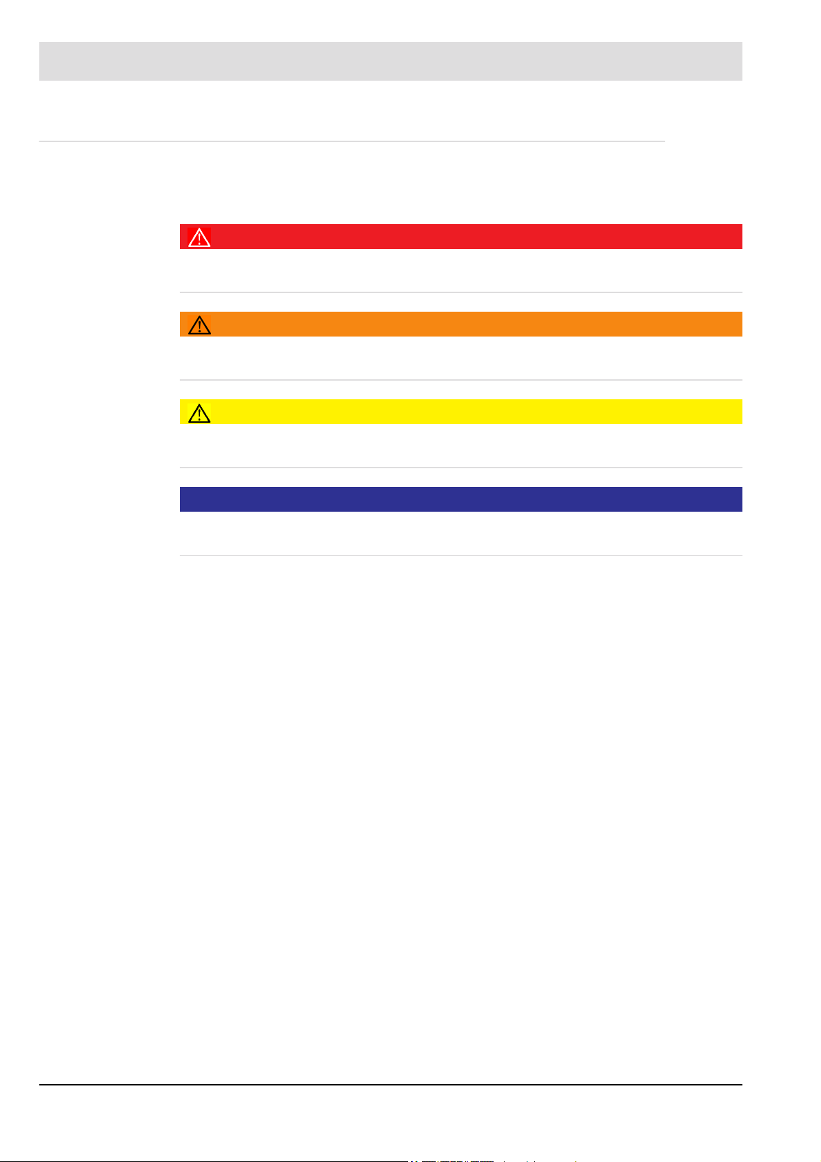
1.3 Classification of the Safety Instructions and Warnings
The following symbols are used in this document to draw the user's attention to important safety information. They are located at points where the information is required. It is essential that
the safety information is observed and followed, and that applies particularly to the warnings.
DANGER!
This draws the user's attention to imminent danger. If it is not avoided, it will result in death or
very serious injury. The plant including its surroundings could be damaged.
WARNING!
This draws the user's attention to the possibility of imminent danger. If it is not avoided, it may
result in death or very serious injury. The plant including its surroundings could be damaged.
CAUTION!
This draws the user's attention to the possibility of imminent danger. If it is not avoided, it may
result in minor injuries. The plant including its surroundings could be damaged.
NOTICE
This draws the user's attention to important additional information about the system or system
components and offers further tips.
The safety information described above is incorporated into the instructions.
Thus, the operator is requested to:
1 Comply with the accident prevention regulations whenever work is being carried out.
2 Do everything possible within his control to prevent personal injury and damage to
property.
5
Page 7

1 General Information
1.4 Terms and Definitions
For further explanations of terms and definitions see IEC 61508-4 (or DIN EN 61508-4).
DC Diagnostic coverage
DC
AVG
E/E/PE-System Electrical/electronic/programmable electronic system
EUC Equipment under control
FIT Failure In Time in 10-9 1/h
FMEDA Failure Mode, Effects, and Diagnostics Analysis
λ
s
λ
d
λ
dd
λ
du
λ
no effect, λdon’t care
HFT Hardware fault tolerance
MooN M out of N channel architecture
MTBF Mean time between failures
MTTR Mean time to repair
MTTF Mean time to failure
PFD Probability of dangerous failure on demand (Low Demand mode)
PFD
AVG
PFH Average frequency of a dangerous failure per hour (Continuous mode)
PTC Proof Test Coverage, proportion of detectable unsafe failures
SFF Safe failure fraction
SIF Safety instrumented function
SIS Safety instrumented system
SIL Safety integrity level
SIL AC Safety integrity level architectural constraint
SC Systematic Capability
T
1
T
2
T
Interval between demands of the safety function
2 IBD
Average diagnostic coverage
Probability of safe failure (detected and undetected)
Probability of dangerous failure
Probability of dangerous detected failure
Probability of dangerous undetected failure
Probability of failures with no effect (not used in SFF calculation)
Average probability of dangerous failure on demand
Proof test interval
Diagnostic test interval
6
Page 8
2 General Safety Instructions
2 General Safety Instructions
2.1 Intended Use
The device is developed and approved for appropriate and intended use. If the device is used
improperly, the protection of personnel and plant is not ensured.
The corresponding manuals or chapters for each particular stage of the product life cycle must
be regarded in addition to this Safety Manual see chapter 1.1 Purpose. Ignoring these instructions will void any warranty and absolve the manufacturer from any liability.
2.2 Safety Functions
The independent compact flame scanner F200K is suitable for flame detection of burners and
combustion systems for gaseous, liquid or solid fuels with permanent operation.
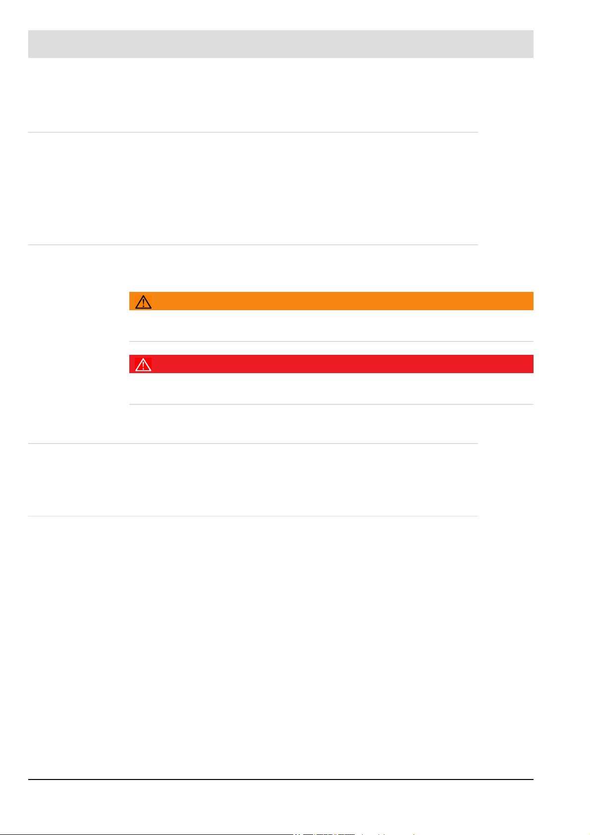
WARNING!
The type approval lapses in the event of modifications to the unit. The unit's inputs and outputs
must be wired according to the specifications in the instruction manual only.
DANGER!
The appendix Hints and requirements for installation, commissioning, operation and
verification" must be considered properly.
2.3 Safe State
The safe state is achieved when the flame signal contact is opened (Flame OFF) and in a
de-energized condition.
2.4 Scope of Application
The F200K flame scanner fulfil
• technical requirements according to DIN EN 61508:2011, part 2 for SIL 3
• the requirements to be used as single device for SIF according to
DIN EN 61511-1:2005-05 up to SIL 3.
• the requirements to be used as single device for safety related control functions (SRCF)
according to EN ISO 13849-1:2006 up to performance level PL e (CAT. 3)
and
• the applicable requirements according to DIN EN 746-2:2011-02 for flame detection in
industrial thermo processing equipment.
7
Page 9

2 General Safety Instructions
2.5 Additional Components
The safety parameters do not include external components such as burner controls or any other sensors and actors.
2.6 Safety Values
The safety values have been determined by the use of a FMEDA with the following basic conditions:
• Component failure rates based on Siemens standard SN 29500, DIN EN 13611: 2011-12
and B10d values of manufactures where no other values are available.
• Specific load parameters, quality factors and an ambient temperature of 60 °C have been
used for the calculation.
• Failure models from DIN EN 13611 and additionally failure model drift have been used.
Under special circumstances short circuits have not to be assumed.
• Estimation of common cause factors β = 2% βD = 1%.
• The "Proof test interval" T1 is equivalent to the product mission or life time.
• The calculation of the safety probability values has been done with a lifetime of 10 years1.
• For redundant structures a diagnostic test interval of T2 = 120s has been defined.
• For redundant subsystems (HFT>=1) the SFF is > 90%, for subsystems without
redundancy (HFT=0) the SFF is > 99%
• The F200K is designed as one safety unit (PES). There is no separation within the
F200K electronic between safety and non safety related components by architectural
design.
• There is no difference between λs detected and undetected. All safe failures can be
assumed as safe undetected (λsu).
1
See chapter 2.7 Life timefor more information.
8
Page 10

2 General Safety Instructions
Device type Type B (complex component)
Mode of operation High demand or continuous mode5
Safety function De-energized flame contact (safety valves)
2
HFT
SIL (SC) 3
λs (λsu) 1,31E+03 FIT
λ
dd
λ
du
λ
no effect
SFF
DC
PFH 1,8E-09 1/h
PFD
T1 10 years
T2 120 seconds
MTTF 28 years
MTTR
MTBF 28 years
3
AVG
AVG
, λ
4
don‘t care
0
6,32E+02 FIT
6,43E+01 FIT
2,04E+03 FIT
96,4%
90,7%
7,2E-05
8 hours
2
According to DIN EN 61508:2011 HFT > 0 requires complete redundancy, including sensors, actors and power sup-
plies. Nevertheless, a HFT=0 device may reach the safety integrity for the usage in SIL3 safety functions according
to DIN EN 61508 or DIN EN 61511 (see 2.4 Scope of Application).
3
SFF is relevant for elements, subsystems or systems in a complete safety loop. This device is always part of a com-
plete safety loop. A SIL calculation of a safety loop must be evaluated finally with the safe failure fraction of elements,
subsystems and the complete system. Nevertheless, the SFF of the device is given in this document for reference.
4
The MTTR is assumed with 8h for the calculation of PFD/PFH (exchange of the device). In practise, the devices will
be locked in the safe state until it is replaced.
5
An electronic safety device without wear which is certified for the usage in safety functions in high demand mode
can be used in low demand functions as well. Therefore the diagnostic test intervall must be sufficient. For F200K
this is given and the PDF
can be used for further calculations.
AVG
9
Page 11

2 General Safety Instructions
2.7 Life time
The mission time or life time of the device is 10 years.
In accordance with the DIN EN 61508 the life time is 8 to 12 years under normal operating
conditions, because electronic components are assumed to have a constant failure rate
λ through this period. After that period the failure rates of the components will increase
significantly with time (see "bathtub curve" for electronic components).
The life time of 10 years does not mean, that the device will become unsafe after this time
immediately. The extensive diagnosis of safety related components remains still active. DIN
EN 61508-2:2011 Note N3 gives the hint, that appropriate measures taken by the
manufacturer and plant operator can extend the useful lifetime.
The burner control is designed for 250.000 switching cycles with nominal switch loads. For
normal operation this is equal to 10 years of operation5. For industrial use with reduced loads
and a lower ambient temperature more switching cycles are possible.
Nevertheless, when the device stays in operation after the end of the life time, LAMTEC does
not guarantees the proper function and all calculated safety values become invalid.
5
Base on the switching cycles and the corresponding lifetime are EN 13611, DIN EN 298 and an overview from the
European Control Manufacturers Association (Afecor, www.afecor.org)
10
Page 12

3 Installation and Commissioning
3 Installation and Commissioning
For installing the device, check the instruction and installation manuals as well as valid norms,
standards and directives for the application (see also chapter 1.2 Standards and Directives).
WARNING!
Connect the device only to other components or devices which are suitable for this safety application.
WARNING!
The Appendix see chapter 7.2 Hints and requirements for installation, commissioning, operation and verification shall be considered properly. Check the installation requirements of IP40
or IP54 in the open air (EN 60529).
WARNING!
For the power supply of the flame detector and for potential separation of the flame detector
contact use the FN20 power supply. Instead of FN20 a safety power supply must be used to
generate the power supply of the flame detector (e.g. According to EN 61558-2-6 or
EN 60950-1).
WARNING!
Use a floating contact which is feeded by the flame detector's 24 V supply for the remote
switching of the F200K2's range. Or use a SELV or PELV power supply according to EN
60730-1 or EN 60950-1 (i.e. a safety power supply).
WARNING!
The current loop for remote indication of the flame intensity must be connected to devices
which have a safe isolation of the measuring circuit to dangerous active parts in accordance
with EN 61140 ( e.g. by double or reinforced isolation in accordance with EN 61010-1). This
can be, for example, passive instruments or isolating transformers with galvanic 3-way isolation.
WARNING!
Models F200K…IR… without line frequency rejection shall be mounted such that they can
only be removed from the mounting fixture by use of a special tool.
NOTICE
The cables are designed for a special temperature range. Do not open the devices in temperatures below -20 °C.
For the commissioning of the F200K please refer to the manual (Chapter 7).
11
Page 13

3 Installation and Commissioning
3.1 Verification
Check the safety functions to ensure the expected operation of the device before using it in a
safety related environment.
DANGER!
Appendix "7.2 B: Conditions" shall be taken into account in an appropriate way.
NOTICE
Checking the Flame Shut-down on Fault:
Simulate a flame rupture or flame extinction by shunting off the fuel supply to the burner to be
monitored by the flame detector. Check that the signal for shutting-off the safety valve is triggered off within the period of TS< 1 s (on safety period 'Operation' at tVOff = 1 s) after extinction of the flame.
'Red' LED lights
'Green' LED dark
For the IR compact flame detectors of the F200K1(2) IR-1 and/or F200K1(2) IR-2 types, take
into account the radiation effects characteristic of the combustion chamber. Consequently,
switch-off tests should be carried out when the boiler has reached operating temperature. In
particular, make sure that the sensitivity of the compact flame detector is increased only to
such a value required to safely and reliably monitor the flame throughout the operating range
of the burner.
12
Page 14

4 Operation
4 Operation
During operation the device must not be deactivated or bypassed. The operator must be familiar with the displayed information of the device and the measures to be executed in the
moment of any signalized disturbance. The information in the instruction manual must be
regarded.
Only suitable elements and devices must be connected, also for the commission of the device
(see chapter 2.5 Additional Components).
Failures must be reported to LAMTEC as soon as possible.
Danger to life and material: Do not put the safety loop out of service
4.1 Proof Test
WARNING!
DANGER!
The "Proof Test Interval" T1 is equivalent to the product`s mission or life time. There are no
components or elements used that can be set into an "as new condition" by a proof test of
the device.
Nevertheless, a proof test can ensure proper operation and decrease the average probability
of dangerous failure on demand (PFD
According to DIN EN 61508:2011-6, the PFD
coverage (PTC, proportion of detectable unsafe failures through a proof test), a proof test
interval (T1) and a request interval of the safety function (T
4.2 Proof Test Calculation and PTC
The PFD
Exemplarily the calculation is done with a request interval (T
and a proof test interval (T1) of 1 year.
The F200K the following PTCs are calculated:
– PTC = 70% for a basic proof test (see chapter 4.3) of the device
– PTC = 98% for a advanced proof test of the device by LAMTEC
– PTC = 100% exchange with a new device
T1= 1 year
T2 IBD [a]
1 6,4E-06 6,4E-06 6,4E-06
2 8,7E-06 7,1E-06 6,4E-06
3 1,1E-05 7,7E-06 6,4E-06
4 1,3E-05 8,3E-06 6,4E-06
5 1,6E-05 9,0E-06 6,4E-06
10 2,8E-05 1,2E-05 6,4E-06
can be calculated with the formulas of the DIN EN 61508-6:2011, B.3.2.5.
AVG
PTC 70%
PFD
AVG
) during the defined mission time.
AVG
can be calculated by the use of a proof test
AVG
).
2 IBD
) of 1,2,3,4,5 and 10 years
2 IBD
PTC 98%
PFD
AVG
PTC 100%
PFD
AVG
13
Page 15

4 Operation
4.3 Proof Test Execution
To execute a proof test, the following test equipment is needed:
– Continuity tester with test current <= 50mA
– LAMTEC proof spotlight FFP30 (659M5000) or any suitable flame simulation
– LAMTEC operation manual F200K DLT7620
For the proof test of the F200K, the flame states ON and OFF must be stimulated. During the
test, the F200K is connected to the operating voltage.
WARNING!
The proof test is done with a continuity tester at the connecting cables oft the flame relay. To
protect the environment and to guarantee the correctness oft the test, the cables of the flame
relay (BN, GN, WH) must be disconnected before starting the test sequence.
DANGER!
If the cables of the flame relay (BN, GN, WH) are not disconnected completely, dangerous
voltages can be applied at the cable contacts.
To execute a basic proof test with a PTC of 70% for the F200K series, the following test steps
must be executed and approved.
– Disconnect cables BN, GN, WH (see operation manual DLT7620 chapter Circuit
Diagrams).
– Simulate state flame OFF.
– LED OFF (red) lights up (see operation manual DLT7620 chapter Appendix ‘Layout of the
Operational Controls‘).
– The flame relay opening contacts must be closed (cables BN and WH connected).
– The flame relay closing contacts must be open (cables BN and GN disconnected).
– Simulate state flame ON.
– LED ON (green) lights up and pulses (see operation manual DLT7620 chapter Appendix
Layout of the Operational Controls).
– The flame relay opening contacts must be opened (cables BN and WH disconnected).
– The flame relay closing contacts must be closed (cables BN and GN connected).
– Connect cables BN, GN, WH and check the proper operation of the device in the applica-
tion.
14
Page 16

5 Repair and Maintenance
5 Repair and Maintenance
WARNING!
The device must not be repaired, modified or manipulated. Otherwise the safety integrity can
be lost and LAMTEC will not guarantee for the proper operation any more.
NOTICE
Defects and failures must be reported to LAMTEC as soon as possible, including type, version
and serial number of the device.
In case of a repair or maintenance, comply with instructions from the installation manual.
Defective devices must be sent to LAMTEC for a repair. The safe operation of the application
must be ensured while the device is being repaired or a maintenance is ongoing. After a repair
or a maintenance, follow chapter 3 Installation and Commissioning again.
WARNING!
Replace the device only by one of the same type and version and check the corresponding
data and parameter set.
DANGER!
The flame detector is a safety device. Any repair work or other changes to the device shall
only be carried out by the manufacturer's specialist staff or by some other persons appointed
by the manufacturer. Any other persons are not allowed to operate on parts inside the device.
In particular, this concerns the unauthorized exchange of the flame contact fuse. Any unauthorized replacement, repair or modification of the device can lead to a loss of the safety
integrity.
15
Page 17

6 Decommission and Dismount
6 Decommission and Dismount
To put the device out of service, comply with instructions from the installation manual and
ensure the safe operation of the application after that. The device should be replaced after the
product`s mission or life time (see chapter 2.7 Life time).
The device must be disposed properly. This device is designed for industrial usage and must
be disposed accordingly.
16
Page 18

7 Appendix
7 Appendix
7.1 TÜV Confirmation
17
Page 19

7 Appendix
18
Page 20

7 Appendix
7.2 Hints and requirements for installation, commissioning, operation and verification
19
Page 21

8 EU Declaration of Conformity
8 EU Declaration of Conformity
20
Page 22

8 EU Declaration of Conformity
21
Page 23

8 EU Declaration of Conformity
22
Page 24

The information in this publication is subject to technical changes.
LAMTEC Meß- und Regeltechnik
für Feuerungen GmbH & Co. KG
Wiesenstraße 6
D-69190 Walldorf
Telefon: +49 (0) 6227 6052-0
Telefax: +49 (0) 6227 6052-57
info@lamtec.de
www.lamtec.de
Printed in Germany | Copyright 2019
Publication no. DLT7604-19-aEN-006
 Loading...