

Page 1

Manual
F200K Compact Flame Scanner
Sensors and Systems for Combustion Engineering
www.lamtec.de
Page 2

Page 3

Table of Contents
Table of Contents
1 General Information. . . . . . . . . . . . . . . . . . . . . . . . . . . . . . . . . . . . . . . . . . . . . . . . . . . . . . . . . 5
1.1 Validity of these Instructions. . . . . . . . . . . . . . . . . . . . . . . . . . . . . . . . . . . . . . . . . . . . . . . 5
1.2 Purpose . . . . . . . . . . . . . . . . . . . . . . . . . . . . . . . . . . . . . . . . . . . . . . . . . . . . . . . . . . . . . . 5
1.3 Target Group . . . . . . . . . . . . . . . . . . . . . . . . . . . . . . . . . . . . . . . . . . . . . . . . . . . . . . . . . . 6
1.4 Safekeeping of the Manual . . . . . . . . . . . . . . . . . . . . . . . . . . . . . . . . . . . . . . . . . . . . . . . 6
2 Safety . . . . . . . . . . . . . . . . . . . . . . . . . . . . . . . . . . . . . . . . . . . . . . . . . . . . . . . . . . . . . . . . . . . . 7
2.1 For Your Safety . . . . . . . . . . . . . . . . . . . . . . . . . . . . . . . . . . . . . . . . . . . . . . . . . . . . . . . . 7
2.2 How to Use the Information . . . . . . . . . . . . . . . . . . . . . . . . . . . . . . . . . . . . . . . . . . . . . . . 7
2.3 Product Safety . . . . . . . . . . . . . . . . . . . . . . . . . . . . . . . . . . . . . . . . . . . . . . . . . . . . . . . . . 7
2.4 Product-specific Dangers. . . . . . . . . . . . . . . . . . . . . . . . . . . . . . . . . . . . . . . . . . . . . . . . . 8
3 Functional Description . . . . . . . . . . . . . . . . . . . . . . . . . . . . . . . . . . . . . . . . . . . . . . . . . . . . . . 9
3.1 Design . . . . . . . . . . . . . . . . . . . . . . . . . . . . . . . . . . . . . . . . . . . . . . . . . . . . . . . . . . . . . . . 9
3.2 Rating Plate . . . . . . . . . . . . . . . . . . . . . . . . . . . . . . . . . . . . . . . . . . . . . . . . . . . . . . . . . . . 9
3.3 Mode of operation . . . . . . . . . . . . . . . . . . . . . . . . . . . . . . . . . . . . . . . . . . . . . . . . . . . . . 10
3.4 Basic circuit diagram . . . . . . . . . . . . . . . . . . . . . . . . . . . . . . . . . . . . . . . . . . . . . . . . . . . 11
4 Technical Data . . . . . . . . . . . . . . . . . . . . . . . . . . . . . . . . . . . . . . . . . . . . . . . . . . . . . . . . . . . . 12
4.1 Characteristics. . . . . . . . . . . . . . . . . . . . . . . . . . . . . . . . . . . . . . . . . . . . . . . . . . . . . . . . 12
4.2 Operating conditions . . . . . . . . . . . . . . . . . . . . . . . . . . . . . . . . . . . . . . . . . . . . . . . . . . . 12
4.3 Life Cycle. . . . . . . . . . . . . . . . . . . . . . . . . . . . . . . . . . . . . . . . . . . . . . . . . . . . . . . . . . . . 16
5 Selection Criteria . . . . . . . . . . . . . . . . . . . . . . . . . . . . . . . . . . . . . . . . . . . . . . . . . . . . . . . . . . 17
6 Information for Mounting and Installation. . . . . . . . . . . . . . . . . . . . . . . . . . . . . . . . . . . . . . 18
6.1 Mounting - Basic Instructions. . . . . . . . . . . . . . . . . . . . . . . . . . . . . . . . . . . . . . . . . . . . . 18
6.1.1 Safety. . . . . . . . . . . . . . . . . . . . . . . . . . . . . . . . . . . . . . . . . . . . . . . . . . . . . . . . . 18
6.1.2 UL Listed . . . . . . . . . . . . . . . . . . . . . . . . . . . . . . . . . . . . . . . . . . . . . . . . . . . . . . 18
6.1.3 Basic mounting instructions. . . . . . . . . . . . . . . . . . . . . . . . . . . . . . . . . . . . . . . . 19
6.2 Installation . . . . . . . . . . . . . . . . . . . . . . . . . . . . . . . . . . . . . . . . . . . . . . . . . . . . . . . . . . . 20
6.2.1 External Installation . . . . . . . . . . . . . . . . . . . . . . . . . . . . . . . . . . . . . . . . . . . . . . 20
6.2.2 Device Connection. . . . . . . . . . . . . . . . . . . . . . . . . . . . . . . . . . . . . . . . . . . . . . . 21
7 Instructions on Commissioning and Maintenance. . . . . . . . . . . . . . . . . . . . . . . . . . . . . . . 22
7.1 Display and Operational Controls . . . . . . . . . . . . . . . . . . . . . . . . . . . . . . . . . . . . . . . . . 22
7.1.1 Intensity Indicator Including the 'Adjust' Function . . . . . . . . . . . . . . . . . . . . . . . 22
7.1.2 Operating State - Indication. . . . . . . . . . . . . . . . . . . . . . . . . . . . . . . . . . . . . . . . 22
7.1.3 Operating Mode - Display . . . . . . . . . . . . . . . . . . . . . . . . . . . . . . . . . . . . . . . . . 22
7.1.4 Sensitivity - Switch. . . . . . . . . . . . . . . . . . . . . . . . . . . . . . . . . . . . . . . . . . . . . . . 23
7.1.5 Frequency - Switch . . . . . . . . . . . . . . . . . . . . . . . . . . . . . . . . . . . . . . . . . . . . . . 23
7.1.6 Service - Switch Serv. . . . . . . . . . . . . . . . . . . . . . . . . . . . . . . . . . . . . . . . . . . . . 23
7.1.7 Adjust - Switch. . . . . . . . . . . . . . . . . . . . . . . . . . . . . . . . . . . . . . . . . . . . . . . . . . 23
7.1.8 Start-up Suppression - Potentiometer . . . . . . . . . . . . . . . . . . . . . . . . . . . . . . . . 23
7.1.9 Measuring Points. . . . . . . . . . . . . . . . . . . . . . . . . . . . . . . . . . . . . . . . . . . . . . . . 24
7.2 Commissioning . . . . . . . . . . . . . . . . . . . . . . . . . . . . . . . . . . . . . . . . . . . . . . . . . . . . . . . 25
7.2.1 General Information. . . . . . . . . . . . . . . . . . . . . . . . . . . . . . . . . . . . . . . . . . . . . . 25
7.2.1.1 'Flame Out' State . . . . . . . . . . . . . . . . . . . . . . . . . . . . . . . . . . . . . . . . . . . . . . . . 25
7.2.1.2 'Flame In' State . . . . . . . . . . . . . . . . . . . . . . . . . . . . . . . . . . . . . . . . . . . . . . . . . 25
7.2.1.3 Operating mode switchover. . . . . . . . . . . . . . . . . . . . . . . . . . . . . . . . . . . . . . . . 25
2
Page 4

Table of Contents
7.2.2 Special Points to Note When Using the Device in Explosion-proof Areas. . . . . 25
7.2.3 Preparations . . . . . . . . . . . . . . . . . . . . . . . . . . . . . . . . . . . . . . . . . . . . . . . . . . . 27
7.2.3.1 Checking the Compact Flame Scanner. . . . . . . . . . . . . . . . . . . . . . . . . . . . . . . 27
7.2.3.2 Alignment. . . . . . . . . . . . . . . . . . . . . . . . . . . . . . . . . . . . . . . . . . . . . . . . . . . . . . 28
7.2.3.3 Optics. . . . . . . . . . . . . . . . . . . . . . . . . . . . . . . . . . . . . . . . . . . . . . . . . . . . . . . . . 28
7.2.4 Settings . . . . . . . . . . . . . . . . . . . . . . . . . . . . . . . . . . . . . . . . . . . . . . . . . . . . . . . 29
7.2.4.1 Sensitivity. . . . . . . . . . . . . . . . . . . . . . . . . . . . . . . . . . . . . . . . . . . . . . . . . . . . . . 29
7.2.4.2 Alignment with Adjustment Function . . . . . . . . . . . . . . . . . . . . . . . . . . . . . . . . . 29
7.2.4.3 Measuring Points. . . . . . . . . . . . . . . . . . . . . . . . . . . . . . . . . . . . . . . . . . . . . . . . 29
7.2.4.4 Frequency Settings . . . . . . . . . . . . . . . . . . . . . . . . . . . . . . . . . . . . . . . . . . . . . . 30
7.2.4.5 Start-up Suppression. . . . . . . . . . . . . . . . . . . . . . . . . . . . . . . . . . . . . . . . . . . . . 30
7.2.5 Switch-off test - check the correct setting . . . . . . . . . . . . . . . . . . . . . . . . . . . . . 31
7.2.6 Fault on Flame Detection. . . . . . . . . . . . . . . . . . . . . . . . . . . . . . . . . . . . . . . . . . 31
7.2.6.1 1. Interference . . . . . . . . . . . . . . . . . . . . . . . . . . . . . . . . . . . . . . . . . . . . . . . . . . 31
7.2.6.2 2. Exceeding the permissible ambient temperature. . . . . . . . . . . . . . . . . . . . . . 31
7.2.7 Faults During Ignition. . . . . . . . . . . . . . . . . . . . . . . . . . . . . . . . . . . . . . . . . . . . . 32
7.2.8 Faults During Operation. . . . . . . . . . . . . . . . . . . . . . . . . . . . . . . . . . . . . . . . . . . 32
7.3 Troubleshooting. . . . . . . . . . . . . . . . . . . . . . . . . . . . . . . . . . . . . . . . . . . . . . . . . . . . . . . 33
7.4 Commissioning Flow Chart . . . . . . . . . . . . . . . . . . . . . . . . . . . . . . . . . . . . . . . . . . . . . . 33
7.5 Maintenance . . . . . . . . . . . . . . . . . . . . . . . . . . . . . . . . . . . . . . . . . . . . . . . . . . . . . . . . . 36
7.5.1 General Information. . . . . . . . . . . . . . . . . . . . . . . . . . . . . . . . . . . . . . . . . . . . . . 36
7.5.2 Instructions on Troubleshooting. . . . . . . . . . . . . . . . . . . . . . . . . . . . . . . . . . . . . 36
7.5.3 Flame Scanner Testing Device replace Battery. . . . . . . . . . . . . . . . . . . . . . . . . 36
8 Warranty and Delivery Terms . . . . . . . . . . . . . . . . . . . . . . . . . . . . . . . . . . . . . . . . . . . . . . . . 38
9 Appendix. . . . . . . . . . . . . . . . . . . . . . . . . . . . . . . . . . . . . . . . . . . . . . . . . . . . . . . . . . . . . . . . . 39
9.1 Layout of the Operational Controls . . . . . . . . . . . . . . . . . . . . . . . . . . . . . . . . . . . . . . . . 39
9.1.1 F200K1 ... in the State as Delivered . . . . . . . . . . . . . . . . . . . . . . . . . . . . . . . . . 39
9.1.2 F200K2... (Ex-proof), in the State as Delivered. . . . . . . . . . . . . . . . . . . . . . . . . 40
9.2 Dimensions . . . . . . . . . . . . . . . . . . . . . . . . . . . . . . . . . . . . . . . . . . . . . . . . . . . . . . . . . . 41
9.2.1 F200K and F200K Ex-II (Hazardous Area 2.22) Compact Flame Scanner. . . . 41
9.2.2 F200K2 ... Ex Compact Flame Detector (Hazardous Area 1, 21) . . . . . . . . . . . 42
9.2.3 Connection Housing FG 24 Ex . . . . . . . . . . . . . . . . . . . . . . . . . . . . . . . . . . . . . 43
9.3 Circuit Diagrams . . . . . . . . . . . . . . . . . . . . . . . . . . . . . . . . . . . . . . . . . . . . . . . . . . . . . . 44
9.3.1 Circuit Diagram F200K1 ... . . . . . . . . . . . . . . . . . . . . . . . . . . . . . . . . . . . . . . . . 44
9.3.2 Circuit Diagram F200K2 ... EX. . . . . . . . . . . . . . . . . . . . . . . . . . . . . . . . . . . . . . 45
9.4 Examples of Application. . . . . . . . . . . . . . . . . . . . . . . . . . . . . . . . . . . . . . . . . . . . . . . . . 46
9.4.1 Interfacing with ETAMATIC . . . . . . . . . . . . . . . . . . . . . . . . . . . . . . . . . . . . . . . . 46
9.4.2 Interfacing with FMS . . . . . . . . . . . . . . . . . . . . . . . . . . . . . . . . . . . . . . . . . . . . . 47
10 Accessories . . . . . . . . . . . . . . . . . . . . . . . . . . . . . . . . . . . . . . . . . . . . . . . . . . . . . . . . . . . . . . 48
10.1 FN20, FN30-20 Power Supply. . . . . . . . . . . . . . . . . . . . . . . . . . . . . . . . . . . . . . . . . . . . 48
10.1.1 Purpose . . . . . . . . . . . . . . . . . . . . . . . . . . . . . . . . . . . . . . . . . . . . . . . . . . . . . . . 48
10.1.2 Technical Data. . . . . . . . . . . . . . . . . . . . . . . . . . . . . . . . . . . . . . . . . . . . . . . . . . 48
10.1.3 Pin Assignment . . . . . . . . . . . . . . . . . . . . . . . . . . . . . . . . . . . . . . . . . . . . . . . . . 50
10.2 Weather Shield. . . . . . . . . . . . . . . . . . . . . . . . . . . . . . . . . . . . . . . . . . . . . . . . . . . . . . . . 53
10.3 Adjustable Holding Devices. . . . . . . . . . . . . . . . . . . . . . . . . . . . . . . . . . . . . . . . . . . . . . 54
10.3.1 FH30-10 (for IR and UV, without Ball-and-socket-joint with Purge Air Connec-
tion) . . . . . . . . . . . . . . . . . . . . . . . . . . . . . . . . . . . . . . . . . . . . . . . . . . . . . . . . . . 54
10.3.2 FH40-10 (for IR and UV, with Ball-and-socket-joint and Purge Air Connection) . 55
3
Page 5

Table of Contents
10.3.3 FV30-10 (for IR and UV, without Ball-and-socket-joint with Purge Air Connec-
tion) . . . . . . . . . . . . . . . . . . . . . . . . . . . . . . . . . . . . . . . . . . . . . . . . . . . . . . . . . . 56
10.3.4 FV40-10 (for IR and UV, with Ball-and-socket-joint and Purge Air Connection) . 56
10.3.5 Cooling Air Housing FS50 . . . . . . . . . . . . . . . . . . . . . . . . . . . . . . . . . . . . . . . . . 58
10.3.6 Cooling Air Housing with Ball-and-Socket Joint FS51. . . . . . . . . . . . . . . . . . . . 59
10.3.7 FS56 (Adjustable, Demountable, with Cooling Air Housing) . . . . . . . . . . . . . . . 60
10.4 Installation in the Cooling Air Housing. . . . . . . . . . . . . . . . . . . . . . . . . . . . . . . . . . . . . . 60
10.5 Flame Scanner Testing Device . . . . . . . . . . . . . . . . . . . . . . . . . . . . . . . . . . . . . . . . . . . 62
10.6 Connection Cable AK01. . . . . . . . . . . . . . . . . . . . . . . . . . . . . . . . . . . . . . . . . . . . . . . . . 63
10.6.1 Purpose . . . . . . . . . . . . . . . . . . . . . . . . . . . . . . . . . . . . . . . . . . . . . . . . . . . . . . . 63
10.6.2 Technical Data. . . . . . . . . . . . . . . . . . . . . . . . . . . . . . . . . . . . . . . . . . . . . . . . . . 64
10.7 Fiber Optic . . . . . . . . . . . . . . . . . . . . . . . . . . . . . . . . . . . . . . . . . . . . . . . . . . . . . . . . . . . 64
11 Commissioning Protocol. . . . . . . . . . . . . . . . . . . . . . . . . . . . . . . . . . . . . . . . . . . . . . . . . . . . 67
12 EU Declaration of Conformity. . . . . . . . . . . . . . . . . . . . . . . . . . . . . . . . . . . . . . . . . . . . . . . . 68
4
Page 6

1 General Information
1 General Information
1.1 Validity of these Instructions
This document is valid for the F200K Compact Flame Scanner with hardware version 2.0 until
2.2
The devices correspond to the following directives and standards:
• DIN EN 298: 2012
• DIN EN 60730-2-5: 2015
• DIN EN 746-2: 2011
• 2014/68/EU Pressure Equipment Directive
• 2009/142/EG Gas Appliance Directive
• EU/2016/426 Gas Appliance Regulation (GAR)
• 2014/30/EU Electromagnetic Compatibility Directive
• 2014/35/EU Low Voltage Directive
• DIN EN 61508: 2011, part 2 (requirements SIL 3)
• DIN EN ISO 9001:2008 Quality Management Systems
• ISO/IEC 80079-34:2011 Potentially explosive areas - Quality Management System
(QAR)
• 2011/65/EU (RoHS2 Directive)
• UL372
1.2 Purpose
Product-Identification-Number: CE-0085 BO 0005
NOTICE
LAMTEC retains the right to make changes to this document at any time, without notice.
LAMTEC makes no warranty of any kind, expressed or implied, with regard to any
information contained in this document, including, but not limited to, the implied warranties of
merchantability or fitness for any particular purpose.
Further LAMTEC does not warrant the accuracy or completeness of the information, text,
graphics, or other items contained within this document.
In single-burner and multiple-burner furnaces, the flame scanner performs a high-safety monitoring of the burner flame. When the flame goes out, the safe control state’ Flame ’ is reached.
The flame scanner is mainly used in large-scale power plants, thermal power stations and
chemical plants as well as for monitoring furnaces which are operated from.
– oil
– gas
– bio-mass
– dust coal
– chemicals and other waste products
5
Page 7

1 General Information
1.3 Target Group
These instructions must have been read carefully and completely before commencing with
any work. The basic prerequisite for working safely is compliance with all the specified safety
instructions.
NOTICE
All assembly , commissioning, troubleshooting and maintenance work may only be carried
out by authorised and trained personnel.
The device may be operated and maintained only by those who are capable of doing so
in terms of their level of knowledge and training.
For F200K, the covers must be removed for commissioning, but then only by authorised
personnel. Any further opening or disassembly is not permitted.
The open flame scanner must be protected from ingress of dust and moisture.
Contact with the electronics is only permitted if ESD measures are observed.
Opening the devices is not permitted under any circumstances except for commissioning
(F200K).
For safety reasons, access to parameterisation must be restricted to authorised
personnel.
1.4 Safekeeping of the Manual
Look after the manual and all the associated documents carefully.
The manual is part of the product and must be kept safe and be accessible to personnel at all
times.
Moreover, it is important that the manual:
• Is available when required.
• Is kept for the entire service life of the device.
• Is available to its next operator.
6
Page 8
2 Safety
2 Safety
2.1 For Your Safety
The following symbols are used in this document to draw the user's attention to important safety information. They are located at points where the information is required. It is essential that
the safety information is observed and followed, and that applies particularly to the warnings.
This draws the user's attention to imminent danger. If it is not avoided, it will result in death or
very serious injury. The plant including its surroundings could be damaged.
This draws the user's attention to the possibility of imminent danger. If it is not avoided, it may
result in death or very serious injury. The plant including its surroundings could be damaged.
This draws the user's attention to the possibility of imminent danger. If it is not avoided, it may
result in minor injuries. The plant including its surroundings could be damaged.
DANGER!
WARNING!
CAUTION!
NOTICE
This draws the user's attention to important additional information about the system or system
components and offers further tips.
The safety information described above is incorporated into the instructions.
Thus, the operator is requested to:
1 Comply with the accident prevention regulations whenever work is being carried out.
2 Do everything possible within his control to prevent personal injury and damage to prop-
erty.
2.2 How to Use the Information
The necessary data for correct mounting, wiring, installation, operation and maintenance of
the device are to be taken from the relevant instructions for the burner or combustion in the
official language of the country.
7
Page 9

2 Safety
2.3 Product Safety
WARNING!
This product is state-of-the-art technology and complies with the generally accepted
safety-related rules and regulations.
Every device is tested before delivery to ensure that it is working properly and safely.
Only use this product when it is perfect condition and in accordance with the manual, the
prevailing regulations and guidelines and the applicable safety and accident prevention
regulations.
WARNING!
The risk of danger in the event of external fire, traffic and wind, flood waves and earthquakes
depend on the installation situation and the installation site to be assessed separately where
appropriate.
2.4 Product-specific Dangers
DANGER!
The F200K is not designed to switch off the fuel valves.
The subsequent signal processing must be carried out in the control system, which is
adapted to suit the combustion plant.
WARNING!
The F200K is a safety device. Only specialist staff of the manufacturer or people approved by
the manufacturer may intervene. No interventions by anyone else are permissible. This applies, in particular, in the event of a defective fuse.
WARNING!
Radio interference suppression of the output contacts
In the interests of safety, ensure when installing the output contacts that:
The user suppresses radio interference in such a way that the contacts of the safety relay
contact output cannot be shorted by defective components of the suppressor circuitry.
WARNING!
The power supply of the flame scanner and the user interface with 24 VDC must be ensured
by an external power supply unit, which supplies SELV or PELV.
8
Page 10

3 Functional Description
3 Functional Description
3.1 Design
The compact-type flame detector is composed of a cylindrical casing comprising an axial light
incidence aperture, a processing status indicator at the rear of the unit and operational controls which can be accessed by removing the cover.
When closed the flame detector complies with the requirements of IP 67 (F200K) or IP66
(F200K..EX) protection degree.
The detector is installed at the burner by optionally using the FH30, FV30, FH40, FV40 adjustable holding devices or with an air-cooled housing of types FS50, FS51 or FS56.
The detector consists of the following functional units:
– sensor unit providing for digitalisation of the flame signal
– digital frequency evaluation
– self-monitoring
– switching amplifier
The device is connected through an integrated standard plug and using the a connection cable
required for this (8 pins, static shielded) with coupler.
The cable provides for the following connections:
– Infeed of power supply
– connection of the operational earthing FPE
– connection of external power circuits to a failsafe change-over contact to control the con-
trol states ’Flame out’ and ’Flame in’
– connection of the intensity measurement output
– connection for an external sensitivity change-over, only for F200K2
– connection of the screen via the connector housing
The layout of the operational controls is represented in chapter 9.1 Layout of the Operational
Controls.
9
Page 11

3 Functional Description
3.2 Rating Plate
Rating plate F200K (Example):
Information on variants:
a Housing type:
Ex= zone1, EXII=zone2,
empty/0 = Standard,
FO= Fiber optic,
V= screwed
b Electronic type
c Electronic type
d FFTD: 1 ... 4
e Mains frequency: 50, 60,--
f Output current min.: 0, 4
g ERP number
h Serial number
i Hardware version
10
Page 12

3 Functional Description
3.3 Mode of operation
The compact flame detector converts the flame radiation pulsing of the burner flame into electrical signals. These signals are routed to an electronic changeover switch, which alternately
applies them to one of the independently working processing channels, where the signals are
digitised. This reduces the initial signal quantity to the information ’pulse period’ (information
carrier: pulse frequency of the flame radiation).
The digitised signals are compared with the related reference signals by means of a digital
frequency evaluation unit. This ensures that only those flame signals that are within the preselected frequency transmission range will be included in a continued processing, irrespective
of their original amplitude. A control switch (for the F200K2 only) located below the removable
cover allows the operator to change the lower frequency limit if required. After evaluation, the
flame signal is routed to the switching amplifier, which also controls the related shut-down
time.
A safe monitoring of the antivalent control states as well as the response and shut-down periods is performed at the output of the signal processing channels, before an activation of the
output relays at the end of each signal processing channel is carried out. Antivalence faults
and deviation in time delays going beyond the admissible limit values result in the control state
’Flame out’.
The control states ’Flame out’ and ’Flame in’ are indicated on the rear side of the device by
means of a red and/or green LED. The change-over between the two signal processing channels is indicated by pulsing of the green LED during the ’Flame in’ control state.
Additionally one or two six-step control switches provide for a sensitivity adjustment to adapt
the system to the flames to be monitored, this being indicated by means of a six-step chain of
green LEDs designed to be the device's flame intensity indicator.
Miscellaneous
Self-monitoring principle
Signal processing is carried out by means of two transmission channels working independently of each other and alternately triggered. The output levels are permanently checked for antivalence within a given time grid.
Parameter adjustment, combustion system type monitoring equipment
Using the control rotary switch on the F200K/F200K2 compact flame detectors enables between 6 and 12 sensitivity levels to be set. The F200K2 version allows an increased sensitivity
in range II to be set. A six-step green LED indicator indicates the evaluated flame intensity on
the rear side of the device. The transmission range of the digital flame frequency evaluation
allows for signal passage between10 ... 190 Hz (F200K1) and/or 10 / 20 / 30 ... 190 Hz
(F200K2).
11
Page 13
3 Functional Description
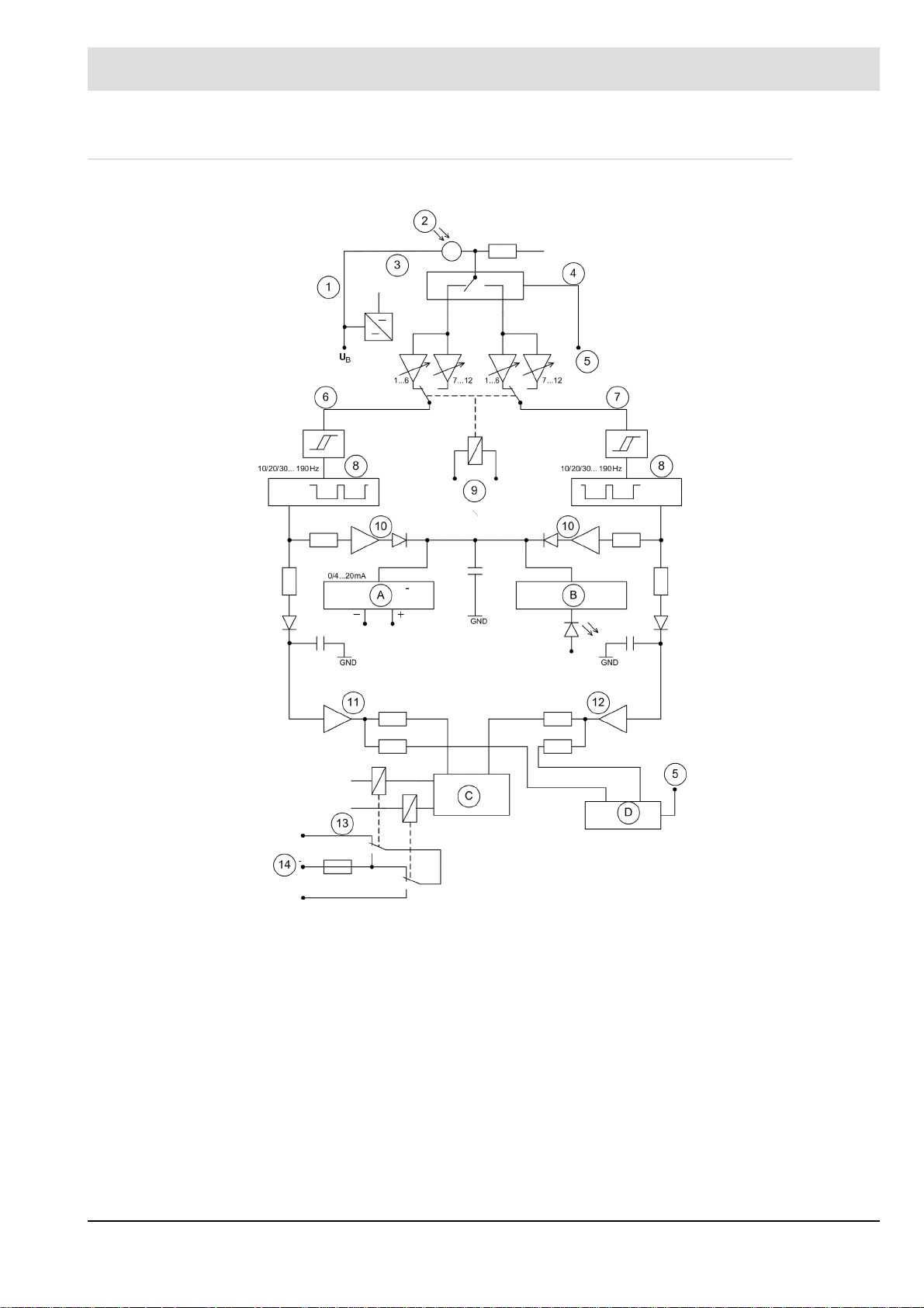
3.4 Basic circuit diagram
Fig. 3-1 Basic circuit diagram
A Intensity remote indicator C Self-monitoring
B Visual intensity indicator D Monitoring cycle
1 Stabilisation 8 Digital band pass
2 Flame sensor 9 Sensitivity selector switch
3 Detector 10 Safe de-coupling
4 Switch-over contact 11 Switching amplifier channel A
5 Cycle 12 Switching amplifier channel B
6 Channel A 13 Output relay
7 Channel B 14 Output contacts
12
Page 14

4 Technical Data
4 Technical Data
4.1 Characteristics
The compact flame scanner is available in 2 basic versions, as well as an ex-proof enclosure
type with several spectral varieties (IR / UV).
Design type F200K1 F200K2
Sensitivity range 1 sensitivity range
6 levels
Frequency range 10 ...190 Hz* *10/20/30 ... 190 Hz
* Special versions with regard to the lower limit frequencies are available on request
NOTICE
Signals lying in the mains frequency range or its multiples are suppressed for 50 Hz mains
generally. For 60 Hz application, please indicate separately in your order form. The related
stop ranges are changed in factory.
LAMTEC offers a version without mains frequency suppression for special applications.
This design requires additional measures during installation.
Please contact LAMTEC Support for further information
The compact flame scanner is accordingly marked by a rating plate.
2 sensitivity range
increased sensitivity in
range II, can externally be
switched over, 6 levels
each
can be adjusted on the
device
13
Page 15

4 Technical Data
4.2 Operating conditions
Input parameters
Auxiliary energy, input
- Supply voltage 24 VDC ± 20 %, protection class III
- Power consumption 4 W, 380 mA (100 ms peak)
- Switch ON current 28.8 V 750 mA (100 ms peak)
spectral radiation range and sight angle
- F200K1 UV-2 and F200K2 UV-2(Ex) 210 ... 380 nm about 8°
- F200K1 UV-3 and F200K2 UV-3(Ex) 210 ... 380 nm about 8°
- F200K2 UV-6(Ex) 215 ... 360 nm about 10°
- F200K1 IR-2 and F200K2 IR-2(Ex) 850 … 1200 nm about 50°
- F200K1 IR-1 and F200K2 IR-1(Ex) 1200 ... 2800 nm about 60°
Response sensitivity 25 mV AC
Range remote switch-over (F200K2 only) floating-contact, can be controlled by means of
the supply voltage (refer to chapter 9.3 Circuit Diagrams and 9.4.2 Interfacing with FMS).
- Input control current ca. 10 mA
Output parameters
Output contact Change-over contact (floating)
- Permissible switching voltage max. 50 VDC, protection class II
(250 VAC by main supply
FN 20)
min. 6 VAC/DC
- Permissible switching current max. 0,5 A at < 60°C/+140 °F
0,4 A at < 75 °C/+167 °F
min. 1 mA, at a limit load of 50 mA
- Switching capacity min. 0,1 W
max. 30 W
- Internal fuses 2,5 A slow IEC or
3,5 A slow UL
- Safety time ’FFDT’ t
- Start-up delay t
1 s or 2 ... 4 s, factory set
VAus
FFDT
VEin
NOTICE
The output contacts of the flame detector have no radio interference suppression. The user is
required to take the appropriate radio interference suppression measures on the basis of the
overall installation design.
In order to ensure the required safety, carry out the installation circuitry in such a way as to
avoid shorting-out of the contacts by defective components of the interference suppression
unit.
14
Page 16

4 Technical Data
Measuring output for intensity
- Output continuous current 0/4 ... 20 mA, there is no insulation of
- Maximum working resistance 200
- Floating DC voltage 6,6 V
- Basic error 2 %
Dynamic characteristics
Self-monitoring cycle t
Cable length
Maximum extension via the connection cable
3 m/9,84 ft addition, at a supply voltage 20,5 V
Deviating cable lengths p. ex.
(main criteria is the compliance to limitations of the
supply voltage the compact flame scanner and thus
the loss of voltage on the supply line)
potential towards the supply voltage
ca. 3,0 s for safety time
TAKT
t
1 s
VAus
t
ca. 7,0 s for safety time
TAKT
t
3 s
VAus
2
Wire 0.5 mm
/20 AWG length: 50
m/164 ft
Wire 1.0 mm2/18 AWG length:
100 m/328 ft
Wire 2.5 mm
2
/14 AWG length:
250 m/820 ft
length: 150 m/492 ft
Wire: 0.5 mm² / 20 AWG
150 : 0.5 x 0.0131 +19.2 = 23.13 V
The supply voltage must be
> 23.13 V
NOTICE
Only a cross-section of 0.5 mm²/20 AWG is possible for the F200K Ex.
Technical conditions
Operating mode DB – continuous operation
Intermittent operation
72h Operation according to TRD604
Creepage distances and clearances IEC 60730-1:2010, ÜK III, VG 2
Interference susceptibility IEC 60730-1:2010, EN 61000-4
Emitted interference DIN EN 55011/A1, class B
15
Page 17

4 Technical Data
Climatical conditions
Operating class temperature
F200K
Operating class temperature LiYCY moving - 5 °C/+23 °F ...
Cable fixed - 20 °C/-4 °F ...
Relative humidity 0 ... 95% non-condensing
Sensor IR-1 IR-2 UV1, UV-6
UV-2, UV-3
- 40 °C/-40 °F*/** X X X
- 20 °C/-4 °F X X X
+ 60 °C/+140 °F X X X
+ 75 °C*/+167 °F* X X
* - in preparation for F200K…Ex… (See Ex approval)
** - not valid for FFDT 4s
+ 70 °C/+158 °F
+ 80 °C/+176 °F
LiYCY A moving - 5 °C/23 °F ...
+ 70 °C/+158 °F
fixed - 40 °C/-40 °F ...
+ 80°C/+176 °F
Silikon moving - 25 °C/-13 °F ...
+ 150°C/+302 °F
fixed - 40 °C/-40 °F ...
+ 150°C/+302 °F
protected - 60 °C/-76 °F ...
+ 150 °C/+302 °F
NOTICE
If the connection cable is subjected to particular stress caused by UV radiation, the connection
cable protective tubes provided for this purpose must be used.
Order no. 659N990/0/1/2 available in 3/5 and 10 m lengths
Vibration fatigue limit
according to GL2003-12/VI-7-2 4 g/0.14 oz
Protection type IP67; in closed state
IP66 (only F200K Ex), in closed state
NEMA 4X
Mass 0.6 kg/1.322 lb (F200K, F200K Ex-II)
Storage conditions (in original packing)
Storage location enclosed premises
Air temperature - 40 ... +75 °C/-40 ... +167 °F
Type IR-1 +65 °C/ +149 °F
Air humidity 0 ... 95 % not condensing
Transport conditions (in original packing)
Type of transport enclosed holds
Air temperature - 40 ... + 75 °C/-40 ... +167 °F
16
Page 18

4 Technical Data
Temperature - humidity - coupling 0 ... 95 % not condensing
Wear and tear parts none
Application in hazardous areas F200K .... Ex-II
Device group/category of
hazardous area, certificate
Marking Ex nA nC IIC T6...T5 Gc X
Standards IEC 60079-0, EN 60079-0
Operating temperature range
Ambient temperature T5 -40°C/-40 °F ... Ta ... +75°C/+167 °F
Additional Information Follow the section "Special Points to
[Ex] II 3G, Zone 2,
[Ex] II 3D, Zone 22
IECEx IBE 15.0012X
Class I Division 2
File-No. E488138
Ex tc IIIC T85°C Dc X
Cl I Div2 Gr A T5
ANSI/ISA-12.12.01,
CAN/CSA C22.2 No. 213
T6 -40°C/-40 °F ... Ta ... +65°C/+149 °F
Note When Using the Device in Explosionproof Areas".
Application in hazardous areas F200K .... Ex
Device group/category of
hazardous area, certificate
Certificate IECEx EPS 14.0042X,
Marking Ex db IIC T6...T5 Gb
Standards IEC 60079-0 , EN 60079-0
Operating Temperature range T5 -40 °C/-40 °F ... Ta ... +75 °C/+157 °F
Ambient temperature T6-40 °C/-40 °F ... Ta ... +60 °C/+140 °F
Additional information Follow the section "Special Points to note
[Ex] II 2G, Zone 1
[Ex] II 2D, Zone 21
EPS 14 ATEX 1 696 X
Ex tb IIIC T80°C, T95°C Db
(UV Version)
T6 -40 °C/-40 °F ... Ta ... +65 °C/+149 °F
(UV Version)
(IR Version)
when using the device in explosion-proof
areas".
17
Page 19

4 Technical Data
4.3 Life Cycle
The F200K’s and FN20’s lifetime is rated for 10 years or 250.000 working cycles. The probability of failure is considered on this basis. The real lifetime of F200K and FN20 is influenced
among others by the ambient temperature. Particularly operation in high temperatures reduces the lifetime.
18
Page 20

5 Selection Criteria
5 Selection Criteria
Hazardous Area
Typ Ex-II Ex
Fiberoptic
Sensitivity
F200K1 UV-2
F200K2 UV-2
XX X ++
F200K1 UV-3 F200K2 UV-3
F200K2 UV-6
XX O
X X X +++
F200K1 IR-2
F200K2 IR-2
F200K1 IR-1
F200K2 IR-1
XX * ++
* in preparation
++
Spectralrange
[nm]
+
210 ... 380
+
850 ... 1100
+
1100 ... 2800
Application - Fuel type
Oil, gas (special gasses such as
refinery and blast furnace gases) and
highly selective monitoring
Monitoring of combustion chambers
and burn edges (coal, wood)
Oil, gas, wood, coal, furnaces with
heavy flue gas recirculation, waste
gases with yellowish colour without
UV radiation and/or screening of the
UV portions by vapour, dust etc.
19
Page 21

6 Information for Mounting and Installation
6 Information for Mounting and Installation
6.1 Mounting - Basic Instructions
6.1.1 Safety
WARNING!
For the F200K version without mains frequency suppression, it is mandatory to mount it with
its viewing opening on the burner in such a way that it is protected against the detection of
mains frequency light. This mounting must meet the requirements of a tool mounting.
The LAMTEC mounting brackets FV30 and FV40 meet this requirement.
After attaching the union nut to the F200K /V, tighten the set screws located in this union nut
with an Allen key. This prevents unintentional disconnection of the connection.
Mounting in a cooler housing of the FS50, FS51 series also ensures tool mounting.
Advice on this is available from LAMTEC support.
Warning notice
The flame monitor without mains frequency suppression is provided with a warning: e. g.
6.1.2 UL Listed
WARNING!
WARNING After scanner commissioning tighten set screw
in scanner coupling nut!
Flame monitor without mains frequency suppression!
WARNING!
The fiber optic flame detector versions F200K.. IR-.. FO with IR sensors may only be used with
the LAMTEC IR Fiber optic FOR...-IR or FOF...-IR.
In preparation
NOTICE
For applications within the scope of the UL Listed certification procedure, it must be ensured
that the components used are "Listed" certified. That is, in addition to the flame detector used
must also be the connection cable and if used the power supply "Listed" certified.
The applicable installation rules according to NFPA70 (NEC) must be observed.
20
Page 22

6 Information for Mounting and Installation
6.1.3 Basic mounting instructions
NOTICE
The cables are designed for a special temperature range (see chapter 4 Technical Data).
Do not open the devices in temperatures below -20 °C/-4 °F.
NOTICE
For the installation of an extension cable on site, make sure to use a separate, shielded extensionable. Moreover, provide for good continuity of the shield and make sure that the shield
and functional earthing (FPE) are connected properly.
In order to reduce the risk of electromagnetic interference it is recommended that the supply
cable and extension cable, if used, are installed in separate containment away from any main
wiring (e.g. ignition lines, electrical motors, contactors, frequency inverters). Parallel cable
routing with mains cables should be strictly avoided.
NOTICE
Very high levels of electromagnetic radiated noise may result in sporadic problems in flame
detection, or may even avoid proper detection at all.
NOTICE
The radiation emitted by a flame contains an element of flicker (pulsating).
This characteristic is a result of the processes that occur during combustion. This oscillation
(flame frequency) is used for flame monitoring. The flame detector should be installed at the
burner viewing port using a suitable mounting device to ensure that the burner flame remains
perfectly visible throughout the full modulating/operating range of the furnace. To install a selective monitoring device the viewing port should be located such that the flame sensor can
be aligned to detect the base of the flame adjacent to the burner mouth (perhaps 'head' might
be better). The detector should be aligned so that it cannot 'look' directly into adjacent flames
or flames located on the opposite side of the furnace. Consideration should also be given to
ensure that background flames, such as coal, wood and waste, cannot be detected.
21
Page 23

6 Information for Mounting and Installation
The compact flame detector:
– is to be aligned in such a way as to cover the first third of the flame for single monitoring.
– has to cover the flame root area for a simple selection during the ’Flame in’ control state
(area of high flame frequencies), and during the ’Flame out’ state to only detect the residual radiation caused by the ’offshoots’ of the other flames in the combustion chamber (area of low flame frequencies) or by reflection.
– If possible avoid aligning the compact flame detector parallel with the flame axis, since
in this position, a loss of flame can hardly be detected.
In order to reach a high availability and a high selection quality , it is very important to place the
compact flame detector at the appropriate location.
Make sure in every case that the aperture angle for the UV solutions is only about 8°. For this
reason we recommend to use the FH40, FV40, FS 51and/or FS 56 adjustable holding device
(ball-and-socket joint), unless already in place. Correct alignment is of paramount impor-
tance in particular in such cases where there is an additional viewing tube inside the burner
or where the visibility of the flame is considerably restricted. With increasing length of the
sighting tube is a correspondingly larger cross-section advantageous.
NOTICE
The installation should take place with the holding device provided by LAMTEC.
Otherwise pay attention to an isolated mounting to avoide any interference from compensating currents provoke over the cable shield.
The installation site must be easily accessible to allow a perfect observation of the visual operational controls even during operation of the furnace. When replacing the compact flame detector, make sure to install a device having the same identification marking.
Make sure that the maximum admissible ambient temperature is not exceeded at the installation site. This applies in particular to radiant heat.
22
Page 24

6 Information for Mounting and Installation
6.2 Installation
6.2.1 External Installation
EMC emission
Compliance with the requirements with respect to the EMC emissions are proven for the device as part of the type test. After installing the device in the equipment an extra EMC type
testing is not necessary.
Output contacts
The flame detector ready for operation delivers the ’Flame ON’ or ’Flame OFF’ status message to a floating output contact. Further signal processing has to be carried out by the controller adapted to the related furnace.
T o guarantee a high safety level make sure when installing the output contacts to lay out the
circuitry of the radio interference suppression system to be provided by the user in such a
manner as to avoid shorting-out of the contacts due to faulty components of the radio interference suppression unit.
Power supply, Output contacts
WARNING!
For the power supply of the flame detector and for potential separation of the flame detector
contact use the FN20 power supply. Instead of FN20 a safety power supply must be used to
generate the power supply of the flame detector (eg. According to EN61558-2-6 or
EN 60950-1).
DANGER!
The output contacts of the Flame scanner are approved for use with SELV or PELV only.
Remote switch-over of sensitivity
WARNING!
Use a floating contact which is feeded by the flame detector's 24 V supply for the remote
switching of the F200K2's range. Or use a SEL V or PELV power supply according to 60730-1
or EN 60950-1 (i.e. a safety power supply).
Intensity remote display (4 / 0 - 20 mA current loop)
WARNING!
The current loop for remote indication of the flame intensity must be connected to devices
which have a safe isolation of the measuring circuit to dangerous active parts in accordance
with EN 61140 ( e.g. by double or reinforced isolation in accordance with EN 61010-1). This
can be, for example, passive instruments or isolating transformers with galvanic 3-way isolation.
NOTICE
If the connection cable is subjected to particular stress caused by UV radiation, the connection
cable protective tubes provided for this purpose must be used.
Order no. 659N990/0/1/2 available in 3/5 and 10 m lengths
23
Page 25

6 Information for Mounting and Installation
6.2.2 Device Connection
Refer to connection diagram chapter 9.3 Circuit Diagrams and
9.4 Examples of Application.
24
Page 26

7 Instructions on Commissioning and Maintenance
7 Instructions on Commissioning and Maintenance
7.1 Display and Operational Controls
Represented in chapter 9.1 Layout of the Operational Controls.
NOTICE
The cables are designed for a special temperature range (see chapter 10.1.2 T echnical Data).
Do not open the devices in temperatures below -20 °C/-4 °F.
7.1.1 Intensity Indicator Including the 'Adjust' Function
The flame intensity is represented by a six dot indicator. The indication is delayed in accordance with switch-off time (1s and/or 3s) and fulfils 2 functions.
1 Display of the evaluated intensity / basic setting
With the Adjust switch set in the OFF position the flame intensity, after internal analysis of
amplitude and frequency, is displayed. For a well-established flame signal the state will
display the maximum intensity i.e. the uppermost green LED. In normal operation the signal indication may vary/fluctuate for a short period of time depending on the behaviour of
the flame being monitored. However, if variance/fluctuation occurs too frequently this
might result in a switch-off during prolonged operation.
2 Display of the unevaluated intensity (direct signal at the probe element)
With the Adjust switch set to the ON position the flame intensity is displayed as detected
at the probe element without internal flame frequency analysis processing. This function
allows the compact flame detector to be aligned to detect the maximum flame radiation
value using the ball-and-socket joint adapter (refer to chapter 7.2.4 Settings). Note that
with the Adjust switch set to ON the Serv. switch becomes inactive.
Normally, the display should be in the green LED row. If the flame is stable, a reliable operation may be possible in this function even if the two upper yellow LEDs light up. In this
mode the flame signal indication should only be used to optimise the alignment of the
flame detector and not as an exact indication of flame measurement
7.1.2 Operating State - Indication
This display type only exists in the F200K2 execution type. The display shows the sensitivity
ranges I or II activated by external selection. The range I (normal sensitivity) is mainly used
for high flame intensities, whilst range II (higher sensitivity) is used for weaker flame intensities.
7.1.3 Operating Mode - Display
The red LED shows the ’Flame OUT’ operating state. Whilst indicating 'Flame IN' the green
LED pulses in intensity to indicate the self-monitoring operation of the system. The pulse frequency is the same as the self-monitoring cycle time (1.5 or 3.0 seconds). If the green LED
does not pulse then this could be symptomatic of electromagnetic interference (EMC) or a defect of the compact flame scanner. (refer to chapters from 7.2.6 Fault on Flame Detection to
chapter 7.2.8 Faults During Operation and chapter 7.3 Troubleshooting).
25
Page 27

7 Instructions on Commissioning and Maintenance
7.1.4 Sensitivity - Switch
Depending on the model (F200K1 or F200K2), there are 1 or 2 sensitivity selector switches.
The sensitivity selector switches can be set in 6 steps. The switches are used to adapt the
device to the existing flame intensity. (refer to 7.2.4 Settings).
CAUTION!
The settings of the sensor sensitivity of the model F200K2 must carried out so that the sensitivity in region II is higher than in the region I. Switch position I-5, I-6 overlaps with II-7, II-8.
7.1.5 Frequency - Switch
The frequency switches are only included in the F200K2 solution.
They are used to set the lower frequency limits of the digital filters. This allows to improve the
selectivity in flame detection. In the F200K1 solution, only the lower frequency limit of 10 Hz
is factory-set principally. (refer to chapter 7.2.4 Settings).
CAUTION!
In connection with the frequency setting is important to note that both channels (A and
B) ON and/or OFF mode switched on same position.
(refer to chapter 9.1.2 F200K2... (Ex-proof), in the State as Delivered )
7.1.6 Service - Switch Serv.
The Serv. service switch is issued to suppress the indication during start-up and starting time
of the flame detector. The flame detector is supplied with the Serv. switch in the ON position
as default. This function does not display any short flame signals of other radiation sources
(e.g. adjacent burners or background fire), which are not to result in a switch-on of the flame
detector.
For commissioning it is recommendable to set the Serv. switch to OFF. Short flame signal of
other sources are thus indicated even during the start-up phase. This information is important
for a probably required change of the start-up suppression setting (refer to chapter 7.2.4
Settings).
7.1.7 Adjust - Switch
The Adjust switch is issued to feed in the unevaluated flame intensity (i.e. the direct signal
at the probe element) to the intensity display of the compact flame detector. The activation of
the Adjust switch (ON position) suppresses the function of the Serv. switch (refer to 7.2.4 Set-
tings).
7.1.8 Start-up Suppression - Potentiometer
The potentiometer is issued to vary the setting of the start-up (switch-on) behaviour of the
flame detector. This setting has an influence on the switch-on behaviour of the flame detector
with regard to the flame to be monitored. (refer to chapter 7.2.4 Settings).
26
Page 28

7 Instructions on Commissioning and Maintenance
7.1.9 Measuring Points
These measuring points are used to directly measure the flame signals at the probe element
and can be used to determine the optimum alignment, apart from intensity indication.
(refer to chapter 7.2.4 Settings)
7.2 Commissioning
7.2.1 General Information
Check the compact flame detector for correct positioning on the burner. Before switching on
the supply voltage, check the connections on the basis of the pin configuration as specified
herein. Refer to chapter 9.4 Examples of Application.
The switches of the compact flame detector as delivered are set according to chapter 9.1
Layout of the Operational Controls, unless otherwise agreed,. The potentiometer for start-up
suppression is set to 50 %.
7.2.1.1 'Flame Out' State
After switching on the power supply, the flame scanner is ready for operation after approximately 5 seconds. The following display has to be shown:
- Display ’Flame out’ ’Red’ LED lights up
- Sensitivity range I or II ’Yellow’ LED lights depending on external pre-selec-
7.2.1.2 'Flame In' State
T o check the monitoring parameters, install the compact flame scanner in the specified mounting place before starting the operation of the furnace. If the flame burns naturally , the display
should change as follows:
’Red’ LED Goes out
’Green’ LED Lights up, changing its radiation intensity antivalently
7.2.1.3 Operating mode switchover
Two preselectable operating modes
The compact flame scanner F200K offers users two operating modes for selection. This
makes it possible to select two different settings in the range of gain levels. The individual operating modes can be switched during operation.
tion f. range I or II (for F200K2 only)
to the cycle rhythm of the self-monitoring system.
Intensity indicator (lighting point) should reach 100%.
27
Page 29

7 Instructions on Commissioning and Maintenance
7.2.2 Special Points to Note When Using the Device in Explosion-proof Areas
The following applies when using the F200K Ex-II, F200K Ex in explosion-proof areas:
• For use only in approved explosion protection zones.
• To protect its aperture, only mount the F200K Ex-II, F200K Ex on a burner or boiler using
one of its holders: the FV30, FH30 or FS50.
• Use only the types of cable specified by the manufacturer when extending cables.
• When extending cables in the potentially explosive area, use only terminal housings that
are approved for this area. LAMTEC recommends the connection housing FG24 Ex for
this purpose.
• Check if cable connections fit tightly. Should there be a need to loosen the cable connection, it is to be ensured that the cables do not turn while loosening and tightening the cable
connection.
• Note, in particular, the information on setup in EN 60079-14, section 12.2 (cables and
earthing).
• Only remove the connector of the F200K Ex-II, F200K Ex or any other cable connections
when it is deenergised.
See the warning on the device:
WARNING – DO NOT DISCONNECT WHEN ENERGISED.
• In particular, seperation has to be in accordance with EN 60079-14 'Appendix:
Instructions for procedures to work safely in an explosive gas atmosphere', only permitted
after the release by personnel in charge of the explosion protection of the operating
company.
• Opening the device is required during commissioning!
Should there be any risk of danger to the surroundings in an opened device, a clearance
measurement as described above should be done before the opening.
• A transformer for generating the supply voltage must be carried out according to
IEC 61558-2-6.
• You must use a current limiter with a limit on the rated voltage.
• When using the device in the ambient temperature range, you must keep the temperature
in accordance with the temperature class:
See Ex marking on the device
• If devices are so damaged that they no longer meet the requirements of the protection
class, you must replace them.
Special instructions for use in Hazardous Area Class I Division 2 (valid for F200K Ex-II)
• During installation, the rules of the NEC (National Electrical Code) must be considered.
UL Listed Version:
• The plug of the connecting cable must be secured against self-loosening after mounting
on the flame detector. There are screws on the union nut of the connector.
28
Page 30

7 Instructions on Commissioning and Maintenance
Marking on the device: e.g.
Marking information on the device:Example
F200K Ex-II
F200K Ex + Rating Plate BARTEC
Warning: e.g. WARNUNG - NICHT UNTER SPANNUNG ÖFFNEN
DO NOT OPEN WHEN ENERGIZED
29
Page 31

7 Instructions on Commissioning and Maintenance
7.2.3 Preparations
7.2.3.1 Checking the Compact Flame Scanner
The flame detector can be checked for proper functionality without a flame being present.
1 Carry out the complete electrical installation of the flame detector and connect it to the
supply voltage.
A LAMTEC test emitter of the FFP30 type (IR + UV) can be used as an auxiliary means
for flame simulation.
2 Simulation of flame radiation in front of the flame detector's viewing port. This can be
achieved using a lighter or any other type of a modulated-light source (do not use the
mains frequency) having a sufficiently high intensity . For example the light from a lamp can
be modulated by moving splayed fingers to and fro in front of the bulb. However, start-up
suppression requires a stable signal to do this. If necessary and if the signal is not sufficient, the switch (see chapter 9.1 Layout of the Operational Controls) should be
set to OFF in order to make the reaction to the simulated flame signal visible.
The flame detector will switch on its output contacts if the flame signal is simulated for a sufficient period of time. This is indicated by the extinction of the red LED and the pulsating light
of the green LED. The 6-level intensity indicator illuminates.
If no flame signal is indicated despite apparent correct functionality then check the output contact (refer to chapter 7.3 Troubleshooting).
7.2.3.2 Alignment
7.2.3.3 Optics
The following information applies analogous to the process optics of Fiber optic.
IR- flame detectors should be installed / aligned in such a way that possible reflections from
the combustion chamber are already largely suppressed by constructive measures. A balland-socket joint for the alignment of the sensor to the flame is normally not required, since the
optics of the flame detector is characterised by a wide viewing angle.
UV- flame detectors should generally be used with a ball-and-socket joint only, since the optics of the flame detector has a narrow viewing angle. For this reason an optimum alignment
towards the flame is of utmost importance.
There are no special requirements for locking discs or similar components when using IR-
flame scanners. Small accumulations of dirt due to dust and similar materials are generally
not critical for flame detection.
In UV- flame scanners, the requirements for locking discs are more critical. Ensure that materials, such as quartz, that allow UV light to pass through freely are used. These materials
are used in the LAMTEC UV adjustable holding devices (FH30, FV30, FH40 and FV40) Small
accumulations of dust, water and other contaminants are much more likely to affect the performance of flame detection than when using an IR scanner.
WARNING!
When using an F200K without mains frequency suppression, it must be ensured that it is protected against the detection of mains frequency light. The mounting of the sight opening on
the burner must meet the requirements of a tool mounting. Unintentional loosening of the
F200K must be prevented.
Advice on this is available from LAMTEC support.
30
Page 32

7 Instructions on Commissioning and Maintenance
7.2.4 Settings
7.2.4.1 Sensitivity
If for the first burner start there is no flame detection then the sensitivity switch (flame amplitude) can be set towards the right-hand stop position to allow a stable flame detection. The
positions 1 - 6 and/or 7 - 12 are allocated to the internal amplification of the flame signal. Position 1 and/or 7 means lowest amplification / sensitivity as well as 6 and/or 12 highest amplification / sensitivity in the related sensitivity range.
NOTICE
Ensure that the flame detector is configured such that the device successfully reacts by indicating 'Flame Out' should the flame be either not burning correctly or be extinguished.
After having carried out a correct burner adjustment, reduce the sensitivity again to such an
extent as to allow for a stable and safe operation. The measurable signals should have at least
2 to 3 times the switching threshold value of 25 mV AC to allow a reliable recognition
7.2.4.2 Alignment with Adjustment Function
To allow an optimum alignment of the compact flame detector towards the flame (maximum
flame amplitude), the intensity indicator of the device can be used by activating the ’Adjust’
function switch. The activation of the ’Adjust’ switch (ON position) suppresses the function of
the Serv. switch. The intensity indicator now represents flame amplitude detected.
If the intensity has already been set to maximum in this function, reduce the sensitivity of the
active sensitivity switch to such a level that a reaction of the intensity indicator can be noticed,
in order to find the best possible view to the flame by alignment.
After having completed the adjustment work and/or before optimisation set the Adjust switch
back to OFF.
The values can slightly tolerate depending on the application
Flame amplitude Measurement
Flame off < ca. 25 mVAC keine < ca. 5%
2 times threshold response 50 mVAC ca. 2. (yellow) ca. 25%
3 times threshold response 75 mVAC ca. 4. (green) ca. 50%
4 times threshold response 100 mVAC ca. 5. (green) ca. 85%
LED lights 20 mA Current loop
points
31
Page 33

7 Instructions on Commissioning and Maintenance
7.2.4.3 Measuring Points
Apart from the Adjust function, the measuring points (refer to chapter 7.1 Display and Operational Controls) of the device can be used. This allows to continuously measure the unevalu-
ated intensity. The measured resistance should be> 5 MOhm.
WARNING!
Connect only potential free measuring equipment/devices to the testing terminals.
The measuring equipment/devices must provide a reliable separation of the measuring circuit
to hazardous active parts, according to EN 61140 e.g. by double or reinforced insulation according to EN 61010-1 (e.g. a standard handheld multi meter).
The trigger threshold for the F200K is at = 25 mV AC, while the measured signal voltage
can amount to maximally 3 VAC.
To allow an optimum suppression of reflections, the measured values should be clearly below the specified value of 25 mVAC of the response threshold after burner switch-off.
See also table in chapter 7.2.4.2 Alignment with Adjustment Function
7.2.4.4 Frequency Settings
An adaptation to the burner flame can additionally be configured in the F200K2 (ex-proof) as
to the lower frequency limit (chapter 9.1.2 F200K2... (Ex-proof), in the State as Delivered).
This frequency allows no remote switch-over. Generally, a low frequency limit means a higher
availability, a reduction of the selectivity. 3 levels are provided for (10, 20 and 30 Hz).
CAUTION!
The setting (changeover to another frequency range) has always to be carried out for both
processing channels A and B in an identical way. Always ensure that only one frequency
range (Channel A + B) is in the ON position is selected each time.
32
Page 34

7 Instructions on Commissioning and Maintenance
7.2.4.5 Start-up Suppression
If during the burner start there are short pulses within the detection range, due to background
radiation or adjacent burners, the start-up suppression function can be used to eliminate detection.
The start-up suppression function allows suppression short pulse rates, which may occur on
burner start in connection with the fan operation (pre-ventilation) and background fire. The values can be set between 0 and 100 % at a continuous start-up delay of 1s, i.e short pulse rates,
which may cause ‘parasitic light detection‘ but no permanent flame signal during the burner
start phase, are ignored (suppressed) with different weighting.When 0% has been set, the
flame detector is activated even on inadequate flame signals, at a setting of 100% however,
an activation requires very proper and stable flame signals.
In case of inadequate starting flames, an excessive start-up suppression impedes a timely
recognition of the flame.
The devices are delivered with start-up suppression factory set to 50 % and the Serv. switch
preset to the ON position (deactivated).
Carry out resetting according to the requirements as follows:
(see the representation of the operational controls in section 9.1 Layout of the Operational
Controls)
– Set the Serv. switch to the OFF position, this allows pulses to be made visible during the
start-up time via the devices' intensity indicator
– Set the start-up suppression (see chapter 9.1 Layout of the Operational Controls) accord-
ing to the amplitude of the pulse rates between 0 and 100 %
After completion of the settings and/or optimisation, reset the Serv. switch to the ON position.
CAUTION!
This setting operation should only be used if the alignment of the flame sensor, as well as sensitivity and frequency settings as to reliability have fully been used.
33
Page 35

7 Instructions on Commissioning and Maintenance
7.2.5 Switch-off test - check the correct setting
WARNING!
Simulate a flame rupture or flame extinction by shunting off the fuel supply to the burner to be
monitored by the flame scanner. Check that the signal for shutting-off the safety valve is triggered off within the period of T
tion of the flame.
’Red’ LED lights
’Green’ LED dark
WARNING!
For the IR compact flame scanners of the F200K1(2) IR-1 and/or F200K1(2) IR-2 types, take
into account the radiation effects characteristic of the combustion chamber. Consequently,
switch-off tests should be carried out when the boiler has reached operating temperature. In
particular, make sure that the sensitivity of the compact flame scanner is increased only to
such a value required to safely and reliably monitor the flame throughout the operating range
of the burner.
< 1 s (on safety period ’Operation’ at tVOff = 1 s) after extinc-
S
7.2.6 Fault on Flame Detection
Check this function according to chapter 7.2.3 Preparations -7.2.3.1 Checking the Compact
Flame Scanner.
7.2.6.1 1. Interference
Generally , interference becomes apparent by the fact that the intensity indicator of the device
may indicate 100 %, but the green LED (’Flame in’) does not light up. Or, the green LED lights
up for a moment, but then it does not change its intensity according to the cycle rhythm and
goes out again. This is a cycle synchronisation fault (signal in both evaluation channel present
at the same time). This may chiefly be due to the interference emission of the ignition transformer during ignition.
– Check the shielding and FPE for proper connection to the F200K
– Carry out a proper grounding of the ignition transformer
– Check the cables for laying and if required untangle / separate them spatially
7.2.6.2 2. Exceeding the permissible ambient temperature
Make sure that the maximum allowable ambient temperature of 60 °C/140 °F is not exceeded
at the installation site. In case where the temperature is expected to exceed the limit, take appropriate cooling measures (e.g. cooling air enclosure FS 50, FS 51or FS 56) refer to chapter
10.3.6 Cooling Air Housing with Ball-and-Socket Joint FS51 and chapter 10.3.7 FS56 (Adjust-
able, Demountable, with Cooling Air Housing). Make sure that the flame detector casing does
not heat up beyond this temperature value due to the impact of the heat radiated by the boiler.
Overheating will result in a sensitivity loss in the first line, or will cause damage to the sensor
elements and with it may result in a total failure of the system.
34
Page 36

7 Instructions on Commissioning and Maintenance
7.2.7 Faults During Ignition
Faults occurring during ignition may have 4 causes.
1 In case of additionally monitoring the pilot flame, the pilot flame may not sufficiently be de-
tected.
• Check the pilot flame for stable operation
• Check that the pilot flame is sufficiently visible within the viewing scope of the compact
flame detector, and change pilot burner adjustment if required.
• Realign the flame detector and check for cleanness of the viewing port
• Measure the flame radiation captured by the compact flame detector (chapter 7.2.4
Settings), and optimise alignment if required.
• Increase sensitivity if required.
2 Interference
Refer to chapter 7.2.6 Fault on Flame Detection
3 If the flame has trouble to start-up, a timely recognition of the flame may be hampered by
an excessive start-up suppression.
4 Defect in the device.
7.2.8 Faults During Operation
Faults occurring during operation may have 3 causes.
1 The main flame may not sufficiently be detected.
– Check the main flame for stable operation - provide for visibility throughout the oper-
ating range
– Check the compact flame detector for proper alignment and make sure that the view-
ing port
– Measure the flame radiation detected by the compact flame detector (chapter 7.2.4
Settings), optimise alignment if required
– Increase the sensibility if required
2 Interference
Refer to chapter 7.2.6 Fault on Flame Detection
3 Defect in the device.
35
Page 37

7 Instructions on Commissioning and Maintenance
7.3 Troubleshooting
on apparently immaculate functioning according to the indicator elements
1 Check the output contact fuse and the contact
– Disconnect the flame detector from the supply voltage
– Check the normally closed output contact at the 1st clamping point behind the flame
detector between the brown (BR) and the white (WH) connection wire (avoid low re-
sistance continuity check - fuse 500 mA)
– Connect the flame detector to the supply voltage
– Check with simulated flame between the brown (BR) and the green (GN) connection
wire
2 Check the supply voltage
– Connect the flame detector to the supply voltage
– Check the supply voltage at the 1st clamping point behind the flame detector between
the red and the blue connection wire for compliance with the voltage limits (in particu-
lar the lower limit)
– Repeat test with simulated flame
– If the supply voltage is too low , this may be due to excessive lengths of the supply lines
which core sections are too small, apart from other faults.
36
Page 38

7 Instructions on Commissioning and Maintenance
7.4 Commissioning Flow Chart
Simple and fast process for commissioning the F200K.
NOTICE
The following steps require that all work in the previously described chapters on installation
and mounting has been carried out correctly and checked again.
1 Set all frequency DIP switches (1) to default as
shown in the drawing.
2 Set rotary switch (8) to position 6.
3 Connect the multimeter to the measuring points
(9) and (6) (the multimeter setting is "AC volt-
age"), for good flame detection a minimum
voltage of ≥ 50 mV AC* required.
4 Start the burner in the lowest load.
5 If the voltage is higher than 100 mV, the rotary
switch (8) must be reduced step by step.
6 If the voltage is less than 50 mV, it is necessary to
switch to range II (switchover by connecting the
yellow and red wires of the connecting cable)
then increase the settings of the rotary switch (7),
(Default is 11, start with 8 here).
*(2 to 3 times the switching threshold value of 25 mV)
Fig. 7-1 Control and operating elements
F200K
The frequency DIP switches (1) are required for existing background radiation with
low frequencies. The low frequencies (below 10/20/30Hz) are faded out depending on the
setting.
NOTICE
The frequency DIP switches (1) A and B must always be adjusted together. (two-channel
system), only one frequency range may be selected, the other two must be set to "Off".
The Serv. switch is issued to suppress the indication during start-up and starting time
of the flame detector. The flame detector is supplied with the Serv. switch in the ON position
as default. For commissioning it is recommendable to set the Serv. switch to OFF.
The Adj switch is for commissioning. In the "ON" position, the sensor signal is displayed with
the intensity display (3) in the range 0... 150 mV
The start-up suppression function (4) (rotary potentiometer 0 ... 100%) allows suppression
short pulse rates, which may occur on burner start in connection with the fan operation
(pre-ventilation) and background fire.
See Chapter 7.2.4.5 Start-up Suppression
37
Page 39

7 Instructions on Commissioning and Maintenance
38
Page 40

7 Instructions on Commissioning and Maintenance
7.5 Maintenance
7.5.1 General Information
Provisions shall be made to ensure that the light entry port of the flame sensor and the viewing
port on the furnace, where the sensor is fitted, are regularly cleaned, i.e. at regular intervals,
which depend on the operating conditions of the furnace. The compact flame scanner needs
no maintenance. The operation of the flame scanner by physically shutting off the flame
should be incorporated into the maintenance cycle for the device.
NOTICE
If it is necessary to clean the optics of fiber optic flame detectors, special care should be taken
to clean the fiber optic surface. Damage to the surface can result in significant signal loss.
7.5.2 Instructions on Troubleshooting
DANGER!
The flame scanner is a safety device.
Any repair work or other changes to the device shall only be carried out by the manufacturer's specialist staff or by some other persons appointed by the manufacturer.
Any other person are not allowed to operate on parts inside the device.
In particular, this concerns the unauthorized exchange of the flame contact fuse.
39
Page 41

7 Instructions on Commissioning and Maintenance
7.5.3 Flame Scanner Testing Device replace Battery
Fig. 7-2 Flame Scanner Testing Device FFP30 replace battery
Battery type: 9-Volt-Block 6LR61
The assembly is carried out in the reverse order
40
Page 42

8 Warranty and Delivery Terms
8 Warranty and Delivery Terms
The manufacturer's terms and conditions of guarantee shall apply. Any modifications or
changes carried out to the device by authorised personnel shall render all warranties and
guarantees void. Inappropriate or use outside the recommenced guidelines set out in this
manual shall also render the warranties and guarantees void.
Delivery will comply with ordering details. The terms of deliveries and services of LAMTEC,
and the general terms of delivery for products and services made or rendered by companies
of the electrical industry, shall apply.
41
Page 43

9 Appendix
9 Appendix
9.1 Layout of the Operational Controls
9.1.1 F200K1 ... in the State as Delivered
Fig. 9-2 Housing cover F200K
Fig. 9-1 Control and operating elements F200K1
1 - Serv. Service switch, according to chapter 7.1.6 Service - Switch Serv.Adj.- Adjust, according to chapter
7.1.1 Intensity Indicator Including the 'Adjust' Function and chapter 7.2.4 Settings
2 - Intensity indicator for flame signal in the range of 0 ... 100 %
3 - Start-up suppression, according to chapter 7.2.4 Settings
4/7 - Measuring points to measure the flame radiation received by the F200K according to chapter 7.2.4 Settings
5 - Sensitivity switch for gradual increase and/or decrease of sensitivity (amplification) of the compact flame
detector in 6 level, according to chapter 7.2.4 Settings
6 - LED (red): Indication ’Flame Out’ state
8 - LED (green): Indication ’Flame In’ state
42
Page 44

9 Appendix
9.1.2 F200K2... (Ex-proof), in the State as Delivered
Fig. 9-4 Housing cover F200K, F200K EX-II
Fig. 9-3 Control and operating elements F200K2
1 Serv. Service switch, according to chapter 7.1.6 Service - Switch Serv.
Adj.- Adjust, according to section chapter 7.1.1 Intensity Indicator Including the 'Adjust' Function and chapter
7.2.4 Settings Frequency switch according to chapter 7.2.4 Settings
Note:
When changing the frequency both switch (A + B) of the respective Range ON or OFF switching and always
one Frequency enable.
2 LED (green): Indication, ’Flame in’ state
3 Intensity indicator for flame signal in the range 0 ... 100 %
4 Start-up suppression, according to chapter 7.2.4 Settings
5/10 LED (yellow), only for F200K2, lights for active range,
Pre-selection according to chapter 9.3.2 Circuit Diagram F200K2 ... EX or chapter 9.4.1 Interfacing with ET A-
MATIC (pin configuration) and chapter 7.2.4 Settings
6/9 Measuring points to measure the flame radiation received by the F200K, according to chapter 7.2.4 Settings
7 Sensitivity switch for range II (range of higher sensitivity), for gradual increase and/or decrease of sensitiv-
ity (amplification) of the compact flame detector in 6 levels, overlapping switching position 5 = 7.6 = 8, s., see
Chapter 7.2.4 Settings.
8 Sensitivity switch for range I (range of normal sensitivity), for gradual increase and/or decrease of sensitiv-
ity (amplification) of the compact flame detector in 6 levels.
11 LED (red): Indication, "Flame out’ state
43
Page 45

9 Appendix
9.2 Dimensions
9.2.1 F200K and F200K Ex-II (Hazardous Area 2.22) Compact Flame Scanner
F200K Ex-II: Ex nA nC II T6...T5 Gc X (IECEx IBE 15.0012X)
Cl I Div2 GrA T5 (UL - E488138)
Fig. 9-5 Compact flame detector F200K/F200K Z2, IP 67
a Permanent joint
b Light entry port
c Coupler for connecting cable
d Indication of the operating state
e Variant/V
Material: Corrosion-resistant aluminium EN A W 6082 (seawater 2*; atmospheric condition 1*),
anodised
Weight: approx. 0.6 kg/1,32 lb
* Comparative evaluation from 1 (very good) to 6 (unsuitable)
Order no. F200K ... : Order no. F200K ... Z2:
F200K1 IR-1
F200K2 IR-1
F200K1 IR-2
F200K2 IR-2
F200K1 UV-2
F200K2 UV-2
F200K1 UV-3
F200K2 UV-3
3 m/9,84 ft cable
5 m/16,4 ft cable
10 m/32,81 ft cable
659R6001
659R6002
659R6007
659R6008
659R6005
659R6006
659R6013
659R6014
659R6112
659R6113
659R6114
F200K2 IR-1/Z2
F200K2 IR-2/Z2
F200K2 UV-2/Z2
F200K2 UV-3/Z2
special lengths on request
659R6002/Z2
659R6008/Z2
659R6006/Z2
659R6014/Z2
Protective Cable Conduit AKS-18 I- Ø 18 mm x 1,5 mm, long 3 m/9,84 ft
Protective Cable Conduit AKS-18 I- Ø 18 mm x 1,5 mm, long 5 m/16,4 ft
Protective Cable Conduit AKS-18 I- Ø 18 mm x 1,5 mm, long 10 m/32,81 ft
44
659N9900
659N9901
659N9902
Page 46

9 Appendix
9.2.2 F200K2 ... Ex Compact Flame Detector (Hazardous Area 1, 21)
Ex db IIC T6, T5 Gb, Ex tb IIIC T80°C Db (IECEx EPS 14.0042X)
Fig. 9-6 Compact flame detector F200K2 Ex, IP 66
a Indication of operating state
b Light entry port
Coupling fixation: Cylindrical pipe Thread DIN ISO 228/1
c Cylindrical bolt DIN 84, cable cross section 2.5 ... 6 mm2/14 AWG ... 11 AWG
d Cable entry (not detachable!), with or without conduit connection 1/2" BSPP
e Connection cable 3 m long/9,84 ft, Assignment same as F200K
f 4x cylindrical bolts M5 - ISO 4762 (DIN 912)
Material: Corrosion-resistant aluminium EN A W 6082 (seawater 2*; atmospheric condition 1*),
anodised or stainless steel
weight approx. 1,8 kg/3,96 lb
* Comparative evaluation from 1 (very good) to 6 (unsuitable)
Order no. F200K ... Ex:
F200K2 IR-1 Ex
F200K2 UV-2 Ex
F200K2 UV-3 Ex
659R6102
659R6106
659R6105
45
Page 47

9 Appendix
9.2.3 Connection Housing FG 24 Ex
Ex e IIC T6 Gb , Ex tb IIIC T85°C Db (Sira 99ATEX3173)
Fig. 9-7 Connection housing FG 24 Ex
Purchase order numbers FG 24 Ex: 659R0111
Classification: II 2 G Ex e II T6 Gb
II 2 D Ex IIIC T85°C Db
Protection class: IP66
Cable gland: Screwed cable gland pex. 50.620 PASW/EX
5,5...13,0 M 20x1,5
Type of terminal: Spring-type terminal
Clamping range: 0.5 mm2 ... 2.5 mm2/21 AWG ... 14 AWG
Stripping range: 8 mm ... 9 mm/0.31 in ... 0,35 in
46
Page 48

9 Appendix
9.3 Circuit Diagrams
DANGER!
The output contacts of the Flame scanner are approved for use with SELV or PELV only.
9.3.1 Circuit Diagram F200K1 ...
Fig. 9-8 Connection diagram F200K1...
I - Connection cable WH - white PK - pink BU - blue
II - 0/4 ... 20 mA BN - brown YE - yellow GY - grey
III - Range without any function (F200K only) GN - green RT - red SH - shield
IV - Flame signal
Fig. 9-9 Connection diagram F200K1... with power pack FN 20
47
Page 49

9 Appendix
9.3.2 Circuit Diagram F200K2 ... EX
Fig. 9-10 Circuit diagram F200K2... (Ex)
I - Connection cable WH - white PK - pink BU - blue
II - Range BN - brown YE - yellow GY - grey
III - Flame signal GN - green RT - red Sch - shield
Fig. 9-11 Circuit diagram F200K2... (Ex) with power pack FN20
48
Page 50

9 Appendix
9.4 Examples of Application
9.4.1 Interfacing with ETAMATIC
Fig. 9-12 Interconnection F200K1 with ETAMATIC
I - Connection cable WH - white PK - pink BU - blue
II - Flame signal BN - brown YE - yellow GY - grey
III - Flame intensity GN - green RT - red Sch - shield
IV - Range without any function (F200K1)
NOTICE
If a F200K is connected to a FMS or ET AMATIC no other device may be connected to the 24
V power supply of the FMS or ETAMATIC.
If the F200K shall be connected while power is supplied a RESET of the controls (FMS or ETAMATIC) may occur.
49
Page 51

9 Appendix
9.4.2 Interfacing with FMS
Fig. 9-13 Interconnection F200K2 with FMS
I - Connection cable WH - white PK - pink BU - blue
II - Flame signal BN - brown YE - yellow GY - grey
III - Flame intensity GN - green RT - red Sch - shield
IV - Range *Use application-related
50
Page 52

10 Accessories
10 Accessories
10.1 FN20, FN30-20 Power Supply
10.1.1 Purpose
The FN20 mains supply unit is used to connect the F200K to a mains A.C. It has been designed for top hat rail installation (as an option, it is also available for plate mounting). Additionally the unit has the related safely operating output relays for mains A.C. to couple the
relays of the F200K.
Ensure that the FN20 is installed to a protection degree of at least IP 40. As an option, the
FN20 mains supply unit is available in an IP 65 housing.
NOTICE
The FN20 (115 V) is UL Listed approofed.
WARNING!
Instalation!
The wires must be installed/attached in such a way that, if a wire is unintentionally loosened,
a sufficient distance is still maintained between SELV/PELV and the other voltages.
10.1.2 Technical Data
Mains voltage 230 VAC (+10 %/-15 %)
optional 115 VAC (+15 %/-15 %)
NOTICE
When ordering the FN20 for 1 15 V AC, it will be delivered with the related identification marking
on the mains unit. The setting for the mains supply voltage can only be changed in the factory .
Mains frequency 45...65 Hz
Power consumption 6 VA
Related fuse inside the device, secondary
Output DC voltage
Output no-load voltage
Max. current input
Operating mode
Creepage distances and clearances
0.315 A slow blow
Protection class III
< 33 V
0.2 A avg.
DB
DIN EN 60730 part 1
51
Page 53

10 Accessories
Output contact, safe Changeover switch (floating)
- Maximum switching voltage
- Maximum switching current
max. 250 VAC, 48 VDC
Protection II
min. 6 VAC/DC
max. 0.5 A
min. 10 mA, at a limit load of 50 mA
- Switching capacity
- Internal fuse
Signalling contact Normally open contact (floating)
– Maximum switching voltage
– Maximum switching current
– Switching capacity
on DC voltage
on AC voltage
– External fuse
DANGER!
Output contact, safe versus signalling contact
Electrical insulation is affected through base insulation, i.e. it is not allowed to simultaneously
apply SELV (safety extra low voltage) and mains voltage to the two contacts.
Connection core section
– Flexible
– Rapid
min 0,1 W
on DC voltage max. 30 W
on AC voltage max. 120 W
500 mA slow IEC
max. 250 VAC, 30 VDC Protection class II
min. 6 VAC/DC
max. 0,5 A
min. 10 mA,
at a limit load of 50 mA
min. 0,1 W
max. 30 W
max 120 W
500 mA slow IEC, 750 mA slow UL
0,5 ... 2,5 mm2/20 AWG... 14 AWG
0,5 ... 4,0 mm2/20 AWG... 12 AWG
Technical Stressability
Operating mode
Creepage distances
Continuous operation
Intermittent operation 72h operation according to TRD 604
IEC 60730-1:2010, ÜK III, VG 2
52
Page 54

10 Accessories
Radio Interference Suppression
The output contacts of the flame detector have no radio interference suppression.
The user is required to take the appropriate radio interference suppression measures on the
basis of the overall installation design.In order to ensure the required safety, carry out the installation circuitry in such a way as to avoid shorting-out of the contacts by defective components of the interference suppression unit.
Climatic conditions
Installation category
Protection type
Storage conditions (in original packing)
Storage location
Air temperature
Air humidity
WARNING!
Temp. min. - 20 °C/-4 °F
max. + 60 °C/+140 °F, rel. air humidity 80%
at 35 °C/+95 °F
IP 20; without further enclosure
IP 65; built-in in IP 65 enclosure
closed premises
- 40 ... + 70 °C/-40 °F ... +158 °F
max. 80% at 35 °C/95 °F
Transport conditions (in original packing)
Type of transport
Air temperature
Temperature-humidity-coupling max. 80% at 35 °C/+95 °F
in cargo holds
- 40 ... + 70 °C/-40 °F ... +158 °F
53
Page 55

10 Accessories
10.1.3 Pin Assignment
Fig. 10-1 Pin configuration FN20
1 - Flame contact WH - white PK - pink BU - blue
2 - Signalling contact BN - brown YE - yellow GY - grey
3 - Sensitivity selector GN - green RT - red Sch - shield
4 - Mains/FPE
Width 77 mm/3.03 in
Length 90 mm/3,54 in
Height 46 mm/1,81
from upper edge
for hat top rail
Weight 0,35 kg/0,77 lb
Fig. 10-2 Dimensional drawing IP20 - housing Type 659R6010, FN20
54
Page 56

10 Accessories
Width 100 mm/3,93 in
Length 160 mm/6,29 in
Height 80 mm/3,15 in
Weight 1,15 kg/2,54 lb
1 Remote switch-over
2 Mains
3 Signal contact
4 Safe contact
Fig. 10-3 Dimensional drawing IP65 - housing Type 659R6010/G
FN30-20
55
Page 57

10 Accessories
10.2 Weather Shield
The weather shield is intended to protect the electronic parts in outdoor installations. Should
the cover be removed for the purposes of commissioning or service in inclement weather conditions, precautions should be taken to provide additional protection from the elements to ensure personal and equipment safety are maintained. The weather shield also provides sun
shade protection and improves the visibility of the indicators.
Fig. 10-4 Mounting of weather shield type 659R6030 (rear view)
X - reverse installation in F200K possible
Fig. 10-5 Mounting variation of weather shields type 659R6030 (side view)
56
Page 58

10 Accessories
10.3 Adjustable Holding Devices
10.3.1 FH30-10 (for IR and UV, without Ball-and-socket-joint with Purge Air Connection)
Special attention when mounting the F200K with the holder FH30....
In order to avoid soiling of the view opening during operation, the assembly steps shown in
the following illustration must be carefully observed.
NOTICE
In particular, it is important to ensure that the flame monitor F200K snaps tightly into the plastic
sleeve of the holder before the clamping devices are tightened.
Fig. 10-6 Mounting F200K to FH30-00
57
Page 59

10 Accessories
Fig. 10-7 Dimensional drawing FH30-10 type 659S1500 with flame scanner F200K
1 Purging air
2 Insulating part
A Clamping screw tightened by
hand
10.3.2 FH40-10 (for IR and UV, with Ball-and-socket-joint and Purge Air Connection)
1 Purging air
2 Insulation part
A Clamping screw tightened by
hand
B Ball-and-socket-joint, locked by
SW10
Fig. 10-8 Drawing dimension FH40-10 Type 659S1600 with flame scanner F200K
Instructions for purge/sealing air
• Free of dirt and oil
(may be with oil separators, particulate filters)
• > 20 mbar above the current pressure prevailing
• ≥ 5 m³/h/22.01 gpm for cooling
• < 50 °C/+122 °F at the purge air inlet
Fig. 10-9 View A
58
Page 60

10 Accessories
10.3.3 FV30-10 (for IR and UV, without Ball-and-socket-joint with Purge Air Connection)
1 Purging air
2 Insulation part
A Coupling nut tightened either by
hand torque approx. 5 Nm or by
using SW 46
B Securing device tightened by
Allen key for M3
Fig. 10-10 Dimensional drawing FV30-10 Type 659S1200 with flame scanner F200K
10.3.4 FV40-10 (for IR and UV, with Ball-and-socket-joint and Purge Air Connection)
Fig. 10-11 Dimensional drawing FV40-10 type 659S1300 with compact flame scanner F200K
1 Purging air
2 Insulation part
A Coupling nut tightened either by hand torque approx. 5 Nm or by using SW 46
B Securing device tightened by Allen key for M3
C Clamping of the ball-and-socket joint by using SW 10
59
Page 61

10 Accessories
Fig. 10-12 Dimensional drawing with bracket FV40-10 with F200K Ex type 659S1300
1 Purging air
2 Insulation part
A Coupling nut tightened either by hand torque approx. 5 Nm or by
using SW 46
B Securing device tightened by allen key for M3
C Clamping of the ball-and-socket joint by using SW 10
Fig. 10-13 View A
60
Page 62

10 Accessories
10.3.5 Cooling Air Housing FS50
Fig. 10-14 Cooling air housing FS50
1 Pipe connector (boiler) Rp1"
2 Sealing ring 56x42x2
3 3x setting screws M6 - nylon
4 3x removable rubber buffers
(discharge of cooling air)
5 Cable connector with screwed
connection
6 Detachable connection
8 Kt SW 66 (lens cleaning)
7 Cooling air connection Rp1/2"
Fig. 10-15 Cooling air housing FS50 dimension drawing
Cooling air housing FS50-2 with cooling air connection NPT
Fig. 10-16 Cooling air housing FS50-2
Fig. 10-17 Cooling air housing FS50-2 dimension drawing
1 Pipe connector (boiler) Rp1 1/2 "
2 Sealing ring 56x42x2
3 3x setting screws M6 - nylon
4 3x removable rubber buffers
(discharge of cooling air)
5 Cable connector with screwed
connection
6 Detachable connection
8 Kt SW 66 (lens cleaning)
7 Cooling air connection Rp 1/2"
NPT
61
Page 63

10 Accessories
10.3.6 Cooling Air Housing with Ball-and-Socket Joint FS51
1 Sealing ring 56x42x2
2 3x setting screws M6
plastic material, isolated build in
3 Cable connector with screwed
connection
4 Detachable connection
8 Kt SW 66 (lens cleaning)
5 Globe joint
f Cooling air connections
A View A
B View B
Fig. 10-18 Adjustable holding device FS 51 type 659R6107
Fig. 10-19 FS 51 View A Fig. 10-20 FS 51 View B
62
Page 64

10 Accessories
10.3.7 FS56 (Adjustable, Demountable, with Cooling Air Housing)
1 3x Retaining screw M6 -
Nylon
2 Distance sleeve
3 Flange demountable and
adjustable
4 Cooling air connection
Fig. 10-21 Adjustable holding device FS56 with cooling air housing F200K
Fig. 10-22 View B
Fig. 10-23 View A
5Top
6 Flange outlines and bore
sketch fixing X
2 x 11,5;
1 x 14
7 Mounting bores
A View A
B View B
63
Page 65

10 Accessories
10.4 Installation in the Cooling Air Housing
Installation steps 1 to 10
1 Remove the screws before
inserting / removing the F200K
4 Connect cable 5 Fix housing part 2 to part 1
7 Adjusting the F200K in FS 50
pipe by 3x PA screw M6x11
10 Attach rating plates
(incl. serial number)
2 Screwing the pipe 3 Insert sealing rings
with 4x cylinder screw M3 x 16
and washer M3
8 Rubber stopper removable for
optional cooling air discharge
64
6 Screw in air socket ½ " for air
supply
9 Screw screw connection and
reducing nipple
Page 66

10 Accessories
10.5 Flame Scanner Testing Device
Fig. 10-24 Flame Scanner Testing Device FFP30
Fig. 10-25 1. (1) Positions of the internal jumper IR + UV
Fig. 10-26 Dimensional drawing FFP30
A, B, C Threaded receptacle for F200K, F300K
Plug-in receptacle for FFS05, FFS06, FFS07, FFS08, F200K
D Changing battery (9 V, 500 mA - turn left to open housing)
E Toggle switch
65
Page 67

10 Accessories
Design
Area of application: IR- and UV flame sensor
- Switching by means of toggle switch
Frequency range: Flame simulation by 4 frequency ranges
Power supply: Alkaline battery 9 V, 500 mAh
- Automatic switch-off by approx 5 min
- Battery life approx ca. 3 years
Housing
Design: Cylindrical aluminium housing
Montage: Direct connection to:
- Threaded receptacle for F200K, F300K
- Plug-in receptacle for FFS05, FFS06, FFS07, FFS08, F200K
Environmental conditions
Protection class: IP54
Level of protection: III
Weight: 0.52 kg/1.15 lb
66
Page 68

10 Accessories
10.6 Connection Cable AK01
10.6.1 Purpose
DANGER!
The Connection Cable are approved for use with SELV or PELV only.
NOTICE
For special requirements it may be necessary to protect cable additionally.
The specific installation rules are to be observed.
NOTICE
Only the cable AK01-51 is UL Listed approofed.
For the use of the Flame scanner as UL Recognized approofed, the other cable types can‘t
be used.
Devices shall be wired in accordance with NEC field wiring requirements for the location.
Fig. 10-27 F200K Connection cable AK01-51
10.6.2 Technical Data
Plug
PIN
1 WH ws white 1 ONE Contact switch NC
9 BN br brown 2 TWO Contact COM-midpoint
8 GN gn green 3 THREE Contact switch NO
11 YE ge yellow 4 FOURE Area BI/II-Relay
6 GY gr grey 5 FIVE FPE/Shield
5 PK rs pink 6 SIX Intensity 0/4 ... 20 mA
4 BU bl blue 7 SEVEN Supply 0
3 RD rt red 8 EIGHT Supply +
Housing Shield braiding black yellow+ black Shield
Cable - Core - Code Function
Colours Numbers
67
Page 69

10 Accessories
Technical Data AK01-51 Used for UL Listed Section and hazardous area Class I Division 2
Protection class TC-ER (Tray Cable Exposed Run), outdoor
Housing material Outer sheath of special PVC
Minimum bending radius Static/Occ. moved: 6/20 x OD (Outer diameter)
Temperature range Static/Occ. moved: -40/-10 °C ... +90 °C / -40/+14 °F ... +194 °F
Cross-section 8 × 0,9 mm2/ 18 AWG
Shild copper braiding
Core identification black cores with continuous white numbering
10.7 Fiber Optic
The LAMTEC Fiber Optic System is available with 2 spectral sensitivities and 2 basic
mechanical constructions.The spectral sensitivity is matched to the LAMTEC flame detector.
WARNING!
F200K IR-x FO
The flame detector F200K FO in the IR version (IR-1..4) may only be used with the
LAMTEC Fiber Optic in the IR version. The Fiber Optic IR version includes the required
spectral sensitivity limitation.
Visible is the Fiber Optic IR version on the process optics (see Fig. below).
The viewing port to the flame is not a lens, but covered with a black filter.
Fig. 10-28 Fiber optic rigid with Flame scanner
1 Component Group Process Optics 3 Component Group housing
1.1 Optic UV 4 Component Group burner mounting assembly
1.2 Optic IR 5 Component Group Flamescanner
holder assembly FV30-FO
2 Fiber bundle (customer-specific length)
Fiber Optic with enclosure - Type key: FOabb-cc-dd
a - enclosure type: R - rigid, F - flexible
b - enclosure series: e.g. 10
c - lenght: e.g. 25 - (2,5 m)
d - optic: UV - uv/vis/nir, IR - nir
68
Page 70

10 Accessories
Fig. 10-29 Faser optik system rigid FOR10-XX-XX
1 Minimum total length 1000 mm / 3,28 ft 3 Adjustment length 740 mm / 2,43 ft
2 Mounting flange positionable
Fig. 10-30 Fiber optic system flexible FOF10-XX-XX, in preparation
1 Minimum total length 1500 mm / 4,92 ft
69
Page 71

11 Commissioning Protocol
11 Commissioning Protocol
70
Page 72

12 EU Declaration of Conformity
12 EU Declaration of Conformity
71
Page 73

12 EU Declaration of Conformity
72
Page 74

The information in this publication is subject to technical changes.
LAMTEC Meß- und Regeltechnik
für Feuerungen GmbH & Co. KG
Wiesenstraße 6
D-69190 Walldorf
Telefon: +49 (0) 6227 6052-0
Telefax: +49 (0) 6227 6052-57
info@lamtec.de
www.lamtec.de
Printed in Germany | Copyright 2019
Print no. DLT7620-19-aEN-012
 Loading...