

Page 1

Quick Refernce for
BurnerTronic BT300
Endusers
BT320...BT340
Sensors uad Systems
for Combustion Engineering
Page 2

Page 3

Table of Contents
Table of Contents
1 GENERAL INFORMATION . . . . . . . . . . . . . . . . . . . . . . . . . . . . . . . . . . . . . . 4
1.1 Validity of these Instructions. . . . . . . . . . . . . . . . . . . . . . . . . . . . . . . . . . . . . . . . . . . . . . . . . 4
1.2 Life Cycle. . . . . . . . . . . . . . . . . . . . . . . . . . . . . . . . . . . . . . . . . . . . . . . . . . . . . . . . . . . . . . . . . 4
1.3 Disposal Notes . . . . . . . . . . . . . . . . . . . . . . . . . . . . . . . . . . . . . . . . . . . . . . . . . . . . . . . . . . . . 4
2 SAFETY . . . . . . . . . . . . . . . . . . . . . . . . . . . . . . . . . . . . . . . . . . . . . . . . . . . . . 5
2.1 German Law on Device Safety . . . . . . . . . . . . . . . . . . . . . . . . . . . . . . . . . . . . . . . . . . . . . . . 5
2.2 Safety Instructions - Common Information . . . . . . . . . . . . . . . . . . . . . . . . . . . . . . . . . . . . . 6
3 FOR YOUR SAFETY . . . . . . . . . . . . . . . . . . . . . . . . . . . . . . . . . . . . . . . . . . . 7
3.1 Mounting Notes. . . . . . . . . . . . . . . . . . . . . . . . . . . . . . . . . . . . . . . . . . . . . . . . . . . . . . . . . . . . 7
3.2 Security Advice - Mounting . . . . . . . . . . . . . . . . . . . . . . . . . . . . . . . . . . . . . . . . . . . . . . . . . .8
3.3 Installation Notes . . . . . . . . . . . . . . . . . . . . . . . . . . . . . . . . . . . . . . . . . . . . . . . . . . . . . . . . . . 9
3.4 Electrical Connection Flame Sensor . . . . . . . . . . . . . . . . . . . . . . . . . . . . . . . . . . . . . . . . . . 9
3.5 Commissioning Notes . . . . . . . . . . . . . . . . . . . . . . . . . . . . . . . . . . . . . . . . . . . . . . . . . . . . .10
3.5.1 Fuel/Air Ratio Control . . . . . . . . . . . . . . . . . . . . . . . . . . . . . . . . . . . . . . . . . . . . . . . . . . . . . . . 10
3.5.2 Basic Device . . . . . . . . . . . . . . . . . . . . . . . . . . . . . . . . . . . . . . . . . . . . . . . . . . . . . . . . . . . . . . 11
3.6 Tasks fulfilled by "authority on the subject" during Approval Test . . . . . . . . . . . . . . . .11
3.6.1 Checking for Correct Parameterisation in System . . . . . . . . . . . . . . . . . . . . . . . . . . . . . . . . . 11
3.6.2 Checking the Fuel/Air Ratio Control System . . . . . . . . . . . . . . . . . . . . . . . . . . . . . . . . . . . . . 11
3.6.3 Checking Burner Sequencer Part . . . . . . . . . . . . . . . . . . . . . . . . . . . . . . . . . . . . . . . . . . . . . . 12
4 FUNCTIONAL DESCRIPTION. . . . . . . . . . . . . . . . . . . . . . . . . . . . . . . . . . . 13
5 OPERATING CONTROL AND DISPLAYS . . . . . . . . . . . . . . . . . . . . . . . . . 14
5.1 UI300 User Interface . . . . . . . . . . . . . . . . . . . . . . . . . . . . . . . . . . . . . . . . . . . . . . . . . . . . . . . 14
5.2 Menu Functions . . . . . . . . . . . . . . . . . . . . . . . . . . . . . . . . . . . . . . . . . . . . . . . . . . . . . . . . . . 15
5.3 Main Menu . . . . . . . . . . . . . . . . . . . . . . . . . . . . . . . . . . . . . . . . . . . . . . . . . . . . . . . . . . . . . . . 16
5.4 Information Menu Path. . . . . . . . . . . . . . . . . . . . . . . . . . . . . . . . . . . . . . . . . . . . . . . . . . . . .16
5.4.1 Burner Details . . . . . . . . . . . . . . . . . . . . . . . . . . . . . . . . . . . . . . . . . . . . . . . . . . . . . . . . . . . . . 16
5.4.2 Recall Fault History. . . . . . . . . . . . . . . . . . . . . . . . . . . . . . . . . . . . . . . . . . . . . . . . . . . . . . . . . 17
5.4.3 Software Version . . . . . . . . . . . . . . . . . . . . . . . . . . . . . . . . . . . . . . . . . . . . . . . . . . . . . . . . . . 18
5.4.4 Display of Check Sums. . . . . . . . . . . . . . . . . . . . . . . . . . . . . . . . . . . . . . . . . . . . . . . . . . . . . . 19
5.4.5 Serial Number. . . . . . . . . . . . . . . . . . . . . . . . . . . . . . . . . . . . . . . . . . . . . . . . . . . . . . . . . . . . . 19
5.4.6 Positions of Actuators . . . . . . . . . . . . . . . . . . . . . . . . . . . . . . . . . . . . . . . . . . . . . . . . . . . . . . . 20
5.4.7 Check Digital Inputs/Outputs . . . . . . . . . . . . . . . . . . . . . . . . . . . . . . . . . . . . . . . . . . . . . . . . . 20
5.4.8 Digital Outputs . . . . . . . . . . . . . . . . . . . . . . . . . . . . . . . . . . . . . . . . . . . . . . . . . . . . . . . . . . . . 22
2
Page 4

Table of Contents
5.5 Manual Menu Path . . . . . . . . . . . . . . . . . . . . . . . . . . . . . . . . . . . . . . . . . . . . . . . . . . . . . . . . 24
5.6 Settings Menu Path . . . . . . . . . . . . . . . . . . . . . . . . . . . . . . . . . . . . . . . . . . . . . . . . . . . . . . . 25
5.6.1 Enter Password . . . . . . . . . . . . . . . . . . . . . . . . . . . . . . . . . . . . . . . . . . . . . . . . . . . . . . . . . . . 25
5.6.2 Program Sequence. . . . . . . . . . . . . . . . . . . . . . . . . . . . . . . . . . . . . . . . . . . . . . . . . . . . . . . . . 26
5.6.3 Other Displays . . . . . . . . . . . . . . . . . . . . . . . . . . . . . . . . . . . . . . . . . . . . . . . . . . . . . . . . . . . . 36
6 LEAKAGE TEST FOR MAIN GAS VALVES. . . . . . . . . . . . . . . . . . . . . . . . 37
6.1 Calculation Example. . . . . . . . . . . . . . . . . . . . . . . . . . . . . . . . . . . . . . . . . . . . . . . . . . . . . . . 37
6.2 Leakage Test with Ventilation Via Roof . . . . . . . . . . . . . . . . . . . . . . . . . . . . . . . . . . . . . . . 38
6.3 Exhaust of Test Line Over the Roof . . . . . . . . . . . . . . . . . . . . . . . . . . . . . . . . . . . . . . . . . . 40
7 TECHNICAL DATA . . . . . . . . . . . . . . . . . . . . . . . . . . . . . . . . . . . . . . . . . . . 41
7.1 Technical Data BT300. . . . . . . . . . . . . . . . . . . . . . . . . . . . . . . . . . . . . . . . . . . . . . . . . . . . . . 41
7.2 Actuators 662R550... . . . . . . . . . . . . . . . . . . . . . . . . . . . . . . . . . . . . . . . . . . . . . . . . . . . . . . 42
7.3 Actuators 662R5001... / 662R5003... . . . . . . . . . . . . . . . . . . . . . . . . . . . . . . . . . . . . . . . . . . 43
3
Page 5

1 General Information
1 General Information
1.1 Validity of these Instructions
This manual is valid for the burner control system BurnerTronic BT300 in any configuration.
The information contained in this document refer to the software versions BT300 v 3.0.0.0 and
v 3.1 and UI300 v 3.1. If you use any other software version as mentioned previously some of
the described functions may not be available or some available functions are not described in
this manual.
1.2 Life Cycle
BurnerTronic BT300 burner management system has a designed lifetime * of 250,000 burner
start-up cycles, which, under normal operating conditions in heating mode, correspond to approx. 10 years of usage (starting from the production date given on the type plate).
This lifetime is based on the endurance tests specified in standard EN230/EN298 and the table containing the relevant test documentation as published by the European Association of
Component Manufacturers (Afecor) (www.afecor.org).
The designed lifetime is based on use of BT300 according to the manufacturer’s basic documentation. After reaching designed lifetime in terms of number of burner start-up cycles, or
the respective time of usage, the BT300 must be replaced by authorized personnel.
1.3 Disposal Notes
The unit contains electrical and electronic components and must not be disposed of
together with household waste. Observe local and currently valid legislation.
*
The designed lifetime is not the warranty time specified in the Terms of Delivery
4
Page 6

2 Safety
2 Safety
2.1 German Law on Device Safety
The German Law on Device Safety regulates the following:
Note the instructions for use!
Use the device only in compliance with the instructions, which are contained in this document
for BT300 (publication no. DLT1206-13-aEN-008).
Use the device only for the purpose described in this documentation.
Used by trained personnel only.
Only persons whose knowledge and training qualifies them to do so, are allowed to operate
and service the device. Note the safety regulations of the burner manufacturer.
To be used in a grounded power line network only!
Electrical connection with devices not mentioned in this manual - only after direct inquiry to
the manufacturer or an authorized expert.
Liability for the function of the device shall be transferred to the owner or user.
Liability for the function of the device shall be borne by the owner or user insofar as the device
has been used by persons without the necessary knowledge, has been improperly used, serviced or repaired or has been handled in a manner that does not conform to proper use.
Modifications to the device with type approval render the type approval null and void. Inputs
and outputs of the device and associated modules may only be connected as indicated in this
manual.
LAMTEC GmbH & Co. KG is not liable for damages occurring as a result of non-compliance
with the above instructions. Compliance with the above instructions shall not entail any ex-
tension to the warranty and liability provisions of LAMTEC GmbH & Co. KG's terms of sale
and delivery.
Insofar as reference is made to laws, regulations and standards, the basis for these shall be
the law of the Federal Republic of Germany.
5
Page 7

2 Safety
2.2 Safety Instructions - Common Information
The following symbols are used in this document to draw the user's attention to important safety information. They are located within the chapter where the information is required. It is essential that the safety information is adhered to, and that applies, in particular, to the warnings.
DANGER!
This draws the user's attention to imminent danger. If it is not avoided, it will result in death or
very serious injury. The plant or something in its surroundings could be damaged.
WARNING!
This draws the user's attention to the possibility of imminent danger. If it is not avoided, it may
result in death or very serious injury. The plant or something in its surroundings could be damaged.
CAUTION!
This draws the user's attention to the possibility of imminent danger. If it is not avoided, it may
result in minor injuries. The plant or something in its surroundings could be damaged.
NOTICE!
This draws the user's attention to important additional information about the system or system
components and offers further tips.
The safety information described above is incorporated into the instructions.
In this connection, the operator is requested to:
1 Comply with the accident prevention regulations whenever work is being carried out.
2 Do everything possible in the circumstances to prevent personal injury and damage to
property.
6
Page 8

3 For Your Safety
3 For Your Safety
Please observe the safety instructions to avoid personal injury and damage to property and
the environment!
The BT300 is a safety device! The device must not be opened, interfered with or modified.
LAMTEC assumes no liability for damages arising as a result of unauthorised interference!
• After commissioning and after each maintenance action check the exhaust gas values
across the entire power range.
• Qualified specialist staff are required to carry out all activities (assembly, installation, servicing, etc.).
• The burner or boiler manufacturer will ensure that the BT300 base unit is compliant with
protection class IP40 or IP54 for outdoor use in accordance with DIN EN 60 529.
• Before working in the connection area, switch off the power supply to the plant from all
poles. Ensure that it cannot be switched back on and that the plant is voltage-free. There
is a risk of electric shock when the plant is not switched off.
• Place and secure the protection against contact on the BT300 and on all connected electrical parts. The cover must fulfil the design, stability and protection requirements of
EN 60730.
• Plug connectors X30 - X34 have no protective separation from the mains voltage. To replace or disconnect the plug connectors, all poles of the plant must be disconnected from
the mains.
• After each activity (e.g. assembly, installation, servicing, etc.) check the wiring and
parameterisation to make sure it is in good working condition.
• If the equipment is dropped or suffers impact, you should no longer commission it. The
safety functions may also be impaired but fail to show any obvious external damage.
• When the ratio curves are being programmed, the adjuster will continually monitor the
quality of the plant's combustion (e.g. using an exhaust gas analysis station). In the event
that the combustion values are inadequate or the conditions are potentially harmful, the
adjuster will take suitable action, e.g. switch off the system manually.
• These operating instructions describe many possible applications and functions and
should be used as guidelines. Carry out functional tests on the test bench and/or in the
plant application to ensure correct functioning and document the results.
Follow additional instructions to guarantee safety and reliability while operating the BT300:
• Condensation and humidity are to be avoided. If necessary, make sure that the installation
is sufficiently dry before you switch it on.
• Avoid static charge having a destructive effect in case of touching the device's electronic
components.
NOTICE!
LAMTEC recommends that you use ESD equipment while working on electrics/electronics.
3.1 Mounting Notes
• Please consider protection against contact when installing the BT300. Protection classes
as IP 40 - IP 54 are minimum requirements for outdoor use in accordance with EN 60529
and therefore obligatory.
• The protective cover of the BurnerTronic may only be opened by trained, qualified personnel.
• Make sure that settings for safety-relevant parameters are set in line with the requirements
applicable to each type of combustion requiring monitoring and conform to the applicable
7
Page 9

3 For Your Safety
standards (by checking device parameters via operating elements or using remote-control
software after commissioning). To verify settings you should also refer to manufacturer’s
documentation of the combustion plant. Protecting the parameters in level 1 by setting a
password will prevent any unauthorised change.
• Save setting values for the actuating elements across the power range of the burner as
follows:
– Quantity of fuel
– Quantity of air
– All additional, safety-relevant actuating variables of the combustion
– While burner is modulating with at least five different firing-rate points
• Make sure that the combustion equipment operates stably and safely throughout the power range and in all combustion modes. For this purpose you should adjust the following
values correctly:
– Actuating elements
– Parameter settings of the CO/O
– Combustion chamber pressure
– Fuel pressure
– Temperature
– Pressure of combustion air
– Heating value of fuel
• Ensure the connection between the actuators and control valves is form-fit throughout,
gearing this towards the maximum controlling torques of the actuators.
• Only use external flame monitors compliant with DIN EN 298 or DIN EN 230 and authorised for continuous operation. Safety time of flame monitor must not extend 1 s.
• If the valve testing system is activated, connect the supply-side solenoid valve to terminal
X01 and the burner-side solenoid valve to terminal X02. Connect the pressure monitor of
the valve testing system to terminal X05. Adjust the gas pressure monitor and the dimensions of the test section in order to make sure that the valve testing system is detecting a
maximum leakage gas volume of 0.1 % in relation to the gas flow rate (minimum 50 dm³/
h) at maximum combustion heat output.
• Consider the potential danger depending on installation situation and position where thepressure equipment is being installed. Bear in mind the risk of external fire and the impact
from traffic, wind and earthquake.
• When fixing duomodul plug-in connectors to insulation displacement technology (IDT) use
HZ-M35 a modular crimping tool from Lumberg (see www.lumberg.com).
controller
2
3.2 Security Advice - Mounting
• Compliance with national safety regulations and standards is obligatory at all times.
• During the assembly and installation process, you must meet the requirements of standards DIN VDE 0100, 0550 and DIN VDE 0722
• To mount the BT300 basic unit, use screw fittings with an M4 thread (UNC32) or an M5
thread (UNC24) and a maximum tightening torque of 1.8 Nm for fastening at all four fixing
points. Keep in mind that housings have improved mechanical stability when connected
on surrounding contact surfaces.
Connect generally to an even mounting surface.
8
Page 10

3 For Your Safety
3.3 Installation Notes
• Lay high-voltage ignition cable always separately and in safe distance from device and
other cables.
• Only trained, qualified personnel may open the BurnerTronic’s cover.
• Observe local and national regulations when wiring the electric cables inside the burner.
• Tighten the screw terminals of the BT300 using a tightening torque of > 0.5 Nm.
• Supply the feed cable with L, N and PE only. The N neutral conductor must not have potential difference to the PE protective conductor.
• The pre-fuse for the BT300 should be max.10 A slow-blow.
• Phase, neutral and central point conductors must not be interchanged (this would lead to
dangerous malfunctioning, loss of protection against contact, etc.).
• The strain relief for the connected cables must comply with standards (e.g. DIN EN 60730
and DIN EN 60335).
• Make sure that no spliced strands can come into contact with any of the adjacent connections. Use appropriate end sleeves.
• The burner manufacturer is obligated to supply unused connections on the BT300 with
dummy plugs.
• To replace or disconnect the plug connectors, all poles of the plant must be disconnected
from the mains.
• Make a form-fit connection between the actuators and actuating elements for fuel and
combustion air, as well as a form-fit connection for any additional actuator element.
• Optional components with safety extra low voltage (SELV) must be safely separated from
the mains. Otherwise this can cause an electrical shock or damage the device due to a
short-circuit.
• You may connect only passive devices or devices without feedback effects at the 230V
outputs of the BT300 (like relays without additional voltage connection). In case of error it
must be guaranteed that BT300 is not feeded with 230 V by this terminals.
3.4 Electrical Connection Flame Sensor
Interruptions and losses in signal transmission need to be minimised:
• Do not wire the sensor cable with other cables.
Flame signal is reduced through line capacities. Use a separate cable.
• Consider the permitted length of sensor cables.
• The ionisation flame sensor supplied from the mains is not protected against contact. Protection against accidental contact is therefore obligatory.
• Earth the burner according to instructions – earthing the boiler itself is not sufficient!
• Position ignition electrode and ionisation flame sensor where spark cannot hit ionisation
flame sensor (risk of electrical overloading).
9
Page 11

3 For Your Safety
3.5 Commissioning Notes
• Check all safety functions during commissioning!
• There is no feature to prevent RASTx connector plugs being transposed. Therefore ensure the correct assignment of the plant's plugs prior to commissioning.
• Check electromagnetic emissions specific to the application.
• While installing and commissioning the plant, the person in charge of the plant/heating
technician needs to document the following:
– Parameterised values
– Setting values (e.g. curve progressions)
– Values describing the fuel/air ratio control.
This data can be printed using LSB remote software or alternatively being kept as a hand-
written note.
Retain this documentation and have it checked by the "authority on the subject".
WARNING!
For BT300 parameterisations which deviate from the application standards can be carried out
in access level 2. For this reason, check whether the parameterisation is consistent with the
corresponding application standards (e.g. EN 298, EN 230, EN 676, EN 267, etc.) or the respective plant has to be approved separately.
WARNING!
While unlocking the safety interlock chain in the mode "BURNER OFF" BT300does not lock
the system. BT300 prevents a burner start-up until safety interlock chains are locked.
In case your application needs an interlock of the plant while unlocking the safety interlock
chain also in "BURNER OFF" mode you must take suitable measures at the plant.
3.5.1 Fuel/Air Ratio Control
• Guarantee proper operation by ensuring adequate excess air.
In order to do this, set values for fuel and combustion air in such as
– combustion chamber pressure
– fuel pressure
– temperature and the pressure of the combustion air
to ensure proper operation through the entire range of burner firing-rate until next periodic
inspection.
• Pay attention to wear and tear of actuators and actuator elements.
• Measure characteristic values of combustion process to document proper operation.
10
Page 12

3 For Your Safety
3.5.2 Basic Device
Check the following items prior to commissioning:
• Valves must be assigned correctly to valve outputs on BT300.
• Correct setting of time parameters (especially safety and pre-ventilation times).
• Flame sensor functioning well in case of flame blow-off during operation (incl. flame-out
response time) or when parasitic light is present during pre-ventilation period and also at
a missing flame formation while end of safety period starts.
• Activated leakage control function of gas valves and correct leakage measurement, when
required by an application.
3.6 Tasks fulfilled by "authority on the subject" during Approval Test
By specifying the assigned DIN registration number and product ID number the manufacturer
confirms that model BT300 burner control system is consistent with type-tested system.
The connection between actuators and actuator elements for fuel and combustion air and also
to any additional actuator elements used must be form-fit.
3.6.1 Checking for Correct Parameterisation in System
While installating and commissioning the plant the person in charge of the plant/heating technician needs to document the following:
• Parameterised values
• Setting values (e.g. curve progressions)
• Values describing fuel/air ratio control.
This data can be printed using LSB remote software or alternatively being kept as a handwritten note.
Retain this documentation and have it checked by the "authority on the subject".
NOTICE!
For BT300 parameterisations which deviate from application standards can be carried out in
access level 2. For this reason, check whether the parameterisation is consistent with the corresponding application standards (e.g. EN 298, EN 230, EN 676, EN 267, etc.) or the respective plant has to be approved separately.
3.6.2 Checking the Fuel/Air Ratio Control System
Save setting values (curve parameters) for actuator elements, fuel and combustion air through
the complete range of burner firing-rate in sufficient number.
Select setting values of fuel and combustion air considering combustion chamber pressure,
fuel pressure, temperature and pressure of the combustion air in order to guarantee proper
operation with adequate excess air through the entire range of burner firing-rate.
The burner/boiler manufacturer has to document this by measuring reference values of the
combustion process.
11
Page 13

3 For Your Safety
3.6.3 Checking Burner Sequencer Part
Check the following:
• Correct setting of time parameters (especially safety and pre-ventilation periods).
• Whether an ionisation flame sensor or a corresponding flame scanner is used since only
these are capable of running in continuous operation.
• Functioning of flame sensor in case of flame blow-off during operation, parasitic light being
present during pre-ventilation period and missing flame formation at the end of the safetyperiod.
• Check the performance of all available and/or essential incomming signals, such as for:
– Air pressure
– Gas pressure - min/oil pressure - min
– Safety interlock chain (e.g. STB)
• Activated Leakage control function for gas valves if required for application purposes.
– If necessary, ensure a correct leakage quantification.
12
Page 14

4 Functional Description
4 Functional Description
BT300 combines the benefits of an electronic fuel/air ratio control system with up to three motorised actuator elements and optional modules like an analogue output for speed control of
the combustion air fan with an electronic burner control unit. The leakage test, flame monitoring system, power control unit and (optional) CO/O2 controller for control and optimisation of
an oil or gas-fired forced-draught burner are all integrated.
BT300 is suitable for virtually all combustion plants. Safety interlock chains, monitors (e.g. gas
and air pressure) and sensors are wired directly to the BT300. This greatly reduces the cost
of additional relays and wiring. The BT300 is designed to be attached to the burner. The short
wiring paths also save money. As a result, BT300 is particularly suitable as standard equipment for monoblock burners.
The compact design of BT300 burner control system also has its advantages during commissioning. Standardisation of wiring and operator interface minimises sources of errors right
from the start. Moreover, intelligent display information is making search for errors much easier.
The BT300 is available in five designs:
• BT320 2 motorised control outputs
1 continuous output 0 ... 10 V, 0/4 ... 20 mA for speed control of the
combustion air fan using VSM100 (optional)
intermittent operation
• BT330 3 motorised control outputs
1 continuous output 0 ... 10 V, 0/4 ... 20 mA for speed control of the
combustion air fan using VSM100 (optional)
Approved for continuous operation only in combination with
flame sensors capable of running continuously
• BT331 Same range of functions as BT330 but including following certificates:
DIN EN 61508:2002 parts 1-7 for SIL 3
Performance Level PLE according DIN EN ISO 13849-1
• BT340 3 motorised control outputs
Oil-gas dual-fuel operation via DFM300
1 continuous output 0 ... 10 V, 0/4 ... 20 mA for speed control of the
combustion air fan using VSM100 (optional)
approved for continuous operation only in combination with
flame sensors capable of running continuously
• BT341 Same range of functions as BT340 but also including following certificates:
DIN EN 61508:2002 parts 1-7 for SIL 3
Performance Level PLE according DIN EN ISO 13849-1
Burner sequencer and fuel/air ratio control can be adjusted for a wide range of combustion
conditions by setting parameters. The BT300 for oil and gas can be set to start with and without pilot burner. The integrated leakage test can be run before ignition or after shutting down
the burner.
Starting without pre-ventilation using gas is available in accordance with EN676.
The setting of fuel/air ratio curves can be optimised using optional CO/O
eration. This helps to counteract conditions that interfere with combustion. This ensures a permanent burner operation at the greatest possible efficiency.
Operating and fault messages are displayed by symbols and numbers on UI300 User Interface. Plant-specific configurations and settings of fuel/air ratio control curves are operated via
menu of UI300 User Interface.
An operating and start-up counter is integrated.
The optional LCM100 power control unit with two setpoints, external setpoint shift (control by
atmospheric condition) and start-up control is also available.
13
control during op-
2
Page 15
5 Operating Control and Displays
5 Operating Control and Displays
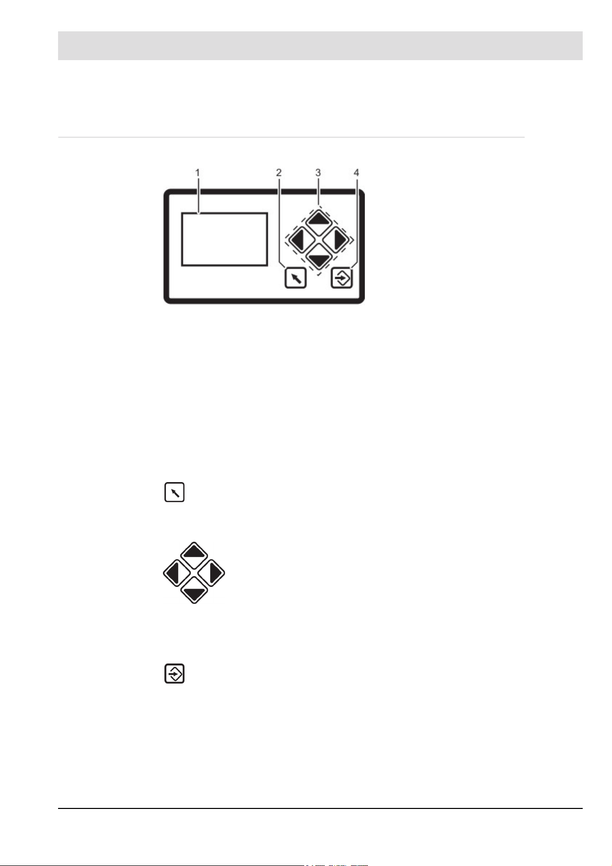
5.1 UI300 User Interface
Fig. 5-1 User Interface
Display
The display shows in pictograms:
• the menu structure
• operating status
• parameters
• error messages
1 Display
2 BACK key
3 Cursor keys
4 ENTER key
Back key
Jump to previous window.
Cursor keys
ENTER keys
Press ENTER to call up a menu on the start screen. Select a sub-menu in the menu
window. Transfer setting values by pressing ENTER key in a parameter window.
You navigate in the menu using cursor keys.
You use "left'' and ''right'' keys to move step by step in a selected row. At
the end of the selected row the cursor jumps down to the next row, if possible.
In a multiline menu use "up" and "down" keys to switch to other rows.
To display parameters, switch between various fields.
14
Page 16

5 Operating Control and Displays
5.2 Menu Functions
The menu is divided into three paths:
INFO
MANUAL
SETTINGS
INFO
Select INFO path for information about the following:
• Burner
• Faults/Fault history
• Software version
• Display of check sums
• Serial number
• Actuator positions (current damper position for each channel)
• Digital inputs/outputs
MANUAL
Select MANUAL to:
• start and stop burner by hand
• adjust internal burner firing-rate
SETTINGS
Select the SETTINGS path for getting information/make changes to:
• Password
• Burner settings (display and settings)
• Actuator elements settings (display)
• Air/fuel control system
• Deletion of curve sets
• Display settings
15
Page 17

5 Operating Control and Displays
5.3 Main Menu
Fig. 5-2 Main menu
1. Use cursor keys to select a menu and press ENTER to confirm.
5.4 Information Menu Path
1 INFORMATION menu path [selected]
2 Display of fuel type
3 Bar graph of internal firing-rate in %
(0 - 100)
4 MANUAL menu path
5 Access level 2
6 SETTINGS menu path
7 Window number
1. Use cursor keys to select path and press ENTER to confirm.
The display shows a menu overview.
5.4.1 Burner Details
Display operating hours
1. Use cursor keys to select menu and press ENTER to confirm.
1 Burner information [selected]
2 Serial number
3 Fault history
4 Configuration of actual value of actuating
outputs (display only)
5 Software version
6 Digital inputs/outputs
7 Check sum display
Fig. 5-3 Display Menu overview
The display shows the "System Information" menu window.
Fig. 5-4 Display "System information"
16
1 Display operating hours [selected]
2 No. of burner start-ups
Page 18

5 Operating Control and Displays
2. Use keys to select menu and press ENTER to confirm.
The display shows the "Display operating hours" menu window.
Fig. 5-5 Display "Operating hours"
Display burner start-ups
1. Use keys in System Information menu to select menu and press ENTER
to confirm.
The display shows the "Start-up counter" menu window.
1 Pictogram operating hours
2 Total number of operating hours
(device connected to mains voltage)
3 No. of operating hours, oil operation
4 No. of operating hours, gas operation
Fig. 5-6 Display "Start-up counter"
5.4.2 Recall Fault History
Display burner faults
1. Use cursor keys to select menu and press ENTER to confirm.
The display shows "Fault history selection" menu.
1 Pictogram burner start-up
2 No. of burner start-ups, oil operation
3 No. of burner start-ups, gas operation
1 Burner fault pictogram [selected]
Fig. 5-7 Fault history selection menu
2. Use keys to select menu and press ENTER to confirm.
The display shows "Fault history" menu.
17
Page 19

5 Operating Control and Displays
Fig. 5-8 Fault history menu
NOTICE!
Information concerning fault and diagnostic codes you may find in the list of fault codes.
For fault analysis a fault code and diagnostic code D1 or D2 is required.
5.4.3 Software Version
1 Error code-display pictogram
2 Fault code (Last 10 faults are stored,
no. 01 is the latest fault)
3 Diagnostic code 1
4 Diagnostic code 2
5 No. of operating hours when fault has oc-
cured
Display software version
1. Use cursor keys to select menu and press ENTER to confirm.
The display shows the "Software version" menu.
1 Software version pictogram
2 UI300 software version (User Interface)
3 BT300 software version (BurnerTronic)
Fig. 5-9 Software version menu
18
Page 20

5 Operating Control and Displays
5.4.4 Display of Check Sums
Display check sum
1. Use cursor keys to select menu and press ENTER to confirm.
The display shows "CRC16 check sums" menu.
Fig. 5-10 CRC16 check sums menu
5.4.5 Serial Number
1 Check sums pictogram
2 Check sum, access level 0
3 Check sum, access level 1
4 Check sum, access level 2
5 Check sum, access level 4
Display serial number
1. Use cursor keys to select menu and press ENTER to confirm.
The display shows the "Serial number" menu.
1 Serial number pictogram
2 User Interface serial number
3 BurnerTronic serial number
Fig. 5-11 Serial number menu
19
Page 21

5 Operating Control and Displays
5.4.6 Positions of Actuators
Display positions of actuators
1. Use the cursor keys to select menu and press ENTER to confirm.
The display shows the "Actuators" menu.
Fig. 5-12 Actuators menu
1 Actuator pictogram
2 Actuator channel 1 (oil)
3 Actuator channel 2 (air)
4 Actuator channel 3 (oil)
5 Optional channel (OFF;
control of frequency converter)
6 Actuator’s actual position
NOTICE!
The assignment of channels is depending on configuration settings!
5.4.7 Check Digital Inputs/Outputs
Check digital inputs
1. Use cursor keys to select menu and press ENTER to confirm.
The display shows the "Digital inputs/outputs" menu.
Fig. 5-13 Digital inputs and outputs menu
2. Select menu and press ENTER to confirm.
The display shows the 1st page of inputs":
1 Digital inputs pictogram [selected]
2 Digital outputs pictogram
20
Page 22

5 Operating Control and Displays
Fig. 5-14 Page 1 of inputs menu
NOTICE!
Signals of points 3 and 4 are "logical" signals and not "physical" ones. Background information: Some signals may have more than one source (terminal, LSB, field buses, parameters).
Call up 2nd page of inputs
1. Use cursor keys to select the next page and press ENTER to confirm.
The display shows the 2nd page of inputs:
1 Digital inputs pictogram
2 Jump to next page
3 Fuel selection oil [no]
4 Fuel selection gas [yes]
5 Burner start [yes] - terminal X10
1 Digital inputs pictogram
2 Jump to next page
3 Oil pressure min present [no]
- terminal X05
4 Gas pressure min present [yes]
- terminal X05
5 Air pressure min present [yes]
Fig. 5-15 Page 2 of inputs menu
- terminal X08
Call up 3rd page of inputs
1. Use the cursor keys to select the next page and press ENTER to confirm.
The display shows the 3
rd
page of inputs:
1 Digital inputs pictogram
2 Jump to previous page
3 Jump to next page
4 Safety interlock chain oil closed [no]
- terminal X06
5 Safety interlock chain gas closed [no]
6 Safety interlock chain boiler closed [no]
Fig. 5-16 Page 3 of inputs menu
21
Page 23

5 Operating Control and Displays
NOTICE!
Signals of points 4 and 5 in Fig. 5-15 Page 2 of inputs menu are "logical" signals, not "physical". The BT320/330 supports either oil or gas operation, but cannot be switched. Therefore
no separate signals for the oil or gas safety interlock chain are generated. The signal on terminal X06 is thus generally known as burner‘s safety interlock chain.
Call up 4th page of inputs
1. Use cursor keys to select next page and press ENTER to confirm.
The display shows the 4th page of inputs:
1 Digital inputs pictogram
2 Jump to previous page
3 Flame signal present [no] - terminal X21
4 Fault release [no] - terminal X10
5.4.8 Digital Outputs
Check digital outputs
1. Use the cursor keys to select the menu and press ENTER to confirm.
Fig. 5-17 Page 4 of inputs menu
The display shows "Page 1 digital outputs" menu:
1 Digital outputs pictogram
2 Jump to next page
3 Fan [on] - terminal X25
4 Error [off] - terminal X24
(adjustable with P 809)
5 Ignition transformer [off] - terminal X04
Fig. 5-18 Page 1 digital outputs menu
22
Page 24

5 Operating Control and Displays
Call up 2
nd
page of outputs
1. Use the cursor keys to select the next page and press ENTER to confirm.
The display shows "Page 2 digital outputs" menu:
1 Digital outputs pictogram
2 Jump to previous page
3 Jump to next page
4 Oil valve 1 [on] - terminal X01
5 Oil valve 2 [off] - terminal X02
6 Oil valve 3 [off] - terminal X03
Fig. 5-19 Page 2 digital outputs menu
rd
Call up 3
page of outputs
1. Use the cursor keys to select the next page and press ENTER to confirm.
The display shows "Page 3 digital outputs" menu:
1 Digital outputs pictogram
2 Jump to previous page
3 Jump to next page
4 Ignition valve [on] - terminal X03
5 Gas valve 1 [off] - terminal X01
6 Gas valve 2 [off] - terminal X02
Fig. 5-20 Page 3 digital outputs menu
Call up 4th page of outputs
1. Use the cursor keys to select the next page and press ENTER to confirm.
The display shows "Page 4 digital outputs" menu:
1 Digital outputs pictogram
2 Jump to previous page
3 Oil pump [off] - terminal X26
4 Fuel selection oil [off] - terminal X24
(adjustable with P 809)
5 Fuel selection gas [off] - terminal X24
(adjustable with P 809)
Fig. 5-21 Page 4 digital outputs menu
23
Page 25

5 Operating Control and Displays
5.5 Manual Menu Path
MANUAL
Select MANUAL path to carry out actions as follows:
1 Switching burner ON and OFF
2 Presetting of burner firing-rate
Display MANUAL menu
1. Use cursor keys to select path and press ENTER to confirm.
The display shows the "Manual operation" menu.
1 Pictogram Manual operation
2 Start burner manually [off]
3 Adjust burner firing-rate
4 Pictogram confirm settings
Fig. 5-22 Menu manual operation
The "Burner ON" control loop does not need to be switched on to start the burner from this
menu. The user interface assumes control in this menu.
If there is no "Burner ON" signal from other sources (terminal X10.2) software switches off the
burner when you exit the menu.
CAUTION!
If you carry out a manual start-up via display BT300 no longer responds to "Burner ON" signal
input at connector X10.2. Therefore that limiters, monitors and other similar safety functions
must not be operated with this input!
NOTICE!
Leaving of window will terminate manual burner operation!
Adjust burner firing-rate
1. Use cursor keys to select adjustment of burner firing-rate in % and press ENTER
to confirm .
2. Change burner firing-rate with the cursor keys and press ENTER to confirm.
NOTICE!
Changes of burner firing-rate are possible only while burner is running.
If you want to adjust burner firing-rate remember to start-up the burner first.
24
Page 26

5 Operating Control and Displays
5.6 Settings Menu Path
Display SETTINGS menu
1. Use cursor keys to select menu and press ENTER to confirm.
The display shows the menu overview.
Fig. 5-23 Menu overview
1 Password pictogram (selected)
2 Delete curves
3 Display program settings
4 Firing-rate controller settings
5 Configuration of read-out
actuator outputs
6 Password settings
7 Curve settings
8 Display settings
5.6.1 Enter Password
Display menu password entry
1. Use cursor keys to select menu and press ENTER to confirm.
2. Use the cursor keys to select password field you wish to change.
3. Change the number with cursor keys .
4. Confirm password with ENTER .
The display shows the password entry menu.
1 Password pictogram (selected)
2 Enter password
3 Access level 2 displayed with access au-
thorisation
Fig. 5-24 Enter password menu
25
Page 27

5 Operating Control and Displays
5.6.2 Program Sequence
Configure program sequence
1. Use cursor keys to select menu and press ENTER to confirm.
The display shows the program sequence overview.
Fig. 5-25 Overview program sequence
1 Duration of pre-ventilation [selected]
2 Pilot burner oil operation
3 Duration of post-ventilation
4 Valve leakage test
5 Pilot burner gas operation
Set pre-ventilation period
1. Use cursor keys to select menu and press ENTER to confirm.
The display shows the pre-ventilation period menu.
1
Fig. 5-26 Period of pre-ventilation menu
NOTICE!
Pre-ventilation starts as soon as damper reaches pre-ventilation position and - if you use a
VSM - the last but one point of fuel/air ratio curve is passed.
NOTICE!
The second to last channel’s position must be lower than the position of the last curve point.
2 3
1 Pre-ventilation period pictogram
2 Setting pre-ventilation time
3 Accept value by pressing ENTER
2. Use cursor keys to select the number you want to change.
3. Change the numerical value with cursor keys .
4. Confirm the entry with ENTER .
The countdown starts.
26
Page 28

5 Operating Control and Displays
Fig. 5-27 Secure data transfer
NOTICE!
Apply value only if the values for UI300 and BT300 are identical!
The parameter value must be confirmed by pressing ENTER within the countdown (8 s)!
5. Accept or discard the entry.
1 UI300 pictogram
2 BT300 pictogram
3 Cancel (backwards)
4 Parameter number UI300
5 Parameter number UI300
6 Transfer by pressing ENTER (flashing)
7 Value for UI300
8 Value for BT300
NOTICE!
The following sequence of events for confirming or discarding the entry is exactly the same
for all parameter entries. Therefore this process is not illustrated again in following explanations of parameter settings.
You will simply find this text: "Accept or discard the entry!"
a) Press ENTER in time to confirm.
The value is accepted.
The display shows the following page:
1 Pictogram UI300
2 Pictogram BT300
3 Parameter number UI300
4 Parameter number BT300
5 Pictogram discard parameters
6 Value BT300
7 Value UI300
Fig. 5-28 Display after successful data transfer
The parameter change is transferred to the burner control system!
CAUTION!
If both values are identical you apply the value by pressing ENTER. In case of a discrepancy
of values terminate the storage process.
b) Cancel parameter changes.
Select the Back key .
The change made to the parameter is not accepted.
The following page appears:
27
Page 29

5 Operating Control and Displays
Fig. 5-29 Display of invalid data transfer
Set duration of post-ventilation
1. Use cursor keys to select menu and press ENTER to confirm.
The display shows the post-ventilation period menu.
1 Pictogram UI300
2 Pictogram BT300
3 Parameter number UI300
4 Parameter number BT300
5 Pictogram apply parameters
6 Value BT300
7 Value UI300
1 Post-ventilation period pictogram
2 Setting post-ventilation time
3 Press ENTER to acceppt setting
Fig. 5-30 Post-ventilation period menu
2. Use cursor keys to select number you wish to change.
3. Change the numerical value with cursor keys .
4. Confirm entry with ENTER .
Accept or discard the entry!
Leakage test functions
1. Use cursor keys to select menu and press ENTER to confirm.
The display shows the valve leakage test menu.
1 Leakage test ON/OFF
2 Leakage test before ignition
3 Leakage test after ignition
4 Leakage test period
Fig. 5-31 Leakage test menu
28
Page 30

5 Operating Control and Displays
NOTICE!
You require access level 2 to make settings in this function!
Accept or discard the entry!
Activate valve leakage test prior to ignition
1. Use cursor keys to select menu and press ENTER to confirm.
2. Change the functional state ON/OFF using cursor keys and press ENTER .
The display shows the valve leakage test menu before ignition:
1 Valve leakage test before ignition picto-
gram
2 Display valve leakage test (ON)
3 Press ENTER to accept settings
Fig. 5-32 Valve leakage test prior to ignition menu
The valve leakage test is set!
NOTICE!
You require access level 2 to make settings in this function!
Accept or discard the entry!
Activate valve leakage test after flame OFF
1. Use cursor keys to select menu and press ENTER to confirm.
2. Change the functional state ON/OFF using cursor keys and press ENTER .
The display valve leakage test is shown after flame OFF menu.
1 Valve leakage test after flame OFF picto-
gram
2 Display valve leakage test (ON)
3 Press ENTER to accept settings
Fig. 5-33 Valve leakage test after flame OFF menu
The valve leakage test is set!
NOTICE!
You require access level 2 to make settings in this function!
Accept or discard the entry!
29
Page 31

5 Operating Control and Displays
Valve leakage test period
1. Use cursor keys to select menu and press ENTER to confirm.
The display shows the valve leakage test period menu.
Fig. 5-34 Valve leakage test menu
2. Use cursor keys to select the number you wish to change.
3. Change the numerical value with cursor keys .
4. Press ENTER to confirm.
Accept or discard the entry!
1 Valve leakage test period pictogram
2 Set valve leakage test period
3 Press ENTER to accept settings
Activate pilot burner in gas operation
1. Use cursor keys to select menu and press ENTER to confirm.
2. Change functional state ON/OFF using cursor keys and press ENTER to
confirm.
The display shows the menu: "pilot burner in gas operation".
1 Pilot burner in gas operation pictogram
2 Activate the pilot burner in gas operation
3 Press ENTER to accept settings
Fig. 5-35 Pilot burner in gas operation menu
NOTICE!
You require access level 2 to make settings in this function!
Accept or discard the entry!
Set pilot burner in oil operation
1. Use cursor keys to select menu and press ENTER to confirm.
2. Change functional state ON/OFF using the cursor keys and press ENTER
to confirm.
The display shows the menu: "pilot burner in oil operation".
30
Page 32

5 Operating Control and Displays
Fig. 5-36 Pilot burner in oil operation menu
NOTICE!
You require access level 2 to make settings in this function!
Accept or discard the entry!
Configuration of actuating outputs
1. Use cursor keys to select menu and press ENTER to confirm.
The display shows the configuration of actuating outputs menu.
1 Pilot burner in oil operation pictogram
2 Activate pilot burner in oil operation
3 Press ENTER to accept settings
1 Actuator position pictogram
2 Display channel 1, oil
3 Display channel 2, air
4 Channel active
5 Display channel 3, off
6 Optional channel, off
Fig. 5-37 Configuration of actuating outputs menu
Curve setting of actuators
1. Use cursor keys to select menu and press ENTER to confirm.
NOTICE!
Pressing key and holding it longer than 2 s in this menu will cause a fault shut-down.
The display shows the curve setting menu.
1 Ignition position firing-rate point
2 Setpoint channel 1, oil
3 Actual value channel 1, oil
4 Setpoint channel 2, air
5 Actual value channel 2, air
6 Setpoint channel 3, oil
7 Actual value channel 3, oil
8 Curve data for this firing-rate point
Fig. 5-38 Curve setting menu
already existing
31
Page 33

5 Operating Control and Displays
2. Use cursor keys to set firing-rate point and press ENTER to confirm.
Set-point channel 1 is chosen (displayed inversely).
3. Use cursor keys to set channels’ actuator position.
4. Use cursor keys to switch to next channel.
5. Use cursor keys to set actuators’ position in the selected firing-rate point.
NOTICE!
Actuators move according to changes immediately to the set position.
If you want to change channel 4 the fan motor must be running.
Accept or discard the entry!
The display switches to the firing-rate selection menu.
6. Use BACK key to switch to menu settings after having completed curve settings.
NOTICE!
The following firing-rate points are available:
Ignition point , 200, 250, 300, 400, 500, 600, 700, 800, 900, 999
7. Set your firing-rate points as described above and press ENTER to confirm.
NOTICE!
If you press key while setting firing-rate points your value changes will be discarded.
Set multi-stage oil operation - 1
Fig. 5-39 Multi-stage operation menu
1. Select the first stage and press ENTER .
The actuators move to the pre-set positions.
The setpoint position of the first activated actuator is displayed inversely.
2. Use cursor keys to set the position of the selected actuator.
3. Use cursor keys to switch to a different actuator.
4. Press ENTER .
The positions of all actuators of the selected firing-rate point are saved.
You can select the next firing-rate point.
st
stage
1 Display 1st stage
2 Set-point, air damper position
3 Actual value, air damper position
NOTICE!
If you press the key while changing the firing-rate point your changes will be discarded.
32
Page 34

5 Operating Control and Displays
NOTICE!
During multi-stage operation, the following points are available:
Ignition point ,
1 (first stage),
1 2 (valve switch-on point, second stage),
1 2 (valve switch-off point, second stage)
2 (second level),
2 3 (valve switch-on point, third stage),
2 3 (valve switch-off point, third stage),
3 (third stage)
NOTICE!
Pre-ventilation starts as soon as the damper reaches pre-ventilation position and - if you use
a VSM - the last but one point of the fuel/air ratio curve is passed.
NOTICE!
The points are approached from above by using the overshoot-function. If you use the overshoot-function in operatio, you must program all points from above. Only if you do so, the required position will match the actual position.
NOTICE!
The channels’ position in the last but one curve point must be lower than at the last curve point.
33
Fig. 5-40 3-staged operation
Page 35

5 Operating Control and Displays
Set staged oil operation - transition from 1st to 2nd stage
Fig. 5-41 Transition from 1st to 2nd stage
1. Select the setpoint for the air damper position and press ENTER to confirm.
The actuators move to these positions.
The setpoint position for the active actuator is displayed inversely.
2. Use the cursor keys to set the position of the selected actuator.
3. Use the cursor keys to switch to a different actuator.
4. Press ENTER .
Positions for all actuators of the selected firing-rate point are saved.
You can select the next firing-rate point.
1 Display valve switch-on point, 2nd stage
2 Setpoint, air damper position
3 Actual value, air damper position
NOTICE!
Set the other firing-rate stages according to this procedure!
Delete firing-rate curves
1. In "Settings" menu path use cursor keys to select menu and press ENTER
to confirm.
The display shows the "Deleting curves" menu.
1 Delete curves pictogram
2 Delete curves selected
3 Confirm deleting of curves
Fig. 5-42 Deleting curves menu
34
Page 36

5 Operating Control and Displays
The display shows the confirmation prompt:
Fig. 5-43 Confirmation prompt of deleting curves
menu
2. Press ENTER .
The curve values will be deleted.
The display shows the values deleted menu.
1 Back to previous menu
2 Deleting values [selected]
3 Proceed with deleting values
Fig. 5-44 Values deleted menu
UI300 display settings
Fig. 5-45 Display settings menu
1 Values deleted
1 UI300 pictogram
2 Brightness
3 Contrast
4 Delay for screen saver
NOTICE!
Value= 0 cannot be entered for the screen saver delay!
35
Page 37

5 Operating Control and Displays
5.6.3 Other Displays
No connection between UI300 and BT300
Fig. 5-46 No connection
Display shown e.g. when using LSB remote software and communication between BT300 and
UI300 is temporarily unavailable.
Termination
1 UI300 User Interface pictogram
2 No connection symbol
3 BT300 burner control
Fig. 5-47 Termination
1 Communication error pictogram
connection unavailable
36
Page 38

6 Leakage Test for Main Gas Valves
6 Leakage Test for Main Gas Valves
6.1 Calculation Example
An (approximate) formula for calculating the leakage test monitoring facility is summarised below:
Definitions: GDW: gas pressure monitor
V1: gas-side safety shut-off device
V2: burner-side safety shut-off device
P
B
P
SU
P
SO
p = PSO - PBGDW switching difference
PG gas flow pressure (supply pressure before V1)
V
P
V
L
V
Lmax
t
P
This means for a maximum gas flow rate of 50 m3/h the formula is:
barometric air pressure < 1000 mbar
lower GDW switching point (falling)
upper GDW switching point (rising)
volume of gas line tested
leakage quantity
maximum admissible leakage quantity (limit value)
testing time (30 s adjustable, default = 20 s)
Insert numerical value in mbar for Δp.
The formula for a gas flow rate of Q > 50 m3/h is:
Insert the numerical value in m3/h for Q and in mbar for Δp .
A. Assuming: ∆p = 20 mbar, gas flow rate < 50 m3/h
i.e. the gas line you want to test must not
exceed 20,8 dm3, for being able to detect
the required leakage quantity.
B. Assuming: ∆p = 20 mbar, gas flow rate = 200 m3/h
i.e. the gas line you want to test must not
exceed 83,3 dm, for being able to detect
the required leakage quantity of 200 dm3/h.
37
Page 39

6 Leakage Test for Main Gas Valves
6.2 Leakage Test with Ventilation Via Roof
The leakage test checks whether or not the main gas valves are leakproof. For this purpose
the gas pressure of the supply is analysed.
As leakage test section (space between the two main valves) burns empty whenever the burner is switched off, this part is usually pressureless at start-up (gas pressure > min = 0). This is
checked by BurnerTronic. At this point, main gas 1 opens briefly and gas flows into test section
(gas pressure > min switches from 0 to 1). This pressure must remain constantly at least while
leakage test period (P 311) is running. The leakage test is considered complete then.
If leakage test section is not empty at start-up (e.g. resulting from a previous fault shutdown),
main gas valve 2 opens first. The leakage test line is then ventilated (depending on the plant,
either in the combustion chamber or through the roof – for wiring proposition, see chapter 6.3
Exhaust of Test Line Over the Roof). During leakage test period section is checked whether
it remains pressureless or not. Apart from that the process is the same as described above.
The leakage test takes place prior to ignition.
You must connect the pressure monitor for the leakage test line at the “Gas pressure > min”
input on plug X05. It also monitors the minimum pressure during operation. If a different minimum pressure should be monitored during operation, the pressure monitor must be inserted
into the safety interlock chain gas or into the controller loop (burner ON). You must assure by
dimensioning the gas line in a way that leakage test control time is sufficient for detecting reliably a burner gas consumption leakage of 0.1%, but at least 50 dm3/h (at maximum combustion heat output).
NOTICE!
You may only vent 0.05 % of fuel consumption at maximum firing-rate into combustion chamber.
38
Page 40

6 Leakage Test for Main Gas Valves
Fig. 6-1 Leakage test process diagram
39
Page 41

6 Leakage Test for Main Gas Valves
6.3 Exhaust of Test Line Over the Roof
NOTICE!
Consider diameter of gas line in the roof ventilation. For ventilation, plug X02 is activated for
3 s. Make sure that this period is sufficient even for smallest ventilation line diameter!
Fig. 6-2 Wiring proposition for ventilation of gas line via roof in combination with BurnerTronic
40
Page 42

7 Technical Data
7 Technical Data
7.1 Technical Data BT300
Function
Power supply: 230 V +10/-15 % 47-63 Hz
115 V +10/-15 % 47-63 Hz (on request)
Maximum backup-fuse: 10 A slow-blow
To be used only in a grounded power line network!
Power consumption: max. 30 VA
Switching threshold of ionisation
current:
Digital signal inputs: Max. line length 10 m
Digital outputs: 3 fuel valves max. 1 A cos 0,4
Resolution: 999 digit, 10 bit
Number of curve sets: BT320/33x: 1 curve set (oil or gas)
Number of programs: unlimited (EEPROM)
Field bus-coupling (optional): PROFIBUS
Housing: Polycarbonate + ABS
Dimensions: 200x115x61 mm
Weight: 1,0 kg
Flammability: UL-94 V0 (panel: UL-94 V2)
1 A
VL fan max. 2 A cos 0,4
oil pump max. 2 A cos 0,4
ignition transformer max. 2 A cos 0,2
alarm output max. 1 A cos 0,3
BT34x: 2 curve sets (oil/gas switchable; DFM300 or LCM100 required)
LCM100 always required
Display
Display: 128x64 pixel, monochrome
White backlighting (dimmable)
Dimensions: 112 x 64 x 24 mm
Weight: 140 g
Housing: Basic housing: Polyamide glass fibre reinforced
LCD-display window: Polycarbonate
Flammability: Basic housing UL-94 V0
LCD-display window UL-94 V2
Environmental Conditions
Operation: Climatic conditions Class 3K5 according to DIN EN 60721-3
Mechanic conditions Class 3M5 according to DIN EN 60721-3
Temperature range -20 ... +60 °C (condensation is prohibited)
Transport: Climatic conditions Class 2K3 according to DIN EN 60721-3
Mechanic conditions Class 2M2 according to DIN EN 60721-3
Temperature range -20 ... +70 °C (condensation is prohibited)
41
Page 43

7 Technical Data
Environmental Conditions
Storage: Climatic conditions Class 1K3 according to DIN EN 60721-3
Mechanic conditions Class 1M2 according to DIN EN 60721-3
Temperature range -20 ... +70 °C (no condensation)
Electronic safety: Degree of protection (DIN EN 60529): BT300 – IP40 housing
IP20 terminals
UI300 – IP40 (clamping)
IP54 (glued assembly)
7.2 Actuators 662R550...
Function
Floating time 5 s / 90° at 180 Hz
Direction of rotation 0° to 90° right
Torque 0.8 Nm (both directions)
Holding torque 0.4 Nm (no power)
0.7 Nm
Permissible radial load 30 Nm (centre of output shaft)
Permissible axial load 5 N
Axial play of drive shaft 0.1 ... 0.2 mm
Environmental conditions
Operation Climatic condition Class 3K3 according to DIN EN 60721-3
Mechanical condition Class 3M3 according to DIN EN 60721-3
Temperature range -20 ... +60 °C (condensation is prohibited)
Transport Climatic condition Class 2K3 according to DIN EN 60721-3
Mechanical condition Class 2M2 according to DIN EN 60721-3
Temperature range -20 ... +70 °C (condensation is prohibited)
Storage Climatic condition Class 1K3 according to DIN EN 60721-3
Mechanical condition Class 1M2 according to DIN EN 60721-3
Temperature range -20 ... +70 °C (condensation is prohibited)
Bursting strength Peak voltage 4 kV
Repeat frequency 2,5 kHz
Electrical safety Protection class 2 as per DIN EN 60730
DANGER!
Danger by electrical shock!
If you don’t shut BurnerTronic down befor opening the cover, you may get in contact with conducting parts. This may cause an electrical shock. You may open BurnerTronic only if you
have disconnected it all-pole.
Disconnect BurnerTronic all-pole.
42
Page 44

7 Technical Data
NOTICE!
Damaging the 0,8 Nm actuator by opening the actuator.
If you open the actuator at another part as the cover of the electric connection, you will damage the actuator.
Do not open the actuator but at the cover of the electric connection.
7.3 Actuators 662R5001... / 662R5003...
Function 662R5001... 662R5003... 662R5009...
Floating time 5 s/90° 5 s/90° 15 s/90°
Direction of rotation 0°
to 90°
Effective
output torque
Holding torque 0.82 Nm (currentless) 2.8 Nm (currentless) 6 Nm (currentless)
Permissible
radial load
Permissible axial load 10 N
Axial play of drive shaft 0.1 ... 0.2 mm 0.1 ... 0.2 mm
Motor RDM 51/6 stepper motor
Angular resolution 0.1°/motor step 0.1°/motor step 0.03°/motor step
Rated resolution
encoder monitoring
Monitoring
accuracy
Repeat accuracy 0,1° 0,1° 0,1°
Life cycle 2,000,000 motions forward and back performed on complete actuator range
Degree of protection IP54 according to DIN EN 60529-1
Weight 1400 g
left - view to the drive shaft
1.2 Nm
(both directions of rotation)
100 N (centre of output shaft)
0,7°
0,5° 0,5° 1,3125 (is equal to 44
3 Nm
(both directions of rotation)
9 Nm
(both directions of rotation)
motor steps)
Environmental conditions 662R5001.../662R5003.../662R5009...
Operation Climatic condition Class 3K5 according to DIN EN 60721-3
Mechanical condition Class 3M5 according to DIN EN 60721-3
Temperature range -20 ... +60 °C (condensation is prohibited)
Transport Climatic condition Class 2K3 according to DIN EN 60721-3
Mechanical condition Class 2M2 according to DIN EN 60721-3
Temperature range -20 ... +70 °C (condensation is prohibited)
Storage Climatic condition Class 1K3 according to DIN EN 60721-3
Mechanical condition Class 1M2 according to DIN EN 60721-3
Temperature range -20 ... +70 °C (condensation is prohibited)
Bursting strength Peak voltage 4 kV
43
Page 45

7 Technical Data
Environmental conditions 662R5001.../662R5003.../662R5009...
Repeat frequency 2,5 kHz
Electrical safety Protection class 2 as per DIN EN 60730
NOTICE!
Damage of the actuator due to opening the actuators housing.
You will damage the actuator, if you open the actuator’s housing at another (this affects actuators with 1,2, 3,0 and 9,0 Nm).
44
Page 46

7 Technical Data
45
Page 47

Page 48

The information in this publication is subject to technical changes.
DLT1206-13-aEN-008
Copyright© 2011 LAMTEC
LAMTEC Meß- und Regeltechnik
für Feuerungen GmbH & Co. KG
Wiesenstraße 6
D-69190 Walldorf
Phone: +49 (0) 6227 / 6052-0
Fax: +49 (0) 6227 / 6052-57
e-mail:info@lamtec.de
www.lamtec.de
LAMTEC Leipzig GmbH & Co. KG
Portitzer Straße 69
D-04425 Taucha
Phone: +49 (0) 34298 / 4875-0
Fax: +49 (0) 34298 / 4875-99
Presented by:
Print no. DLT1206-13-aEN-008
Printed in Germany
 Loading...