

Page 1

Manual
BT300 BurnerTronic
Sensors and Systems for Combustion Engineering
www.lamtec.de
Page 2

Page 3

Table of Contents
Table of Contents
1 Important Information about the Manual . . . . . . . . . . . . . . . . . . . . . . . . . . . . . . . . . . . . . . . . 6
1.1 Validity of these Instructions. . . . . . . . . . . . . . . . . . . . . . . . . . . . . . . . . . . . . . . . . . . . . . . 6
1.2 Standards, Directives and Approvals. . . . . . . . . . . . . . . . . . . . . . . . . . . . . . . . . . . . . . . . 6
2 General Safety Instructions . . . . . . . . . . . . . . . . . . . . . . . . . . . . . . . . . . . . . . . . . . . . . . . . . . 8
2.1 Classification of the Safety Instructions and Warnings . . . . . . . . . . . . . . . . . . . . . . . . . . 8
2.2 Product-specific Dangers. . . . . . . . . . . . . . . . . . . . . . . . . . . . . . . . . . . . . . . . . . . . . . . . . 9
2.2.1 Commissioning Notes . . . . . . . . . . . . . . . . . . . . . . . . . . . . . . . . . . . . . . . . . . . . 10
2.2.1.1 Fuel/Air Ratio Control . . . . . . . . . . . . . . . . . . . . . . . . . . . . . . . . . . . . . . . . . . . . 10
2.2.1.2 Basic Device . . . . . . . . . . . . . . . . . . . . . . . . . . . . . . . . . . . . . . . . . . . . . . . . . . . 11
2.2.2 Tasks fulfilled by "authority on the subject" during Approval Test . . . . . . . . . . . 11
2.2.2.1 Checking for Correct Parameter Setting in System . . . . . . . . . . . . . . . . . . . . . . 11
2.2.2.2 Checking the Fuel/Air Ratio Control System . . . . . . . . . . . . . . . . . . . . . . . . . . . 12
2.2.2.3 Checking Burner Sequencer Part . . . . . . . . . . . . . . . . . . . . . . . . . . . . . . . . . . . 12
2.3 Security Advice - Mounting . . . . . . . . . . . . . . . . . . . . . . . . . . . . . . . . . . . . . . . . . . . . . . 12
2.4 Installation Notes . . . . . . . . . . . . . . . . . . . . . . . . . . . . . . . . . . . . . . . . . . . . . . . . . . . . . . 13
2.5 Electrical Connection Flame Sensor . . . . . . . . . . . . . . . . . . . . . . . . . . . . . . . . . . . . . . . 13
3 Product Description. . . . . . . . . . . . . . . . . . . . . . . . . . . . . . . . . . . . . . . . . . . . . . . . . . . . . . . . 15
3.1 Functional Description . . . . . . . . . . . . . . . . . . . . . . . . . . . . . . . . . . . . . . . . . . . . . . . . . . 15
3.2 Life Cycle . . . . . . . . . . . . . . . . . . . . . . . . . . . . . . . . . . . . . . . . . . . . . . . . . . . . . . . . . . . . 16
3.3 Technical Data . . . . . . . . . . . . . . . . . . . . . . . . . . . . . . . . . . . . . . . . . . . . . . . . . . . . . . . . 16
3.3.1 BT300 . . . . . . . . . . . . . . . . . . . . . . . . . . . . . . . . . . . . . . . . . . . . . . . . . . . . . . . . 16
3.3.2 Actuator . . . . . . . . . . . . . . . . . . . . . . . . . . . . . . . . . . . . . . . . . . . . . . . . . . . . . . . 20
3.3.2.1 Actuators 662R550... . . . . . . . . . . . . . . . . . . . . . . . . . . . . . . . . . . . . . . . . . . . . . 20
3.3.2.2 Actuators 662R5001... / 662R5003... . . . . . . . . . . . . . . . . . . . . . . . . . . . . . . . . 22
3.3.3 Flame Sensor/Flame Scanner . . . . . . . . . . . . . . . . . . . . . . . . . . . . . . . . . . . . . . 26
4 Mounting and Functions . . . . . . . . . . . . . . . . . . . . . . . . . . . . . . . . . . . . . . . . . . . . . . . . . . . . 28
4.1 System Overview . . . . . . . . . . . . . . . . . . . . . . . . . . . . . . . . . . . . . . . . . . . . . . . . . . . . . . 28
4.2 Connecting Diagrams . . . . . . . . . . . . . . . . . . . . . . . . . . . . . . . . . . . . . . . . . . . . . . . . . . 29
4.2.1 Optional Connections for the Fuel Line . . . . . . . . . . . . . . . . . . . . . . . . . . . . . . . 30
4.2.2 Optional Connections for the Flame Scanner . . . . . . . . . . . . . . . . . . . . . . . . . . 31
4.2.3 LSB Module Integration . . . . . . . . . . . . . . . . . . . . . . . . . . . . . . . . . . . . . . . . . . . 34
4.3 Flame Monitoring . . . . . . . . . . . . . . . . . . . . . . . . . . . . . . . . . . . . . . . . . . . . . . . . . . . . . . 36
4.3.1 Integral Flame Monitoring (Option) . . . . . . . . . . . . . . . . . . . . . . . . . . . . . . . . . . 36
4.3.2 Flame Sensors. . . . . . . . . . . . . . . . . . . . . . . . . . . . . . . . . . . . . . . . . . . . . . . . . . 37
4.3.2.1 KLC 20/KLC 2002 . . . . . . . . . . . . . . . . . . . . . . . . . . . . . . . . . . . . . . . . . . . . . . . 37
4.3.2.2 KLC 10/KLC 1000 . . . . . . . . . . . . . . . . . . . . . . . . . . . . . . . . . . . . . . . . . . . . . . . 39
4.4 Process Sequence Charts . . . . . . . . . . . . . . . . . . . . . . . . . . . . . . . . . . . . . . . . . . . . . . . 41
4.5 Leakage Test for Main Gas Valves. . . . . . . . . . . . . . . . . . . . . . . . . . . . . . . . . . . . . . . . . 46
4.5.1 Calculation Example . . . . . . . . . . . . . . . . . . . . . . . . . . . . . . . . . . . . . . . . . . . . . 46
4.5.2 Leakage Test Process Flow. . . . . . . . . . . . . . . . . . . . . . . . . . . . . . . . . . . . . . . . 49
4.5.3 Reaction on Gas Deficiency . . . . . . . . . . . . . . . . . . . . . . . . . . . . . . . . . . . . . . . 51
4.5.4 Valve Leakage Test Venting Over the Roof . . . . . . . . . . . . . . . . . . . . . . . . . . . . 51
4.6 Staged Operation. . . . . . . . . . . . . . . . . . . . . . . . . . . . . . . . . . . . . . . . . . . . . . . . . . . . . . 52
4.7 Flue Gas Recirculation. . . . . . . . . . . . . . . . . . . . . . . . . . . . . . . . . . . . . . . . . . . . . . . . . . 54
4.8 Actuator . . . . . . . . . . . . . . . . . . . . . . . . . . . . . . . . . . . . . . . . . . . . . . . . . . . . . . . . . . . . . 55
4.8.1 Operation after Power ON/Long RESET . . . . . . . . . . . . . . . . . . . . . . . . . . . . . . 55
2
Page 4

Table of Contents
4.8.2 Direction of Rotation/Position Damper Closed . . . . . . . . . . . . . . . . . . . . . . . . . 55
4.8.3 Detection of Actuators with Transposed Connections . . . . . . . . . . . . . . . . . . . . 56
4.8.4 Adjusting of Actuators . . . . . . . . . . . . . . . . . . . . . . . . . . . . . . . . . . . . . . . . . . . . 56
5 Operating Control and Displays . . . . . . . . . . . . . . . . . . . . . . . . . . . . . . . . . . . . . . . . . . . . . . 58
5.1 User Interface UI300 . . . . . . . . . . . . . . . . . . . . . . . . . . . . . . . . . . . . . . . . . . . . . . . . . . . 58
5.1.1 UI300 User Interface . . . . . . . . . . . . . . . . . . . . . . . . . . . . . . . . . . . . . . . . . . . . . 58
5.1.2 Menu Functions . . . . . . . . . . . . . . . . . . . . . . . . . . . . . . . . . . . . . . . . . . . . . . . . . 58
5.1.3 Main Menu . . . . . . . . . . . . . . . . . . . . . . . . . . . . . . . . . . . . . . . . . . . . . . . . . . . . . 60
5.1.4 Information Menu Path . . . . . . . . . . . . . . . . . . . . . . . . . . . . . . . . . . . . . . . . . . . 60
5.1.4.1 Burner Details . . . . . . . . . . . . . . . . . . . . . . . . . . . . . . . . . . . . . . . . . . . . . . . . . . 61
5.1.4.2 Recalling Fault History . . . . . . . . . . . . . . . . . . . . . . . . . . . . . . . . . . . . . . . . . . . . 62
5.1.4.3 Software Version . . . . . . . . . . . . . . . . . . . . . . . . . . . . . . . . . . . . . . . . . . . . . . . . 63
5.1.4.4 Display of Check Sums . . . . . . . . . . . . . . . . . . . . . . . . . . . . . . . . . . . . . . . . . . . 63
5.1.4.5 Serial Number . . . . . . . . . . . . . . . . . . . . . . . . . . . . . . . . . . . . . . . . . . . . . . . . . . 64
5.1.4.6 Positions of Actuators . . . . . . . . . . . . . . . . . . . . . . . . . . . . . . . . . . . . . . . . . . . . 64
5.1.4.7 Check Digital Inputs/Outputs . . . . . . . . . . . . . . . . . . . . . . . . . . . . . . . . . . . . . . . 65
5.1.5 Manual Menu Path. . . . . . . . . . . . . . . . . . . . . . . . . . . . . . . . . . . . . . . . . . . . . . . 66
5.1.6 Fault Indication . . . . . . . . . . . . . . . . . . . . . . . . . . . . . . . . . . . . . . . . . . . . . . . . . 67
5.1.7 Settings Menu Path . . . . . . . . . . . . . . . . . . . . . . . . . . . . . . . . . . . . . . . . . . . . . . 68
5.1.7.1 Password . . . . . . . . . . . . . . . . . . . . . . . . . . . . . . . . . . . . . . . . . . . . . . . . . . . . . . 69
5.1.7.2 Program Sequence . . . . . . . . . . . . . . . . . . . . . . . . . . . . . . . . . . . . . . . . . . . . . . 69
5.1.7.3 Configuration of the Actuators . . . . . . . . . . . . . . . . . . . . . . . . . . . . . . . . . . . . . . 75
5.1.7.4 Set Curve . . . . . . . . . . . . . . . . . . . . . . . . . . . . . . . . . . . . . . . . . . . . . . . . . . . . . . 75
5.1.7.5 Deleting Curves . . . . . . . . . . . . . . . . . . . . . . . . . . . . . . . . . . . . . . . . . . . . . . . . . 76
5.1.7.6 Adjusting Controller . . . . . . . . . . . . . . . . . . . . . . . . . . . . . . . . . . . . . . . . . . . . . . 76
5.1.7.7 UI300 Settings . . . . . . . . . . . . . . . . . . . . . . . . . . . . . . . . . . . . . . . . . . . . . . . . . . 78
5.1.7.8 Edit Parameter . . . . . . . . . . . . . . . . . . . . . . . . . . . . . . . . . . . . . . . . . . . . . . . . . . 78
5.1.8 Menu Path Dataset Processing . . . . . . . . . . . . . . . . . . . . . . . . . . . . . . . . . . . . . 79
5.2 Other Displays . . . . . . . . . . . . . . . . . . . . . . . . . . . . . . . . . . . . . . . . . . . . . . . . . . . . . . . . 80
5.3 LSB Remote Software . . . . . . . . . . . . . . . . . . . . . . . . . . . . . . . . . . . . . . . . . . . . . . . . . . 82
5.3.1 Functional Description, Connecting USB-CAN Module . . . . . . . . . . . . . . . . . . . 82
5.3.1.1 Installation Prerequisites . . . . . . . . . . . . . . . . . . . . . . . . . . . . . . . . . . . . . . . . . . 82
5.3.1.2 Install Software . . . . . . . . . . . . . . . . . . . . . . . . . . . . . . . . . . . . . . . . . . . . . . . . . 83
5.3.1.3 Install Software . . . . . . . . . . . . . . . . . . . . . . . . . . . . . . . . . . . . . . . . . . . . . . . . . 83
5.3.1.4 First Connection with the End Device . . . . . . . . . . . . . . . . . . . . . . . . . . . . . . . . 96
5.3.1.5 Release Codes/Release Levels. . . . . . . . . . . . . . . . . . . . . . . . . . . . . . . . . . . . . 98
5.3.2 Offline/Online . . . . . . . . . . . . . . . . . . . . . . . . . . . . . . . . . . . . . . . . . . . . . . . . . . . 99
5.3.2.1 Offline Mode . . . . . . . . . . . . . . . . . . . . . . . . . . . . . . . . . . . . . . . . . . . . . . . . . . . 99
5.3.2.2 Online Mode . . . . . . . . . . . . . . . . . . . . . . . . . . . . . . . . . . . . . . . . . . . . . . . . . . 100
5.3.2.3 Connecting the BT 300 with the PC. . . . . . . . . . . . . . . . . . . . . . . . . . . . . . . . . 100
5.3.3 Read Out Faults. . . . . . . . . . . . . . . . . . . . . . . . . . . . . . . . . . . . . . . . . . . . . . . . 108
5.3.4 BT300 Curve Dialogue . . . . . . . . . . . . . . . . . . . . . . . . . . . . . . . . . . . . . . . . . . 111
5.3.4.1 Setpoint Graphic . . . . . . . . . . . . . . . . . . . . . . . . . . . . . . . . . . . . . . . . . . . . . . . 112
5.3.4.2 Curve Table . . . . . . . . . . . . . . . . . . . . . . . . . . . . . . . . . . . . . . . . . . . . . . . . . . . 112
5.3.4.3 Set Curve . . . . . . . . . . . . . . . . . . . . . . . . . . . . . . . . . . . . . . . . . . . . . . . . . . . . . 113
5.3.5 Programming of Fuel/Air Ratio Control . . . . . . . . . . . . . . . . . . . . . . . . . . . . . . 115
5.3.6 Programming a Staged Operation . . . . . . . . . . . . . . . . . . . . . . . . . . . . . . . . . . 121
5.3.7 Software Interface LSB Remote Software . . . . . . . . . . . . . . . . . . . . . . . . . . . . 125
5.3.7.1 File . . . . . . . . . . . . . . . . . . . . . . . . . . . . . . . . . . . . . . . . . . . . . . . . . . . . . . . . . . 125
3
Page 5

Table of Contents
5.3.7.2 Access Rights . . . . . . . . . . . . . . . . . . . . . . . . . . . . . . . . . . . . . . . . . . . . . . . . . 130
5.3.7.3 BurnerTronic . . . . . . . . . . . . . . . . . . . . . . . . . . . . . . . . . . . . . . . . . . . . . . . . . . 131
5.3.7.4 Options . . . . . . . . . . . . . . . . . . . . . . . . . . . . . . . . . . . . . . . . . . . . . . . . . . . . . . 134
5.3.7.5 Help . . . . . . . . . . . . . . . . . . . . . . . . . . . . . . . . . . . . . . . . . . . . . . . . . . . . . . . . . 137
6 Maintenance . . . . . . . . . . . . . . . . . . . . . . . . . . . . . . . . . . . . . . . . . . . . . . . . . . . . . . . . . . . . . 139
6.1 BT300 Data Back-Up . . . . . . . . . . . . . . . . . . . . . . . . . . . . . . . . . . . . . . . . . . . . . . . . . . 139
6.2 Firmware Update BT300 . . . . . . . . . . . . . . . . . . . . . . . . . . . . . . . . . . . . . . . . . . . . . . . 140
6.3 Firmware Update UI300. . . . . . . . . . . . . . . . . . . . . . . . . . . . . . . . . . . . . . . . . . . . . . . . 143
6.4 Replacing of BurnerTronic . . . . . . . . . . . . . . . . . . . . . . . . . . . . . . . . . . . . . . . . . . . . . . 144
7 Options . . . . . . . . . . . . . . . . . . . . . . . . . . . . . . . . . . . . . . . . . . . . . . . . . . . . . . . . . . . . . . . . . 145
7.1 Firing-Rate Controller Module LCM100 . . . . . . . . . . . . . . . . . . . . . . . . . . . . . . . . . . . . 145
7.1.1 Range Limits . . . . . . . . . . . . . . . . . . . . . . . . . . . . . . . . . . . . . . . . . . . . . . . . . . 146
7.1.2 Enter Setpoint of Firing Rate Controller. . . . . . . . . . . . . . . . . . . . . . . . . . . . . . 147
7.1.3 Operating Description . . . . . . . . . . . . . . . . . . . . . . . . . . . . . . . . . . . . . . . . . . . 148
7.1.4 Control by atmospheric conditions and external setpoint presetting . . . . . . . . 148
7.1.5 Setpoint Changeover . . . . . . . . . . . . . . . . . . . . . . . . . . . . . . . . . . . . . . . . . . . . 149
7.1.6 Start-up Sequence. . . . . . . . . . . . . . . . . . . . . . . . . . . . . . . . . . . . . . . . . . . . . . 150
7.1.7 Thermostat and Control Range . . . . . . . . . . . . . . . . . . . . . . . . . . . . . . . . . . . . 150
7.1.8 Control Range . . . . . . . . . . . . . . . . . . . . . . . . . . . . . . . . . . . . . . . . . . . . . . . . . 151
7.1.9 Checking the Safety Limiter. . . . . . . . . . . . . . . . . . . . . . . . . . . . . . . . . . . . . . . 151
7.1.10 Control Mode . . . . . . . . . . . . . . . . . . . . . . . . . . . . . . . . . . . . . . . . . . . . . . . . . . 151
7.1.11 Aides for Setting . . . . . . . . . . . . . . . . . . . . . . . . . . . . . . . . . . . . . . . . . . . . . . . 152
7.1.12 External/Manual Firing-rate Presetting (Terminals 16 - 19) . . . . . . . . . . . . . . . 154
7.1.13 DIP Switch . . . . . . . . . . . . . . . . . . . . . . . . . . . . . . . . . . . . . . . . . . . . . . . . . . . . 154
7.1.14 LEDs . . . . . . . . . . . . . . . . . . . . . . . . . . . . . . . . . . . . . . . . . . . . . . . . . . . . . . . . 155
7.1.15 Electrical Connection . . . . . . . . . . . . . . . . . . . . . . . . . . . . . . . . . . . . . . . . . . . . 156
7.1.15.1 Galvanic Isolation. . . . . . . . . . . . . . . . . . . . . . . . . . . . . . . . . . . . . . . . . . . . . . 158
7.1.15.2 Terminal Assignment . . . . . . . . . . . . . . . . . . . . . . . . . . . . . . . . . . . . . . . . . . . 159
7.1.16 Technical data LCM100 . . . . . . . . . . . . . . . . . . . . . . . . . . . . . . . . . . . . . . . . . . 163
7.2 Dual Fuel Module DFM300 . . . . . . . . . . . . . . . . . . . . . . . . . . . . . . . . . . . . . . . . . . . . . 165
7.2.1 DIP Switch . . . . . . . . . . . . . . . . . . . . . . . . . . . . . . . . . . . . . . . . . . . . . . . . . . . . 166
7.2.2 LEDs . . . . . . . . . . . . . . . . . . . . . . . . . . . . . . . . . . . . . . . . . . . . . . . . . . . . . . . . 168
7.2.3 Electrical Connection . . . . . . . . . . . . . . . . . . . . . . . . . . . . . . . . . . . . . . . . . . . . 169
7.2.3.1 Galvanic Isolation . . . . . . . . . . . . . . . . . . . . . . . . . . . . . . . . . . . . . . . . . . . . . . 170
7.2.3.2 Terminal Assignment . . . . . . . . . . . . . . . . . . . . . . . . . . . . . . . . . . . . . . . . . . . . 171
7.2.4 Technical Data DFM300 . . . . . . . . . . . . . . . . . . . . . . . . . . . . . . . . . . . . . . . . . 173
7.2.5 Adapter System Rast5. . . . . . . . . . . . . . . . . . . . . . . . . . . . . . . . . . . . . . . . . . . 174
7.2.5.1 Electrical Connection . . . . . . . . . . . . . . . . . . . . . . . . . . . . . . . . . . . . . . . . . . . . 174
7.2.5.2 Technical Data Rast5-Module . . . . . . . . . . . . . . . . . . . . . . . . . . . . . . . . . . . . . 177
7.3 Variable Speed Drive Module VSM100 . . . . . . . . . . . . . . . . . . . . . . . . . . . . . . . . . . . . 178
7.3.1 DIP Switch . . . . . . . . . . . . . . . . . . . . . . . . . . . . . . . . . . . . . . . . . . . . . . . . . . . . 179
7.3.2 LEDs . . . . . . . . . . . . . . . . . . . . . . . . . . . . . . . . . . . . . . . . . . . . . . . . . . . . . . . . 181
7.3.3 Electrical Connection . . . . . . . . . . . . . . . . . . . . . . . . . . . . . . . . . . . . . . . . . . . . 182
7.3.3.1 Galvanic Isolation . . . . . . . . . . . . . . . . . . . . . . . . . . . . . . . . . . . . . . . . . . . . . . 183
7.3.3.2 Terminal Assignment . . . . . . . . . . . . . . . . . . . . . . . . . . . . . . . . . . . . . . . . . . . . 183
7.3.4 Technical Data VSM100 . . . . . . . . . . . . . . . . . . . . . . . . . . . . . . . . . . . . . . . . . 185
7.4 Expansion Module for LSB - LEM100 . . . . . . . . . . . . . . . . . . . . . . . . . . . . . . . . . . . . . 186
7.4.1 DIP Switch . . . . . . . . . . . . . . . . . . . . . . . . . . . . . . . . . . . . . . . . . . . . . . . . . . . . 186
4
Page 6

Table of Contents
7.4.2 LEDs . . . . . . . . . . . . . . . . . . . . . . . . . . . . . . . . . . . . . . . . . . . . . . . . . . . . . . . . 186
7.4.3 Electrical Connection . . . . . . . . . . . . . . . . . . . . . . . . . . . . . . . . . . . . . . . . . . . . 187
7.4.3.1 Galvanic Isolation . . . . . . . . . . . . . . . . . . . . . . . . . . . . . . . . . . . . . . . . . . . . . . 188
7.4.4 Technical Data LEM300. . . . . . . . . . . . . . . . . . . . . . . . . . . . . . . . . . . . . . . . . . 188
7.5 Field Bus Modules . . . . . . . . . . . . . . . . . . . . . . . . . . . . . . . . . . . . . . . . . . . . . . . . . . . . 189
7.5.1 Field Bus Module for PROFIBUS PBM100 . . . . . . . . . . . . . . . . . . . . . . . . . . . 189
7.5.1.1 DIP Switch . . . . . . . . . . . . . . . . . . . . . . . . . . . . . . . . . . . . . . . . . . . . . . . . . . . . 189
7.5.1.2 LEDs . . . . . . . . . . . . . . . . . . . . . . . . . . . . . . . . . . . . . . . . . . . . . . . . . . . . . . . . 190
7.5.1.3 Electrical Connection . . . . . . . . . . . . . . . . . . . . . . . . . . . . . . . . . . . . . . . . . . . . 190
7.5.1.4 PROFIBUS Communication . . . . . . . . . . . . . . . . . . . . . . . . . . . . . . . . . . . . . . 191
7.5.1.5 Technical Data PBM100 . . . . . . . . . . . . . . . . . . . . . . . . . . . . . . . . . . . . . . . . . 193
7.5.2 Field Bus Module for MODBUS TCP EBM100 . . . . . . . . . . . . . . . . . . . . . . . . 194
7.5.2.1 IP Configuration . . . . . . . . . . . . . . . . . . . . . . . . . . . . . . . . . . . . . . . . . . . . . . . . 194
7.5.2.2 DIP Switch . . . . . . . . . . . . . . . . . . . . . . . . . . . . . . . . . . . . . . . . . . . . . . . . . . . . 194
7.5.2.3 LEDs . . . . . . . . . . . . . . . . . . . . . . . . . . . . . . . . . . . . . . . . . . . . . . . . . . . . . . . . 195
7.5.2.4 Electrical Connection . . . . . . . . . . . . . . . . . . . . . . . . . . . . . . . . . . . . . . . . . . . . 196
7.5.2.5 Ethernet Communication . . . . . . . . . . . . . . . . . . . . . . . . . . . . . . . . . . . . . . . . . 197
7.5.2.6 Technical Data EBM100 . . . . . . . . . . . . . . . . . . . . . . . . . . . . . . . . . . . . . . . . . 199
7.5.3 Appendix . . . . . . . . . . . . . . . . . . . . . . . . . . . . . . . . . . . . . . . . . . . . . . . . . . . . . 200
8 Disposal Notes . . . . . . . . . . . . . . . . . . . . . . . . . . . . . . . . . . . . . . . . . . . . . . . . . . . . . . . . . . . 205
9 Declaration of Conformity . . . . . . . . . . . . . . . . . . . . . . . . . . . . . . . . . . . . . . . . . . . . . . . . . . 206
10 Appendix. . . . . . . . . . . . . . . . . . . . . . . . . . . . . . . . . . . . . . . . . . . . . . . . . . . . . . . . . . . . . . . . 209
10.1 Display Symbols . . . . . . . . . . . . . . . . . . . . . . . . . . . . . . . . . . . . . . . . . . . . . . . . . . . . . 209
10.2 Indication Symbols. . . . . . . . . . . . . . . . . . . . . . . . . . . . . . . . . . . . . . . . . . . . . . . . . . . . 210
5
Page 7

1 Important Information about the Manual
1 Important Information about the Manual
1.1 Validity of these Instructions
This manual is valid for the burner control system BurnerTronic BT300 in any configuration.
The information contained in this document refer to the software versions BT300 v3.5 and
UI300 v3.8. If you use any other software version as mentioned previously some of the described functions may not be available or not all available functions work as described in this
document.
1.2 Standards, Directives and Approvals
BT300 applies to the following standards and directives:
European Directives:
2004/108/EU EMC Directive
2014/35/EU Low Voltage Directive
2009/142/EU Gas Appliance Directive
2014/68/EU Pressure Equipment Directive, Conformity Assessment cat. IV mod. B and D
2011/65/EU RoHS
Harmonised European Standards:
EN 298
EN 13611
EN 1643 Integrated valve leakage check, gas line DIN DVGW PÜZ N6-2510 ASO 324
EN 12067-2
ISO 23552-1
EN 50156-1, no. 10,5
SIL 3 DIN EN 61508 part 1-7 (BT331, BT341)
USA and Canada:
MH48669 Controls, Primary Safety Certified for Canada - Component
UL 372
UL 1998
Australia:
AGA AS 4625 - 2008
EN 298 - 2012
South Africa:
SAGA Act 85 of 1993
PER R 734 -2009
Russia/Belarus/Kazakhstan:
EAC
6
Page 8

2 General Safety Instructions
2 General Safety Instructions
2.1 Classification of the Safety Instructions and Warnings
The following symbols are used in this document to draw the user's attention to important safety information. They are located at points where the information is required. It is essential that
the safety information is observed and followed, and that applies particularly to the warnings.
DANGER!
This draws the user's attention to imminent danger. If it is not avoided, it will result in death or
very serious injury. The plant including its surroundings could be damaged.
WARNING!
This draws the user's attention to the possibility of imminent danger. If it is not avoided, it may
result in death or very serious injury. The plant including its surroundings could be damaged.
CAUTION!
This draws the user's attention to the possibility of imminent danger. If it is not avoided, it may
result in minor injuries. The plant including its surroundings could be damaged.
NOTICE
This draws the user's attention to important additional information about the system or system
components and offers further tips.
The safety information described above is incorporated into the instructions.
Thus, the operator is requested to:
1 Comply with the accident prevention regulations whenever work is being carried out.
2 Do everything possible within his control to prevent personal injury and damage to prop-
erty.
7
Page 9

2 General Safety Instructions
2.2 Product-specific Dangers
Please observe the safety instructions to avoid personal injury and damage to property and
the environment!
The BT300 is a safety device! The device must not be opened, interfered with or modified.
LAMTEC assumes no liability for damages arising as a result of unauthorised interference!
• After commissioning and after each maintenance action check the exhaust gas values
across the entire power range.
• Qualified specialist staff are required to carry out all activities (assembly, installation, servicing, etc.).
• The burner or boiler manufacturer will ensure that the BT300 base unit is compliant with
protection class IP40 or IP54 for outdoor use in accordance with DIN EN 60 529.
• Before working in the connection area, switch off the power supply to the plant from all
poles. Ensure that it cannot be switched back on and that the plant is voltage-free. There
is a risk of electric shock when the plant is not switched off.
• Place and secure the protection against contact on the BT300 and on all connected electrical parts. The cover must fulfil the design, stability and protection requirements of
EN 60730.
• Plug connectors X30 - X34 have no protective separation from the mains voltage. To replace or disconnect the plug connectors, all poles of the plant must be disconnected from
the mains.
• After each activity (e.g. assembly, installation, servicing, etc.) check wiring and
parameters to make sure it is in good working condition.
• If the equipment is dropped or suffers impact, you should no longer commission it. The
safety functions may also be impaired but fail to show any obvious external damage.
• When the ratio curves are being programmed, the adjuster will continually monitor the
quality of the plant's combustion (e.g. using an exhaust gas analysis station). In the event
that the combustion values are inadequate or the conditions are potentially harmful, the
adjuster will take suitable action, e.g. switch off the system manually.
• These operating instructions describe many possible applications and functions and
should be used as guidelines. Carry out functional tests on the test bench and/or in the
plant application to ensure correct functioning and document the results.
Follow additional instructions to guarantee safety and reliability while operating the BT300:
• Condensation and humidity are to be avoided. If necessary, make sure that the installation
is sufficiently dry before you switch it on.
• Avoid static charge having a destructive effect in case of touching the device's electronic
components.
NOTICE
LAMTEC recommends that you use ESD equipment while working on electrics/electronics.
8
Page 10

2 General Safety Instructions
2.2.1 Commissioning Notes
• Check all safety functions during commissioning!
• There is no feature to prevent RASTx connector plugs being transposed. Therefore ensure the correct assignment of the plant's plugs prior to commissioning.
• Check electromagnetic emissions specific to the application.
• While installing and commissioning the plant, the person in charge of the plant/heating
technician needs to document the following:
– Parameter set values
– Setting values (e.g. curve progressions)
– Values describing the fuel/air ratio control.
This data can be printed using LSB remote software or alternatively being kept as a hand-
written note.
Retain this documentation and have it checked by the ’authority on the subject’.
WARNING!
For BT300 parameter settings which deviate from the application standards can be carried out
in access level 2. For this reason, check whether the parameter settings are consistent with
the corresponding application standards (e.g. EN 298, EN 230, EN 676, EN 267, etc.) or the
respective plant has to be approved separately.
WARNING!
While unlocking the safety interlock chain in the mode ’BURNER OFF’ BT300 does not lock
the system. BT300 prevents a burner start-up until safety interlock chains are locked.
In case your application needs an interlock of the plant while unlocking the safety interlock
chain also in ’BURNER OFF’ mode you must take suitable measures at the plant.
NOTICE
Should the safety times be changed, these changes must be documented on the devices
Bring an additional sticker for the device.
Note the changed safety times on this sticker.
The details on this sticker must be clear for reading and non-smudge.
2.2.1.1 Fuel/Air Ratio Control
• Guarantee proper operation by ensuring adequate excess air.
In order to do this, set the values for fuel and combustion air in such a way that
– combustion chamber pressure
– fuel pressure
– temperature and pressure of the combustion air
can ensure proper operation through the entire range of burner firing rate until next peri-
odic inspection.
• Pay attention to wear and tear of actuators and actuator elements.
• Measure characteristic values of combustion process to document proper operation.
9
Page 11

2 General Safety Instructions
2.2.1.2 Basic Device
Check the following items prior to commissioning:
• Valves must be assigned correctly to valve outputs on BT300.
• Correct setting of time parameters (especially safety and pre-purge times).
• Flame sensor functioning well in case of:
• flame blow-off during operation (incl. flame-out response time)
• parasitic light is present during pre-purge period
• at a missing flame formation while end of safety period starts
• Activation of the valve leakage control function of gas valves and correct leakage measurement, when required by an application.
2.2.2 Tasks fulfilled by "authority on the subject" during Approval Test
By specifying the assigned DIN registration number and product ID number the manufacturer
confirms that model BT300 burner control system is consistent with type-tested system.
The connection between actuators and actuator elements for fuel and combustion air and also
to any additional actuator elements used must be form-fit.
2.2.2.1 Checking for Correct Parameter Setting in System
While installing and commissioning the plant the person in charge of the plant/heating technician needs to document the following:
• Parameter set values
• Setting values (e.g. curve progressions)
• Values describing fuel/air ratio control.
This data can be printed using LSB Remote Software or alternatively being kept as a handwritten note.
Retain this documentation and have it checked by the ’authority on the subject’.
NOTICE
For BT300 parameter settings which deviate from application standards can be carried out in
access level 2. For this reason, check whether the parameter settings are consistent with the
corresponding application standards (e.g. EN 676, EN 267, etc.) or the respective plant has
to be approved separately.
10
Page 12

2 General Safety Instructions
2.2.2.2 Checking the Fuel/Air Ratio Control System
Save setting values (curve parameters) for actuator elements, fuel and combustion air through
the complete range of burner firing rate in sufficient number.
Select setting values of fuel and combustion air considering combustion chamber pressure,
fuel pressure, temperature and pressure of the combustion air in order to guarantee proper
operation with adequate excess air through the entire range of burner firing rate.
The burner/boiler manufacturer has to document this by measuring reference values of the
combustion process.
2.2.2.3 Checking Burner Sequencer Part
Check the following:
• Correct setting of time parameters (especially safety and pre-purge periods).
• Whether an ionisation flame sensor or a corresponding flame scanner is used since only
these are capable of running in continuous operation.
• Functioning of flame sensor
– in case of flame blow-off during operation
– parasitic light being present during pre-purge period
– missing flame formation at the end of the safety-period
• Check the performance of all available and/or essential incoming signals, such as:
– Air pressure
– Gas pressure - min./oil pressure - min.
– Safety interlock chain (e.g. STB)
• Activated Leakage control function for gas valves if required for application purposes.
– If necessary, ensure a correct leakage quantification.
2.3 Security Advice - Mounting
• Compliance with national safety regulations and standards is obligatory at all times.
• During the assembly and installation process, you must meet the standard requirements
of DIN VDE 0100, 0550 and DIN VDE 0722
• To mount the BT300 basic unit, use screw fittings with an M4 thread (UNC32) and a maximum tightening torque of 1.8 Nm for fastening all four fixing points. Keep in mind that
housings have improved mechanical stability when connected on surrounding contact surfaces.
Generally connect to an even mounting surface.
NOTICE
Deterioration of the 0.8 Nm servomotor through opening.
Opening the servomotor in a different position other than the cap of the electrical connection,
destroys the servomotor.
The warranty expires.
Open the servomotor at the cap of the electrical connection only.
11
Page 13

2 General Safety Instructions
NOTICE
Damaging the servomotors with 1.2 Nm and 9.0 Nm through opening.
Opening the servomotor destroys the servomotor.
The warranty expires.
2.4 Installation Notes
• Lay high-voltage ignition cable always separately and in safe distance from device and
other cables.
• Only trained, qualified personnel may open the BurnerTronic’s cover.
• Observe local and national regulations when wiring the electric cables inside the burner.
• Tighten the screw terminals of the BT300 using a tightening torque of > 0.5 Nm.
• Supply the feed cable with L, N and PE only. The N neutral conductor must not have potential difference to the PE protective conductor.
• The pre-fuse for the BT300 should be max.10 A slow-blow.
• Phase, neutral and central point conductors must not be interchanged (this would lead to
dangerous malfunctioning, loss of protection against contact, etc.).
• The strain relief for the connected cables must comply with standards (e.g. DIN EN 60730
and DIN EN 60335).
• Make sure that no spliced strands can come into contact with any of the adjacent connections. Use appropriate end sleeves.
• The burner manufacturer is obligated to supply unused connections on the BT300 with
dummy plugs.
• To replace or disconnect the plug connectors, all poles of the plant must be disconnected
from the mains.
• Make a form-fit connection between the actuators and actuating elements for fuel and
combustion air, as well as a form-fit connection for any additional actuator element.
• Optional components with safety extra low voltage (SELV) must be safely separated from
the mains. Otherwise this can cause an electrical shock or damage the device due to a
short-circuit.
• You may connect only passive devices or devices without feedback effects at the 230V
outputs of the BT300 (like relays without additional voltage connection). In case of error it
must be guaranteed that BT300 is not fed with 230 V by this terminals.
• To avoid disruption of the UI300’s display during ignition, a damping resistor of 1 ... 5 k
must be installed in the high-voltage ignition line.
• To avoid disturbance on the Bus, the termination must be active on the first and the last
device connected to the bus must be terminated (see chapter 4.2.3 LSB Module Integra-
tion).
12
Page 14

2 General Safety Instructions
2.5 Electrical Connection Flame Sensor
Interruptions and losses in signal transmission need to be minimised:
• Do not wire the sensor cable with other cables.
Flame signal is reduced through line capacities. Use a separate 7-pole cable.
• Consider the permitted length of sensor cables.
• The ionisation flame sensor supplied from the mains is not protected against contact. Protection against accidental contact is therefore obligatory.
• Ground the burner according to instructions – grounding the boiler itself is not sufficient!
• Position ignition electrode and ionisation flame sensor where spark cannot hit ionisation
flame sensor (risk of electrical overloading).
13
Page 15

3 Product Description
3 Product Description
3.1 Functional Description
BT300 combines the benefits of an electronic fuel/air ratio control system with up to three motorised actuator elements and optional modules like an analogue output for speed control of
the combustion air fan with an electronic burner control unit. The leakage test, flame monitoring system, power control unit and (optional) CO/O2 controller for control and optimisation of
an oil or gas-fired forced-draught burner are all integrated.
BT300 is suitable for virtually all combustion plants. Safety interlock chains, monitors (e.g. gas
and air pressure) and sensors are wired directly to the BT300. This greatly reduces the cost
of additional relays and wiring. The BT300 is designed to be attached to the burner. The short
wiring paths also save money. As a result, BT300 is particularly suitable as standard equipment for monoblock burners.
The compact design of BT300 burner control system also has its advantages during commissioning. Standardisation of wiring and operator interface minimises sources of errors right
from the start. Moreover, intelligent display information is making search for errors much easier.
The BT300 is available in five designs:
• BT320 2 motorised control outputs
1 continuous output 0 ... 10 V, 0/4 ... 20 mA for speed control of the
combustion air fan using VSM100 (optional)
intermittent operation
• BT330 3 motorised control outputs
1 continuous output 0 ... 10 V, 0/4 ... 20 mA for speed control of the
combustion air fan using VSM100 (optional)
Approved for continuous operation only in combination with
flame sensors capable of running continuously
• BT331 Same range of functions as BT330 but including following certificates:
DIN EN 61508:2002 parts 1-7 for SIL 3
Performance Level PLE according DIN EN ISO 13849-1
• BT340 3 motorised control outputs
Oil-gas dual-fuel operation via DFM300
1 continuous output 0 ... 10 V, 0/4 ... 20 mA for speed control of the
combustion air fan using VSM100 (optional)
approved for continuous operation only in combination with
flame sensors capable of running continuously
• BT341 Same range of functions as BT340 but also including following certificates:
DIN EN 61508:2002 parts 1-7 for SIL 3
Performance Level PLE according DIN EN ISO 13849-1
Burner sequencer and fuel/air ratio control can be adjusted for a wide range of combustion
conditions by setting parameters. The BT300 for oil and gas can be set to start with and without pilot burner. The integrated leakage test can be run before ignition or after shutting down
the burner.
Starting without pre-purge using gas is available in accordance with EN676.
The setting of fuel/air ratio curves can be optimised using optional CO/O2 control during op-
eration. This helps to counteract conditions that interfere with combustion. This ensures a permanent burner operation at the greatest possible efficiency.
Operating and fault messages are displayed by symbols and numbers on UI300 User Interface. Plant-specific configurations and settings of fuel/air ratio control curves are operated via
menu of UI300 User Interface.
14
Page 16
3 Product Description
An operating and start-up counter is integrated.
The optional LCM100 power control unit with two setpoints, external setpoint shift (control by
atmospheric condition) and start-up control is also available.
3.2 Life Cycle
BurnerTronic BT300 burner management system has a designed lifetime * of 250,000 burner
start-up cycles, which, under normal operating conditions in heating mode, correspond to approx. 10 years of usage (starting from the production date given on the type plate).
This lifetime is based on the endurance tests specified in standard EN230/EN298 and the table containing the relevant test documentation as published by the European Association of
Component Manufacturers (Afecor) (www.afecor.org).
The designed lifetime is based on use of BT300 according to the manufacturer’s basic documentation. After reaching designed lifetime in terms of number of burner start-up cycles, or
the respective time of usage, the BT300 must be replaced by authorized personnel.
3.3 Technical Data
3.3.1 BT300
1 RAST5 plug connector optionally
A cutting and clamping technique (SKT) *
B screw terminals *
2 RAST2.5 plug connector for actuator,
User interface and LAMTEC SYSTEM
BUS in cutting and clamping technique
* please note plug-in direction
*
The designed lifetime is not the warranty time specified in the Terms of Delivery
15
Page 17
3 Product Description
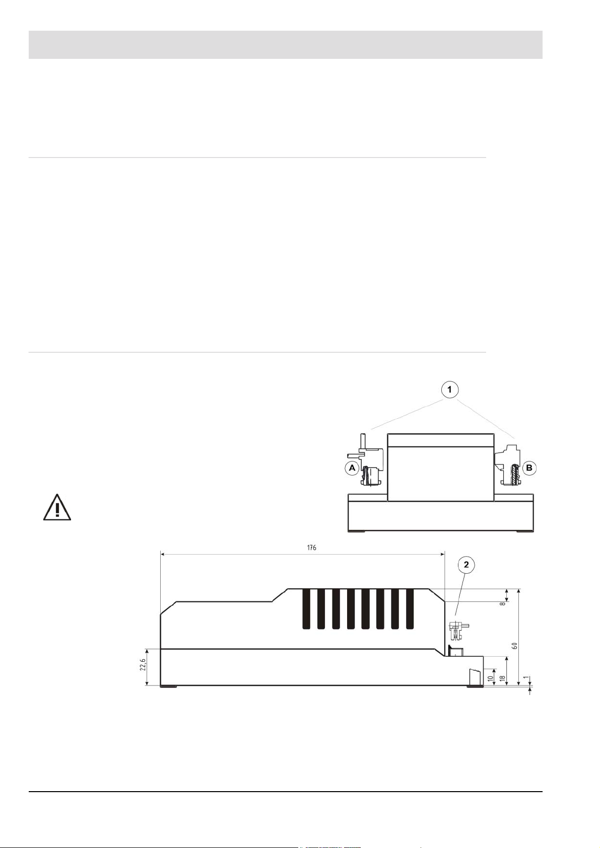
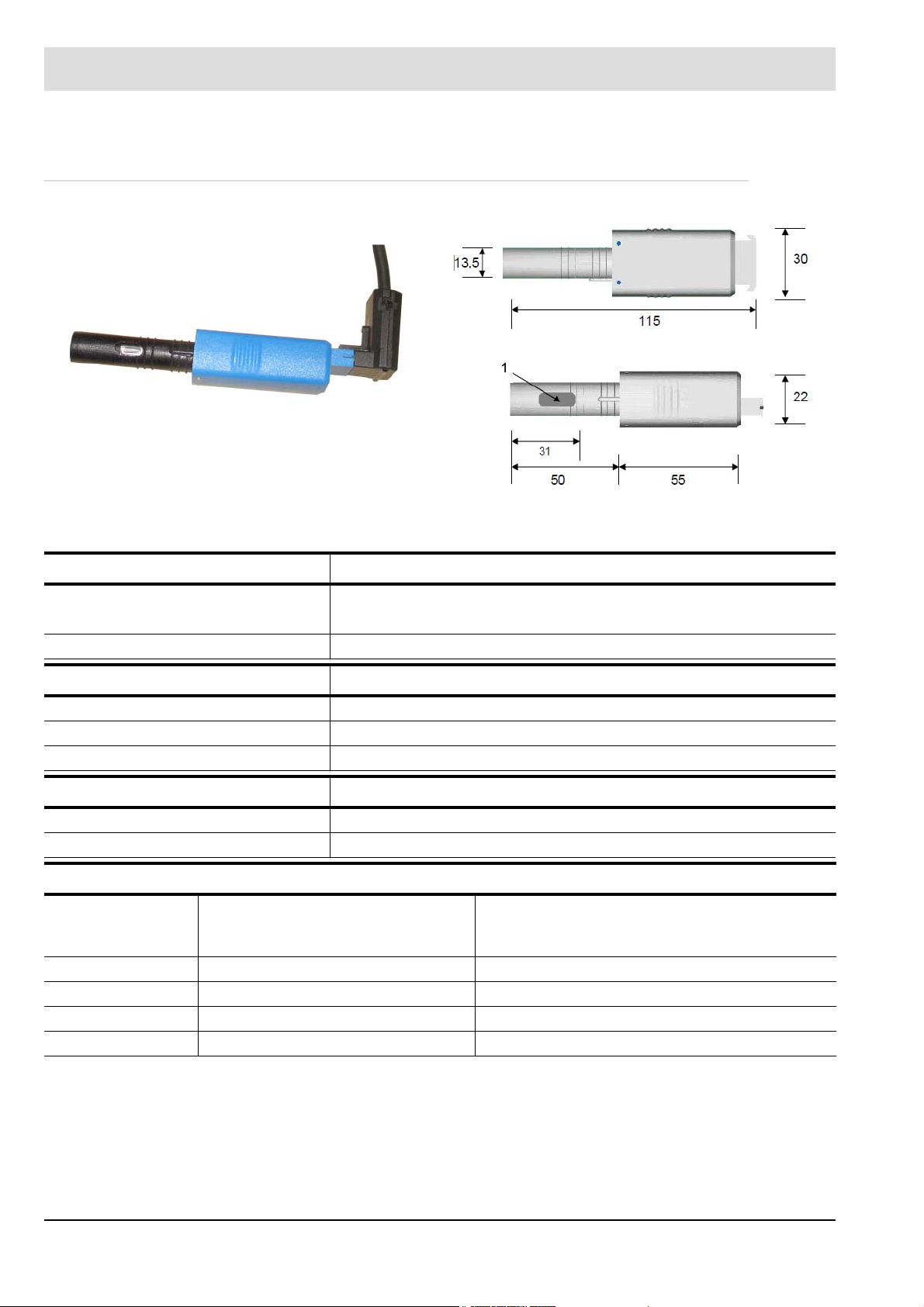
Fig. 3-1 Dimensions BT320 ... 340 (terminal assignment BT330/BT340 only)
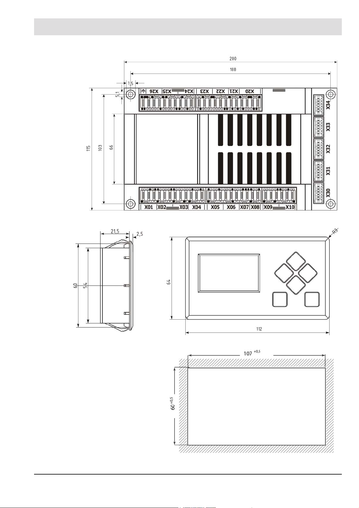
Fig. 3-2 UI300 side view
Fig. 3-3 UI300 front view
Fig. 3-4 UI300 panel cut-out
16
Page 18

3 Product Description
Function
Power supply: 230 V +10/-15 % 47-63 Hz
115 V +10/-15 % 47-63 Hz (on request)
Maximum backup-fuse: 10 A slow-blow
To be used only in a grounded power line network!
Power consumption: max. 30 VA
Switching threshold of ionisation
current:
Digital signal inputs: Max. line length 10 m/33 ft
Digital outputs: 3 fuel valves max. 1 A cos 0,4
Resolution: 999 digit, 10 bit
Number of curve sets: BT320/33x: 1 curve set (oil or gas)
Number of programs: unlimited (EEPROM)
Field bus-coupling (optional): PROFIBUS DP
Housing: Polycarbonate + ABS
Dimensions: 200x115x61 mm/7.87x4.53x2.4 in
Weight: 1,0 kg/2.20 lb
Flammability: UL-94 V0
1 A
Max. line length 20 m/66 ft for the following signals:
Firing rate+ / firing rateBoiler safety interlock chain (SIC)
Burner ON
Reset
Alarm
Fuel selection DFM
VL fan max. 2 A cos 0,4
oil pump max. 2 A cos 0,4
ignition transformer max. 2 A cos 0,2
alarm output max. 1 A cos 0,3
BT34x: 2 curve sets (oil/gas switchable; DFM300 or LCM100 required)
Modbus TCP
PROFINET
LEM100 or LCM100 always required
Display UI300
Display: 128x64 pixel, monochrome
White backlighting (dimmable)
Dimensions: 112x64x24 mm/4.41x2.52x0.94 in
Weight: 140 g/0.31 lb
Housing: Basic housing: Polyamide glass fibre reinforced
LCD-display window: Polycarbonate
Flammability: UL-94 V0
Cable length: 1 m/3.28 ft
Environmental Conditions
Operation: Climatic conditions Class 3K5 according to DIN EN 60721-3
Mechanic conditions Class 3M5 according to DIN EN 60721-3
17
Page 19

3 Product Description
Environmental Conditions
Temperature range -20 ... +60 °C/-4 °F ... +140 °F
(condensation is prohibited)
Transport: Climatic conditions Class 2K3 according to DIN EN 60721-3
Mechanic conditions Class 2M2 according to DIN EN 60721-3
Temperature range -20 ... +70 °C/-4 °F ... +158 °F
(condensation is prohibited)
Storage: Climatic conditions Class 1K3 according to DIN EN 60721-3
Mechanic conditions Class 1M2 according to DIN EN 60721-3
Temperature range -20 ... +70 °C/-4 °F ... +158 °F
(condensation is prohibited)
Electronic safety: Degree of protection (DIN EN 60529): BT300 – IP00 housing
IP20 (terminals covered)
UI300 – IP40 (clamping)
IP54 (glued assembly)
3.3.2 Actuator
3.3.2.1 Actuators 662R550...
18
Page 20
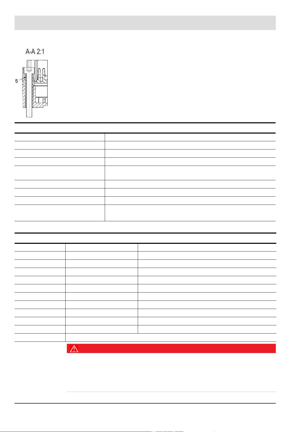
3 Product Description
1 15.4 (+0.3/-1) including axial play
2 Cap cannot be removed by hand
3 Flexible control cable (black), length 1.5 m
4 Plug connector (RAST 2.5) pole number 6
5 Brass tube and M4 x 30 DIN 912 cylinder bolt fixed with O-ring
Function
Power supply 24 VDC ±20 %
Floating time 5 s / 90° at 180 Hz
Direction of rotation 0° to 90° right
Torque 0.8 Nm (both directions)
Holding torque 0.4 Nm (no power)
0.7 Nm
Permissible radial load 30 Nm (centre of output shaft)
Permissible axial load 5 N
Axial play of drive shaft 0.1 ... 0.2 mm
Cable length securely connected 0.6 m
pluggable max. 3 m
Environmental conditions
Operation Climatic condition Class 3K3 according to DIN EN 60721-3
Mechanical condition Class 3M3 according to DIN EN 60721-3
Temperature range -20 ... +60 °C (condensation is prohibited)
Transport Climatic condition Class 2K3 according to DIN EN 60721-3
Mechanical condition Class 2M2 according to DIN EN 60721-3
Temperature range -20 ... +70 °C (condensation is prohibited)
Storage Climatic condition Class 1K3 according to DIN EN 60721-3
Mechanical condition Class 1M2 according to DIN EN 60721-3
Temperature range -20 ... +70 °C (condensation is prohibited)
Bursting strength Peak voltage 4 kV
Repeat frequency 2,5 kHz
Electrical safety Protection class 2 as per DIN EN 60730
DANGER!
Danger by electrical shock!
Shut BT300 down before opening the cover, otherwise it is possible to get in contact with conducting parts. This may cause an electrical shock. Only open BT300 when it is disconnected
it all-pole.
Disconnect BurnerTronic all-pole.
19
Page 21
3 Product Description
NOTICE
Damaging the 0,8 Nm actuator by opening the actuator.
Do not open the actuator at another part as the cover of the electric connection, otherwise the
actuator will be damaged.
The warranty expires and is invalid.
Do not open the actuator but at the cover of the electric connection.
3.3.2.2 Actuators 662R5001... / 662R5003...
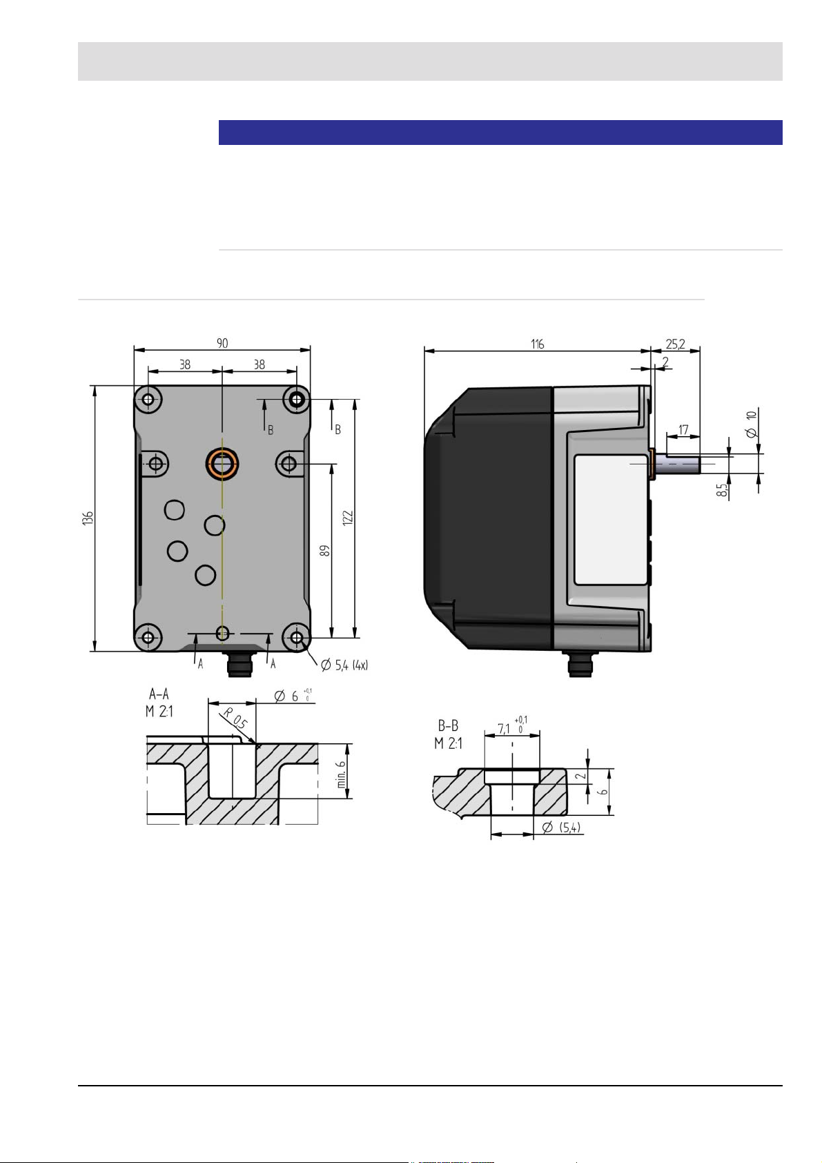
Fig. 3-5 Dimensional drawing of motor type 662R5001-0 and 662R5003-0 without cable but with plug
20
Page 22

3 Product Description
Fig. 3-6 Dimensional drawing of motor type 0R5001-1 and type 662R5003-1 with cable
Fig. 3-7 Dimensional drawing of motor type 660R5009-0 without cable but with plug
21
Page 23

3 Product Description
Function 662R5001... 662R5003... 662R5009...
Power supply: 24VDC ±20 %
Floating time 5 s/90° 5 s/90° 15 s/90°
Direction of rotation 0°
to 90°
Effective
output torque
Holding torque 0.82 Nm (currentless) 2.8 Nm (currentless) 6 Nm (currentless)
Permissible
radial load
Permissible axial load 10 N
Axial play of drive shaft 0.1 ... 0.2 mm 0.1 ... 0.2 mm
Motor RDM 51/6 stepper motor
Angular resolution 0.1°/motor step 0.1°/motor step 0.03°/motor step
Rated resolution
encoder monitoring
Monitoring
accuracy
Repeat accuracy 0,1° 0,1° 0,1°
Life cycle 2,000,000 motions forward and back performed on complete actuator range
Degree of protection IP54 according to DIN EN 60529-1
Weight 1400 g
Cable length securely connected
left - view to the drive shaft
1.2 Nm
(both directions of rotation)
100 N (centre of output shaft)
0,7°
0,5° 0,5° 1.3125°
1.5mpluggable max. 3 m
3 Nm
(both directions of rotation)
securely connected
1.5mpluggable max. 3 m
9 Nm
(both directions of rotation)
(corresponds 44 motor
steps)
pluggable max. 3 m
Environmental conditions 662R5001.../662R5003.../662R5009...
Operation Climatic condition Class 3K5 according to DIN EN 60721-3
Mechanical condition Class 3M5 according to DIN EN 60721-3
Temperature range -20 ... +60 °C (condensation is prohibited)
Transport Climatic condition Class 2K3 according to DIN EN 60721-3
Mechanical condition Class 2M2 according to DIN EN 60721-3
Temperature range -20 ... +70 °C (condensation is prohibited)
Storage Climatic condition Class 1K3 according to DIN EN 60721-3
Mechanical condition Class 1M2 according to DIN EN 60721-3
Temperature range -20 ... +70 °C (condensation is prohibited)
Bursting strength Peak voltage 4 kV
Repeat frequency 2,5 kHz
Electrical safety Protection class 2 as per DIN EN 60730
NOTICE
Damage of the actuator with 1.2, 3.0 and 9.0 Nm due to opening the actuators housing.
Opening the actuator’s housing will damage the actuator. The warranty expires.
22
Page 24
3 Product Description
3.3.3 Flame Sensor/Flame Scanner
Fig. 3-8 KLC 1000
KLC10/KLC1000
Input Data
Power supply: KLC10: 120 VAC -15/+10 % 50-60 Hz
KLC1000: 230/240 VAC -15/+10 % 50-60 Hz
Current consumption: 5,5 mA
Optical Evaluation
Spectral range: 185 - 260 nm
Tolerable flame signal dips: 200 ms
Alignment to the flame: left
Dimensions
Weight: 0,028 kg (1 oz)
Connecting cable length max.: 1 m (39.4")
Environmental Conditions
Operation: Temperature range -20 ...+60 °C (-4 °F ... 140 °F)
Humidity max. 95 % r. h. (condensation is prohibited)
Electrical safety: Protection category IP41
Protection class II
Protecting against contact DIN EN 60730-2-5
Fig. 3-9 Dimensions KLC 1000 (1 = radial scanning opening)
(temperatures >50 °C (122 °F) will reduce life
cycle of the device)
23
Page 25

3 Product Description
Fig. 3-10 Dimensions of angle adapter for KLC 2002 Fig. 3-11 Dimensions KLC 2002
KLC20/KLC2002
Input Data
Power supply: KLC20: 120 VAC -15/+10 % 50-60 Hz
KLC2002: 230/240 VAC -15/+10 % 50-60 Hz
Current consumption: 3 - 4 mA
Optical Evaluation
Spectral range:
Design with optical filter 380 - 830 nm:
Sensitivity max.: 920 nm
Tolerable flame signal dips: 280 ms
Fading of the parasitic frequency: >35 Hz (option)
Dimensions
Weight: 0,029 kg (1.02 oz)
Connecting cable length: 1 m (39.37")
Mounting position: any
Environmental conditions
Operation: Temperature range -20 ...+60 °C (-4 °F ... +140 °F)
Humidity max. 95 % r. F. (condensation is prohibited)
Electrical safety: Protection category IP41
Protection class II
Protection against contact DIN EN 60730-2-5
380 - 1150 nm
(temporarily <1 min. up to +75 °C (+167 °F))
24
Page 26
4 Mounting and Functions
4 Mounting and Functions
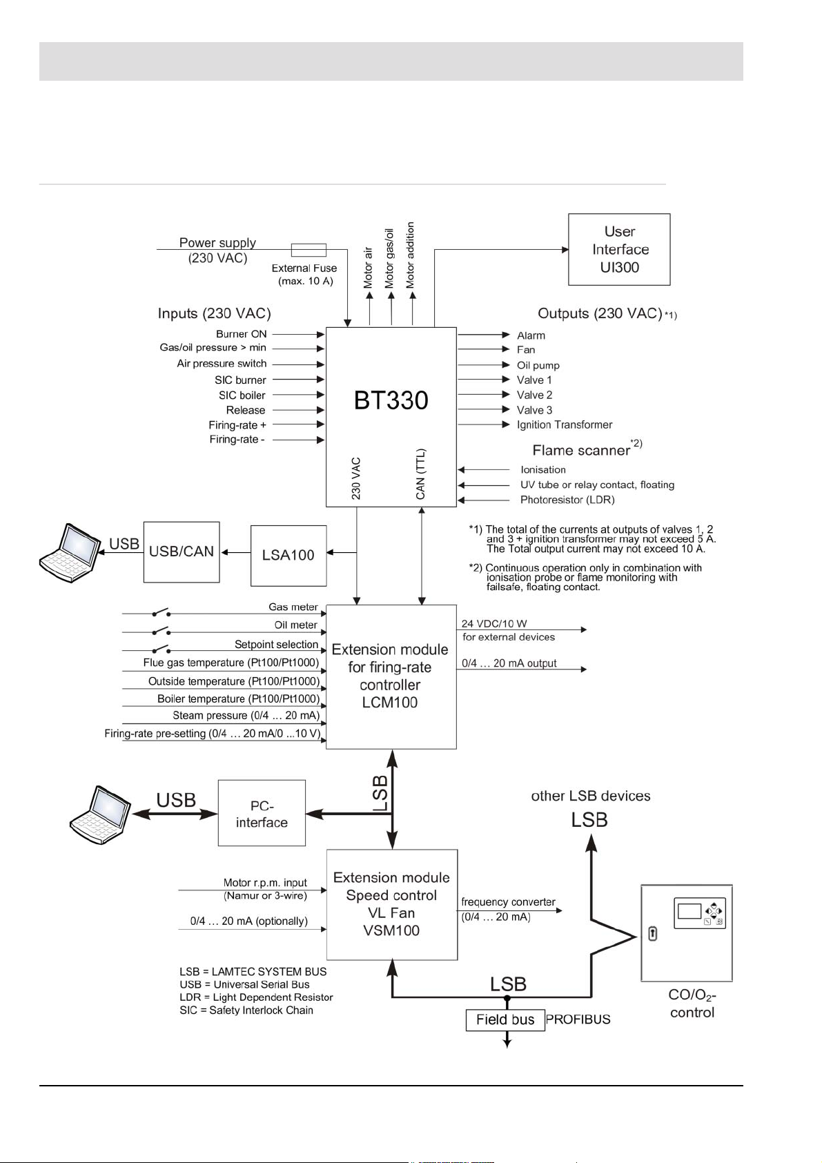
4.1 System Overview
Fig. 4-1 System overview of BurnerTronic BT300
25
Page 27

4 Mounting and Functions
4.2 Connecting Diagrams
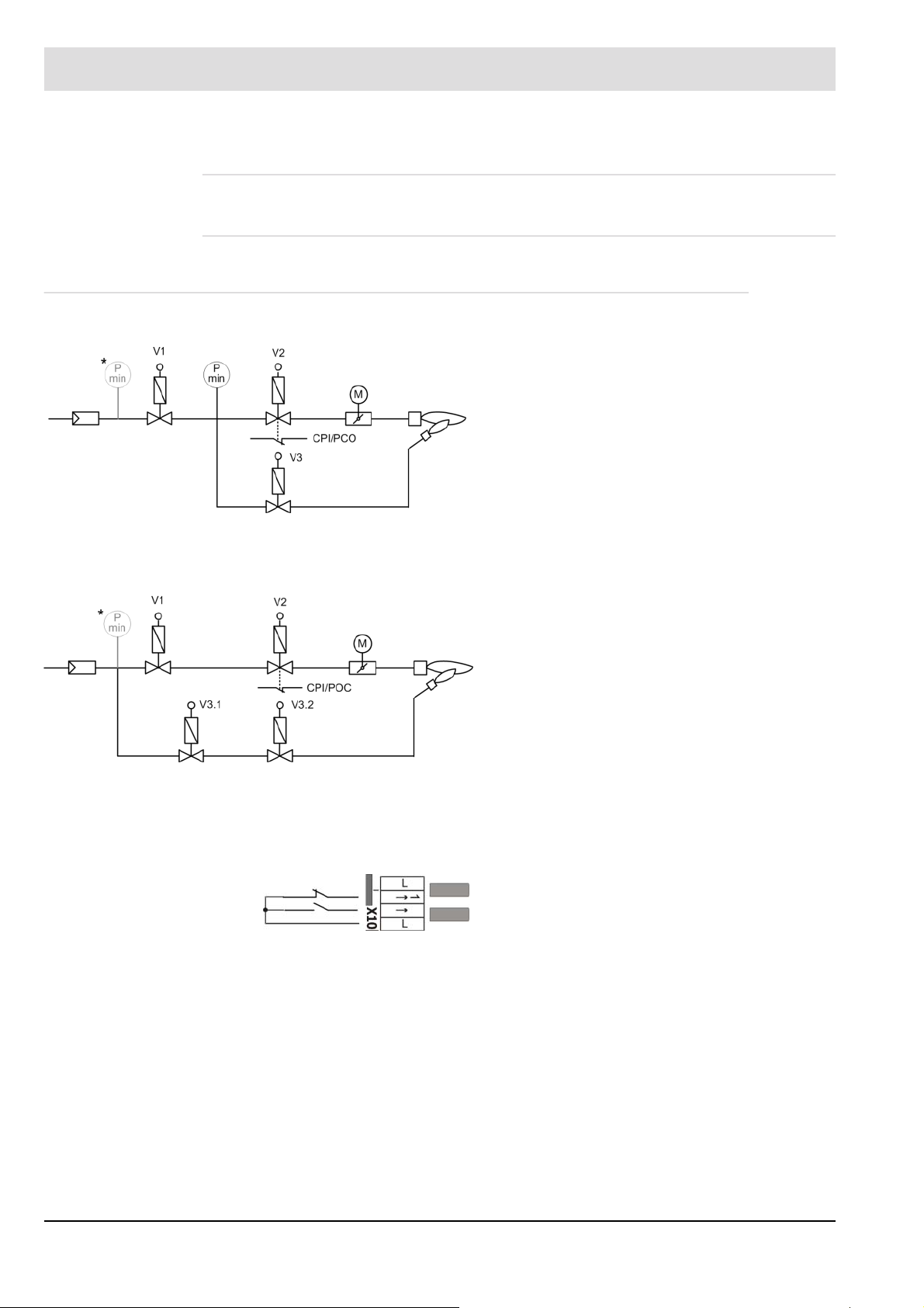
X30 = User Interface UI 300
X31 = LSB Option X01-X6+X08: 10 m
X32 = continuous output 1, e.g. air damper X07+X09: 20 m
X33 = continuous output 2, e.g. gas damper X10: 20 m
X34 = continuous output 3 (optional) X20-X21:
(1)
SIC = safety interlock chain
(2)
230 V AC 47 - 63 Hz external fuse protection required (max 10 A slow-blow)
(3)
230 V AC for power supply to external devices
(4)
Fuel selection for dual fuel burners with BT340 + DFM300 see chapter 7.2 Dual Fuel Module DFM300
(5)
Alternative CPI/POC connection see chapter 4.2.1 Optional Connections for the Fuel Line
Maximum cable length
3 m
X22-X23: unlimited X32-X34: 3 m
X24: 20 m X31: 1 m
X25-X26: 10 m X30: 1 m
WARNING!
Conductors with max. 20 m cable length are allowed to have not more than 3 signal transfers
in one cable, otherwise this would lead to dangerous malfunctions.
Safety interlock chain (SIC) is often known as closed.
NOTICE
When running oil-solely burning applications, the function ’Oil pressure > min’ is aligned with
X05.
26
Page 28
4 Mounting and Functions
When running oil/gas burning applications (BT340 in combination with DFM300), the function
’Gas > min’ is aligned with X05.
►Put in oil/gas applications, the pressure monitoring for ’Oil pressure > min.’ in the oil safety
interlock chain (SIC).
4.2.1 Optional Connections for the Fuel Line
Fig. 4-2 Fuel train - gas modulating
V1 Fuel valve (gas side)
V2 Fuel valve (burner side)
V3 Optional ignition valve
P
min
M Actuator gas damper
*
CPI/
POC
Gas pressure min sensor
Alternative positioning of the pressure monitor P
essary.
Close Position Indicator (UK/AU)
Prove Of Closure (US)
ON switch at gas valve 2 which indicates
that the valve is closed (option)
– if valve leakage check is not nec-
min
Fig. 4-3 Fuel Train - taking pilot gas previous to the main valves (BT300
software version 3.2 or higher)
CPI/POC BT300
Burner ON
V1 Fuel valve (gas side)
V2 Fuel valve (burner side)
V3.1 Ignition valve (gas side)
V3.2 Ignition valve (burner side)
P
min
M Actuator gas damper
*
CPI/
POC
Gas pressure min sensor
Alternative positioning of the pressure monitor P
essary.
Close Position Indicator (UK/AU)
Prove Of Closure (US)
ON switch at gas valve 2 which indicates that
the valve is closed (option)
– if valve leakage check is not nec-
min
27
Page 29
4 Mounting and Functions
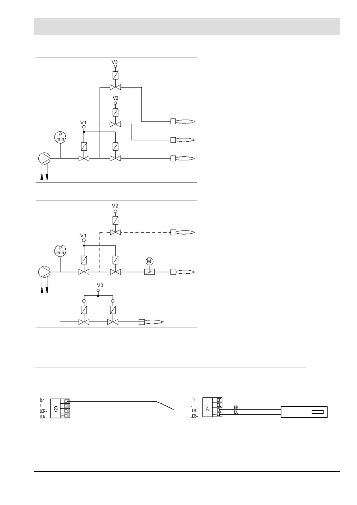
Fig. 4-4 Fuel train - oil 3-stage
P
min
V1 Oil valve 1
V2 Oil valve 2
V3 Oil valve 3
P
min
V1 Oil valve for modulated operation,
V2 Oil valve 2
Oil pressure min sensor
st
stage
nd
stage
rd
stage
Oil pressure min sensor
st
oil valve 1
stage at 2-stage operation
nd
stage at 2-stage operation
V3 Optional ignition valve
M Actuator for control valve oil/modulated opera-
tion
Fig. 4-5 Fuel train - oil modulating - oil 2-stage
Connection of the fuel valves see chapter 7.2 Dual Fuel Module DFM300.
4.2.2 Optional Connections for the Flame Scanner
Electrical connections
Fig. 4-6 Connecting diagram ionisation electrode
28
Fig. 4-7 Connecting diagram photo resistance e.g. Siemens
QRB... or Honeywell MZ770
Page 30

4 Mounting and Functions
Fig. 4-8 Connecting diagram of the sensor Honeywell IRD1020
Colour code BK = black; BN = brown; BU = blue
Fig. 4-10 Connecting diagram F300K via power pack FN20 (also valid for F200K)
Fig. 4-9 Connecting diagram of sensor Honeywell IRD1010,
KLC10, KLC20, KLC1000 or KLC2002
Fig. 4-11 Connecting diagram F152 with FFS07/FFS08
29
Page 31

4 Mounting and Functions
Dimensional Drawings
Fig. 4-12 Dimensional drawing F200K
Fig. 4-14 Dimensional drawing KLC1000/KLC2002 top view
1 Radial opening (with KLC1000 only)
Fig. 4-13 Dimensional drawing F300K
Fig. 4-15 Dimensional drawing KLC1000/KLC2002 side view
30
Page 32

4 Mounting and Functions
4.2.3 LSB Module Integration
1
EBM100 may be
used as an alternative field bus module
instead of PBM100
2
Alternative CO/O2
measurement
3
LEM100 can be used
as an alternative to
LCM100 to connect
LSB to BT100
4
CO/O2 measurement
Fig. 4-16 Connecting diagram LSB module at BT300
31
Page 33

4 Mounting and Functions
NOTICE
Connecting LSB modules to BT300 requires an LCM100 or LEM100 with an external power
supply 24 V SELV.
Connect VSM, DFM and LT3-F as needed on the LSB module.
Only connect H and L of the LCM’s LSB to the LT3-F.
NOTICE
Consider while wiring the LAMTEC SYSTEM BUS (LSB) following notes:
Activate the 120 terminating resistor at first and last device on LSB.
Set dip switch of BT300 module on position 1 (see chapter 7 Options.
When using LT3, pay attention to the device-related manuals.
We recommend for cable length and conductor cross-section with LSB:
Length [m] Cross-section [mm2] Type
0 - 40 m 2x2x0,34 twisted pairs with shielding, impedance 120
40 - 300 m 2x2x0,50 twisted pairs with shielding, impedance 120
300 - 500 m 2x2x0,60 twisted pairs with shielding, impedance 120
Devices on LAMTEC SYSTEM BUS (LSB) must be connected in serial/row (see Fig. 4-17 Se-
rial BUS connection). The first and the last participant on LSB must be terminated with a termination resistor of 120 . All the other BUS participants are not allowed to be connected to
any termination resistor at all. A star wiring is not permitted (see Fig. 4-18 Star BUS connec-
tion).
For activation of the termination resistor, see also technical document LAMTEC SYSTEM
BUS (DLT6095).
Correct: Serial Wiring (in a row)
Fig. 4-17 Serial BUS connection
Incorrect: Star Wiring
Fig. 4-18 Star BUS connection
32
Page 34

4 Mounting and Functions
4.3 Flame Monitoring
4.3.1 Integral Flame Monitoring (Option)
The integral flame monitoring system is designed for standard applications (such as oil and
gas flames in a burner located in a combustion chamber).
The flame monitor has the following tasks in combustion plants:
• Measuring the burner flame, regardless of conditions in the combustion chamber (e.g.
glowing lining)
• Triggering control command internally to shut off fuel feed via burner control unit because
of a flame blow-off.
The following types of flame sensor for intermittent operation (burner switched off at least once
every 24 hours) are valid for use.
Manufacturer Type Settings P 800 Approval
LAMTEC F152 with FFS07 o. FFS08 UV (up to v3.1)
contact (from v3.3)
F200K with FN20 UV (up to v3.1)
contact (from v3.3)
F300K with FN20 UV (up to v3.1)
contact (from v3.3)
Honeywell IRD1010 LDR Intermittent
IRD1020 ION Intermittent
MZ770 LDR Intermittent
SIEMENS QRB1... LDR Intermittent
QRB3... LDR Intermittent
QRA2... UV Intermittent
QRA10... UV Intermittent
QRA4... UV Intermittent
Ionisationselektrode ION Continuous
BST Solutions/
LAMTEC
Continuous = continuous operation
Intermittent = intermittent operation
KLC1000/KLC10 LDR Intermittent
KLC2002/KLC20 LDR Intermittent
Continuous
Continuous
Continuous
NOTICE
For continuous operation, connect following types of flame sensors to BurnerTronic BT330
and BT340:
Flame scanners with ionisation electrode
Flame monitor for continuous operation with potential-free contact e.g. F200K.
The fastening system must be designed in a way that unintentional detachment of the
flame monitor is prevented.
BT320 is despite using these flame sensors approved for intermittent operation only.
33
Page 35

4 Mounting and Functions
WARNING!
Danger from fuel ingress to combustion chamber after loss of flame!
Improper use or configuration of flame sensors not approved for continuous operation can result in hazardous situations and possible cause of explosion leading to loss of life and property. Failure to detect the loss of flame may result in an ingress of fuel into the combustion
chamber and subsequent explosive condition.
Make sure during setting of P300 to the approval of the scanner.
Only set P300 to the value 0 if the flame sensor and the BT300 is approved for continuous
operation.
NOTICE
The flame sensor QRA53 …, 55 …, 73 … and 75 are not authorized together with BT300 for
continuous operation. The test of the UV tube via shutter is not supported by BT300.
4.3.2 Flame Sensors
4.3.2.1 KLC 20/KLC 2002
Brief Description
The wide band flame detector KLC 20/KLC 2002 is a compact flame detector, which is special
designed for blue burning combustion systems. The patented flame signal evaluation is based
on the flicker frequencies of the flame. A RISC-Processor enables evaluation and conversion
of the flame signal into digital information to provide an output signal for burner control boxes.
All flames will be detected by an automatic sensitivity control. Adjustments during commissioning and maintenance are not necessary!
Per international standards, the KLC 20/KLC 2002 will only detect signals caused by the flame
flicker. Signals from continuous radiation and any kinds of constant frequency will be ignored.
Signals caused by disturbing light sources, such as fluorescent tubes or background radiation
from hot refractory will be cut off, so that unwanted influences are not possible.
By using LED-Display as an optical interface, the flame detector is able to read different relevant operating parameters (e.g. monitoring of flame signals, serial number).
Safety Instructions
The KLC 20/KLC 2002 is a safety device. Do not open, modify, or misuse it! Replace the flame
detector in case of any damage, if dropped, exposure to shock, moisture, excessive temperature, or conditions that can destroy the flame detector, even though damage is not obvious.
Repair is strictly prohibited!
Before working on the flame detector, switch off the power supply. Before first commissioning
or replacement of the device, check external wiring!
Mounting Instructions
The KLC 20/KLC 2002 should be mounted close to the flame with straight alignment using the
Mounting Flange KLC or another suitable holder with Ø0.551 inch (14 mm) opening. Mount
the detector with a holder. The best flame signal will be achieved from strong flickering parts
of the flame radiation. The angle of view, especially with sight tubes, must be of appropriate
dimensions to avoid any reduction of flame radiation. Protect the sensor from other light sources.
34
Page 36

4 Mounting and Functions
NOTICE
To avoid any disturbance, do not align the detector direct to the ignition spark. Breakdowns
during pre-purge procedure may occur.
The maximum length of the connection must be in accordance with the technical data. Install
the detector connection cable with most possible distance to the ignition cable or the mains
cable. Avoid to lay the connecting cable in parallel to these cables.
CAUTION!
Due to safety and technical regulations, a control shut down must be done at least once
every 24 hours.
Operating Indicator LED
Via the built-in LED the flame detector KLC 20/KLC 2002 is indicating the following operating
conditions:
LED is OFF KLC is not active.
LED is blinking KLC is active, safety test finished, no flame detected
LED is ON KLC is active, safety test finished, flame detected
Mounting Flange KLC
The Mounting Flange KLC provides attachment and adjustment of the flame detector.
The Mounting Flange KLC can be simply
sealed to the burner housing using an o-ring.
Height = 0.3 in (7 mm).
Viewing Angel Adapter KLC
for radial adjustment
Radial adjustment of the KLC2002 to the
flame axis is possible with the optional viewing angle adapter, which can replace the
Mounting Flange KLC. An optionally available
angle adapter provides the radial adjustment
to the flame axis of KLC2002 by an optimally
shaped reflector surface. A special flame
scanner type is not necessary. During handling, avoid touching the reflector surface
and, if necessary, clean with a dry, soft and
lint-free cloth.
Maintenance
To maintain the detector, just keep the sight glass clean by using a dry cloth. Do not use any
kind of cleaning sprays or liquids. The flame scanner may only be touched at the lateral, corrugated regions when inserting or withdrawing it from the mounting flange.
Due to internal checks of the KLC 20/KLC 2002 no more tests are necessary. The flame scanner’s make circuit/break circuit can be checked easily by holding the flame scanner to an AC
operating light source (no torch or similar).
35
Page 37

4 Mounting and Functions
KLC 20/KLC 2002 switches the flame relay ON – the red LED is permanently ON. After 9 sec.
the switching output is disconnected – the red LED flashes.
NOTICE
Due to the safety function of the disturbance frequency cut-off, a flame simulation is not possible by means of a simple art source of light. If a flame simulation, such as during the final
inspection of the burner without a real flame is needed, a source of light with a modulating frequency between 60 and 150 cycles per second.
Disposal Information
The flame detector is equipped with electrical and electronic components and must be disposed separate from household waste. Follow the local and actual regulations for waste disposal.
4.3.2.2 KLC 10/KLC 1000
Brief Description
The KLC 10/KLC 1000 is a compact UV flame detector, which has been developed for single
flame combustion which produces little light or radiation in the visible spectrum and has very
low flame modulation/flicker frequency. The design of the UV sensor ensures that the flame
detector does not react to background radiation from hot refractory or from any other infra-red
light source.
Flame intensity can be easily recognised by an optical LED display.
The flame detector KLC 10/KLC 1000 has been developed to meet the requirements of Euro-
pean Standards EN230 and EN298 for burner management control units which make a ‘noflame’ check after normal burner shut down when the flame amplifier is permanently energised.
Safety Instruction
The KLC 10/KLC 1000 is a safety component, and repair or adjustment must never be attempted. Replacement of the flame detector is recommended in all cases of damage, due to
impact shock, excessive moisture, or other problems rendering it inoperable. Repair work
must never be attempted and is strictly forbidden by the relevant European Standards.
WARNING!
Prior to commissioning the unit; carefully check that the wiring connections have been made
correctly. Also, before removing or checking the flame detector make sure the power supply
is switched off.
Mounting Instructions
The KLC 10/KLC 1000 should be mounted as close as practical to the flame and on the same
axis. The flame detector is compact and should be mounted with the KLC mounting flange or
other suitable holder having a 14mm Ø opening. Fix the detector in the holder taking care to
protect the sensor from other light sources.
To avoid any problems at start-up; please avoid alignment of the KLC detector with the ignition
spark electrode as the flame detector may react with the ignition spark and cause burner shutdown during the air pre-purge/ignition start-up sequence. The maximum length of the connection cable must be in accordance with the technical data. Please ensure that the flame detector connection cable is kept well apart and is completely separated from high-energy igniterand power cables to avoid electrical interference problems.
36
Page 38

4 Mounting and Functions
CAUTION!
For safety reasons and within the technical regulations, a controlled burner shut-down
of the burner must occur and be guaranteed to happen at least once in every 24 hours
of operation.
Operating Indicator LED
The flame detector KLC 10/KLC 1000 indicates the following operating conditions and flame
signal strengths via the built-in LED.
LED is OFF KLC is not switched on – no power supply or ‘no flame’ is detected
LED is FLASH-
ING
LED is ON KLC has detected the strongest level of flame signal.
KLC has detected a flame; the quality of the flame signal is indicated by
the intensity of the flashing of the LED – fast flashing indicates a healthy
flame signal and vice versa - slow flashing indicates a weak flame signal.
Mounting Flange KLC
The mounting flange allows the detector to be
held and adjusted in a suitable position to
view the flame. An O-ring seal is available
which will give the mounting flange an air tight
seal to the burner housing if required.
Height = 7 mm.
Maintenance
The installation and commissioning must be done by qualified personnel only. Before energizing the KLC flame detector, check the cable and wiring connections if they are in accordance
to the diagram of the burner manufacturer. For good maintenance which will ensure trouble
free operation of the KLC flame detector; keep the sight glass clean by wiping with a soft dry
clean cloth. During commissioning and after any cleaning maintenance, the flame detector
should be checked, as the UV tube is subject to a natural ageing process and towards the end
of its life span (ca. >10.000 h at an ambient temperature of <50 °C) it is prone to malfunction.
To check that the flame detector is sound, we recommend the following procedures be followed:-:
• When starting the burner sequencer, the flame scanner must be shaded - after ending of
the safety time the burner sequencer must run to fault condition!
• When starting the burner sequencer, the flame scanner must be lighted up by an external
UV radiation e.g. pocket lighter or gas flame (ambient light/room illumination is not sufficient) – the burner sequencer must run to fault condition during pre-purge period!
• In BURNER OPERATION the flame scanner must be shaded – depending on the burner
sequencer’s type, the burner sequencer must run to fault condition either after restarting
at the end of the safety time or directly after shading the flame scanner.
Disposal Instructions
The flame detector is equipped with electrical and electronic components and must be disposed separately from household waste. Follow the local authority regulations for electrical
component waste disposal.
37
Page 39

4 Mounting and Functions
4.4 Process Sequence Charts
Key to process sequence charts
Any condition
t1 Waiting for safety interlock chain gas, scan of air pressure monitor min. any
t2 Time for pressure build-up in the gas test line (available with activated leakage test) 2,4 s
t3 Actuator running time 30 s - 60 s
t4 Delay of the recirculation damper 0 - t5
t5 Pre-purge period adjustable
t6 Pre-ignition time adjustable
st
t7 1
t8 Stabilisation period adjustable
t9’ 2
t10 Operating phase any
t11 Control mode any
t12 Time for pressure relief in the gas test line 3 s
t13 Post-purge period adjustable
t14 Control elements at base load/firing rate
t15 After burning time adjustable
t16 Checking flame extinction 5 s
t17 Leakage test, gas valve 2 30 s
** Recirculation is released as soon as the flue gas threshold P322 is reached and the
CPI Close Position Indicator (UK/AU)
POC Prove Of Closure (US)
safety period 3 s gas/5 s oil
nd
safety period 3 s gas/5 s oil
delay time in P331 has expired after reaching operation position (base firing-rate/
control).
Limit switch on gas valve 2 which indicates that gas valve 2 is closed.
Limit switch on gas valve 2 which indicates that gas valve 2 is closed.
38
Page 40

4 Mounting and Functions
Fig. 4-19 Oil with pilot burner BT300
39
Page 41

4 Mounting and Functions
Fig. 4-20 Oil without pilot burner BT300
40
Page 42

4 Mounting and Functions
Fig. 4-21 Gas with pilot burner and leakage test BT300
41
Page 43

4 Mounting and Functions
Fig. 4-22 Gas without pilot burner and leakage test BT300
42
Page 44

4 Mounting and Functions
Fig. 4-23 Leakage test BT300
4.5 Leakage Test for Main Gas Valves
4.5.1 Calculation Example
With BT300 the gas pressure monitor is also applicable to the monitoring of minimal gas pressure. Therefore the minimal gas pressure of the burner must be set.
The valve leakage test time t3 (P 311) would be set by BT300. The time t2 for BT300 is fixed
to 2s. The time t3 (P 311) must be set in a way that the maximum allowable leakage rate Q
can be securely detected. The maximum leakage rate stated in EN1643 and ISO23551-4 is
0.1% of the nominal volumetric flow of the gases or a minimum of 50l/h.
43
Leck
Page 45

4 Mounting and Functions
Example 1
Burner capacity =1000 KW
Fuel = natural gas H, calorific value = 10 kW/m
Nominal volumetric flow of the gases = 100 m3/h
Leakage rate max. = 0,1 m3/h or 100l/h
Example 2
Burner capacity =1000 KW
Fuel = propane, calorific value = 25,9 kW/m
Nominal volumetric flow of propane = 38,6 m3/h
Leakage rate max. = 50 l/h (not 38,6 l/h)
Calculation
3
3
Fig. 4-24 Principle scheme
The test volume V
must be calculated with tube diameter and valve volume. The value vol-
test
umes are provided by the valve manufacturer. If valve 1 and valve 2 are be used as a double
valve, the test volume would be provided by the valve manufacturer.
The leakage test V
is calculated according to the Boyle-Mariotte principle.
Leak
p1 V1 = p2 V2
p = absolute pressure
V = gas volume
This is valid for the test of valve 1 V1:
Should t3 be negative, at least 1s must be set.
If the calculation of t3 for valve 2 is higher than t3 for valve 1, the value for the calculation of
valve 2 must be adjusted.
44
Page 46

4 Mounting and Functions
Q
leak
p
sw
Leakage rate in l/h
Absolute pressure on the switching point of pressure monitor (adjusted over-
pressure + atmosphere pressure)
p
p
p
V
sw e
out e
Atm
test
Adjusted overpressure on switching point of pressure monitor
Output pressure on gas valve V2 during purge
Atmospheric pressure (average of 101,3 kPa at sea level)
Test volume between the valves
t2 Settling time is always 2 s
t3 Adjusted leakage check time
NOTICE
p
must always be higher than p
Schalt
out.
Otherwise V1 would be recognised as leaking even if it is not.
This is valid for the test of valve 2 V2:
If t3 is negative, at least 1 s must be set.
If the calculated t3 value of valve 1 is higher than t3 for valve 2, the calculated value of valve
1 must be adjusted.
Q
leak
p
sw
Leakage rate in l/h
Absolute pressure on switching point of pressure monitor (adjusted overpres-
sure + atmosphere pressure)
p
p
p
p
V
sw e
in
in e
Atm
test
Adjusted overpressure on the switching point of pressure monitor
Absolute input pressure on gas valve V1
Overpressure at gas valve V1 input
Atmosphere pressure (average of 101,3 kPa at sea level)
Test volume between the valves
t2 Settling time is always 2 s
t3 Adjusted leakage check time
45
Page 47

4 Mounting and Functions
4.5.2 Leakage Test Process Flow
The valve leakage test checks if the main gas valves are sealed. For this purpose the gas
pressure of the supply is analysed.
As valve leakage test section (space between the two main valves) burns empty whenever
the burner is switched off, this part is usually pressureless at start-up (gas pressure > min =
0). This is checked by BT300. At this point, main gas 1 opens briefly and gas flows into test
section (gas pressure > min switches from 0 to 1). While main gas 1 valve is open gas pressure must apply.Otherwise BT300. detects gas deficiency. Gas pressure must remain at least
constant during valve leakage test period (2 s + P 311). The valve leakage test is considered
complete then.
If leakage test section is not empty at start-up (e.g. resulting from a previous fault shut down),
main gas valve 2 opens first. The leakage test line is then purged (depending on the plant,
either in the combustion chamber or through the roof – for wiring proposition, see chapter
4.5.4 Valve Leakage Test Venting Over the Roof). During leakage test period section is
checked whether it remains pressureless or not. Apart from that the process is the same as
described above.
The leakage test takes place prior to ignition.
The pressure monitor for the leakage test line must be connected to the ’Gas pressure > min’
input on plug X05. It also monitors the minimum pressure during operation. If a different minimum pressure should be monitored during operation, the pressure monitor must be inserted
into the safety interlock chain gas or into the controller loop (burner ON).
46
Page 48

4 Mounting and Functions
Fig. 4-25 Leakage test process diagram
47
Page 49

4 Mounting and Functions
4.5.3 Reaction on Gas Deficiency
If main gas 1 valve is open and the pressure drops below the minimum pressure, gas deficiency is detected. This causes a safety shut down and fault indication H611. Further reactions are
depending on the settings in P301 (automatic restart).
If P301 = 1 (no automatic restart) BT300 remains permanently in a fault position and must be
unlocked if gas pressure returns.
If P301 = 0 (automatic restart according to TRD) or P301 = 2 (automatic restart according to
EN676), BT300 waits until the delay in P328 has elapsed and tries to start again then.
If gas deficiency is detected once more the delay will be doubled with every further attempt to
restart until a delay one hour is reached.
The remaining delay is displayed in the User Interface UI300.
Fig. 4-26 Indication of fault H611 gas deficiency with restart
4.5.4 Valve Leakage Test Venting Over the Roof
NOTICE
Consider diameter of gas line in the roof purge. For purge, plug X02 is activated for 3 s.
Make sure that this period is sufficient even for smallest purge line diameter!
48
Page 50

4 Mounting and Functions
Fig. 4-27 Wiring proposition for purge of gas line via roof in combination with BurnerTronic
4.6 Staged Operation
Function
BT300 has not only the ability of shifting the burner firing rate in oil operation infinitely but 2stage and 3-stage. Therefore oil valve 2 and oil valve 3 is switched ON and OFF depending
on the position of air channel 1.
NOTICE
O2 trim is not possible in 2-stage operation because O2 trim needs a minimum of 3 curve
points.
49
Page 51

4 Mounting and Functions
Fig. 4-28 Switching threshold of stage operation
V2
V2
V3
V3
on
off
on
off
Switch-on point valve 2 P 528 ... P 530 Parameters 528 ... 530
Switch-off point valve 2 S1 ... S3 Threshold 1 ... 3
Switch-on point valve 3 IFR Internal firing rate
Switch-off point valve 3 ZP Ignition point
Firing Rate Controller
If firing rate controller is realised by TPS inputs at BT300 or DFM300 the signals are valued
as follows:
Firing Rate + Firing Rate – Stage
OFF OFF 1
OFF ON 2 not recommended!
ON OFF 2
ON ON 3
The firing rate thresholds are defined in P531 ... P534 if firing rate controller is realised by the
following options:
• Firing rate controller in LCM100
• TPS input at LCM100
• Bus
50
Page 52

4 Mounting and Functions
NOTICE
When using TPS input via X9.x P 531, P 532, P 533 and P 534 are not necessary.
Example for a 2 stage oil burner with firing rate controller by LCM100:
Situation:
• The burner has only one air flap at channel 1.
• The burner is ignited directly at an air flap position of 288 Digit.
This position is stage 1.
• The 2nd stage has an air flap position of 793 Digit.
• At air flap position of 520 Digit the valve for the 2nd stage is switched ON (P 527).
• At air flap position of 500 Digit the valve for the 2nd stage is switched OFF again (P 528),
when switching from the 2nd stage to the 1st stage.
• As soon as the firing rate request of LCM100 exceeds 430 Digit (P 531) the change over
Sequence:
• The burner starts and remains at the base firing rate of 200 Digit as long as LCM100 does
• If the firing rate request of the LCM100 is 430 Digit, the air flap actuator runs open.
• As soon as a position of 520 Digit is reached, the 2
• As soon as the firing rate request of LCM100 drops below 350 Digit the air flap closes
• If the air flap drops below a position of 500 Digit the 2
st
from 1
stage to 2nd stage starts.
If the firing rate request of LCM100 drops below 350 Digit (P 532) the change over from
nd
2
stage to 1st stage starts.
not request a higher firing rate than 430 Digit.
The air flap remains on a position of 288 Digit.
flap runs to the operation position of 793 Digit.
The internal firing rate is 300 Digit.
again.
The air flap runs to a position of 288 Digit. The internal firing rate is 200 Digit.
nd
oil valve is switched ON and the air
nd
oil valve is switched OFF.
4.7 Flue Gas Recirculation
To recirculate exhaust gases from the flue, either the combustion air fan or a recirculation fan
can be used. If a recirculation fan is used then it is controlled in parallel with the combustion
air fan.
The operation of a recirculation fan is controlled by either a differential pressure switch mounted across the fan or an absolute pressure switch mounted on the fan's positive pressure side.
Fig. 4-29 Interconnection of the pressure monitors
1 = Recirculation
pressure monitor
2 = Air pressure monitor
51
Page 53

4 Mounting and Functions
Negative pressure created by the combustion air fan can be used as an alternative to a recirculation fan to aspirate flue gases. For this method of flue gas recirculation it is sufficient to
monitor the combustion air fan. It is not possible to use a VSD controlled recirculation fan with
the BT300 system.
Program Sequence of BT300 with Flue Gas Recirculation
The action of the fuel and air actuators is not affected by the flue gas recirculation.
The recirculation damper stays closed at the beginning of the pre-purge period.
After the adjusted delay (P 414) the pre-purge period is stopped temporarily and the recirculation channel runs to OPEN position.
After the end of the pre-purge period the air damper runs to the ignition position. The fuel actuators are already in ignition position and the recirculation channel runs to CLOSE position.
After reaching this position, the burner ignites.
Only the fuel and air actuators run to the curve after the BT300 has changed to CONTROL
mode.
The recirculation channel remains at its position until the release conditions were met.
Subsequently the recirculation channel runs to the curve.
The recirculation channel is only released once the time period set in P331 has expired and
the release temperature P332 has been met.
If the temperature drops below the threshold set in P332 during operation the recirculation remains active.
The recirculation channel runs to the CLOSE position at a flue gas temperature of 0 °C (32 °F)
– interruption of the temperature sensor.
During decommissioning the program sequence remains the same for fuel and air actuators.
The recirculation channel will be closed together with the fuel actuator.
NOTICE
LCM100 is always mandatory.
Terminals 29 and 30 must always be short-circuited at the LCM100 regardless of whether a
temperature sensor is connected or not.
4.8 Actuator
4.8.1 Operation after Power ON/Long RESET
The actuators have internal position feedback using an incremental encoder. For automatic
alignment of positioning the actuators run short of the 12 o'clock position by 2.8°. The actuators carry out a transposition test, if activated by P 461. After passing this test the actuators
move to position for the closed damper.
4.8.2 Direction of Rotation/Position Damper Closed
For actuator 662R550... (0.8 Nm) direction of rotation of factory setting is clockwise in quadrant from 12 o'clock to 3 o'clock position (P 458 - P 460/channel 1 - channel 3). Adjust ’closed
damper’ position between 12 o’clock and 3 o’clock position as follows:
• 12 o’clock position P 458 - P 460 = 0
• 3 o’clock position P 458 - P 460 = 1
For actuator 662R5001...(1,2 Nm), 662R5003...(3 Nm) and 662R5009... (9 Nm) direction of
rotation of factory setting is counter-clockwise in quadrant from the 12 o'clock to 9 o'clock position (P 458 - P 460/channel 1 - channel 3). Adjust ’closed damper’ position between 12
o’clock and 9 o’clock position as follows:
52
Page 54

4 Mounting and Functions
• 12 o’clock position P 458 - P 460 = 0
• 9 o’clock position P 458 - P 460 = 1
4.8.3 Detection of Actuators with Transposed Connections
While replacing BT300 make sure actuators are re-connected to the correct channel. Label
the plugs/cables to prevent faults or use the ’transposition test’ in BT300 (parameter 461 = 1).
To detect transposition of actuators you must implement certain features into burner design.
• The actuator on channel 1 requires a mechanical stop at an angle of 94° (+- 2°).
• The actuator on channel 2 requires a mechanical stop at an angle of 104° (+- 2°).
• The actuator on channel 3 does not need a mechanical stop.
After a long RESET (e.g. after BT300 is switched on), all actuators automatically align position
detection.
Next, channel 1 will not be moved, channel 2 moves on 99° further from 12 o'clock position
and channel 3 moves 108.5° in a clockwise direction.
If actuators are connected to correct channel, none of the actuators will be blocked.
If two actuators are transposed, one of the actuators is blocked and therefore does not reach
its target position. This leads to an error message, and a burner start-up is prevented.
4.8.4 Adjusting of Actuators
The actuators 662R550... (0,8 Nm), 662R5001... (1,2 Nm), 662R5003... (3 Nm) and
662R5009... (9 Nm) differ in their control system. Therefore define in parameters 455 - 457
the actuator connected:
Value Actuator
1 662R550..., 662R5001..., 662R5003...
2 662R5009...
CAUTION!
An incorrect value causes a failure alignment of positioning! (see chapter 4.8.1 Operation after
Power ON/Long RESET
53
Page 55

4 Mounting and Functions
Fig. 4-30 Actuators 662R5001..., 662R5003..., 662R5009
1 External, mechanical stop on channel 2
for detection of transposition
2 External, mechanical stop on channel 1
for detection of transposition
3 Operational range
4 Reference mark
Fig. 4-31 Actuators 662R550...
1 Reference mark
2 Internal mechanical stop
3 Max. angle of rotation for detection of
transposition
4 External, mechanical stop on channel 1
for detection of transposition
5 External, mechanical stop on channel 2
for detection of transposition
6 Internal mechanical stop
54
Page 56

5 Operating Control and Displays
5 Operating Control and Displays
5.1 User Interface UI300
5.1.1 UI300 User Interface
1 Display
2 BACK key
3 Cursor keys
4 ENTER key
Fig. 5-1 User Interface
Display
The display shows in pictogram:
• the menu structure
• operating status
• parameters
• error messages
Back key
Back to previous window.
Cursor keys
To navigate in the menu using cursor keys
Use ’left’ and ’right’ keys to move step by step in a selected row. At the end of the
selected row the cursor jumps down to the next row, if possible.
In a multiline menu use ’up’ and ’down’ keys to switch to other rows.
To display parameters, switch between various fields.
ENTER keys
5.1.2 Menu Functions
The menu is divided into five paths:
Press ENTER to call up a menu on the start screen. Select a sub-menu in the menu
window. Transfer setting values by pressing ENTER key in a parameter window.
Use a flushing, red ENTER key to release a fault interlocker.
If the ENTER key is permanently lit red, a fault with an automatic restart is displayed.
55
Page 57

5 Operating Control and Displays
INFO
MANUAL
SETTINGS
DATA PROCESSING (release level 1 is mandatory)
INFO
Select INFO path for information about the following:
• Burner
• Faults/Fault history
• Software version
• Display of check sums
• Serial number
• Actuator positions (current damper position for each channel)
• Digital inputs/outputs
MANUAL
Select MANUAL to:
• Start and stop burner by hand
• Adjust internal burner firing rate
SETTINGS
Select the SETTINGS path for getting information/make changes to:
• Password
• Burner settings (display and settings)
• Actuator elements settings (display)
• Air/fuel control system
• Deletion of curve sets
• Display settings
DATA PROCESSING
Use DATA PROCESSING to:
• Read out datasets from the BT300
• To transfer datasets to the BT300
56
Page 58

5 Operating Control and Displays
5.1.3 Main Menu
Fig. 5-2 Main menu
* Excess level 1 is mandatory
For a complete description of the display symbols, see chapter 10.1 Display Symbols
5.1.4 Information Menu Path
1 INFORMATION menu path [selected]
2 Display of fuel type
3 Bar graph of internal firing rate in %
(0 - 100)
4 MANUAL menu path
5 SETTINGS menu path
6 Release level
7 DATA HANDLING menu path
8 Window number
*
Burner information Fault history Software version Check sum
Serial number Configuration of actual value of
actuating outputs (display only)
Digital inputs/
outputs
57
Page 59

5 Operating Control and Displays
5.1.4.1 Burner Details
Displaying Operating Hours and Burner Starts
Display of operating hours Number of operating hours in total (device
connected with mains)
Number of operating hours in oil operation
Number of operating hours in gas operation
Display of burner starts Number of burner starts in oil operation
Number of burner starts in gas operation
58
Page 60

5 Operating Control and Displays
5.1.4.2 Recalling Fault History
Displaying Burner Faults
01 02Fault code (Last 10 faults are stored,
no. 01 is the latest fault)
D1 Diagnostic code 1 Duration of the fault
D2 Diagnostic code 2
NOTICE
Information concerning fault and diagnostic codes can be found in the list of fault codes.
For fault analysis a fault code and diagnostic code D1 or D2 is required.
59
No. of operating hours when
fault has occurred
Page 61

5 Operating Control and Displays
Fault unlock
How to unlock BT300
A fault is pending and the ENTER key is flashing.
1. Press ENTER key.
BT300 is not locked anymore.
Changing from fault unlock to main menu:
A fault is pending and the ENTER key is flashing
1. Press BACK key.
ENTER key isn’t flashing any more.
The display returns to main menu.
An error number is flashing in the display on top, left hand.
UI300 can be used as usual.
Back to fault unlock
An error number is flashing in the display on top, left hand.
1. Use BACK key to switch back to main menu.
2. Press arrow-key left.
ENTER key is flashing again.
BT300 can be unlocked.
NOTICE
A permanent red light on the ENER key indicates gas shortage. A countdown is running to the
next start. This countdown can be interrupted by the ENTER key.
5.1.4.3 Software Version
Display software version
UI = Software version UI300
BT = Software version BT300
5.1.4.4 Display of Check Sums
Displaying Check Sums
0 ... 4 = Check sum, access levels 0 ... 4
The checksums are generated from the device parameters. The BT300 calculates one
checksum for the parameters of each access level (0, 1, 2 or 4). The UI300 indicates the
checksums in hexadecimal code.
60
Page 62

5 Operating Control and Displays
The checksum shows whether the value of one or more parameters have been changed.
5.1.4.5 Serial Number
UI = Serial numberUI300
BT = Serial number BT300
5.1.4.6 Positions of Actuators
Indication of the channel’s actual (left to right):
Channel 1 (oil)
Channel 2 (air)
Channel 3 (oil)
Optional channel (OFF; control of the frequency inverter)
NOTICE
The assignment of channels is depending on configuration settings!
61
Page 63

5 Operating Control and Displays
5.1.4.7 Check Digital Inputs/Outputs
Check Digital Inputs and Outputs
Fuel selection oil
Fuel selection gas
Burner ON
Oil pressure min. is present
Gas pressure min. is present
SIC* oil is closed
SIC* boiler is closed
Flame signal is present
Fault release
* SIC = safety interlock chain
NOTICE
The signals ’Fuel selection oil’ and ’Fuel selection gas’ are logical and not physical signals.
Background: Some signals have more sources than one (terminals, LSB, field buses, param-
eters).
Fan ON/OFF
Fault
Ignition transformer ON/
OFF
Ignition valve ON/OFF
Oil pump OFF
62
Page 64

5 Operating Control and Displays
5.1.5 Manual Menu Path
MANUAL
Select MANUAL path to carry out actions as follows:
1 Switching burner ON and OFF
2 Presetting of burner firing rate
Start burner manually
Adjust burner firing rate
NOTICE
At least release level1 is mandatory to start the burner.
The ’Burner ON’ control loop does not need to be switched on to start the burner from this
menu. The user interface assumes control in this menu.
If there is no ’Burner ON’ signal from other sources (terminal X10.2) software switches off the
burner when you exit the menu.
CAUTION!
If you carry out a manual start-up via display BT300 no longer responds to ’Burner ON’ signal
input at connector X10.2. Therefore that limiters, monitors and other similar safety functions
must not be operated with this input!
NOTICE
Leaving of window will terminate manual burner operation!
Adjust burner firing rate
1. Use cursor keys to select adjustment of burner firing rate in % and press ENTER
to confirm .
2. Change burner firing rate with the cursor keys and press ENTER to confirm.
NOTICE
Changes of burner firing rate are possible only while burner is running.
If you want to adjust burner firing rate remember to start-up the burner first.
63
Page 65

5 Operating Control and Displays
5.1.6 Fault Indication
Displaying Burner Faults
01 02Fault code (Last 10 faults are stored,
no. 01 is the latest fault)
D1 Diagnostic code 1 Duration of the fault
D2 Diagnostic code 2
NOTICE
Information concerning fault and diagnostic codes can be found in the list of fault codes.
For fault analysis a fault code and diagnostic code D1 or D2 is required.
64
No. of operating hours when
fault has occurred
Page 66

5 Operating Control and Displays
Fault unlock
How to unlock BT300
A fault is pending and the ENTER key is flashing.
1. Press ENTER key.
BT300 is not locked anymore.
Changing from fault unlock to main menu:
A fault is pending and the ENTER key is flashing
1. Press BACK key.
ENTER key isn’t flashing any more.
The display returns to main menu.
An error number is flashing in the display on top, left hand.
UI300 can be used as usual.
Back to fault unlock
An error number is flashing in the display on top, left hand.
1. Use BACK key to switch back to main menu.
2. Press arrow-key left.
ENTER key is flashing again.
BT300 can be unlocked.
NOTICE
A permanent red light on the ENER key indicates gas shortage. A countdown is running to the
next start. This countdown can be interrupted by the ENTER key.
5.1.7 Settings Menu Path
Password Display program
Delete curve Controller
sequence settings
settings
Read actuator
configuration
Password
settings
Curve settings
Parameter
settings
Display sttings
65
Page 67

5 Operating Control and Displays
5.1.7.1 Password
Reset access level Enter password to get access level
5.1.7.2 Program Sequence
Duration pre-purge period Duration post purge period valve leakage test
Pilot burner gas operation Pilot burner oil operation
66
Page 68

5 Operating Control and Displays
Set duration of pre-purge period
Parameter number UI Parameter modifications are transferred
BT = Parameter number BT300 Parameter modifications are discarded
NOTICE
Both values are identical – Confirm with .
The values are different – Cancel with .
NOTICE
Pre-purge starts as soon as damper reaches pre-purge position and - if you use a VSM - the
last but one point of fuel/air ratio curve is passed.
NOTICE
The second to last channel’s position must be lower than the position of the last curve point.
67
Page 69

5 Operating Control and Displays
Set duration of the post-purge
NOTICE
Both values are identical – Confirm with .
The values are different – Cancel with .
68
Page 70

5 Operating Control and Displays
Valve Leakage Test
Valve leakage test ON/OFF P802
OFF P802 = 0 = Valve leakage test OFF
P802 = 1 = If valve leakage test before ignition is configured, the test runs
during ignition.
P802 = 2 = If valve leakage test before ignition is configured, the test runs
after pre-purge.
Valve leakage test before ignition P312
Valve leakage test after burner OFF P315
Duration of Valve leakage test P311
69
Page 71

5 Operating Control and Displays
Activate pilot burner in gas operation
Pilot burner ON
Pilot burner OFF
Activate pilot burner in oil operation
Pilot burner ON
Pilot burner OFF
Ignition point
Firing rate points 200, 250, 300, 400, 500, 600, 700, 800, 900, 999
S 0 ... 999 Setpoint value (to adjust)
I 0 ... 999 Actual value
NOTICE
Actuators move according to changes immediately to the set position.
If you want to change channel 4 the fan motor must be running.
70
Page 72

5 Operating Control and Displays
NOTICE
The following firing rate points are available:
Ignition point , 200, 250, 300, 400, 500, 600, 700, 800, 900, 999
Use BACK key to switch to menu settings after having completed curve settings.
NOTICE
Pressing while setting firing rate points discards the modifications.
Set Multi Stage Operation
AIR Air channel Switching from 1. stage to 2. stage
S Setpoint position of air
damper
I Actual position of air damper
NOTICE
Set the following stages according to this procedure!
NOTICE
Pressing die key while modifying the firing-rate points discards the changes.
NOTICE
The following points are available for multi stage operation:
Ignition point ,
1 (first stage),
1 2 (valve switch-on threshold for stage 2),
2 1 (valve switch-off threshold for stage 2),
2 (second stage),
2 3 (valve switch-on threshold for stage 3)
3 2 (valve switch-off threshold for stage 3) ,
3 (third stage)
200 digit in stage 1, 300 digit in stage 2 and 400
digit in stage 3.
The internal setpoint curve always has
71
Page 73

5 Operating Control and Displays
NOTICE
The points are approached from above by using the overshoot-function. If you use the overshoot-function in operation, you must program all points from above. Only if you do so, the
required position will match the actual position.
5.1.7.3 Configuration of the Actuators
Displaying the Actuators’ Configuration
Channel 1 = OIL = oil
Channel 2 = AIR = air
Channel 3 = OFF = OFF
Channel 4 = OFF = OFF (optional channel)
5.1.7.4 Set Curve
How to set the actuator’s curve sets
... Firing rate point - from ignition position up to 999
S
Setpoint value channels 1 ... 3
I
Actual value channels 1 ... 3
(in this case: channel 1 = oil, channel 2 = air,
channel 3 = OFF)
X
curve data for this firing rate point are stored yet
72
Page 74

5 Operating Control and Displays
NOTICE
The actuators are running to the new position immediately after the modification.
To adjust channel 4 the fan motor must be running. The feedback setpoint curve of channel 4
must rise continuously.
Pressing key BACK for longer than 2 s in menu ’Curve settings of the actuators’
causes a fault shut down.
Pressing key BACK after finishing the curve settings leads back to menu ’ Settings’
Pressing key BACK during changing the firing rate discards the modification.
NOTICE
The following firing rate points are available:
Ignition point , 200, 250, 300, 400, 500, 600, 700, 800, 900, 999
5.1.7.5 Deleting Curves
How to delete the firing rate curve
5.1.7.6 Adjusting Controller
PID controller settings CO/O2 controller settings O2 trim settings
CO controller settings Si-CarboSen settings
PID Controller Settings
• Modus
• Speed
• Physical units
73
Page 75

5 Operating Control and Displays
CO/O2 Controller Settings
• ON/OFF
• Correction mask
• Correction spreading
Trim Settings
O
2
• Correction range
• Testing O2 trim
•O2 curve settings
• Delete O2 setpoint curve or optimisation curve
• Adjusting P term and dead time
• Adjusting the activer range of the O2 trim
CO Controller Settings
• CO controller settings
• Correction range
• Testing CO correction
• CO edge
• Adjusting the activer range of the CO controller
• Deliting CO optimisation curve
• Si-CarboSen configuration
5.1.7.7 UI300 Settings
How to set the UI300’s display
NOTICE
The screen saver may not be set to 0!
Adjust brightness. Adjust contrast Set waiting time for screen saver
74
Page 76

5 Operating Control and Displays
5.1.7.8 Edit Parameter
Setting Parameters up to Release Level 2
NOTICE
Only parameters of the present release level can be modified.
75
Page 77

5 Operating Control and Displays
5.1.8 Menu Path Dataset Processing
Saving/Restoring BT300 Dataset
Saving dataset from BT300 Transfer dataset to BT300
NOTICE
Check the checksum for equality each time after saving the data:
Check the settings from chapter 2.4 Installation Notes after transferring data to BT300:
5.2 Other Displays
No connection between UI300 and BT300
1 UI300 User Interface pictogram
2 No connection symbol
3 BT300 burner control
Fig. 5-3 No connection
Display shown e.g. when using LSB remote software and communication between BT300 and
UI300 is temporarily unavailable.
76
Page 78

5 Operating Control and Displays
Termination
Fig. 5-4 Termination
Error Mode
1 Communication error pictogram
connection unavailable
H120 Failure number
D1 Diagnostics 1
D2 Diagnostics 2
Failure occurs at that time
Fig. 5-5 BT300 ferror mode
CO/O2 Hint
Fig. 5-6 CO/O2 hint
CO Hingt
Number of the currently pending hint.
The hint can be released by the RESET but-
ton.
Number of the currently pending hint..
The hint can be released by the RESET but-
ton.
Fig. 5-7 CO hint
77
Page 79

5 Operating Control and Displays
CO/O2 Fault
Fig. 5-8 CO/O2 fault
CO Faultr
Number of the currently pending fault.
The fault can be released by the RESET
button.
Number of the currently pending fault.
The fault can be released by the RESET
button.
Fig. 5-9 CO fault
/CO-Fehlerhistorie
O
2
Fig. 5-10 CO/O2 fault history
Fig. 5-11 Details of the fault history
Fault history including the time when the
fault occurs
01 - 001 Fault number
D1 Diagnostics 1
D2 Diagnostics 2
Fault occurs at that time
|| Duration of the fault
78
Page 80

5 Operating Control and Displays
5.3 LSB Remote Software
5.3.1 Functional Description, Connecting USB-CAN Module
5.3.1.1 Installation Prerequisites
Installation bundle
Fig. 5-12 Package contents
1 LSB Remote Software installation CD (1)
2 Cable for Mini-USB (2)
3 Gender Changer
4 LSA100
5 USB-CAN module including driver (min. V5.x) (4)
System Requirements:
• PC with operating system Windows XP or later
• Administrator rights for the installation („Run as administrator“)
• Resolution of the display 1024 x 768 pixel
5.3.1.2 Install Software
The remote software visualises parameters and curve data of the end devices on LAMTEC
SYSTEM BUS (LSB). Values are edited and saved.
A USB-CAN module connects the end device via LSB. For this purpose, install the driver for
the USB-CAN module.
If connected via USB-CAN module, call up the current data for the end device. Using specific
dialogues, allows to take a targeted approach changing individual parameters, deleting
curves, or programming curve points.
- included in delivery
79
Page 81

5 Operating Control and Displays
The current status of the end device, which is determined by the settings for the parameters
and curve data can be saved (backed-up) in a data set on the PC. Once backed-up, these
data sets can then be restored later to reproduce a certain status in the BT300.
You will find a schematic diagram in chapter 4.1 System Overview.
5.3.1.3 Install Software
Description of the Symbols
Click mouse button (left click)
Read
Fill out
Important
Installing the LSB Remote Software
1. Insert the disk and open the setup file "Setup_LSBRemote_vx.xx.exe".
The language selection dialogue will appear.
Here you have the possibility to select the language of the whole installation process. You
can choose between German and English.
NOTICE
The language of the installation dialogue will depend on this setting.
Fig. 5-13 Select language
2. Select the language and confirm the selection with OK.
The ’Software setup assistant’ window opens.
80
Page 82

5 Operating Control and Displays
Fig. 5-14 Software setup assistant
3. Select ’Next’.
The window to select destination folder opens.
Fig. 5-15 Select destination folder
4. Specify the folder where the LSB Remote Software should be installed.
A warning if the folder already exists is displayed.
5. Either answer ’Yes’ to confirm this choice, or select ’No’ to enter a different path in text box
above (see Fig. 5-15 Select destination folder).
The window for selecting start menu folder opens.
81
Page 83

5 Operating Control and Displays
Fig. 5-16 Select start menu folder
6. To proceed, select ’Next’
7. Create a program short cut.
a) Check the box to launch an icon for the application on the desktop.
Fig. 5-17 Create a desktop icon
8. "Next" to continue, "Cancel" to exit.
9. USB-CAN driver installation option. A special driver for the USB-CAN module is necessary. It is recommended to check the box “Install USB-CAN driver?“ in order to install the
driver along with the LSB Remote Software
82
Page 84

5 Operating Control and Displays
Fig. 5-18 Select USB-CAN drivers
10. "Next" to continue, "Cancel" to exit.
NOTICE
Do not connect an USB-CAN converter to the computer during installation of the USB-CAN
driver!
11. Click on “Install“ to start the installation. Otherwise select "Cancel" to cancel the installation.
Fig. 5-19 Start installation
The installation starts.
83
Page 85

5 Operating Control and Displays
Fig. 5-20 Installation in progress
The progress bar shows installation process.
NOTICE
As soon as the bar fills up the USB-CAN driver setup starts.
Do not connect a USB-CAN converter to the computer during installation of the USB-CAN
driver!
12. If an old version of the driver already exists on the computer, it is recommended to uninstall
it beforehand. When the following prompt appears confirm by clicking “Yes”
Fig. 5-21 Uninstall existing driver
13. After uninstalling the old driver, the setup for the new driver starts.
84
Page 86

5 Operating Control and Displays
Fig. 5-22 Start window of the USB-CAN driver installation
Select ’Next’ to start installation.
14. Read and accept the license agreement. Then proceed by clicking “Next”.
(The ’Next’ button will be active after accepting the license agreement.
Fig. 5-23 License agreement
Installation is completed. The application can be started.
15. Read the information in the following window, and make sure that to follow the instructions.
85
Page 87

5 Operating Control and Displays
Fig. 5-24 Preparing USB-CAN-driver installation
"Next" to continue, "Cancel" to exit.
16. Fill out the fields in the following window
Fig. 5-25 User information
"Next" to continue, "Cancel" to exit.
17. Select installation folder for installation of USB-CAN-driver.
86
Page 88

5 Operating Control and Displays
Fig. 5-26 Selection of the installation folder
"Next" to continue, "Cancel" to exit.
18. Read following information carefully and answer question with ’YES’.
NOTICE
It is important that you read the information window thoroughly and fully understand its contents.
Fig. 5-27 Information window
"Next" to continue, "Cancel" to exit.
19. Select components to install. Make sure that,"Program Files" and "Driver Files" are selected.
87
Page 89

5 Operating Control and Displays
Fig. 5-28 Selection of the components
"Next" to continue, "Cancel" to exit.
20. Confirm selection of storage folder for program’s short cuts (standard = start menu).
Fig. 5-29 Storage of short cuts
"Next" to continue, "Cancel" to exit.
21. Select additional functions.
88
Page 90

5 Operating Control and Displays
Fig. 5-30 Additional functions
"Next" to continue, "Cancel" to exit.
22. Additional options regarding driver update
Fig. 5-31 Additional options
"Next" to continue, "Cancel" to exit.
23. Select “Install“ to start the installation. Otherwise select "Cancel" to cancel the installation.
89
Page 91

5 Operating Control and Displays
Fig. 5-32 Start the driver installation
24. The installation starts. The bar indicates the progress of the installation. Wait until the bar
fills up.
Fig. 5-33 USB-CAN driver installation Process
25. During installation you will receive the following security prompt.
90
Page 92

5 Operating Control and Displays
Fig. 5-34 Security dialogue
Select “Install“ to continue
26. When the installation is completed you will receive the following version information.
Fig. 5-35 Important information regarding the USB-CAN driver version
"Next" to continue
27. Complete the driver installation by clicking “Finish”
91
Page 93

5 Operating Control and Displays
Fig. 5-36 Driver setup has been completed
28. Connect the USB/CAN module to the computer.
As soon as the module is connected to the system the system recognises the module and
starts installing the driver software.
29. Notice the device driver software installation icon on the “windows task bar” and doubleclick on it.
The device driver software installation window which shows the installation process will
appear.
Fig. 5-37 Device driver software installation
Wait for the processes to end in the device driver software installation window until they
are marked “Ready to use”.
92
Page 94

5 Operating Control and Displays
Fig. 5-38 USB/CAN module is now ready to use
30. End the installation by clicking “Close”
The installation is completed and the LSB Remote Software can be used.
5.3.1.4 First Connection with the End Device
NOTICE
If you start the software without connected and available USB-CAN module you will receive
the following message:
Fig. 5-39 Error message ’No connection with LSB’
1. Install driver for USB-CAN module on the PC.
NOTICE
You may not connect the USB-CAN module to your computer while installing module driver!
2. Connect USB-CAN module to PC.
3. Start up of the software.
The software detects USB-CAN module automatically and creates a connection to the LSB.
93
Page 95

5 Operating Control and Displays
Create connection manually or choose from several available modules
1. Connect CAN side of modules via LSB physically to end device.
2. Select options menu.
3. Select correct module in the USB-CAN (Systec) menu.
Fig. 5-40 USB-CAN menu
In case of arising problems (incorrect terminating resistor, etc.) the following error message is
displayed:
Fig. 5-41 Error message ’No device identified’
5.3.1.5 Release Codes/Release Levels
After completing installation software starts in ’DEMO’ mode. The range of functions is heavily
restricted. For instance, connections to end devices are impossible. In order to run the software with a broader range of functions, you must enter an access code first. This code is provided by LAMTEC in combination with an USB-CAN module.
Access to the input mask for this activation code is available either via menu (Options >> Enter
unlock code) or by clicking the Key icon. The process involving the Key icon is described here:
94
Page 96

5 Operating Control and Displays
1. Click Key icon in the bottom left .
The following entry mask opens:
Fig. 5-42 Dialogue window Access code
The activation code applies exclusively to one particular USB-CAN module in each case. For
entering a code this USB-CAN module has to be connected already.
If a USB-CAN module is present, the serial number ’Systec SN’ is displayed
(in this case 178108). If there is no USB-CAN module connected or available, there is no serial
number displayed. Entries cannot be made.
2. Enter activation code consisting of 16 characters.
5.3.2 Offline/Online
The software generally distinguishes between two operating modes:
• Offline
• Online
NOTICE
NOTICE
If the code is accepted, the corresponding software level is displayed, e.g. ’end customer’
level.
The code is stored in the configuration file for the software. After starting up software subsequently the last valid corresponding code (level) is loaded automatically as soon as a
connection is set up to a USB-CAN module.
5.3.2.1 Offline Mode
In OFFLINE mode, there is no permanent connection to BT300 (no parameter setting possible). OFFLINE mode is used simply as a display option for data. This allows to display previously stored data sets of end devices. No data set is loaded during start-up. The software
starts up with empty parameters.
95
Page 97

5 Operating Control and Displays
Fig. 5-43 The setting online window
5.3.2.2 Online Mode
In ONLINE mode the end device is synchronised. The data of the end device are read out
completely. The permanent connection to the end device is monitored from both sides with a
time-out. While establishing connection to the device all functions are locked.
5.3.2.3 Connecting the BT 300 with the PC
If no LCM100 is connected to BT300:
1. Connect RAST 2,5 plug of the LSA100 into socket X31 of the BT300.
2. Connect SUB D 9 plug with USB/CAN converter.
3. Connect USB/CAN converter via USB to the PC.
If LCM100 is already connected to BT300:
1. Connect USB/CAN converter directly with SUB D 9 plug for LSB to LCM100.
2. Connect USB/CAN converter via USB to the PC.
Call up the LSB Remote Software
1. Select the path C:\ Programme\Lamtec.
2. Double-click LSBRemote.exe
The initial screen opens.
96
Page 98

5 Operating Control and Displays
Fig. 5-44 Initial screen LSB Remote Software
1 Initial screen
2 Select function (pictograms)
3 Device list
4 Menu bar
5 Device status
6 ’Set online’ button
3. Select device type BT300.
4. Click button ’set Online’.
The following ’device selection’ window opens:
Fig. 5-45 Selection of device
97
Page 99

5 Operating Control and Displays
5. Select device you want to establish a connection with and press OK to confirm.
The software starts to establish a connection.
Fig. 5-46 Reading data
On display ’Set online’ orange and green progress bars are displayed showing status of
synchronisation of PC’s data with data of the connected device.
Initial programming of a new device
Enter the customer ID for the new device.
1. Select Access Rights menu.
The drop-down menu opens.
Fig. 5-47 Access rights menu
2. Select Change customer abbrev. command.
The Change customer abbreviation (and password level 2) opens.
98
Page 100

5 Operating Control and Displays
Fig. 5-48 Change customer abbreviation
NOTICE
The customer ID process must be carried out for each device once. This process sets passwords specific to each customer. The customer ID cannot be deleted or changed.
Enter Password
Entering the level 1 password
1. Choose the ’Access rights’ menu.
The menu opens.
Fig. 5-49 "Access rights" menu
2. Select the ’Enter password’ command.
The password dialogue box appears:
Fig. 5-50 Password dialogue box
99
 Loading...